A Software-De ned implementation of an OFDM-Adaptive OFDMA ...
58
Technical University of Crete, Greece School of Electronic and Computer Engineering A Software-Defined implementation of an OFDM-Adaptive OFDMA system using USRPs 1 Theoni Magounaki Thesis Committee Professor Athanasios P. Liavas (ECE) Associate Professor Aggelos Bletsas (ECE) Associate Professor George N. Karystinos (ECE) Chania, October 2014
Transcript of A Software-De ned implementation of an OFDM-Adaptive OFDMA ...
Technical University of Crete, Greece
School of Electronic and Computer Engineering
A Software-Defined implementation of an
OFDM-Adaptive OFDMA system using
USRPs 1
Theoni Magounaki
Thesis Committee
Professor Athanasios P. Liavas (ECE)
Associate Professor Aggelos Bletsas (ECE)
Associate Professor George N. Karystinos (ECE)
Chania, October 2014

Theoni Magounaki ii October 2014
Πολυτεχνειο Κρητης
Σχολη Ηλεκτρονικων Μηχανικων και Μηχανικων Υπολογιστων
Software-Defined υλοποίηση ενός
OFDM-Adaptive OFDMA συστήματος με
χρήση USRPs 1
Θεόνη Μαγουνάκη
Εξεταστική Επιτροπή
Καθ. Αθανάσιος Π. Λιάβας (ΗΜΜΥ)
Αναπ. Καθ. ΄Αγγελος Μπλέτσας (ΗΜΜΥ)
Αναπ. Καθ. Γεώργιος Ν. Καρυστινός (ΗΜΜΥ)
Χανιά, Οκτώβριος 2014

Theoni Magounaki iv October 2014
Abstract
Orthogonal Frequency Division Multiplexing (OFDM) and adaptive Orthogonal Frequency
Division Multiple Access (OFDMA) are the chosen modulation techniques for wireless
communications and the fourth generation (4G) of mobile communications systems.
OFDM can provide high data rates with sufficient robustness to radio channel impair-
ments. The basic principle of this technology is parallelization. Namely, by dividing the
available bandwidth into several smaller bands that are called subchannels, the trans-
mitted signal over each subchannel may experience flat fading. The optimization of
developed algorithms to meet the requirements of future mobile communication systems
is strongly dependent on the degree of Channel State Information (CSI) at the trans-
mitter. A possibility to achieve CSI is the transmission of existing information from the
receiver to the transmitter via a feedback channel.
The purpose of this thesis is to provide an experimental study of OFDM and Adap-
tive OFDMA implementation utilizing GNU Radio and USRP 1. We investigate the
OFDM system performance of adaptive modulation using quadrature amplitude mod-
ulation (QAM) and phase shift keying (PSK) exploiting the channel feedback at the
transmitter side.

Theoni Magounaki vi October 2014
Περίληψη
ΗΟρθογώνια Πολυπλεξία Διαίρεσης Συχνότητας (OFDM) και η προσαρμοστικήΟρθογώνια
Διαίρεση Συχνότητας Πολλαπλής Πρόσβασης (OFDMA) είναι οι τεχνικές διαμόρφωσης που
επιλέγονται στις ασύρματες επικοινωνίες και στα συστήματα της κινητής επικοινωνίας τέ-
ταρτης γενιάς (4G). Η OFDM μπορεί να προσφέρει υψηλούς ρυθμούς δεδομένων με επαρκή
ανθεκτικότητα στις αλλοιώσεις του ραδιοφωνικού καναλιού. Η βασική αρχή της τεχνολο-
γίας αυτής είναι ο παραλληλισμός. Συγκεκριμένα, διαιρώντας το διαθέσιμο εύρος ζώνης σε
πολλές μικρότερες ζώνες που ονομάζονται textitυποκανάλια, το εκπεμπόμενο σήμα σε κάθε
υποκανάλι μπορεί να υποστεί επίπεδη εξασθένηση. Η βελτιστοποίηση των ανεπτυγμένων
αλγορίθμων, ώστε να πληρούν τις απαιτήσεις των μελλοντικών συστημάτων κινητής επι-
κοινωνίας, εξαρτάται σε μεγάλο βαθμό από την Πληροφορία Κατάστασης Καναλιού (CSI)
στον πομπό. Μία δυνατότητα για να επιτευχθεί CSI είναι η μετάδοση της υπάρχουσας
πληροφορίας από το δέκτη στον πομπό μέσω ενός καναλιού ανάδρασης.
Σκοπός της εργασίας αυτής είναι να παρέχει μία πειραματική μελέτη των τεχνικώνOFDM
και Adaptive OFDMA χρησιμοποιώντας GNU Radio και USRP 1. Ερευνούμε την απόδο-
ση του OFDM συστήματος προσαρμοστικής διαμόρφωσης χρησιμοποιώντας τετραγωνική
διαμόρφωση πλάτους (QAM) και διαμόρφωση μετατόπισης φάσης (PSK) αξιοποιώντας το
κανάλι ανάδρασης στον πομπό.

Theoni Magounaki viii October 2014
Acknowledgements
Foremost, I would like to express the deepest appreciation to my advisor Athanasios
P. Liavas, for his thorough assistance and guidance during my thesis. I would also like to
thank Prof. Aggelos Bletsas and Prof. George N. Karystinos for accepting to be in my
committee.
Next, I would like to thank my parents and my beloved sister, Katerina, who were
always there for me, supporting me with their unfailing patience. It is their unconditional
love that motivates me to set higher targets. As well as, my lovely cousin, Chrysa Kitsou,
for her encouragement and for inspiring me to follow the right steps concerning my future.
Furthermore, I am really grateful to my two best friends, Sofia Nikolakaki and Dimitra
Paliatsa, for encouraging and supporting me to believe in myself. We have gone through
good moments and others not so good, but overall it has been a very true relationship,
from which I have learnt so many things. I love you and thank you for everything.
This “journey” would not have been possible without the assistance of my friends.
Thank you all for supporting me emotionally and for the happy moments we shared
together during my educational stay in Chania.

Theoni Magounaki x October 2014
Contents
1 Introduction 1
1.1 Thesis Outline . . . . . . . . . . . . . . . . . . . . . . . . . . . . . . . . . 2
2 Background 5
2.1 Software-Defined Radio (SDR) . . . . . . . . . . . . . . . . . . . . . . . . 5
2.2 Universal Software Radio Peripheral (USRP) . . . . . . . . . . . . . . . . 5
2.2.1 USRP1 . . . . . . . . . . . . . . . . . . . . . . . . . . . . . . . . . 6
2.3 GNU Radio . . . . . . . . . . . . . . . . . . . . . . . . . . . . . . . . . . 9
2.4 Introduction to OFDM . . . . . . . . . . . . . . . . . . . . . . . . . . . . 11
2.5 Analog OFDM System Model . . . . . . . . . . . . . . . . . . . . . . . . 12
2.6 Digital OFDM System Model . . . . . . . . . . . . . . . . . . . . . . . . 14
2.7 Detailed Digital OFDM System Model . . . . . . . . . . . . . . . . . . . 15
2.8 Synchronization for OFDM . . . . . . . . . . . . . . . . . . . . . . . . . 16
2.8.1 Estimation Technique for Symbol Timing Offset (STO) . . . . . . 16
2.8.2 Estimation Technique for Carrier Frequency Offset (CFO) . . . . 18
2.9 Channel Estimation . . . . . . . . . . . . . . . . . . . . . . . . . . . . . . 19
2.9.1 Training Symbol-Based Channel Estimation . . . . . . . . . . . . 19
3 Single Input Single Output System 21
3.1 Transmitter . . . . . . . . . . . . . . . . . . . . . . . . . . . . . . . . . . 21
3.2 Receiver . . . . . . . . . . . . . . . . . . . . . . . . . . . . . . . . . . . . 22
3.3 “Ping-Pong” (Full-Duplex) . . . . . . . . . . . . . . . . . . . . . . . . . . 24
3.3.1 Exploiting Channel State Information at the Transmitter . . . . . 24
3.4 GNU Radio’s OFDM modules . . . . . . . . . . . . . . . . . . . . . . . . 26
Theoni Magounaki xi October 2014
CONTENTS
4 Single Input Multiple Output System 31
4.1 System Model . . . . . . . . . . . . . . . . . . . . . . . . . . . . . . . . . 31
4.2 GNU Radio’s OFDM modules . . . . . . . . . . . . . . . . . . . . . . . . 31
5 Single Transmitter Multiple Receivers System 35
5.1 Adaptive Orthogonal Frequency Division Multiple Access . . . . . . . . . 35
5.2 Implementation of Adaptive OFDMA . . . . . . . . . . . . . . . . . . . . 36
6 Conclusion and Future Work 41
6.1 Conclusion . . . . . . . . . . . . . . . . . . . . . . . . . . . . . . . . . . . 41
6.2 Future Work . . . . . . . . . . . . . . . . . . . . . . . . . . . . . . . . . . 41
References 44
Theoni Magounaki xii October 2014
List of Figures
2.1 Software Defined Radio Block Diagram . . . . . . . . . . . . . . . . . . . 6
2.2 USRP 1 . . . . . . . . . . . . . . . . . . . . . . . . . . . . . . . . . . . . 7
2.3 Motherboard . . . . . . . . . . . . . . . . . . . . . . . . . . . . . . . . . 8
2.4 Daughterboard . . . . . . . . . . . . . . . . . . . . . . . . . . . . . . . . 10
2.5 GNU Radio Architecture . . . . . . . . . . . . . . . . . . . . . . . . . . . 11
2.6 Digital OFDM System Model . . . . . . . . . . . . . . . . . . . . . . . . 15
2.7 Structure of an OFDM synchronization symbol . . . . . . . . . . . . . . 17
2.8 Timing Metric - Pilot Based Method . . . . . . . . . . . . . . . . . . . . 18
3.1 SISO in radio systems . . . . . . . . . . . . . . . . . . . . . . . . . . . . 22
3.2 Transmitted Signal . . . . . . . . . . . . . . . . . . . . . . . . . . . . . . 23
3.3 GNU Radio’s OFDM modules for the transmitter . . . . . . . . . . . . . 24
3.4 Received Signal . . . . . . . . . . . . . . . . . . . . . . . . . . . . . . . . 25
3.5 Double Sliding Window Detection . . . . . . . . . . . . . . . . . . . . . . 26
3.6 Packet Constellation before CFO cancellation . . . . . . . . . . . . . . . 26
3.7 Packet Constellation with CFO after FFT . . . . . . . . . . . . . . . . . 27
3.8 Packet Constellation after CFO cancellation . . . . . . . . . . . . . . . . 28
3.9 Estimated Packet Constellation . . . . . . . . . . . . . . . . . . . . . . . 28
3.10 GNU Radio’s OFDM modules for the receiver . . . . . . . . . . . . . . . 29
3.11 Feedback of Channel State Information . . . . . . . . . . . . . . . . . . . 29
3.12 GNU Radio’s OFDM modules for the transmitter . . . . . . . . . . . . . 30
3.13 GNU Radio’s OFDM modules for the receiver . . . . . . . . . . . . . . . 30
4.1 1x2 SIMO in radio systems . . . . . . . . . . . . . . . . . . . . . . . . . . 32
4.2 Feedback of Channel State Information . . . . . . . . . . . . . . . . . . . 33
4.3 GNU Radio’s OFDM modules for the transmitter . . . . . . . . . . . . . 33
Theoni Magounaki xiii October 2014
LIST OF FIGURES
4.4 GNU Radio’s OFDM modules for the receiver . . . . . . . . . . . . . . . 34
5.1 STMR in radio systems . . . . . . . . . . . . . . . . . . . . . . . . . . . . 36
5.2 Feedback of Channel State Information . . . . . . . . . . . . . . . . . . . 37
5.3 Feedback of Channel State Information . . . . . . . . . . . . . . . . . . . 38
5.4 Estimated Packet Constellation in the node Rx1 . . . . . . . . . . . . . . 39
5.5 Estimated Packet Constellation in the node Rx2 . . . . . . . . . . . . . . 39
Theoni Magounaki xiv October 2014
Chapter 1
Introduction
Orthogonal Frequency Division Multiplexing (OFDM) converts a frequency-selective fad-
ing channel into parallel flat-fading subchannels, thereby simplifying channel equalization
and symbol decoding. OFDM is a successful multicarrier modulation and multiplexing
technique employed in many wireless standards like IEEE 802.11a, IEEE 802.15.3a, IEEE
802.20 and VDSL. In this technique a wideband frequency selective channel is broken
down to narrowband flat fading channel to address the issue of multipath fading and
InterSymbol Interference (ISI), where two or more symbols coexist in same time duration
leading to data corruption. Cyclic Prefix (CP) is inserted before the data symbols to
cope with ISI in fading environments.
Orthogonal Frequency Division Multiple Access (OFDMA) is a multi-user version of
the OFDM digital modulation scheme. Multiple access is achieved in OFDMA by assign-
ing subsets of subcarriers to individual users. This allows simultaneous data transmission
from/to several users. Different numbers of subcarriers modulated with QAM or PSK,
based on feedback information about the channel conditions, can be assigned to different
users.
In an OFDM transmission system, each subcarrier is attenuated individually under
the frequency-selective and fast fading channel. The channel strength may be highly
fluctuating across the subcarriers and varies from symbol to symbol. If the same fixed
transmission scheme is used for all OFDM subcarriers, the error probability is dominated
by the OFDM subcarriers with highest attenuation resulting in poor performance. There-
fore, in case of frequency-selective fading the error probability decreases very slowly with
Theoni Magounaki 1 October 2014
1. INTRODUCTION
increasing average signal-to-noise ratio (SNR). This problem can be mitigated if different
modulation schemes are employed for the individual OFDM subcarriers.
All the cited transmission parameter adaptation schemes need channel state informa-
tion (CSI) estimates to efficiently react to the changes in channel quality. Clearly, this
estimation of future channel parameters can only be obtained by prediction from past
channel quality estimates, hence, the adaptive system can only operate efficiently in an
environment exhibiting relatively slowly varying channel conditions. The accuracy of the
channel estimates and the delay between the channel quality estimation and the actual
transmission of the OFDM symbol in relation to the maximal Doppler frequency of the
channel is crucial to the adaptive system’s performance.
In a frequency-division duplex (FDD) system, where the channel is not reciprocal, the
transmitter cannot determine the parameters for the next OFDM symbol’s transmission
from the received symbols. In this case, the receiver has to estimate the channel quality
and explicitly feedback this perceived channel quality information to the transmitter in
the reverse link.
The OFDM link has been implemented and tested on a Software Defined Radio (SDR)
testbed using the Universal Software Radio Peripheral (USRP) system. The idea behind
SDR is to assign most of the processing to software instead of using dedicated circuitry.
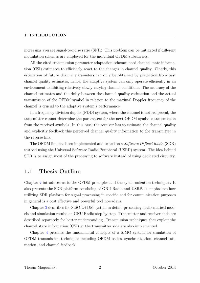
1.1 Thesis Outline
Chapter 2 introduces us to the OFDM principles and the synchronization techniques. It
also presents the SDR platform consisting of GNU Radio and USRP. It emphasizes how
utilizing SDR platform for signal processing in specific and for communication purposes
in general is a cost effective and powerful tool nowadays.
Chapter 3 describes the SISO-OFDM system in detail, presenting mathematical mod-
els and simulation results on GNU Radio step by step. Transmitter and receiver ends are
described separately for better understanding. Transmission techniques that exploit the
channel state information (CSI) at the transmitter side are also implemented.
Chapter 4 presents the fundamental concepts of a SIMO system for simulation of
OFDM transmission techniques including OFDM basics, synchronization, channel esti-
mation, and channel feedback.
Theoni Magounaki 2 October 2014
1.1 Thesis Outline
In Chapter 5 we investigate the OFDM system performance of uncoded adaptive
modulation using quadrature adaptive modulation (QAM) and phase shift keying (PSK).
The choice of the modes (4-QAM/8-PSK) to be used by the transmitter for its next
OFDM symbol is determined by the channel quality estimate of the receiver based on
the current OFDM symbol.
Finally, in Chapter 6, a conclusion is provided, followed by future work directions
that are worth considering.
Theoni Magounaki 3 October 2014

1. INTRODUCTION
Theoni Magounaki 4 October 2014
Chapter 2
Background
2.1 Software-Defined Radio (SDR)
Software-defined radio, or simply Software Radio, is a radio communication system where
components that have been typically implemented in hardware (e.g. mixers, filters, am-
plifiers, modulators/demodulators, detectors, etc.) are instead implemented by means of
software on a personal computer or embedded system. SDR attempts to offload demod-
ulation into software to allow more flexibility. Instead of only being able to tune either
AM, FM, or GPS data, SDR is theoretically able to receive any type of signal modulation.
A basic SDR system may consist of a personal computer equipped with a sound card,
or other analog-to-digital converter, preceded by some form of RF front end. Significant
amounts of signal processing are handed over to the general-purpose processor, rather
than being done in special-purpose hardware. Such a design produces a radio which can
receive and transmit widely different radio signals (sometimes referred to as waveforms)
based solely on the software used, [1].
2.2 Universal Software Radio Peripheral (USRP)
The Universal Software Radio Peripheral products are computer-hosted software radios.
The USRP product family was designed as a low-cost hardware platform for software
radio. We may say that a USRP is the bridge between the software world and the RF
world. It serves as a digital baseband and IF section of a radio communication system.
Theoni Magounaki 5 October 2014
2. BACKGROUND
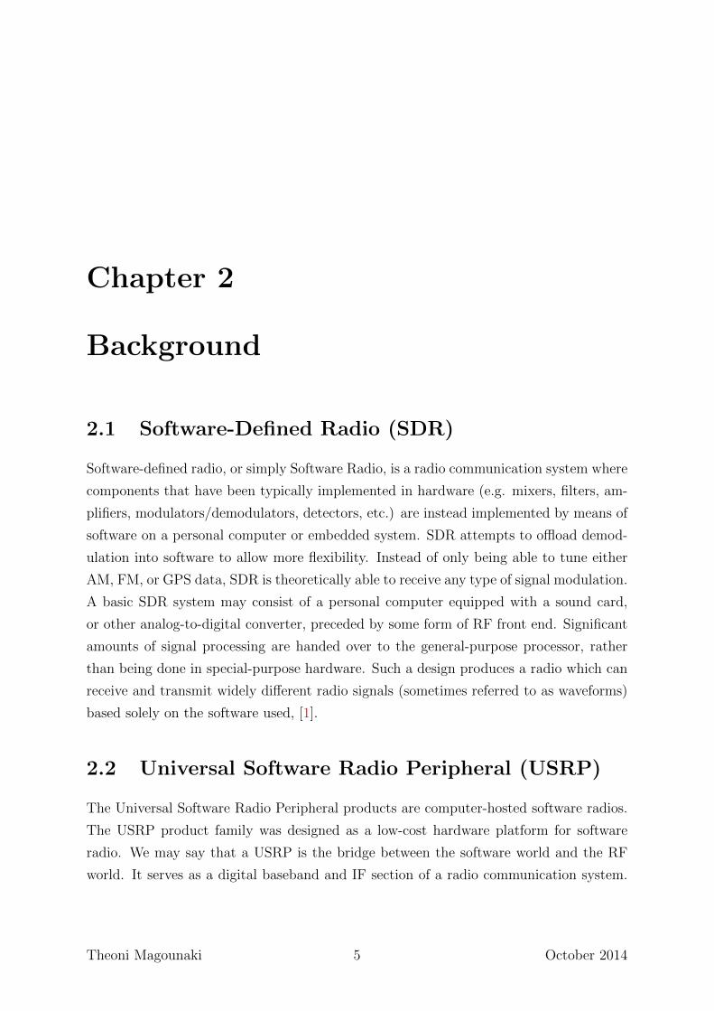
Figure 2.1: Software Defined Radio Block Diagram
All of the high speed general purpose operations like digital-up and down-conversion,
interpolation and decimation, are done on the FPGA. USRPs connect to a host computer
through a high-speed USB or Gigabit Ethernet link, which the host-based software uses
to control the USRP hardware and transmit/receive data, [2].
2.2.1 USRP1
The Ettus Research USRP1 is the original hardware of the Universal Software Radio
Peripheral family of products, which provides entry-level RF processing capability. The
architecture includes an Altera Cyclone FPGA, 64 MS/s dual ADC, 128 MS/s dual
DAC and USB 2.0 connectivity to provide data to host processors. A modular design
allows the USRP1 to operate from DC to 6 GHz. The USRP1 includes connectivity for
two daughterboards, enabling two complete transmit/receive chains. This feature makes
the USRP1 ideal for applications requiring high isolation between transmit and receive
chains, or dual-band dual transmit/receive operation. The USRP1 can stream up to 8
MS/s to and from host applications, and users can implement custom functions in the
FPGA fabric.
2.2.1.1 Motherboard and Internal Construction
The USRP1 has four high-speed analog to digital converters (ADCs), each at 12 bits
per sample, 64MSamples/sec. There are also four high-speed digital to analog converters
(DACs), each at 14 bits per sample, 128MSamples/sec. These four input and four out-
put channels are connected to an Altera Cyclone EP1C12 FPGA. The FPGA, in turn,
connects to a USB2 interface chip, the Cypress FX2, and on the computer. The USRP1
connects to the computer via a high speed USB2 interface only, and will not work with
Theoni Magounaki 6 October 2014
2.2 Universal Software Radio Peripheral (USRP)
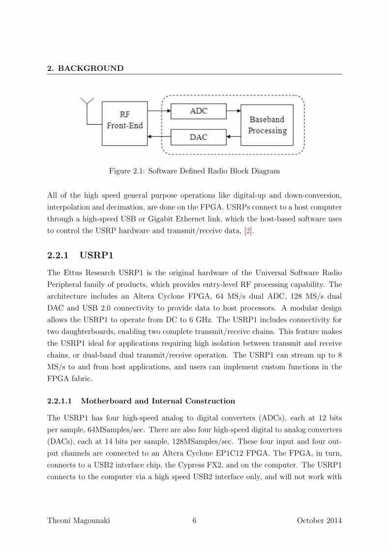
Figure 2.2: USRP 1
USB1.1. So, in principle, we have four input and four output channels if we use real sam-
pling. However, we can have more flexibility if we use complex (I and Q) sampling. Then
we have to pair them up, so we get two complex inputs and two complex outputs. The
USB controller contains the firmware that defines its behaviour and the USB endpoints.
The firmware also takes care of loading the FPGA bit stream. The FPGA handles the
high bandwidth computations and reduces the data rate to something we can send over
the USB 2.0. The Analog Device chip is a mixed signal processor that takes care of
the conversion between analog and digital signals, digital up conversion in the transmit
path and interpolation/decimation of the signals. The motherboard can have up to four
daughterboards, two for transmit and two for receive to achieve wireless communication
at different frequencies. They consist of the RF front end where the signal is upconverted
from the intermediate frequency to the carrier frequency or vice versa for the received
signal, [3].
Theoni Magounaki 7 October 2014
2. BACKGROUND
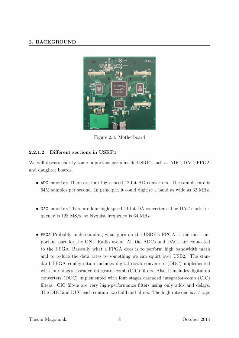
Figure 2.3: Motherboard
2.2.1.2 Different sections in USRP1
We will discuss shortly some important parts inside USRP1 such as ADC, DAC, FPGA
and daughter boards.
• ADC section There are four high speed 12-bit AD converters. The sample rate is
64M samples per second. In principle, it could digitize a band as wide as 32 MHz.
• DAC section There are four high speed 14-bit DA converters. The DAC clock fre-
quency is 128 MS/s, so Nyquist frequency is 64 MHz.
• FPGA Probably understanding what goes on the USRP’s FPGA is the most im-
portant part for the GNU Radio users. All the ADCs and DACs are connected
to the FPGA. Basically what a FPGA does is to perform high bandwidth math
and to reduce the data rates to something we can squirt over USB2. The stan-
dard FPGA configuration includes digital down converters (DDC) implemented
with four stages cascaded integrator-comb (CIC) filters. Also, it includes digital up
converters (DUC) implemented with four stages cascaded integrator-comb (CIC)
filters. CIC filters are very high-performance filters using only adds and delays.
The DDC and DUC each contain two halfband filters. The high rate one has 7 taps
Theoni Magounaki 8 October 2014
2.3 GNU Radio
and the low rate 31 taps. For spectral shaping and out of band signals rejection.
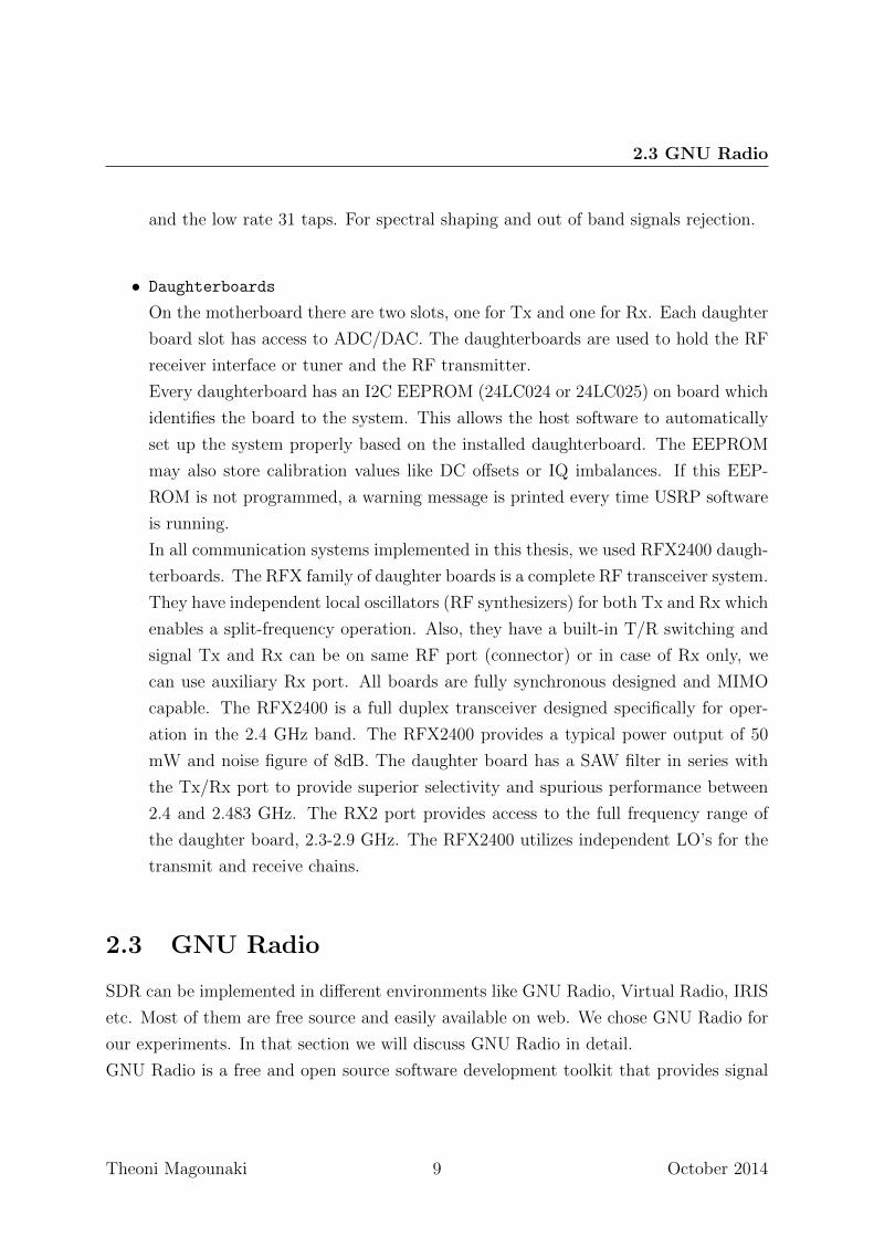
• Daughterboards
On the motherboard there are two slots, one for Tx and one for Rx. Each daughter
board slot has access to ADC/DAC. The daughterboards are used to hold the RF
receiver interface or tuner and the RF transmitter.
Every daughterboard has an I2C EEPROM (24LC024 or 24LC025) on board which
identifies the board to the system. This allows the host software to automatically
set up the system properly based on the installed daughterboard. The EEPROM
may also store calibration values like DC offsets or IQ imbalances. If this EEP-
ROM is not programmed, a warning message is printed every time USRP software
is running.
In all communication systems implemented in this thesis, we used RFX2400 daugh-
terboards. The RFX family of daughter boards is a complete RF transceiver system.
They have independent local oscillators (RF synthesizers) for both Tx and Rx which
enables a split-frequency operation. Also, they have a built-in T/R switching and
signal Tx and Rx can be on same RF port (connector) or in case of Rx only, we
can use auxiliary Rx port. All boards are fully synchronous designed and MIMO
capable. The RFX2400 is a full duplex transceiver designed specifically for oper-
ation in the 2.4 GHz band. The RFX2400 provides a typical power output of 50
mW and noise figure of 8dB. The daughter board has a SAW filter in series with
the Tx/Rx port to provide superior selectivity and spurious performance between
2.4 and 2.483 GHz. The RX2 port provides access to the full frequency range of
the daughter board, 2.3-2.9 GHz. The RFX2400 utilizes independent LO’s for the
transmit and receive chains.
2.3 GNU Radio
SDR can be implemented in different environments like GNU Radio, Virtual Radio, IRIS
etc. Most of them are free source and easily available on web. We chose GNU Radio for
our experiments. In that section we will discuss GNU Radio in detail.
GNU Radio is a free and open source software development toolkit that provides signal
Theoni Magounaki 9 October 2014
2. BACKGROUND
Figure 2.4: Daughterboard
processing blocks to implement software-defined radio systems. GNU Radio is primar-
ily developed using the GNU/Linux operating system, but, Max OS and Windows are
also supported. In GNU Radio, a radio system is represented as a directed signal flow
graph where graph vertices are known as signal processing blocks and edges indicate a
connection between the two blocks. Data flows in one direction from a signal source
to one or more signal sinks. This construction of software radio is similar to develop-
ment of hardware radios, but with an additional restriction that the signal flow in a flow
graph cannot form a feedback cycle, so implementation of any feedback mechanisms must
be contained within one signal processing block. In GNU Radio, the signal processing
blocks are defined in C++ for performance, while the connections between the blocks for
Theoni Magounaki 10 October 2014
2.4 Introduction to OFDM
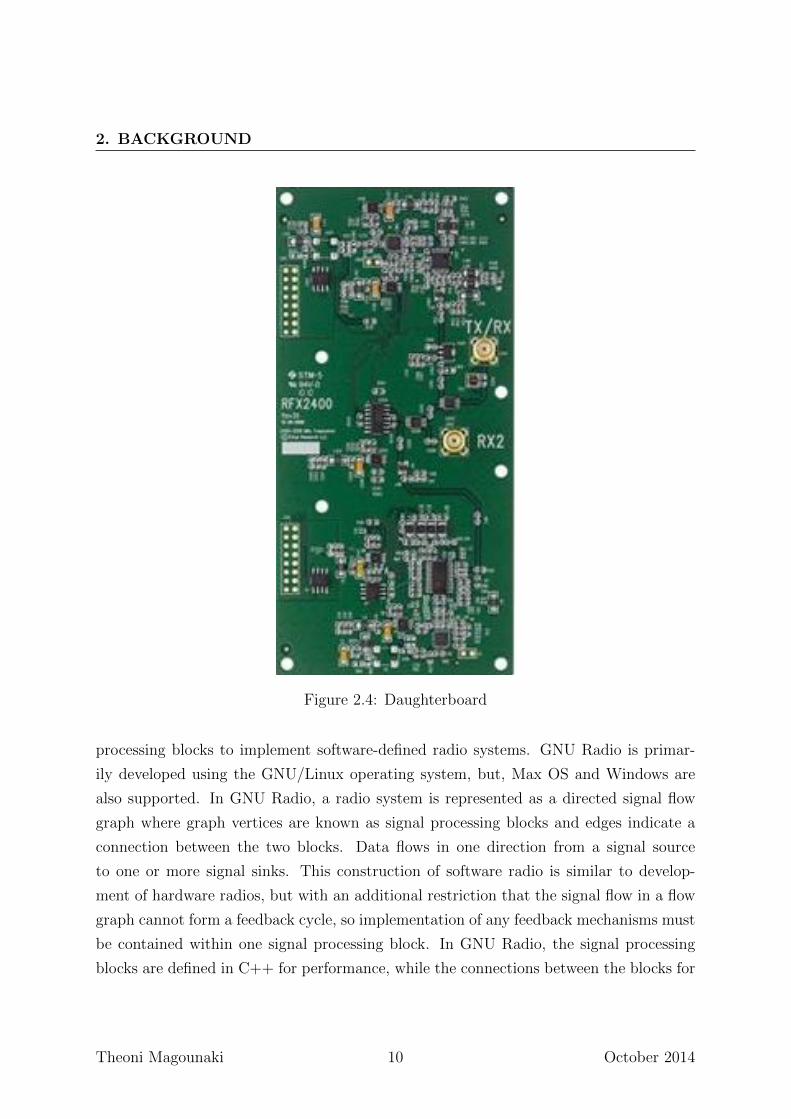
Figure 2.5: GNU Radio Architecture
a given application are declared in Python. Using a high level language like Python allows
users to quickly create different applications by constructing a signal flow graph simply
by making connections between smaller building blocks. This approach meant that the
agility of software development in a high level language can be maximized while at the
same time sidestepping its drawback of slow performance by acting only as ’glue’ code
and offloading the heavy lifting to C++ compiled code. GNU Radio uses a number of
data types to represent the signal at the interfaces of each of the signal processing blocks.
The data type used by a particular block can usually be identified through the naming
convention that each block should be suffixed with a code to represent its interface.
The architecture of GNU Radio is displayed in Figure 2.5.
There are many advantages associated with the use of GNU Radio and are given
below:
• Hybrid System consisting of C++/Python.
• Can be reconfigurable at run time.
• Intelligent run time scheduler to indicate completion of work.
• Graphical User Interface (GUI) to view Time Scope and FFT.
• More than 100 Signal Processing Blocks including Filters, Modulators and Error
Correcting Codes.
2.4 Introduction to OFDM
Digital bandpass modulation techniques can be broadly classified into two categories,
single-carrier and multicarrier. In a single-carrier modulation, data is transmitted by
using a single radio frequency (RF) carrier. To overcome the frequency selectivity of the
Theoni Magounaki 11 October 2014
2. BACKGROUND
wideband channel experienced by single-carrier transmission, we must use some kind of
channel equalization.
OFDM is a multi-carrier modulation technique where data symbols modulate a par-
allel collection of regularly spaced sub-carriers, [4, 5]. Each sub-carrier is modulated with
a conventional modulation scheme, such as quadrature amplitude modulation (QAM)
or phase shift keying (PSK), at a low symbol rate, maintaining total data rates simi-
lar to conventional single-carrier modulation schemes with the same bandwidth. The
sub-carriers have the minimum frequency separation required to maintain orthogonality
of their corresponding time domain waveforms, yet the signal spectra corresponding to
the different sub-carriers overlap in frequency. The spectral overlap results in a wave-
form that uses the available bandwidth with a very high bandwidth efficiency. The
primary advantage of OFDM over single-carrier schemes is its ability to cope with se-
vere channel conditions, for example, attenuation of high frequencies in a long copper
wire, narrowband interference and frequency-selective fading due to multipath, without
complex equalization filters. Channel equalization is simplified because OFDM may be
viewed as many slowly modulated narrowband signals rather than one rapidly modulated
wideband signal. The low symbol rate makes the use of a guard interval between sym-
bols affordable, making it possible to eliminate intersymbol interference (ISI) and utilize
echoes and time-spreading to achieve diversity gain.
2.5 Analog OFDM System Model
An OFDM carrier signal is the sum of a number of orthogonal subcarriers, with baseband
data on each subcarrier being modulated using quadrature amplitude modulation (QAM)
or phase-shift keying (PSK). In an OFDM signal, the carriers are arranged in such a way
that the sidebands of the individual carriers overlap but the signal can still be received
without adjacent carrier interference. In order to do this, the carriers must be orthogonal.
The OFDM signal in the time domain is [6]
s(t) =N−1∑k=0
skej2πfkt, 0 ≤ t ≤ Ts
where:
sk : the k-th complex symbol to be transmitted
Theoni Magounaki 12 October 2014
2.5 Analog OFDM System Model
N : the number of symbols
∆f : subcarrier space of OFDM
Ts : symbol duration of OFDM
fk = f0 + k∆f : the frequency of the k-th subcarrier
In order for the receiver to demodulate the OFDM signal, the symbol duration must be
long enough such that Ts∆f = 1, which is also called orthogonality condition. Because
of the orthogonality condition, we have
1
Ts
Ts∫0
(ej2πfkt)(ej2πflt)∗dt
=1
Ts
∫ Ts
0
ej2π(fk−fl)tdt
=1
Ts
∫ Ts
0
ej2π(k−l)∆ftdt
= δ[k − l]
(2.1)
where δ[k − l] is the delta function defined as
δ[n] =
{1, n = 0,
0, otherwise.
Equation (2.1) shows that{ej2πfkt
}N−1
k=0is a set of orthogonal functions. Using this
property and assuming ideal channel, the OFDM signal can be demodulated by
1
Ts
∫ Ts
0
s(t)e−j2πfktdt
=1
Ts
∫ Ts
0
N−1∑l=0
sl(ej2πflt)(ej2πfkt)∗dt
=N−1∑l=0
slδ[l − k]
= sk.
(2.2)
Theoni Magounaki 13 October 2014
2. BACKGROUND
2.6 Digital OFDM System Model
In this section, we assume ideal timing and frequency synchronization. Consider a wide-
band wireless channel, with a discrete-time impulse response given by hl, l = 0, . . . , L−1.
We assume that the channel remains constant over the time period of interest, [7]. Let
the data block of length N be
d = [d0, . . . , dN−1]T .
Taking the inverse Discrete Fourier Transform (IDFT) of d, the data block is expressed
as
d = IDFT (d) = [d0, . . . , dN−1]T .
Using d, we construct the vector s, by inserting a cyclic prefix, of length L,
s =
dN−L+1...
dN−1
d0...
dN−1
=
s1...
...sN+L−1
.
Using s as input to the channel, the output is written as follows
ym =L−1∑l=0
hlsm−l + wm, m = 1, . . . , N + L− 1.
At the receiver we ignore the first L − 1 output symbols. Using the N output symbols
ym, m = L, . . . , N + L− 1, we construct the vector y′
y′=
y′0...
y′N−1
=
yL...
yN+L−1
.It can be shown that
y′= d⊗N h + w,
where w = [wL, . . . , wN+L−1]T and d ⊗N h is the circular convolution, of length N , of
vectors d and h. To prove the above assertion, consider
y′
0 = yL =L−1∑l=0
hlsL−l = h0d0 +L−1∑l=1
hldN−l.
Theoni Magounaki 14 October 2014
2.7 Detailed Digital OFDM System Model
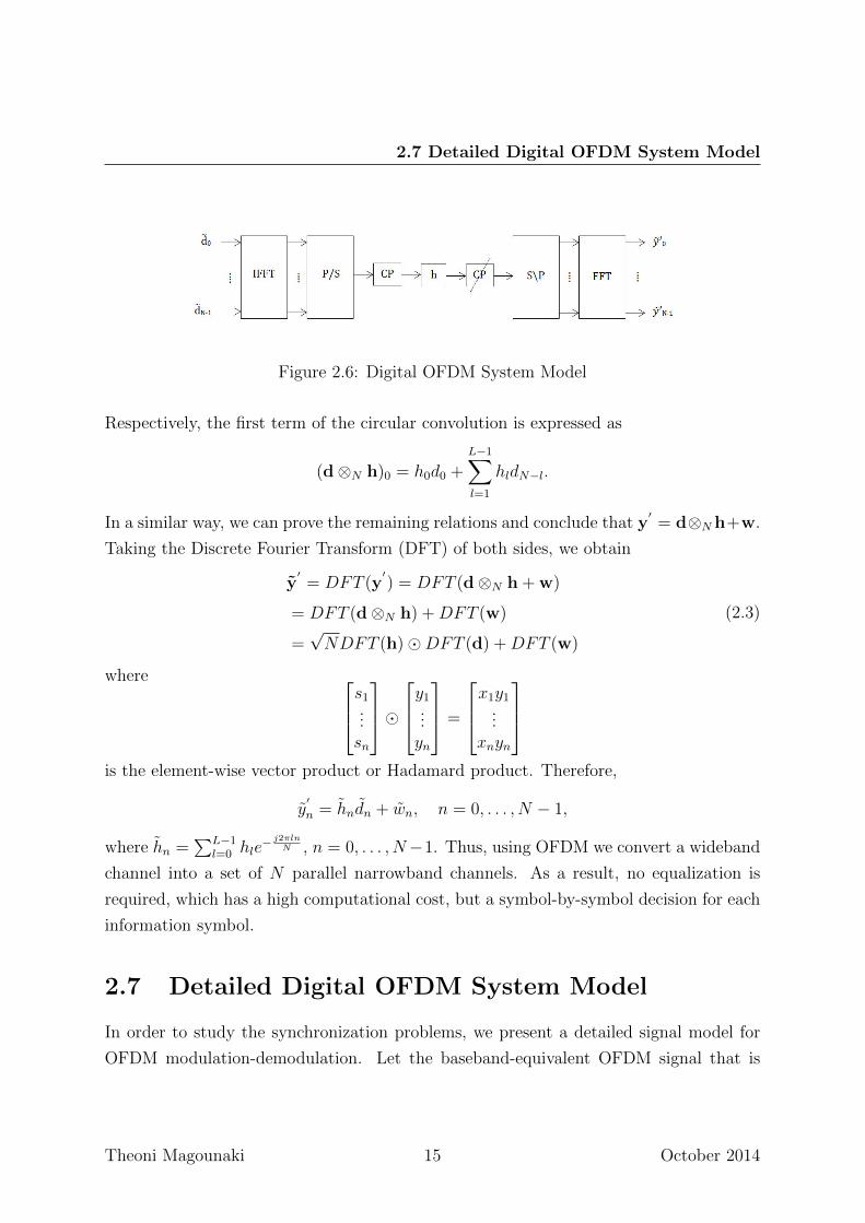
Figure 2.6: Digital OFDM System Model
Respectively, the first term of the circular convolution is expressed as
(d⊗N h)0 = h0d0 +L−1∑l=1
hldN−l.
In a similar way, we can prove the remaining relations and conclude that y′= d⊗Nh+w.
Taking the Discrete Fourier Transform (DFT) of both sides, we obtain
y′= DFT (y
′) = DFT (d⊗N h + w)
= DFT (d⊗N h) +DFT (w)
=√NDFT (h)�DFT (d) +DFT (w)
(2.3)
where s1...sn
�y1
...yn
=
x1y1...
xnyn
is the element-wise vector product or Hadamard product. Therefore,
y′
n = hndn + wn, n = 0, . . . , N − 1,
where hn =∑L−1
l=0 hle− j2πln
N , n = 0, . . . , N−1. Thus, using OFDM we convert a wideband
channel into a set of N parallel narrowband channels. As a result, no equalization is
required, which has a high computational cost, but a symbol-by-symbol decision for each
information symbol.
2.7 Detailed Digital OFDM System Model
In order to study the synchronization problems, we present a detailed signal model for
OFDM modulation-demodulation. Let the baseband-equivalent OFDM signal that is
Theoni Magounaki 15 October 2014
2. BACKGROUND
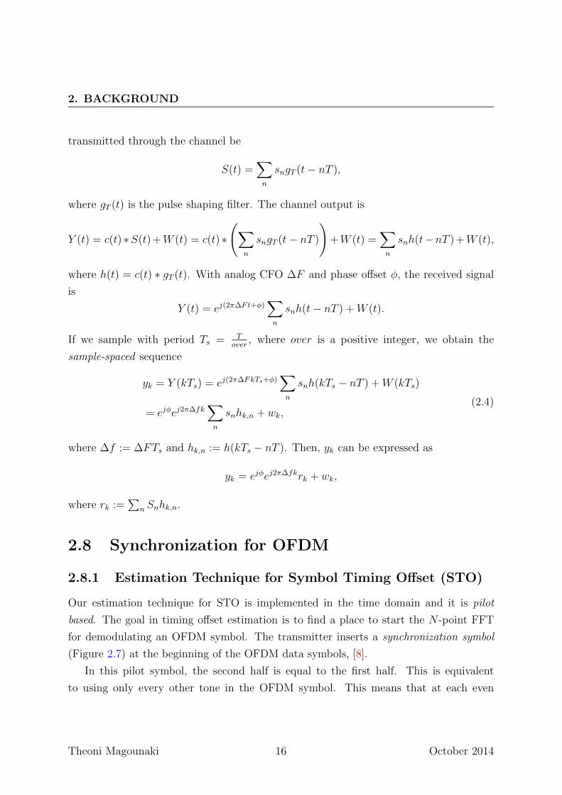
transmitted through the channel be
S(t) =∑n
sngT (t− nT ),
where gT (t) is the pulse shaping filter. The channel output is
Y (t) = c(t) ∗S(t) +W (t) = c(t) ∗
(∑n
sngT (t− nT )
)+W (t) =
∑n
snh(t−nT ) +W (t),
where h(t) = c(t) ∗ gT (t). With analog CFO ∆F and phase offset φ, the received signal
is
Y (t) = ej(2π∆Ft+φ)∑n
snh(t− nT ) +W (t).
If we sample with period Ts = Tover
, where over is a positive integer, we obtain the
sample-spaced sequence
yk = Y (kTs) = ej(2π∆FkTs+φ)∑n
snh(kTs − nT ) +W (kTs)
= ejφej2π∆fk∑n
snhk,n + wk,(2.4)
where ∆f := ∆FTs and hk,n := h(kTs − nT ). Then, yk can be expressed as
yk = ejφej2π∆fkrk + wk,
where rk :=∑
n Snhk,n.
2.8 Synchronization for OFDM
2.8.1 Estimation Technique for Symbol Timing Offset (STO)
Our estimation technique for STO is implemented in the time domain and it is pilot
based. The goal in timing offset estimation is to find a place to start the N -point FFT
for demodulating an OFDM symbol. The transmitter inserts a synchronization symbol
(Figure 2.7) at the beginning of the OFDM data symbols, [8].
In this pilot symbol, the second half is equal to the first half. This is equivalent
to using only every other tone in the OFDM symbol. This means that at each even
Theoni Magounaki 16 October 2014
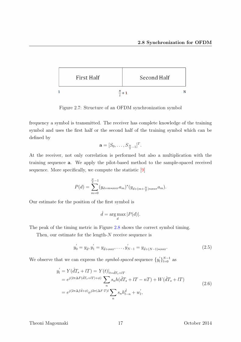
2.8 Synchronization for OFDM
Figure 2.7: Structure of an OFDM synchronization symbol
frequency a symbol is transmitted. The receiver has complete knowledge of the training
symbol and uses the first half or the second half of the training symbol which can be
defined by
a = [S0, . . . , SN2−1]T .
At the receiver, not only correlation is performed but also a multiplication with the
training sequence a. We apply the pilot-based method to the sample-spaced received
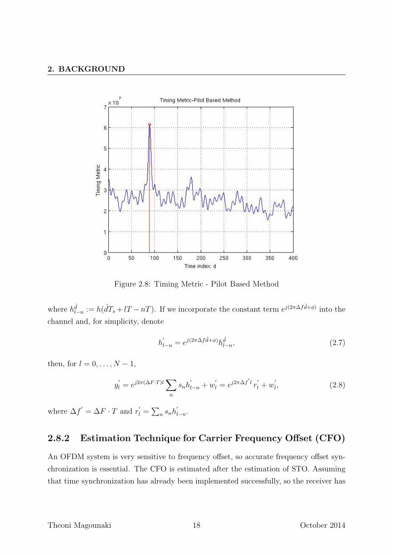
sequence. More specifically, we compute the statistic [9]
P (d) =
N2−1∑
m=0
(yd+m∗overam)∗(yd+(m+N2
)∗overam).
Our estimate for the position of the first symbol is
d = arg maxd
|P (d)|.
The peak of the timing metric in Figure 2.8 shows the correct symbol timing.
Then, our estimate for the length-N receive sequence is
y′
0 = yd, y′
1 = yd+over, . . . , y′
N−1 = yd+(N−1)∗over. (2.5)
We observe that we can express the symbol-spaced sequence {y′
l}N−1l=0 as
y′
l = Y (dTs + lT ) = Y (t)|t=dTs+lT= ej(2π∆F (dTs+lT )+φ)
∑n
snh(dTs + lT − nT ) +W (dTs + lT )
= ej(2π∆fd+φ)ej2π(∆F ·T )l∑n
snhdl−n + w
′
l ,
(2.6)
Theoni Magounaki 17 October 2014
2. BACKGROUND
Figure 2.8: Timing Metric - Pilot Based Method
where hdl−n := h(dTs + lT −nT ). If we incorporate the constant term ej(2π∆fd+φ) into the
channel and, for simplicity, denote
h′
l−n = ej(2π∆fd+φ)hdl−n, (2.7)
then, for l = 0, . . . , N − 1,
y′
l = ej2π(∆F ·T )l∑n
snh′
l−n + w′
l = ej2π∆f′l r
′
l + w′
l , (2.8)
where ∆f′= ∆F · T and r
′
l =∑
n snh′
l−n.
2.8.2 Estimation Technique for Carrier Frequency Offset (CFO)
An OFDM system is very sensitive to frequency offset, so accurate frequency offset syn-
chronization is essential. The CFO is estimated after the estimation of STO. Assuming
that time synchronization has already been implemented successfully, so the receiver has
Theoni Magounaki 18 October 2014
2.9 Channel Estimation
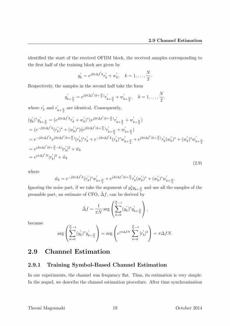
identified the start of the received OFDM block, the received samples corresponding to
the first half of the training block are given by
y′
k = ej2π∆f′kr
′
k + w′
k, k = 1, . . . ,N
2.
Respectively, the samples in the second half take the form
y′
k+N2
= ej2π∆f′(k+N
2)r
′
k+N2
+ w′
k+N2, k = 1, . . . ,
N
2,
where r′
k and r′
k+N2
are identical. Consequently,
(y′
k)∗y
′
k+N2
= (ej2π∆f′kr
′
k + w′
k)∗(ej2π∆f
′(k+N
2)r
′
k+N2
+ w′
k+N2
)
= (e−j2π∆f′k(r
′
k)∗ + (w
′
k)∗)(ej2π∆f
′(k+N
2)r
′
k+N2
+ w′
k+N2
)
= e−j2π∆f′kej2π∆f
′(k+N
2)(r
′
k)∗r
′
k + e−j2π∆f′k(r
′
k)∗w
′
k+N2
+ ej2π∆f′(k+N
2)r
′
k(w′
k)∗ + (w
′
k)∗w
′
k+N2
= ej2π∆f′(k+N
2−k)|r′k|2 + wk
= ejπ∆f′N |r′k|2 + wk
(2.9)
where
wk = e−j2π∆f′k(r
′
k)∗w
′
k+N2
+ ej2π∆f′(k+N
2 r′
k(w′
k)∗ + (w
′
k)∗w
′
k+N2.
Ignoring the noise part, if we take the argument of y∗kyk+N2
and use all the samples of the
preamble part, an estimate of CFO, ∆f , can be derived by
∆f =1
πNarg
N2−1∑
k=0
(y′
k)∗y
′
k+N2
,
because
arg
N2−1∑
k=0
(y′
k)∗y
′
k+N2
= arg
ejπ∆fN
N2−1∑
k=0
|r′k|2 = π∆fN.
2.9 Channel Estimation
2.9.1 Training Symbol-Based Channel Estimation
In our experiments, the channel was frequency flat. Thus, its estimation is very simple.
In the sequel, we describe the channel estimation procedure. After time synchronization
Theoni Magounaki 19 October 2014
2. BACKGROUND
and CFO correction, the received block can be expressed as
y′
k = skh+ wk, k = 0, . . . , N − 1, (2.10)
or in vector form
y′= sh+ w. (2.11)
Assuming that s is known (i.e., s is a pilot block), the LS channel estimate is given by
hLS =(sHs)−1
sHy′, (2.12)
where ·H denotes Hermitian transpose.
Theoni Magounaki 20 October 2014
Chapter 3
Single Input Single Output System
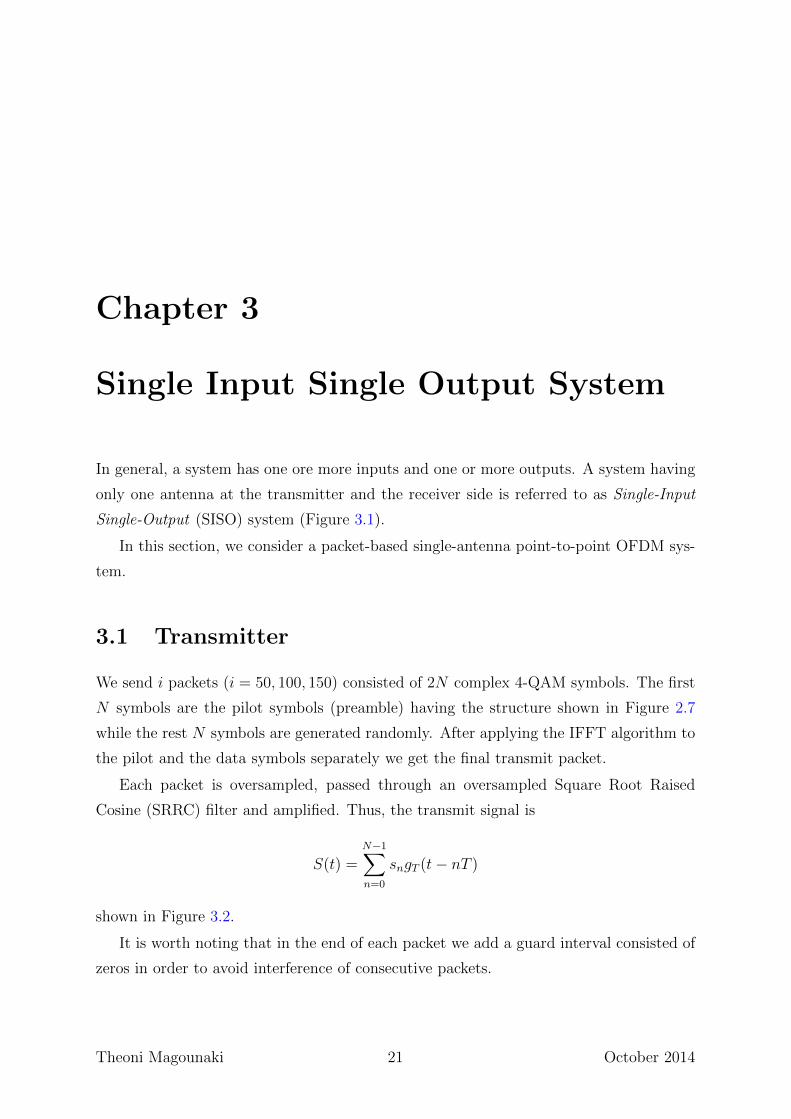
In general, a system has one ore more inputs and one or more outputs. A system having
only one antenna at the transmitter and the receiver side is referred to as Single-Input
Single-Output (SISO) system (Figure 3.1).
In this section, we consider a packet-based single-antenna point-to-point OFDM sys-
tem.
3.1 Transmitter
We send i packets (i = 50, 100, 150) consisted of 2N complex 4-QAM symbols. The first
N symbols are the pilot symbols (preamble) having the structure shown in Figure 2.7
while the rest N symbols are generated randomly. After applying the IFFT algorithm to
the pilot and the data symbols separately we get the final transmit packet.
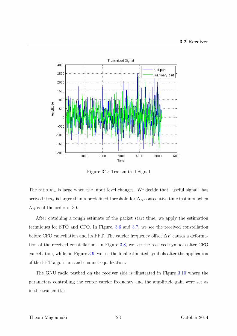
Each packet is oversampled, passed through an oversampled Square Root Raised
Cosine (SRRC) filter and amplified. Thus, the transmit signal is
S(t) =N−1∑n=0
sngT (t− nT )
shown in Figure 3.2.
It is worth noting that in the end of each packet we add a guard interval consisted of
zeros in order to avoid interference of consecutive packets.
Theoni Magounaki 21 October 2014
3. SINGLE INPUT SINGLE OUTPUT SYSTEM
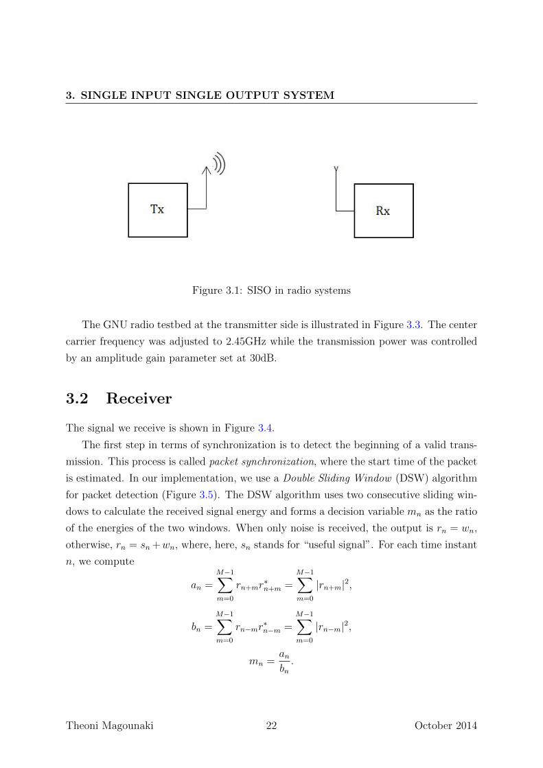
Figure 3.1: SISO in radio systems
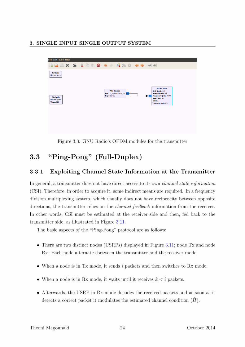
The GNU radio testbed at the transmitter side is illustrated in Figure 3.3. The center
carrier frequency was adjusted to 2.45GHz while the transmission power was controlled
by an amplitude gain parameter set at 30dB.
3.2 Receiver
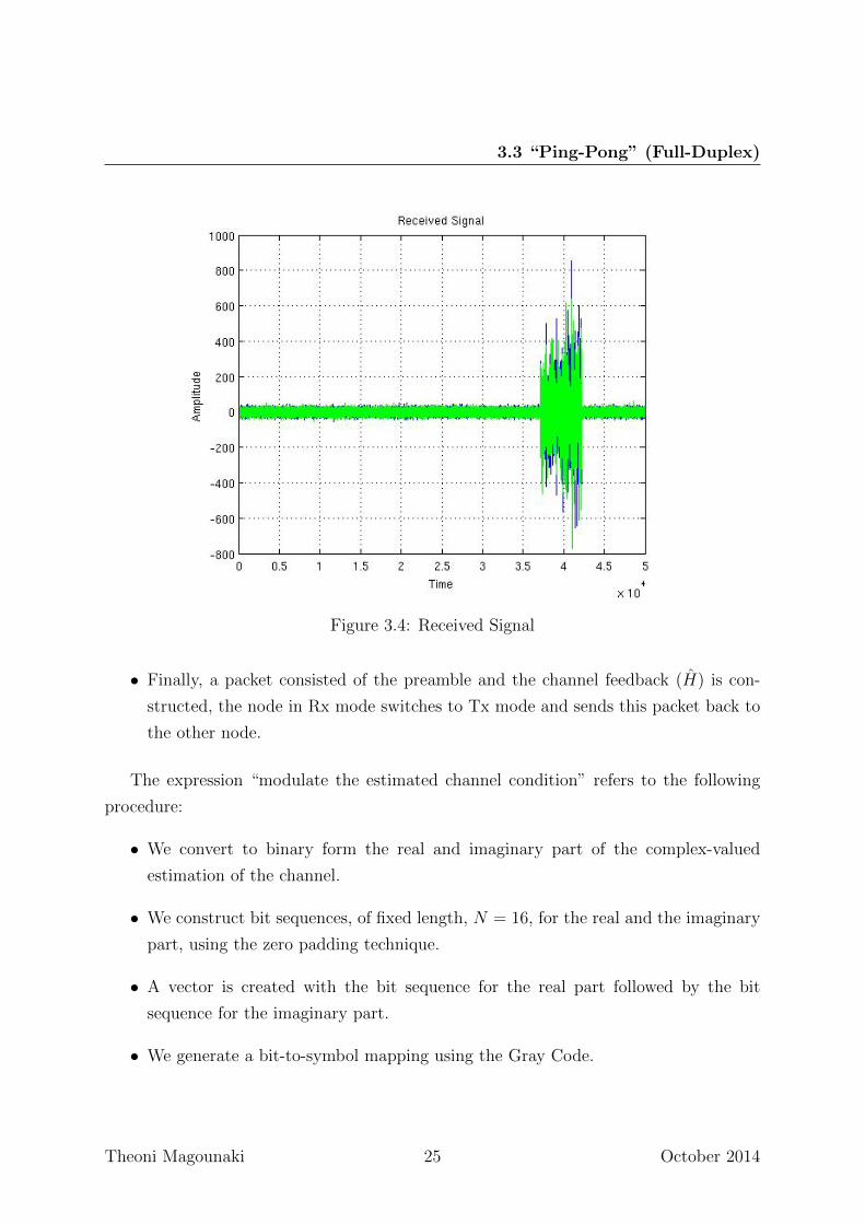
The signal we receive is shown in Figure 3.4.
The first step in terms of synchronization is to detect the beginning of a valid trans-
mission. This process is called packet synchronization, where the start time of the packet
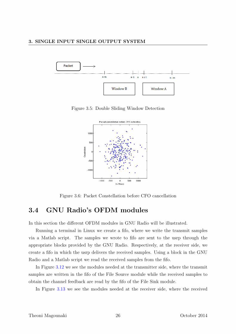
is estimated. In our implementation, we use a Double Sliding Window (DSW) algorithm
for packet detection (Figure 3.5). The DSW algorithm uses two consecutive sliding win-
dows to calculate the received signal energy and forms a decision variable mn as the ratio
of the energies of the two windows. When only noise is received, the output is rn = wn,
otherwise, rn = sn +wn, where, here, sn stands for “useful signal”. For each time instant
n, we compute
an =M−1∑m=0
rn+mr∗n+m =
M−1∑m=0
|rn+m|2,
bn =M−1∑m=0
rn−mr∗n−m =
M−1∑m=0
|rn−m|2,
mn =anbn.
Theoni Magounaki 22 October 2014
3.2 Receiver
Figure 3.2: Transmitted Signal
The ratio mn is large when the input level changes. We decide that “useful signal” has
arrived if mn is larger than a predefined threshold for NA consecutive time instants, when
NA is of the order of 30.
After obtaining a rough estimate of the packet start time, we apply the estimation
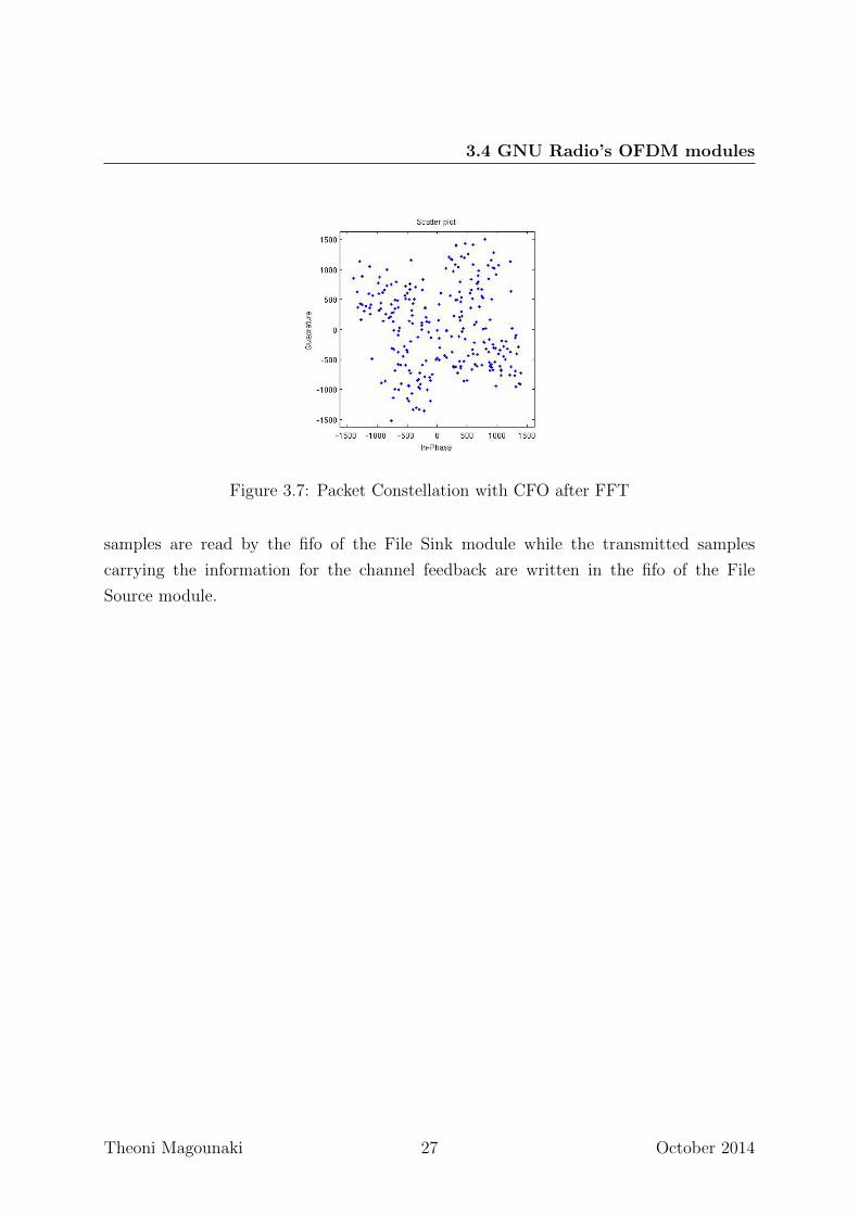
techniques for STO and CFO. In Figure, 3.6 and 3.7, we see the received constellation
before CFO cancellation and its FFT. The carrier frequency offset ∆F causes a deforma-
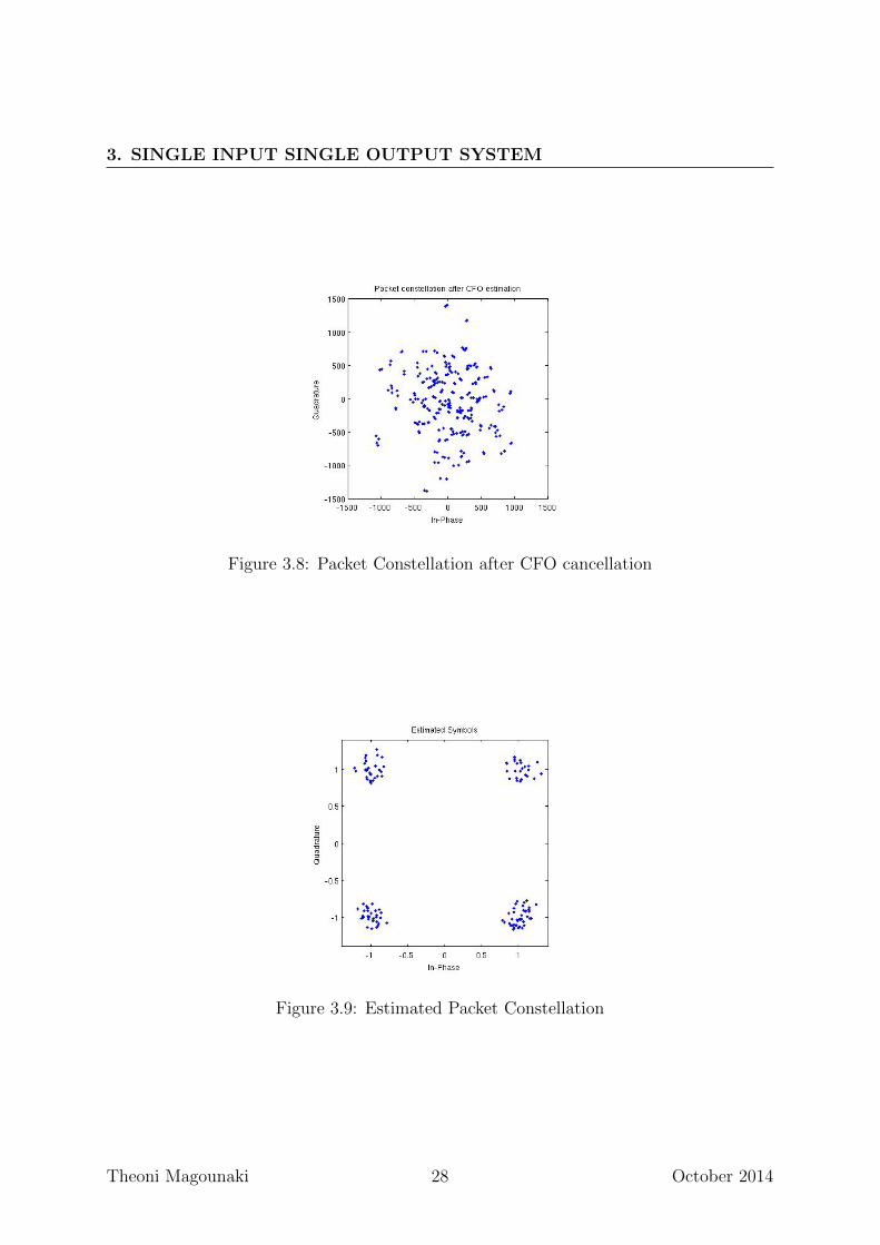
tion of the received constellation. In Figure 3.8, we see the received symbols after CFO
cancellation, while, in Figure 3.9, we see the final estimated symbols after the application
of the FFT algorithm and channel equalization.
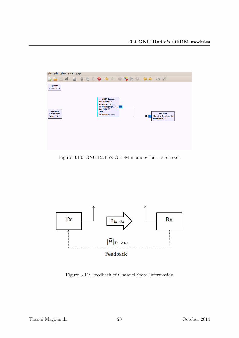
The GNU radio testbed on the receiver side is illustrated in Figure 3.10 where the
parameters controlling the center carrier frequency and the amplitude gain were set as
in the transmitter.
Theoni Magounaki 23 October 2014
3. SINGLE INPUT SINGLE OUTPUT SYSTEM
Figure 3.3: GNU Radio’s OFDM modules for the transmitter
3.3 “Ping-Pong” (Full-Duplex)
3.3.1 Exploiting Channel State Information at the Transmitter
In general, a transmitter does not have direct access to its own channel state information
(CSI). Therefore, in order to acquire it, some indirect means are required. In a frequency
division multiplexing system, which usually does not have reciprocity between opposite
directions, the transmitter relies on the channel feedback information from the receiver.
In other words, CSI must be estimated at the receiver side and then, fed back to the
transmitter side, as illustrated in Figure 3.11.
The basic aspects of the “Ping-Pong” protocol are as follows:
• There are two distinct nodes (USRPs) displayed in Figure 3.11; node Tx and node
Rx. Each node alternates between the transmitter and the receiver mode.
• When a node is in Tx mode, it sends i packets and then switches to Rx mode.
• When a node is in Rx mode, it waits until it receives k < i packets.
• Afterwards, the USRP in Rx mode decodes the received packets and as soon as it
detects a correct packet it modulates the estimated channel condition (H).
Theoni Magounaki 24 October 2014
3.3 “Ping-Pong” (Full-Duplex)
Figure 3.4: Received Signal
• Finally, a packet consisted of the preamble and the channel feedback (H) is con-
structed, the node in Rx mode switches to Tx mode and sends this packet back to
the other node.
The expression “modulate the estimated channel condition” refers to the following
procedure:
• We convert to binary form the real and imaginary part of the complex-valued
estimation of the channel.
• We construct bit sequences, of fixed length, N = 16, for the real and the imaginary
part, using the zero padding technique.
• A vector is created with the bit sequence for the real part followed by the bit
sequence for the imaginary part.
• We generate a bit-to-symbol mapping using the Gray Code.
Theoni Magounaki 25 October 2014
3. SINGLE INPUT SINGLE OUTPUT SYSTEM
Figure 3.5: Double Sliding Window Detection
Figure 3.6: Packet Constellation before CFO cancellation
3.4 GNU Radio’s OFDM modules
In this section the different OFDM modules in GNU Radio will be illustrated.
Running a terminal in Linux we create a fifo, where we write the transmit samples
via a Matlab script. The samples we wrote to fifo are sent to the usrp through the
appropriate blocks provided by the GNU Radio. Respectively, at the receiver side, we
create a fifo in which the usrp delivers the received samples. Using a block in the GNU
Radio and a Matlab script we read the received samples from the fifo.
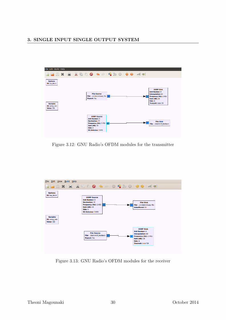
In Figure 3.12 we see the modules needed at the transmitter side, where the transmit
samples are written in the fifo of the File Source module while the received samples to
obtain the channel feedback are read by the fifo of the File Sink module.
In Figure 3.13 we see the modules needed at the receiver side, where the received
Theoni Magounaki 26 October 2014
3.4 GNU Radio’s OFDM modules
Figure 3.7: Packet Constellation with CFO after FFT
samples are read by the fifo of the File Sink module while the transmitted samples
carrying the information for the channel feedback are written in the fifo of the File
Source module.
Theoni Magounaki 27 October 2014
3. SINGLE INPUT SINGLE OUTPUT SYSTEM
Figure 3.8: Packet Constellation after CFO cancellation
Figure 3.9: Estimated Packet Constellation
Theoni Magounaki 28 October 2014
3.4 GNU Radio’s OFDM modules
Figure 3.10: GNU Radio’s OFDM modules for the receiver
Figure 3.11: Feedback of Channel State Information
Theoni Magounaki 29 October 2014
3. SINGLE INPUT SINGLE OUTPUT SYSTEM
Figure 3.12: GNU Radio’s OFDM modules for the transmitter
Figure 3.13: GNU Radio’s OFDM modules for the receiver
Theoni Magounaki 30 October 2014
Chapter 4
Single Input Multiple Output
System
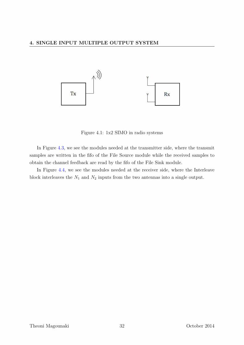
A system having only one transmit antenna and multiple antennas at the receiver side is
known as Single Input Multiple Output (SIMO) system (Figure 4.1).
4.1 System Model
We assume that the pilot symbols are known to the receiver. The transmitter sends a
sequence x. Assuming perfect symbol timing and carrier frequency synchronization, the
sequence received by the receiver can be expressed as
y =
[y1
y2
]=
[h1
h2
]x+
[w1
w2
]= hx+ w
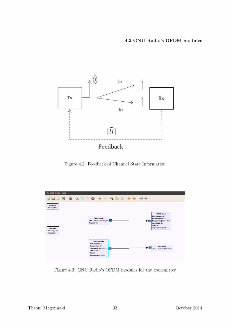
We estimate each of the channels h1 and h2 using the same channel estimation tech-
nique as in the SISO system. The packet which is finally fed back to the initial transmitter
consists of the preamble followed by the modulated estimates of the channel state, h1, h2
(Figure 4.2).
4.2 GNU Radio’s OFDM modules
In this section the different OFDM modules in GNU Radio will be illustrated.
Theoni Magounaki 31 October 2014
4. SINGLE INPUT MULTIPLE OUTPUT SYSTEM
Figure 4.1: 1x2 SIMO in radio systems
In Figure 4.3, we see the modules needed at the transmitter side, where the transmit
samples are written in the fifo of the File Source module while the received samples to
obtain the channel feedback are read by the fifo of the File Sink module.
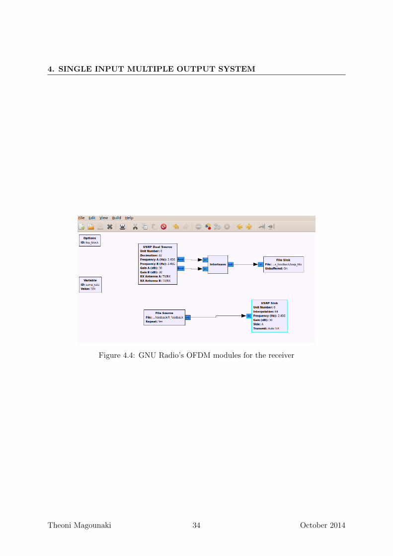
In Figure 4.4, we see the modules needed at the receiver side, where the Interleave
block interleaves the N1 and N2 inputs from the two antennas into a single output.
Theoni Magounaki 32 October 2014
4.2 GNU Radio’s OFDM modules
Figure 4.2: Feedback of Channel State Information
Figure 4.3: GNU Radio’s OFDM modules for the transmitter
Theoni Magounaki 33 October 2014
4. SINGLE INPUT MULTIPLE OUTPUT SYSTEM
Figure 4.4: GNU Radio’s OFDM modules for the receiver
Theoni Magounaki 34 October 2014
Chapter 5
Single Transmitter Multiple
Receivers System
We implemented a system having a single antenna at the transmit USRP and at the
receiver side we used two USRPs having a single antenna on each (Figure 5.1), [10, 11].
5.1 Adaptive Orthogonal Frequency Division Multi-
ple Access
The two receivers use the received OFDM symbol to gain information concerning the
frequency domain channel transfer function, and employ this information to determine
the modulation parameters to be used for the next reverse link packet. The only variable
parameter of our system is the choice of the modulation scheme out of a set of Quadrature
Amplitude Modulation (QAM) and Phase Shift Keying (PSK).
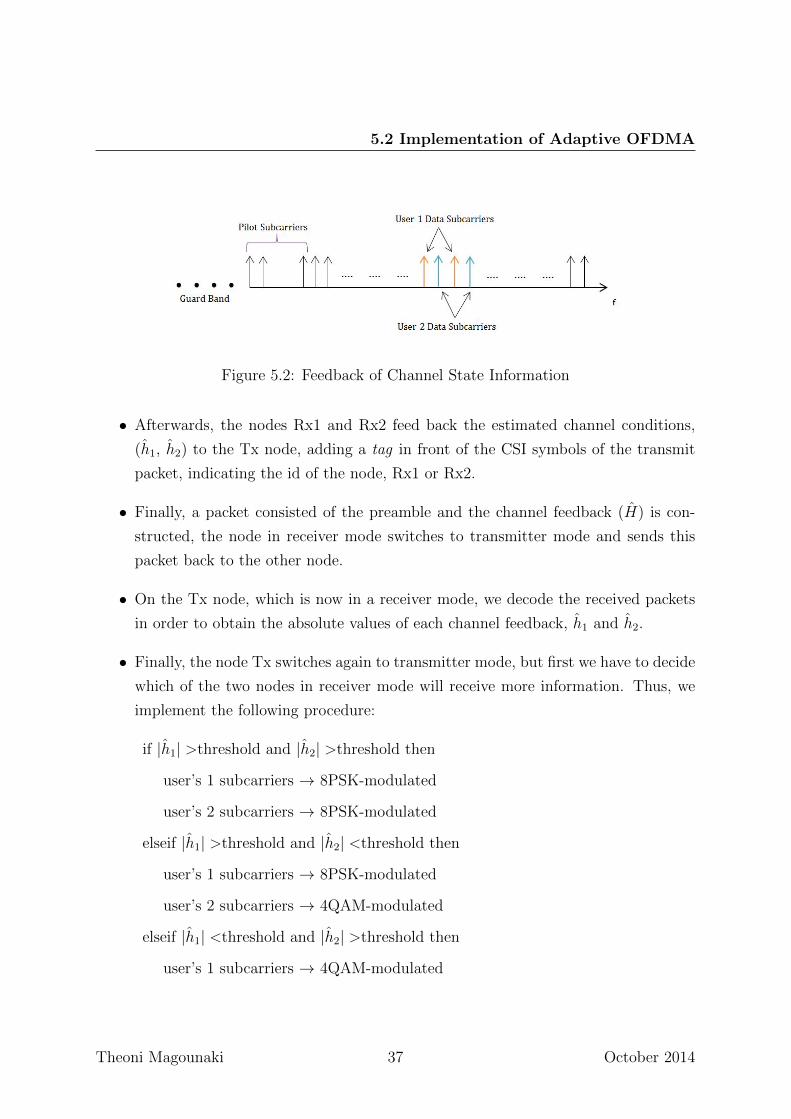
In order to keep the system complexity low, the modulation scheme is not varied on a
subcarrier-by-subcarrier basis, but instead the total OFDM bandwidth of N subcarriers
is split into blocks of subcarriers, and the same modulation scheme is employed for all
subcarriers of the same group. A subset of subcarriers defined as subchannel is allocated
to each user. We perform the subcarrier grouping shown in Figure 5.2.
The choice of the modulation scheme for each group is determined by estimating the
channel h (channel feedback) on the basis of the received OFDM symbol and comparing
it with a threshold. The receiver has not a priori knowledge of the modulation scheme
Theoni Magounaki 35 October 2014
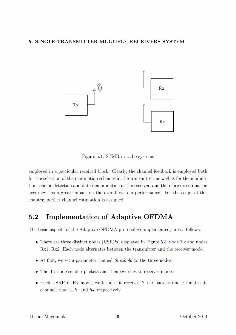
5. SINGLE TRANSMITTER MULTIPLE RECEIVERS SYSTEM
Figure 5.1: STMR in radio systems
employed in a particular received block. Clearly, the channel feedback is employed both
for the selection of the modulation schemes at the transmitter, as well as for the modula-
tion scheme detection and data demodulation at the receiver, and therefore its estimation
accuracy has a great impact on the overall system performance. For the scope of this
chapter, perfect channel estimation is assumed.
5.2 Implementation of Adaptive OFDMA
The basic aspects of the Adaptive OFDMA protocol we implemented, are as follows:
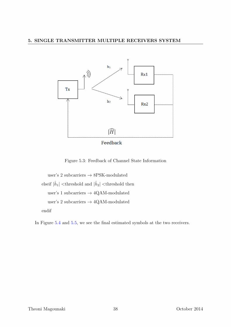
• There are three distinct nodes (USRPs) displayed in Figure 5.3; node Tx and nodes
Rx1, Rx2. Each node alternates between the transmitter and the receiver mode.
• At first, we set a parameter, named threshold to the three nodes.
• The Tx node sends i packets and then switches to receiver mode.
• Each USRP in Rx mode, waits until it receives k < i packets and estimates its
channel, that is, h1 and h2, respectively.
Theoni Magounaki 36 October 2014
5.2 Implementation of Adaptive OFDMA
Figure 5.2: Feedback of Channel State Information
• Afterwards, the nodes Rx1 and Rx2 feed back the estimated channel conditions,
(h1, h2) to the Tx node, adding a tag in front of the CSI symbols of the transmit
packet, indicating the id of the node, Rx1 or Rx2.
• Finally, a packet consisted of the preamble and the channel feedback (H) is con-
structed, the node in receiver mode switches to transmitter mode and sends this
packet back to the other node.
• On the Tx node, which is now in a receiver mode, we decode the received packets
in order to obtain the absolute values of each channel feedback, h1 and h2.
• Finally, the node Tx switches again to transmitter mode, but first we have to decide
which of the two nodes in receiver mode will receive more information. Thus, we
implement the following procedure:
if |h1| >threshold and |h2| >threshold then
user’s 1 subcarriers → 8PSK-modulated
user’s 2 subcarriers → 8PSK-modulated
elseif |h1| >threshold and |h2| <threshold then
user’s 1 subcarriers → 8PSK-modulated
user’s 2 subcarriers → 4QAM-modulated
elseif |h1| <threshold and |h2| >threshold then
user’s 1 subcarriers → 4QAM-modulated
Theoni Magounaki 37 October 2014
5. SINGLE TRANSMITTER MULTIPLE RECEIVERS SYSTEM
Figure 5.3: Feedback of Channel State Information
user’s 2 subcarriers → 8PSK-modulated
elseif |h1| <threshold and |h2| <threshold then
user’s 1 subcarriers → 4QAM-modulated
user’s 2 subcarriers → 4QAM-modulated
endif
In Figure 5.4 and 5.5, we see the final estimated symbols at the two receivers.
Theoni Magounaki 38 October 2014

5.2 Implementation of Adaptive OFDMA
Figure 5.4: Estimated Packet Constellation in the node Rx1
Figure 5.5: Estimated Packet Constellation in the node Rx2
Theoni Magounaki 39 October 2014
5. SINGLE TRANSMITTER MULTIPLE RECEIVERS SYSTEM
Theoni Magounaki 40 October 2014
Chapter 6
Conclusion and Future Work
6.1 Conclusion
We showed how we can exploit the Channel State Information (CSI) at the transmitter
side, in a STMR-OFDM system, in order to implement a simple Adaptive Modulation
scheme.
6.2 Future Work
As future work, it can be suggested a more realistic, real-time, implementation of the
Adaptive Modulation scheme, using another member of the USRP family, like the N200
or E100.
Theoni Magounaki 41 October 2014

6. CONCLUSION AND FUTURE WORK
Theoni Magounaki 42 October 2014
References
[1] Marwanto, A., Sarijari, M.A., Fisal, N., Yusof, S.K.S., Rashid, R.A.: Experimental
study of ofdm implementation utilizing gnu radio and usrp-sdr. In: Communications
(MICC), 2009 IEEE 9th Malaysia International Conference on, IEEE (2009) 132–135
5
[2] Ettus, M.: Universal software radio peripheral. Ettus Research, Mountain View,
CA (2009) 6
[3] Braun, M., Muller, M., Fuhr, M., Jondral, F.K.: A usrp-based testbed for ofdm-
based radar and communication systems. In: Proceedings of 22nd Virginia Tech.
Symposium on Wireless Communications. (2012) 7
[4] Cho, Y.S., Kim, J., Yang, W.Y., Kang, C.G.: MIMO-OFDM wireless communica-
tions with MATLAB. John Wiley & Sons (2010) 12
[5] Tse, D., Viswanath, P.: Fundamentals of wireless communication. Cambridge uni-
versity press (2005) 12
[6] Li, Y.G., Stuber, G.L.: Orthogonal frequency division multiplexing for wireless
communications. Springer (2006) 12
[7] P.Liavas, A.: Lectures of wireless communications (2013) 14
[8] Nanda Kishore, C., Reddy, V.: A new method of frame synchronization and fre-
quency offset estimation in ofdm system. In: Signal Processing and Communications,
2004. SPCOM’04. 2004 International Conference on, IEEE (2004) 70–75 16
[9] Kardaras, I., Liavas, A.: Software-defined radio implementation of an ofdm link.
(2010) 17
Theoni Magounaki 43 October 2014
REFERENCES
[10] Le Nir, V., Scheers, B.: Implementation of an adaptive ofdma phy/mac on usrp plat-
forms for a cognitive tactical radio network. In: Communications and Information
Systems Conference (MCC), 2012 Military, IEEE (2012) 1–7 35
[11] Faezah, J., Sabira, K.: Adaptive modulation for ofdm systems. International Journal
of Communication Networks and Information Security (IJCNIS) 1(2) (2009) 35
Theoni Magounaki 44 October 2014