446.328 Mechanical System Analysis
19
1 Dongjun Lee 446.328 Mechanical System Analysis 기계시스템해석 Dongjun Lee (이동준) Department of Mechanical & Aerospace Engineering Seoul National University Dongjun Lee Today ‐ RLC circuit ‐ mathematical analogy ‐ impedance ‐ op‐amp ‐ op‐amp circuits ‐ dc motors ‐ step motors
Transcript of 446.328 Mechanical System Analysis
1
Dongjun Lee
446.328 Mechanical System Analysis
기계시스템해석
Dongjun Lee (이동준)
Department of Mechanical & Aerospace EngineeringSeoul National University
Dongjun Lee
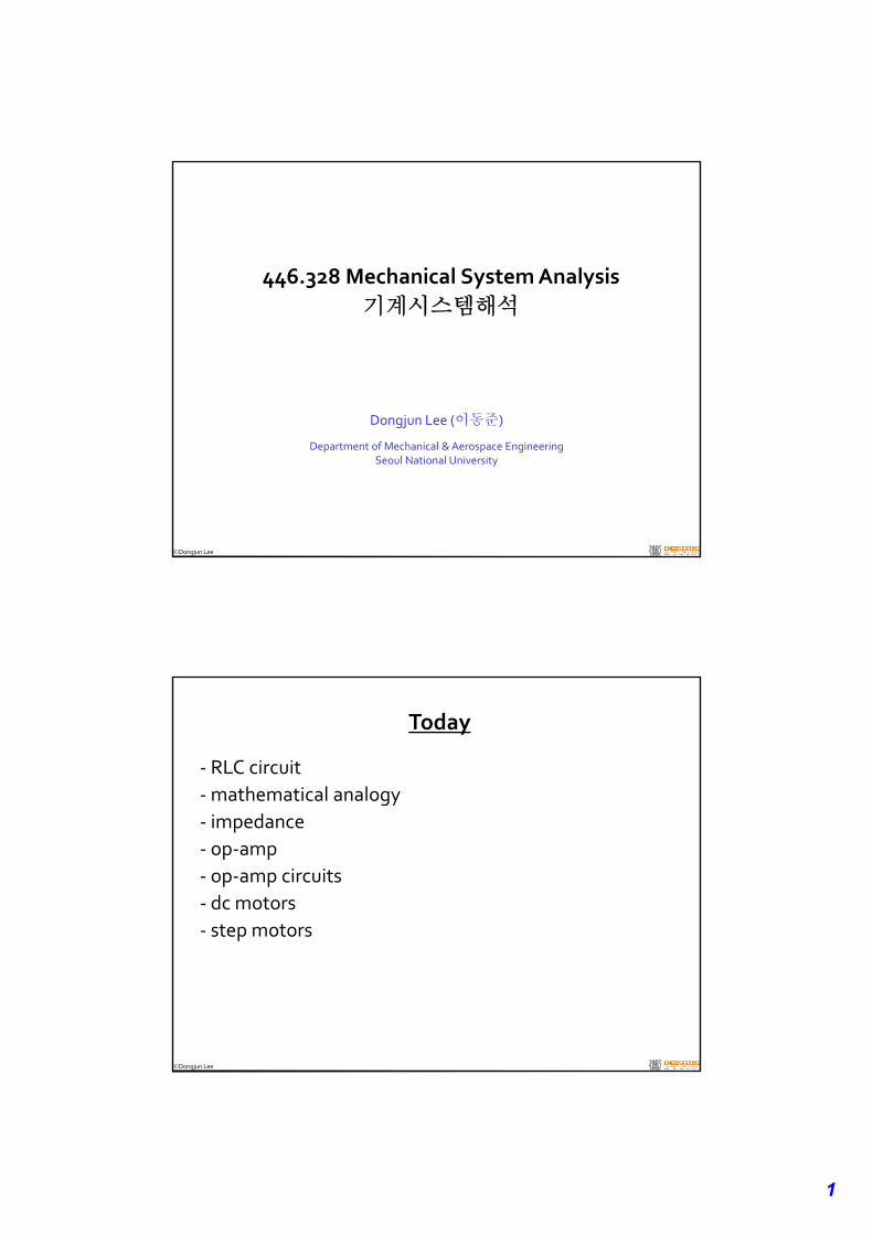
Today
‐ RLC circuit
‐mathematical analogy
‐ impedance
‐ op‐amp
‐ op‐amp circuits
‐ dc motors
‐ step motors
2
Dongjun Lee
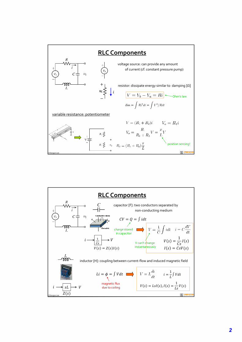
RLC Components
variable resistance: potentiometer
voltage source: can provide any amount
of current (cf. constant pressure pump)
resistor: dissipate energy similar to damping [Ω
Ohm’s law
position sensing!
Dongjun Lee
RLC Components
charge stored in capacitor
capacitor [F]: two conductors separated by
non‐conducting medium
V can’t change instantaneously
1
inductor [H]: coupling between current‐flow and induced magnetic field
magnetic flux due to coiling
1
,1
3
Dongjun Lee
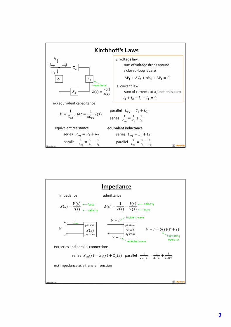
Kirchhoff’s Laws
1. voltage law:
sum of voltage drops around
a closed‐loop is zero
Δ Δ Δ Δ 0
2. current law:
sum of currents at a junction is zero
0ex) equivalent capacitance
1 1 parallel
series
equivalent resistance
series
parallel
equivalent inductance
series
parallel
impedance
Dongjun Lee
Impedance
impedance
ex) impedance as a transfer function
force
velocity
admittance
1
force
velocity
passive
circuit
system
+
‐
passive
circuit
system
incident wave
reflected wave
scatteringoperator
ex) series and parallel connections
series parallel
4
Dongjun Lee
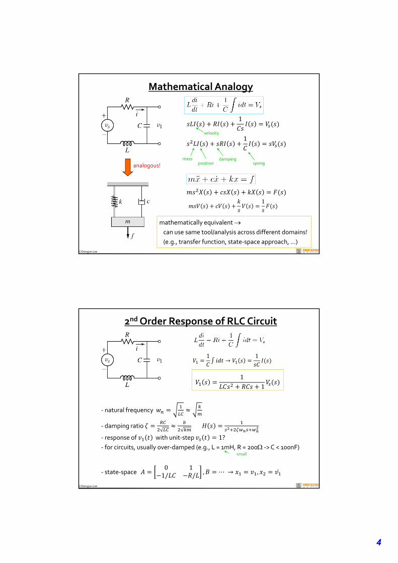
Mathematical Analogy
analogous! spring
1
dampingmassposition
1
velocity
mathematically equivalent can use same tool/analysis across different domains!
(e.g., transfer function, state‐space approach, …)
1
Dongjun Lee
2ndOrder Response of RLC Circuit
1→
1
11
‐ natural frequency
‐ damping ratio
‐ response of with unit‐step 1?‐ for circuits, usually over‐damped (e.g., L = 1mH, R = 200 ‐> C < 100nF)
‐ state‐space 0 11/ / , ⋯ → ,
small
5
Dongjun Lee
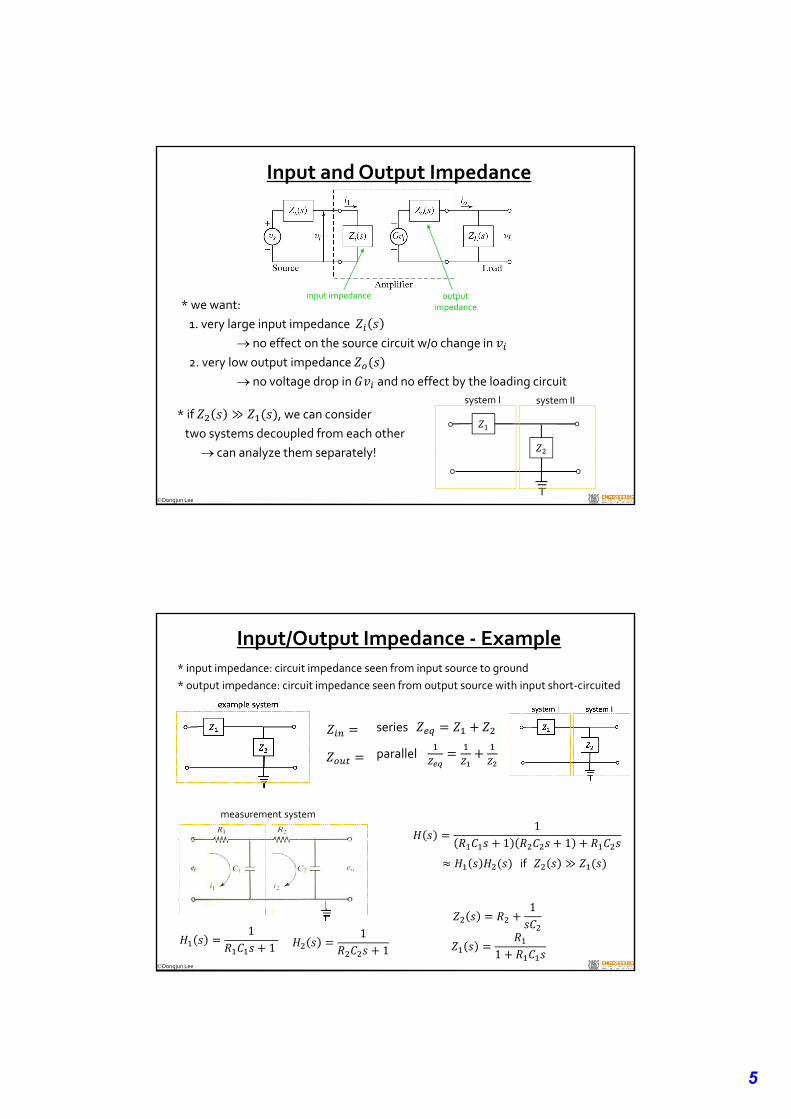
Input and Output Impedance
input impedance output impedance* we want:
1. very large input impedance
no effect on the source circuit w/o change in
2. very low output impedance
no voltage drop in and no effect by the loading circuit
* if ≫ , we can consider
two systems decoupled from each other
can analyze them separately!
system I system II
Dongjun Lee
Input/Output Impedance ‐ Example
11
11
1
1
series
parallel
11 1
if ≫
* input impedance: circuit impedance seen from input source to ground
* output impedance: circuit impedance seen from output source with input short‐circuited
measurement system
6
Dongjun Lee
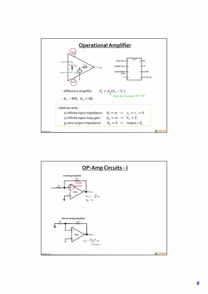
Operational Amplifier
‐ ideal op‐amp
1) infinite input impedance ∞ → 02) infinite open‐loop gain ∞ → 3) zero output impedance 0 →output =
‐ difference amplifier large open‐loop gain: 10 ~10
‐ : ~ Ω, 0Ω
Dongjun Lee
OP‐Amp Circuits ‐ I
virtual ground
7
Dongjun Lee
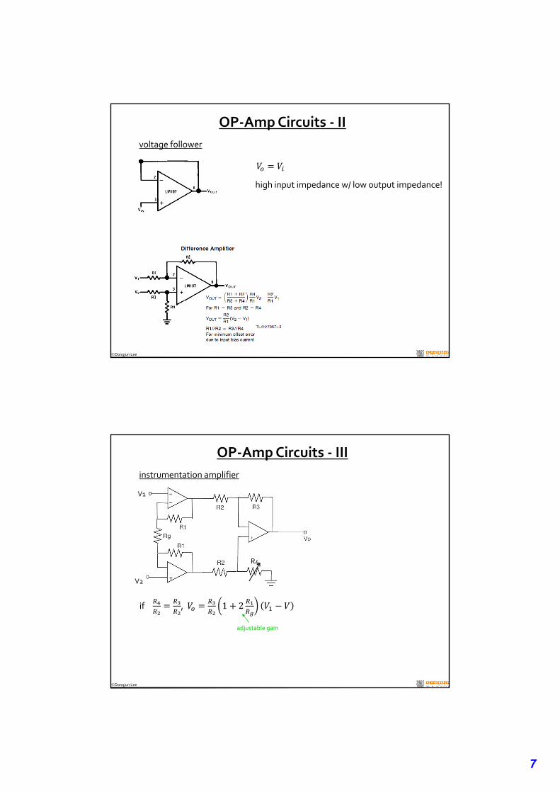
voltage follower
OP‐Amp Circuits ‐ II
high input impedance w/ low output impedance!
Dongjun Lee
V1
V2
R4
adjustable gain
if , 1 2
instrumentation amplifier
OP‐Amp Circuits ‐ III
8
Dongjun Lee
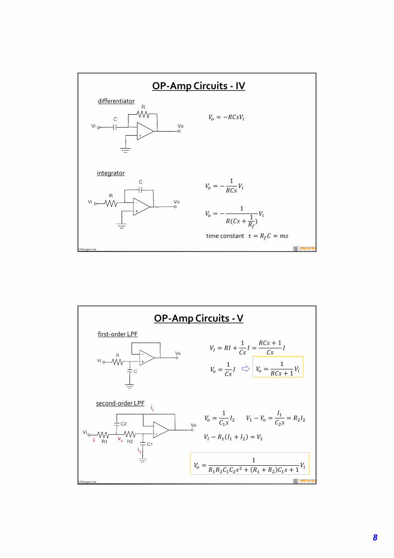
OP‐Amp Circuits ‐ IV
differentiator
integrator1
11
time constant
Dongjun Lee
first‐order LPF
OP‐Amp Circuits ‐V
second‐order LPF
11
11
1 1
1
v1
1
i2
i1
i
9
Dongjun Lee
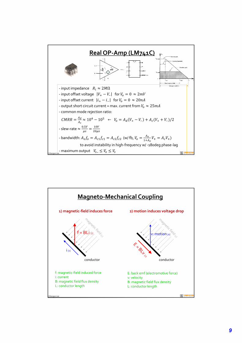
‐ input impedance 2 Ω‐ input offset voltage for 0 2‐ input offset current for 0 20‐ output short circuit current = max. current from 25‐ common mode rejection ratio:
10 10 ← /2
‐ slew‐rate .
‐ bandwidth: (w/ fb,
to avoid instability in high‐frequency w/ ‐180deg phase‐lag
‐maximum output _
Real OP‐Amp (LM741C)
Dongjun Lee
Magneto‐Mechanical Coupling
i [x]
conductor
1) magnetic‐field induces force 2) motion induces voltage drop
f = BLi [z]
f: magnetic‐field induced forcei: currentB: magnetic field flux densityL: conductor length
conductor
v: motion [x]
E: back emf (electromotive force)v: velocityB: magnetic field flux density L: conductor length
10
Dongjun Lee
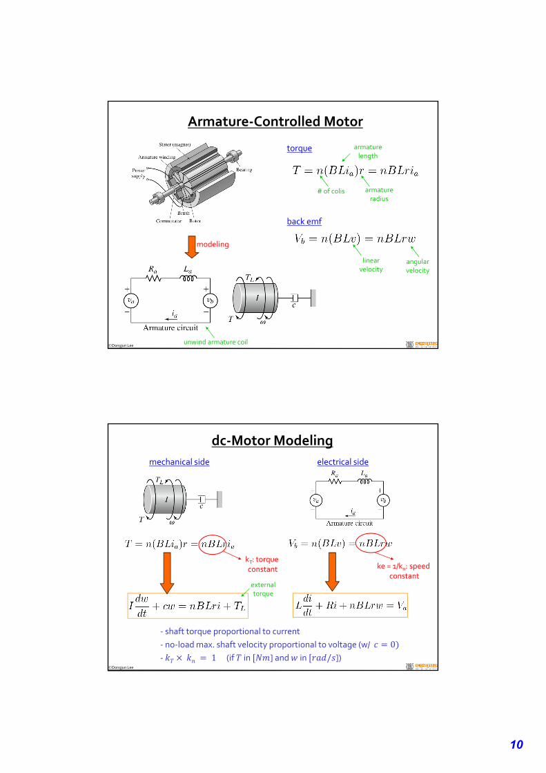
Armature‐Controlled Motor
torque
modeling
# of colis armatureradius
back emf
linearvelocity
angularvelocity
armaturelength
unwind armature coil
Dongjun Lee
dc‐Motor Modeling
mechanical side electrical side
externaltorque
‐ shaft torque proportional to current
‐ no‐load max. shaft velocity proportional to voltage (w/ 0‐ 1(if in ] and in / ])
kT: torque constant ke = 1/kn: speed
constant
11
Dongjun Lee
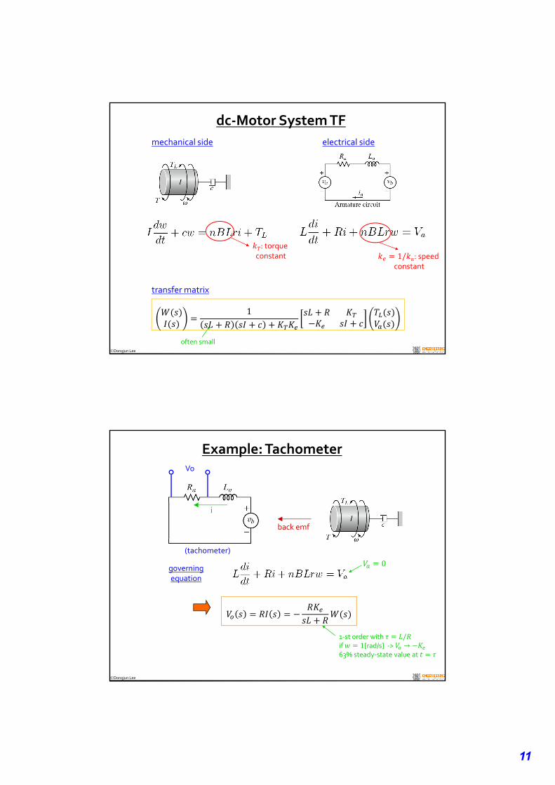
dc‐Motor System TF
mechanical side electrical side
often small
: torque constant 1/ : speed
constant
1
transfer matrix
Dongjun Lee
Example: Tachometer
back emf
governingequation
(tachometer)
i
Vo
1‐st order with /if 1[rad/s] ‐> →63% steady‐state value at
0
12
Dongjun Lee
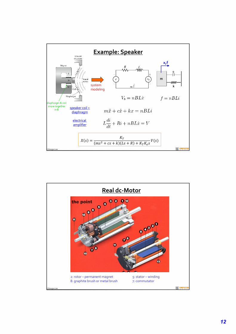
Example: Speaker
systemmodeling
m
k
c
x,f
speaker coil +diaphragm
electrical amplifier
diaphragm & coilmove together
in B
Dongjun Lee
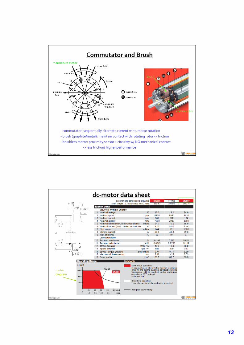
Real dc‐Motor
2: rotor – permanent magnet 5: stator – winding8: graphite brush or metal brush 7: commutator
13
Dongjun Lee
Commutator and Brush
‐ commutator: sequentially alternate current w.r.t. motor rotation
‐ brush (graphite/metal): maintain contact with rotating rotor ‐> friction
‐ brushless motor: proximity sensor + circuitry w/ NO mechanical contact
‐> less friction/ higher performance
* armature motor
brush
commutator
Dongjun Lee
dc‐motor data sheet
motor diagram
14
Dongjun Lee
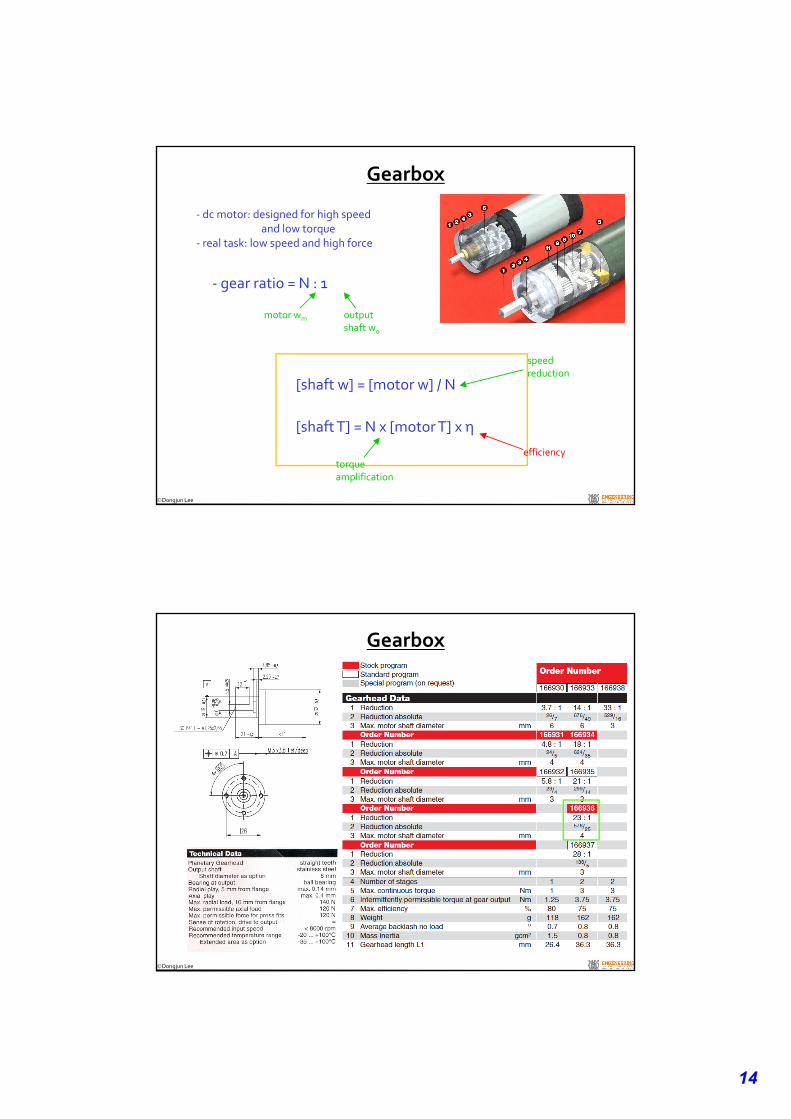
Gearbox
[shaft w] = [motor w] / N
[shaft T] = N x [motor T] x η
‐ dc motor: designed for high speed and low torque
‐ real task: low speed and high force
‐ gear ratio = N : 1
motor wm output shaft wo
speed reduction
torqueamplification
efficiency
Dongjun Lee
Gearbox
15
Dongjun Lee
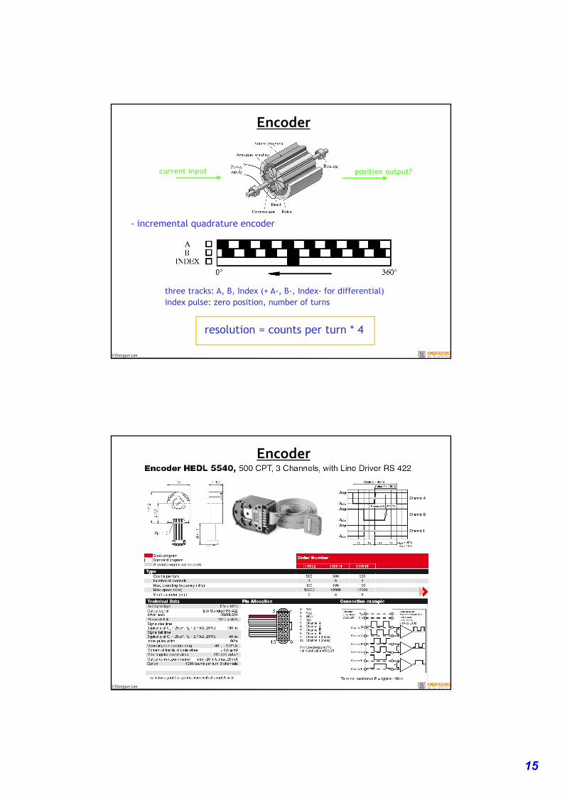
Encoder
- incremental quadrature encoder
three tracks: A, B, Index (+ A-, B-, Index- for differential)index pulse: zero position, number of turns
resolution = counts per turn * 4
current input position output?
Dongjun Lee
Encoder
16
Dongjun Lee
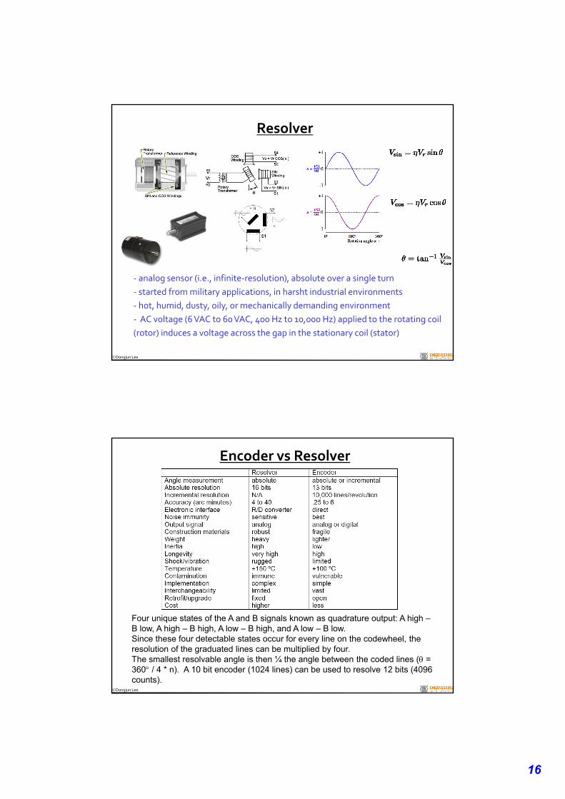
Resolver
‐ analog sensor (i.e., infinite‐resolution), absolute over a single turn
‐ started from military applications, in harsht industrial environments
‐ hot, humid, dusty, oily, or mechanically demanding environment
‐ AC voltage (6 VAC to 60 VAC, 400 Hz to 10,000 Hz) applied to the rotating coil
(rotor) induces a voltage across the gap in the stationary coil (stator)
Dongjun Lee
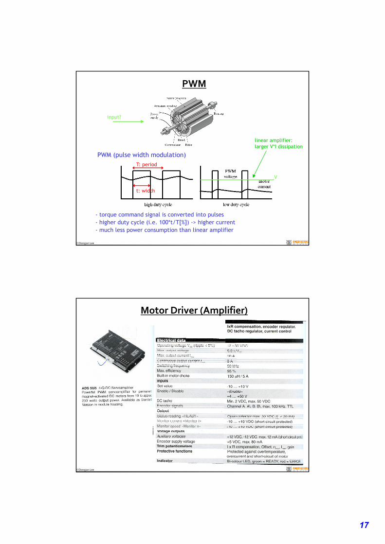
Encoder vs Resolver
Four unique states of the A and B signals known as quadrature output: A high –B low, A high – B high, A low – B high, and A low – B low.Since these four detectable states occur for every line on the codewheel, the resolution of the graduated lines can be multiplied by four.The smallest resolvable angle is then ¼ the angle between the coded lines ( = 360 / 4 * n). A 10 bit encoder (1024 lines) can be used to resolve 12 bits (4096 counts).
17
Dongjun Lee
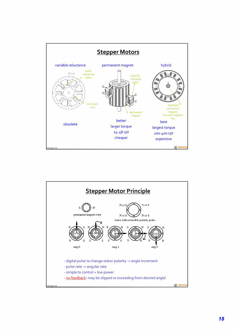
PWM
input?
PWM (pulse width modulation)
- torque command signal is converted into pulses- higher duty cycle (i.e. 100*t/T[%]) -> higher current - much less power consumption than linear amplifier
T: period
t: width
linear amplifier:larger V*I dissipation
V
Dongjun Lee
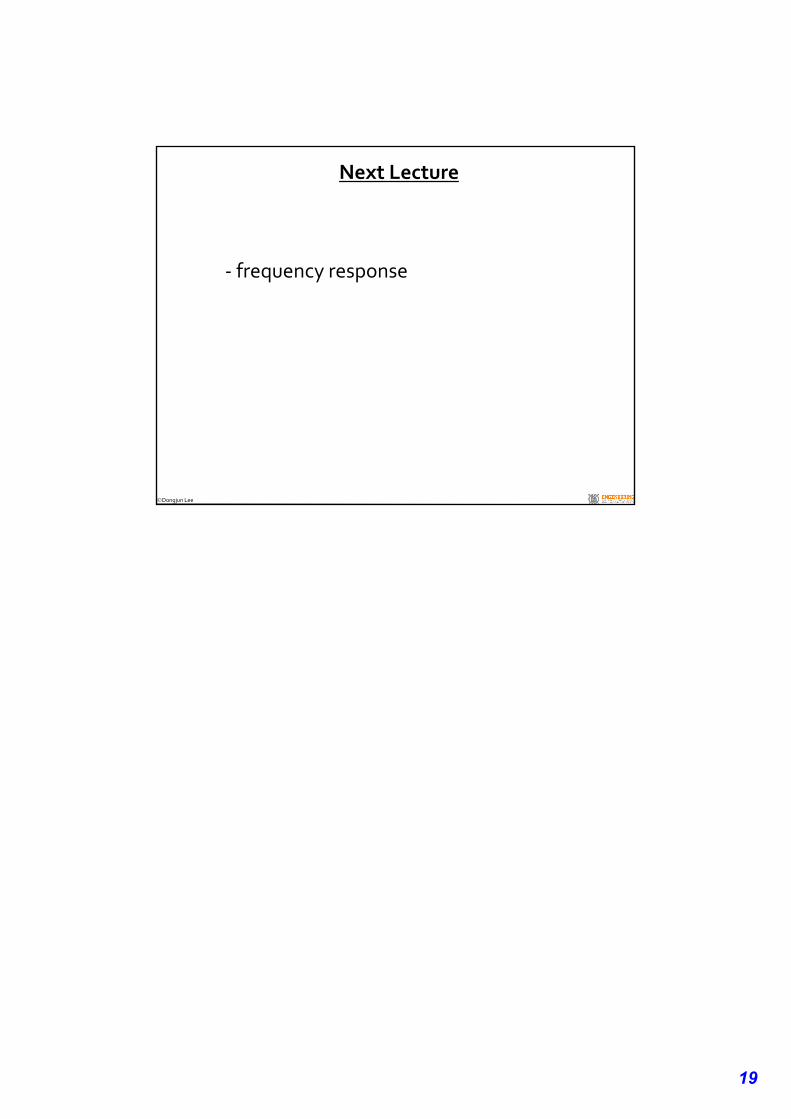
Motor Driver (Amplifier)
18
Dongjun Lee
Stepper Motors
variable reluctance
iron tooth core
permanent magnet hybrid
obsoletebetter
larger torque
24‐48 cpt
cheaper
best
largest torque
100‐400 cpt
expensive
permanentmagnet
polarity‐changingstator
tooth‐attracting
stator
tootheadpermanentmagnet:
focused magneticflux
Dongjun Lee
Stepper Motor Principle
‐ digital pulse to change stator polarity ‐> angle increment
‐ pulse rate ‐> angular rate
‐ simple to control + low power
‐ no feedback: may be slipped or exceeding from desired angle!
19
Dongjun Lee
Next Lecture
‐ frequency response