
1354e NotRegR241A en - genpowerusa.com This manual concerns the alternator A.V.R. which you have...
16
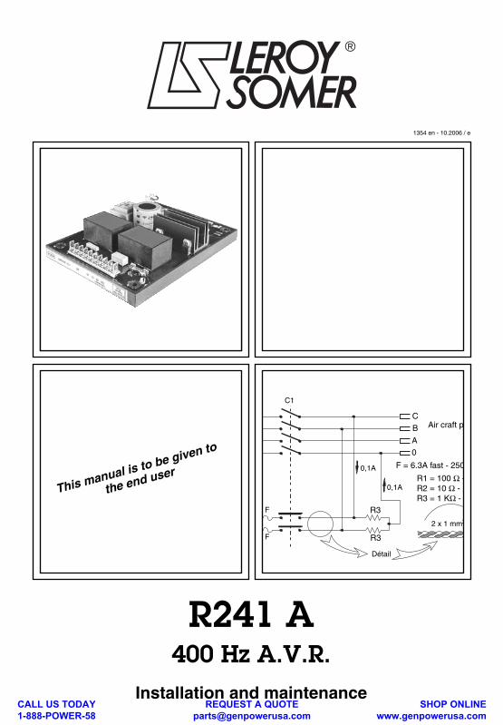
This manual is to be given to the end user 1354 en - 10.2006 / e R241 A 400 Hz A.V.R. Installation and maintenance Air craft p C B A 0,1A 0 0,1A R3 R3 C1 F F R1 = 100 Ω - R2 = 10 Ω - 1 R3 = 1 KΩ - Détail 2 x 1 mm 2 F = 6.3A fast - 250 CALL US TODAY 1-888-POWER-58 REQUEST A QUOTE [email protected] SHOP ONLINE www.genpowerusa.com
Transcript of 1354e NotRegR241A en - genpowerusa.com This manual concerns the alternator A.V.R. which you have...
This manual is to be given to
the end user
1354 en - 10.2006 / e
R241 A
400 Hz A.V.R.
Installation and maintenance
Air craft pC
B
A
0,1A
0
0,1A
R3
R3
C1
F
F
R1 = 100 Ω -R2 = 10 Ω - 1R3 = 1 KΩ -
Détail
2 x 1 mm2
F = 6.3A fast - 250
CALL US TODAY 1-888-POWER-58
REQUEST A QUOTE [email protected]
SHOP ONLINE www.genpowerusa.com
Installation and maintenance
R241 A
400 Hz A.V.R.
2
1354 en - 10.2006 / e
LEROY-SOMER
This manual concerns the alternator A.V.R. which you have just purchased.
We wish to draw your attention to the contents of this maintenance manual. By fol-lowing certain important points during installation, use and servicing of your A.V.R.,you can look forward to many years of trouble-free operation.
SAFETY MEASURES
Before using your machine for the first time,it is important to read the whole of thisinstallation and maintenance manual.
All necessary operations and interventionson this machine must be performed by aqualified technician.
Our technical support service will bepleased to provide any additional infor-mation you may require.
The various operations described in thismanual are accompanied by recommen-dations or symbols to alert the user topotential risks of accidents. It is vital thatyou understand and take notice of thefollowing warning symbols.
This A.V.R. can be incorporated in amachine marked C.E.
Note: LEROY-SOMER reserves the right tomodify the characteristics of its products atany time in order to incorporate the latesttechnological developments. The informationcontained in this document may therefore bechanged without notice.
Warning symbol for an operationcapable of damaging or destroying themachine or surround-ing equipment.
Warning symbol for general danger topersonnel.
Warning symbol for electrical danger topersonnel.
Copyright 2006 :MOTEURS LEROY-SOMERThis document is the property of :MOTEURS LEROY-SOMERIt may not be reproduced in any formwithout prior authorization.
All brands and models have been registe-red and patents applied for.
WARNINGWARNING
CALL US TODAY 1-888-POWER-58
REQUEST A QUOTE [email protected]
SHOP ONLINE www.genpowerusa.com
Installation and maintenance
R241 A
400 Hz A.V.R.
1354 en - 10.2006 / e
LEROY-SOMER
3
CONTENTS
1 - AUTOMATIC VOLTAGE REGULATOR............................................................................4
1.1 - Description...................................................................................................................41.2 - Features ......................................................................................................................41.3 - Function of adjustment pots ........................................................................................4
2 - CONNECTION OF VOLTAGE REGULATOR ..................................................................5
2.1 - Power lines ..................................................................................................................52.2 - Voltage sensing ..........................................................................................................52.3 - Voltage sensing across generator's output terminal ...................................................52.4 - Loss of sensing (protection) ........................................................................................5
3 - ADJUSTMENTS ................................................................................................................6
3.1 - Preliminary setting ......................................................................................................63.2 - Line voltage dip compensation ...................................................................................63.3 - Parallel operation (quadrature droop) .........................................................................7
4 - LIMITATION OF MAXIMUM EXCITATION CURRENT (EXCITATION CEILING) ...........8
5 - TRANSIENT VOLTAGE RECOVERY VARIATIONS .......................................................8
5.1 - Step loading ................................................................................................................85.2 - Unloading ....................................................................................................................8
6 - OUTLINES DRAWING ......................................................................................................9
7 - CONNECTION DIAGRAM ..............................................................................................10
8 - FACTORY ADJUSTMENT FORM (Sample) .................................................................11
9 - SPARE PARTS ...............................................................................................................12
9.1 - Designation ..............................................................................................................129.2 - Technical support service .........................................................................................129.3 - Optional items ...........................................................................................................129.4 - Repair .......................................................................................................................12
All such operations performed on the A.V.R. should be undertaken by personnel trainedin the commissioning, servicing and maintenance of electrical and mechanicalcomponents.
CALL US TODAY 1-888-POWER-58
REQUEST A QUOTE [email protected]
SHOP ONLINE www.genpowerusa.com
Installation and maintenance
R241 A
400 Hz A.V.R.
4
1354 en - 10.2006 / e
LEROY-SOMER
1 - AUTOMATIC VOLTAGE REGULATOR1.1 - Description
Supply to AVR is shunt or separate. It actsas a chopper (FET controlled) and has adouble action (with reversal of output cur-rent). It is very fast (less than 5 ms detec-tion time) and very accurate (±1%).EMI filters are built-in (suppresssion accor-ding VDE 0875 classK). According to moresevere regulations (émission, suceptibility)the AVR may be supplied in a shielded boxwith a plug connector It is totally encapsulated and designed tobe installed in a ventilated panel (ambient
≤
65 °C), (see outline draving page 9).Rated heat rejection : 35 W
1.2 - Features
- Power supply : 100 to 140 V AC for shuntoperation the supply is taken betweenlineand neutral for 115 / 200 V machine.Use a voltage transformer (secondary100 V - 10 A) for other voltages. Input fuse :6.3 A / fast.- Voltage sensing : (115 - 200 V)
400 Hz - 5 A(140 - 240 V)
- Output : Max. 10 A / 10 s. An internal ad-justable current limitation enables to adjustthe maximum excitation current between 4and 8 A.- Terminal strips : 1 set of 10 terminals (J1)and 1 set of 5 (J2) for 1/4" spade clips.- Adjustment means : 9 potentiometers with1/10" length slot to be set with a screwdriver.- C.T. input : For line voltage dip compen-sation or parallel operation. C.T. datas : se-condary current 1 A, 2 VA, class 1, (400 Hz).- 2 terminals for connection of remote volt :Adjustment pot 470
Ω
- 3 Watts
1.3 - Function of adjustment pots
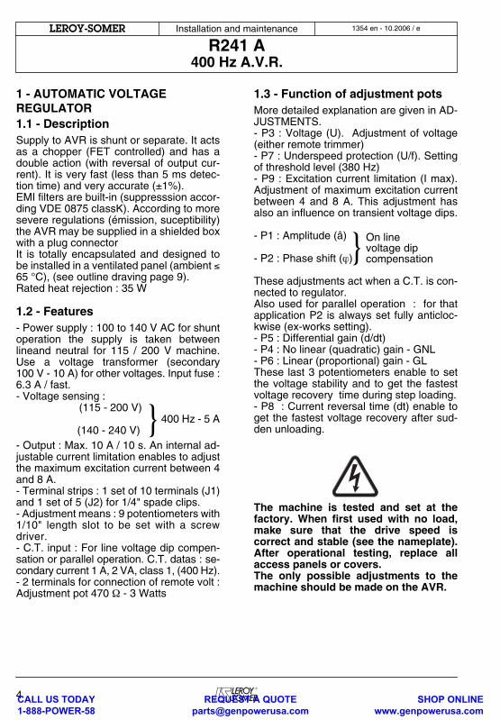
More detailed explanation are given in AD-JUSTMENTS.- P3 : Voltage (U). Adjustment of voltage(either remote trimmer)- P7 : Underspeed protection (U/f). Settingof threshold level (380 Hz)- P9 : Excitation current limitation (I max).Adjustment of maximum excitation currentbetween 4 and 8 A. This adjustment hasalso an influence on transient voltage dips.
- P1 : Amplitude (â)
- P2 : Phase shift (
ϕ
) These adjustments act when a C.T. is con-nected to regulator.Also used for parallel operation : for thatapplication P2 is always set fully anticloc-kwise (ex-works setting).- P5 : Differential gain (d/dt)- P4 : No linear (quadratic) gain - GNL- P6 : Linear (proportional) gain - GLThese last 3 potentiometers enable to setthe voltage stability and to get the fastestvoltage recovery time during step loading.- P8 : Current reversal time (dt) enable toget the fastest voltage recovery after sud-den unloading.
The machine is tested and set at thefactory. When first used with no load,make sure that the drive speed iscorrect and stable (see the nameplate).After operational testing, replace allaccess panels or covers.The only possible adjustments to themachine should be made on the AVR.
}
} On linevoltage dipcompensation
CALL US TODAY 1-888-POWER-58
REQUEST A QUOTE [email protected]
SHOP ONLINE www.genpowerusa.com
Installation and maintenance
R241 A
400 Hz A.V.R.
1354 en - 10.2006 / e
LEROY-SOMER
5
2 - CONNECTION OF VOLTAGE REGULATOR
(See diagram on page 10).The AVR is delivered to be installed in acontrol panel. Some precautions have totaken concerning the power line connec-tions (voltage dip, EMI), as well for the vol-tage sensing leads.
2.1 - Power lines
- Input/Output :The E.M. radiation may be limited by using2 pairs of twisted wires or shielded audio-type cables. Voltage dip (for a rated currentin the range 2 to 4 A according generatorrating) : should be limited to 10 V total (DCside + AC 400 Hz side).
2.2 - Voltage sensing
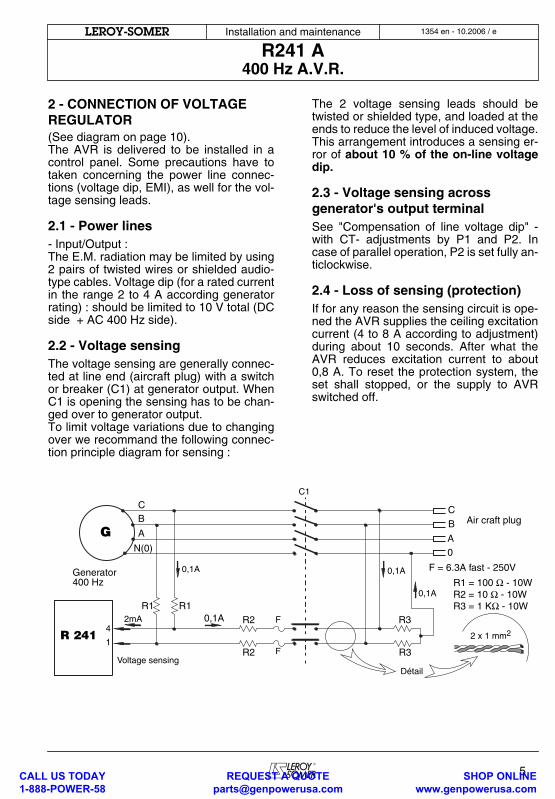
The voltage sensing are generally connec-ted at line end (aircraft plug) with a switchor breaker (C1) at generator output. WhenC1 is opening the sensing has to be chan-ged over to generator output.To limit voltage variations due to changingover we recommand the following connec-tion principle diagram for sensing :
The 2 voltage sensing leads should betwisted or shielded type, and loaded at theends to reduce the level of induced voltage.This arrangement introduces a sensing er-ror of
about 10 % of the on-line voltagedip.
2.3 - Voltage sensing across generator's output terminal
See "Compensation of line voltage dip" -with CT- adjustments by P1 and P2. Incase of parallel operation, P2 is set fully an-ticlockwise.
2.4 - Loss of sensing (protection)
If for any reason the sensing circuit is ope-ned the AVR supplies the ceiling excitationcurrent (4 to 8 A according to adjustment)during about 10 seconds. After what theAVR reduces excitation current to about0,8 A. To reset the protection system, theset shall stopped, or the supply to AVRswitched off.
G A
BC
Air craft plugC
B
A
0,1A
0
0,1A
R3
R3
C1
F
F
R2
R2
0,1A
R1R12mA 0,1A
N(0)
Generator400 Hz R1 = 100 Ω - 10W
R2 = 10 Ω - 10WR3 = 1 KΩ - 10W
4
1R 241
Voltage sensingDétail
2 x 1 mm2
F = 6.3A fast - 250V
CALL US TODAY 1-888-POWER-58
REQUEST A QUOTE [email protected]
SHOP ONLINE www.genpowerusa.com
Installation and maintenance
R241 A
400 Hz A.V.R.
6
1354 en - 10.2006 / e
LEROY-SOMER
3 - ADJUSTMENTS
The voltage regulators delivered togetherwith the alternators have been adjusted atworks,
at the exception of potentiome-ters P1 and P2
(line voltage dip compen-sation) which are fully CCW (zero setting). A form (see page 11) is supplied with eachmachine indicating all the potentiometerspositions set in factory. When installing aspare AVR, set the potentiometers as indi-cated on this form.
"Line voltage dip compensation has to bereadjusted as indicated further in par 3.2".
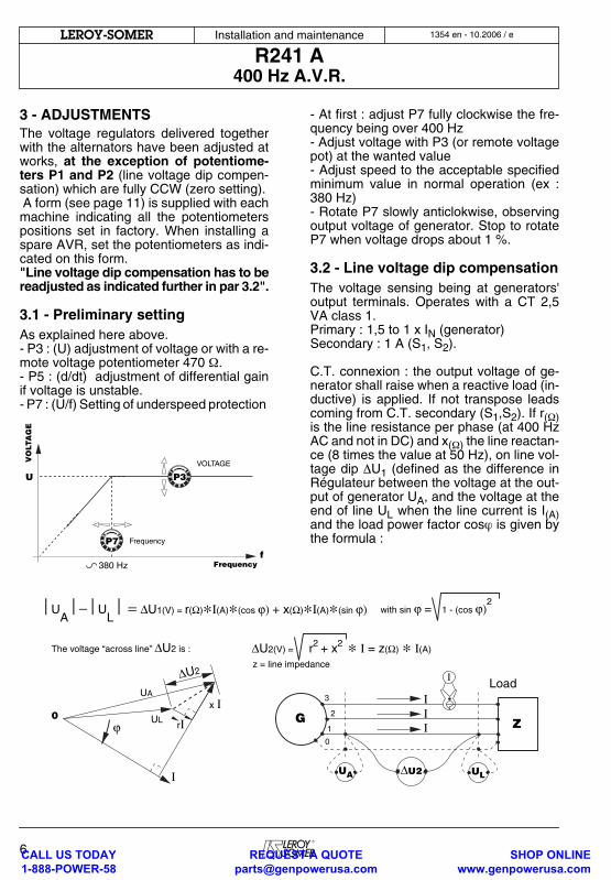
3.1 - Preliminary setting
As explained here above.- P3 : (U) adjustment of voltage or with a re-mote voltage potentiometer 470
Ω
.- P5 : (d/dt) adjustment of differential gainif voltage is unstable.- P7 : (U/f) Setting of underspeed protection
- At first : adjust P7 fully clockwise the fre-quency being over 400 Hz- Adjust voltage with P3 (or remote voltagepot) at the wanted value- Adjust speed to the acceptable specifiedminimum value in normal operation (ex :380 Hz)- Rotate P7 slowly anticlokwise, observingoutput voltage of generator. Stop to rotateP7 when voltage drops about 1 %.
3.2 - Line voltage dip compensation
The voltage sensing being at generators'output terminals. Operates with a CT 2,5VA class 1.Primary : 1,5 to 1 x I
N
(generator)Secondary : 1 A (S
1
, S
2
).
C.T. connexion : the output voltage of ge-nerator shall raise when a reactive load (in-ductive) is applied. If not transpose leadscoming from C.T. secondary (S
1
,S
2
). If r
(
Ω
)
is the line resistance per phase (at 400 HzAC and not in DC) and x
(
Ω
)
the line reactan-ce (8 times the value at 50 Hz), on line vol-tage dip
Δ
U
1
(defined as the difference inRégulateur between the voltage at the out-put of generator U
A
, and the voltage at theend of line U
L
when the line current is I
(A)
and the load power factor cos
ϕ
is given bythe formula :
VO
LTA
GE
fFrequency
U P3
P7
380 Hz
VOLTAGE
Frequency
ΔU2(V) = r2 + x2 ∗ Ι = z(Ω) ∗ Ι(A)
z = line impedance
G Z
UA ULΔU2
1
2
3 ΙΙΙ
Load
⎮UA
⎮−⎮UL⎮ = ΔU1(V) = r(Ω)∗Ι(A)∗(cos ϕ) + x(Ω)∗Ι(A)∗(sin ϕ) with sin ϕ = 1 - (cos ϕ)
2
The voltage “across line” ΔU2 is :
0
Ι
0
Ι
ULrΙ
UA
x Ι
ϕ
ΔU2
CALL US TODAY 1-888-POWER-58
REQUEST A QUOTE [email protected]
SHOP ONLINE www.genpowerusa.com
Installation and maintenance
R241 A
400 Hz A.V.R.
1354 en - 10.2006 / e
LEROY-SOMER
7
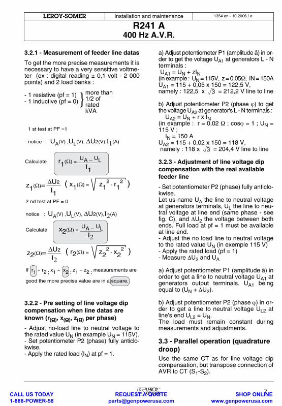
3.2.1 - Measurement of feeder line datas
To get the more precise measurements it isnecessary to have a very sensitive voltme-ter (ex : digital reading ± 0,1 volt - 2 000points) and 2 load banks :
- 1 resistive (pf = 1)- 1 inductive (pf = 0)
3.2.2 - Pre setting of line voltage dip compensation when line datas are known (r
(
ΩΩΩΩ
)
, x
(
ΩΩΩΩ
)
, z
(
ΩΩΩΩ
)
per phase)
- Adjust no-load line to neutral voltage tothe rated value U
N
(in example U
N
= 115V).- Set potentiometer P2 (phase) fully anticlo-kwise.- Apply the rated load (I
N
) at pf = 1.
a) Adjust potentiometer P1 (amplitude â) in or-der to get the voltage U
A1
at generators L - Nterminals : U
A1
= U
N
+ zI
N
(in example : U
N
= 115V, z = 0,05
Ω
, IN = 150AU
A1
= 115 + 0,05 x 150 = 122,5 V, namely : 122,5 x = 212,2 V line to line
b) Adjust potentiometer P2 (phase
ϕ
) to getthe voltage U
A2
at generator's L - N terminals : U
A2
= U
N
+ r x I
N
(in example : r = 0,02
Ω
; cos
ϕ
= 1 ; U
N
=115 V ; I
N
= 150 AU
A2
= 115 + 0,02 x 150 = 118 V, namely : 118 x = 204,4 V line to line
3.2.3 - Adjustment of line voltage dip compensation with the real available feeder line
- Set potentiometer P2 (phase) fully anticlo-kwise.Let us name U
A
the line to neutral voltageat generators terminals, U
L
the line to neu-tral voltage at line end (same phase - seefig. C), and
Δ
U
2
the voltage between bothends. Full load at pf = 1 must be availableat line end. - Adjust the no load line to neutral voltageto the rated value U
N
(in exemple 115 V)- Apply the rated load (pf = 1)- Measure
Δ
U
2
and U
A
a) Adjust potentiometer P1 (amplitude â) inorder to get a line to neutral voltage U
A1
atgenerators output terminals. U
A1
beingequal to (U
N
+
Δ
U
2
). b) Adjust potentiometer P2 (phase
ϕ
) in or-der to get a line to neutral voltage U
L2
atline's end U
L2
= U
N
.The load must remain constant duringmeasurements and adjustments.
3.3 - Parallel operation (quadrature droop)
Use the same CT as for line voltage dipcompensation, but transpose connection ofAVR to CT (S
1
-S
2
).
}more than1/2 ofratedkVA
1 st test at PF =1
notice : UA(V) ,UL(V), ΔU2(V),Ι1(A)
Calculate r1(Ω) = UA _ UL
z1(Ω)= ΔU2
Ι1( x1(Ω) = z1
2 - r1
2 )
Ι1
2 nd test at PF = 0
notice : UA(V) ,UL(V), ΔU2(V),Ι2(A)
Calculate x2(Ω) =
UA _ UL
If r1 ≈ r2 ; x1 ≈ x2 ; z1 ≈ z2 ; measurements are
good the more precise value are in a square.
Ι2
z2(Ω)= ΔU2
Ι2( r2(Ω) = z2
2 - x2
2 )
3
3
CALL US TODAY 1-888-POWER-58
REQUEST A QUOTE [email protected]
SHOP ONLINE www.genpowerusa.com
Installation and maintenance
R241 A
400 Hz A.V.R.
8
1354 en - 10.2006 / e
LEROY-SOMER
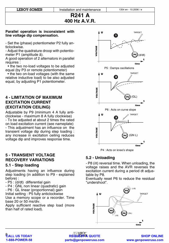
Parallel operation is inconsistent withline voltage dip compensation.
- Set the (phase) potentiometer P2 fully an-ticlockwise.- Adjust the quadrature droop with potentio-meter P1 (amplitude â). A good operation of 2 alternators in parallelrequires : • the two no-load voltages to be adjustedequal (by P3 or remote potentiometer) • the two on-load voltages (with the samerelative inductive load) to be also adjustedequal, by adjusting P1 potentiometer.
4 - LIMITATION OF MAXIMUM EXCITATION CURRENT (EXCITATION CEILING)Adjustable by P9 (minimum 4 A fully anti-clockwise - maximum 8 A fully clockwise)- To be adjusted at about 2 times the ratedon load excitation current (see nameplate)- This adjustment has an influence on thetransient voltage dip during step loading :any increase in excitation ceiling reducesvoltage dip and improves response time.
5 - TRANSIENT VOLTAGE RECOVERY VARIATIONS5.1 - Step loadingAdjustments having an influence duringstep loading (in addition to P9 - explainedbefore) :- P5 : (d/dt) differential gain- P4 : GNL non linear (quadratic) gain- P6 : GL linear (proportionnal) gainInitial setting : P5 fully anticlockwiseUse a memory scope or a recorder. Timebase 20 or 50 ms/div.Apply sufficient reactive step load (morethan half of rated load).
5.2 - Unloading- P8 (δt) reversal time. When unloading, thevoltage raises and the AVR reverses theexcitation current during a period dt adjus-table by P8. Eventually reset P6 to reduce the residual"undershoot".
1
P5VO
LTA
GE
t
TARGET
time
U
(d/dt)
P5 : Damps oscillations
2
P6
t
TARGET
time
U
VO
LTA
GE
(GL)
P6 : Acts on curve slope
3
P4
t
TARGET
time
U
VO
LTA
GE
(GN L)
P4 : Acts on knee’s shape
P6VO
LTA
GE
t
TARGET
time
U
P8
P8(+δt)
(-δt)(GL)
CALL US TODAY 1-888-POWER-58
REQUEST A QUOTE [email protected]
SHOP ONLINE www.genpowerusa.com

Installation and maintenance
R241 A400 Hz A.V.R.
1354 en - 10.2006 / eLEROY-SOMER
9
6 - OUTLINES DRAWING
R 241 A.V.R.
115
175
140
200
54
4 holes Ø 5,8
18
CURRENTTRANSFORMER 96
9682
7595
105
8288
4 holes Ø6x8
8
8
CALL US TODAY 1-888-POWER-58
REQUEST A QUOTE [email protected]
SHOP ONLINE www.genpowerusa.com
Installation and maintenance
R241 A400 Hz A.V.R.
10
1354 en - 10.2006 / eLEROY-SOMER
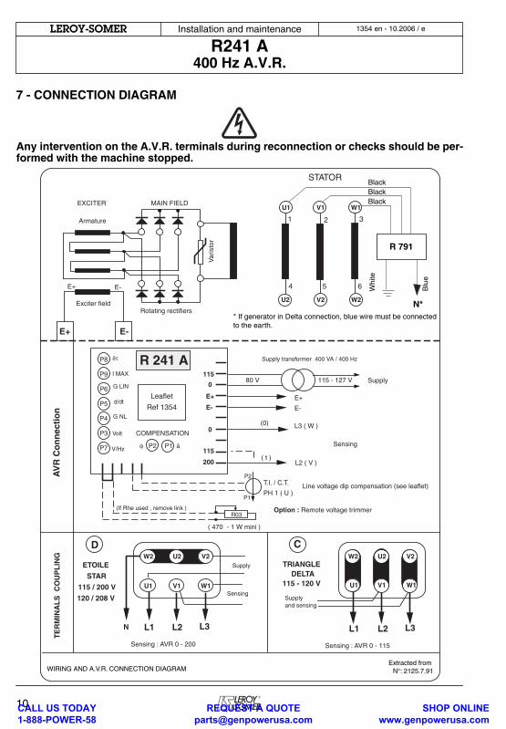
7 - CONNECTION DIAGRAM
Any intervention on the A.V.R. terminals during reconnection or checks should be per-formed with the machine stopped.
EXCITER
Armature
E+ E-
Exciter fieldRotating rectifiers
Var
isto
r
STATOR
MAIN FIELD
1
4
U1
U2
2
5
V1
V2
3
6
W1
W2
E- E+
TE
RM
INA
LS
CO
UP
LIN
GA
VR
Co
nn
ecti
on
Option : Remote voltage trimmer(If Rhe used , remove link )
Sensing : AVR 0 - 200
L3 ( W )
L2 ( V )
E+
E-
Supply
E+
E-
0
115
200
115
0
P8
P9
P6
P5
P4
P3
P7
δτ
I MAX
G LIN
G NL
d/dt
Volt
V/Hz
COMPENSATION
P2 P1φ â
R 241 A
Sensing
(0)
( t )
R03
P2
P1
T.I. / C.T.
PH 1 ( U )Line voltage dip compensation (see leaflet)
80 V
( 470 - 1 W mini )
115 - 127 V
TRIANGLE DELTA
115 - 120 V
L1 L2 L3
U1 V1
V2U2W2
W1
Supplyand sensing
L1 L2 L3
U1 V1 W1
V2U2W2
N
Supply
Sensing
CD
ETOILE
STAR
115 / 200 V
120 / 208 V
Sensing : AVR 0 - 115
Supply transformer 400 VA / 400 Hz
Leaflet
Ref 1354
WIRING AND A.V.R. CONNECTION DIAGRAMExtracted from
N°: 2125.7.91
R 791
N*
BlackBlackBlack
Whi
te
Blu
e
* If generator in Delta connection, blue wire must be connectedto the earth.
CALL US TODAY 1-888-POWER-58
REQUEST A QUOTE [email protected]
SHOP ONLINE www.genpowerusa.com
Installation and maintenance
R241 A400 Hz A.V.R.
1354 en - 10.2006 / eLEROY-SOMER
11
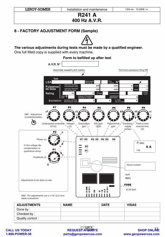
8 - FACTORY ADJUSTMENT FORM (Sample)
The various adjustments during tests must be made by a qualified engineer.One full filled copy is supplied with every machine.
Form to befilled up after test
ADJUSTMENTS NAME DATE VISASDone by :Checked by :Quality control :
TypeType
LSALSA Bob inageBob inageWindingWinding
serv ice secoursserv ice secoursstand-by dutystand-by duty
PhasePhase
PuissancePuissancede basede base
RatingRatingCos Cos P.F.P.F.
serv ice cont inuserv ice cont inucont inuous dutycont inuous duty
Fi lsFi lsLeadsLeads N°N°
AmbAmb
AmbAmb
Connect ionConnect ion tr /mntr /mnr.p.mr.p.m
rendementrendementef f ic iencyeff ic iency
classe d ' isolat ionclasse d ' isolat ioninsulat ion c lassinsulat ion c lass
à v ideà v ideat no loadat no load
serv ice cont inuserv ice cont inucont inuous dutycont inuous dutyExcitationExcitation
%
HzHz V
kWkW
kWkW
A
A
°C°C
°C°C
AV A
kVAkVA
kVAkVA
P7 P3 P4 P5 P6 P9 P8
P2
P1
11
5 V
0 VE+E-
0V
11
5 V
20
0 V
P7 P3 P4 P5 P6 P9 P8
P2
P1
FUSE
P. exc
i.e.
Serial number
(6.3A fast)
6 A
AVR
R241Adjustments to be done on site
NB2 : For adjustments use a 1/10” (2,5 mm)blade screwdriver.
NB1 : Adjustmentof potentiometers :
In line voltage dipcompensation orquadrature droop
MACHINE NAMEPLATE DATAS Technical assistance filing NR
Phase (ϕ)
Underspeed protection(V/Hz)
Voltage(U)
Quadraturegain
Diff. gain(d/dt)
Proportionalgain
Excitationceiling(I max)
Field currentreversal time
(δt)
+
0
+F +U +t4A8A
0
+Amplitude (â)
A.V.R. N°
CALL US TODAY 1-888-POWER-58
REQUEST A QUOTE [email protected]
SHOP ONLINE www.genpowerusa.com
Installation and maintenance
R241 A400 Hz A.V.R.
12
1354 en - 10.2006 / eLEROY-SOMER
9 - SPARE PARTS9.1 - Designation
9.2 - Technical support serviceOur technical support service will be happyto provide any information you require.
When ordering spare parts, you should in-dicate the complete machine type, its serialnumber and the information indicated onthe nameplate.
Part numbers should be identified fromthe exploded views and their descriptionin the parts list.Our extensive network of "service stations"can dispatch the necessary parts withoutdelay.To ensure correct operation and the safetyof our machines, we recommend the use oforiginal manufacture spare parts.In the event of failure to comply with this ad-vice, the manufacturer cannot be held res-ponsible for any damage.
9.3 - Optional items- Remote voltage trimmer : 470 Ω, 3 W.- Current transformer /1A according to no-minal voltage.- Shielded box.
9.4 - RepairThe A.V.R. R 241 , totally encapsulated isnot repairable. (See Alternator maintenan-ce book).
After operational testing, replace allaccess panels or covers.
Description Type Code
A.V.R. R 241 AEM 220 RE 2
CALL US TODAY 1-888-POWER-58
REQUEST A QUOTE [email protected]
SHOP ONLINE www.genpowerusa.com
Installation and maintenance
R241 ANOTES
1354 en - 10.2006 / eLEROY-SOMER
13CALL US TODAY 1-888-POWER-58
REQUEST A QUOTE [email protected]
SHOP ONLINE www.genpowerusa.com
Installation and maintenance
R241 ANOTES
14
1354 en - 10.2006 / eLEROY-SOMER
CALL US TODAY 1-888-POWER-58
REQUEST A QUOTE [email protected]
SHOP ONLINE www.genpowerusa.com
MOTEURS LEROY-SOMER 16015 ANGOULÊME CEDEX - FRANCE
338 567 258 RCS ANGOULÊMES.A. au capital de 62 779 000 €
www.leroy-somer.com
CALL US TODAY 1-888-POWER-58
REQUEST A QUOTE [email protected]
SHOP ONLINE www.genpowerusa.com