
11 maging - Stanford Universityisl.stanford.edu/~abbas/ee392b/lect11.pdf · • iffn d metamers...
22
Lecture Notes 11 Introduction to Color Imaging • Color filter options • Color processing • Color interpolation (demozaicing) • White balancing • Color correction EE 392B: Color Imaging 11-1
Transcript of 11 maging - Stanford Universityisl.stanford.edu/~abbas/ee392b/lect11.pdf · • iffn d metamers...
Lecture Notes 11
Introduction to Color Imaging
• Color filter options• Color processing• Color interpolation (demozaicing)• White balancing• Color correction
EE 392B: Color Imaging 11-1
Preliminaries
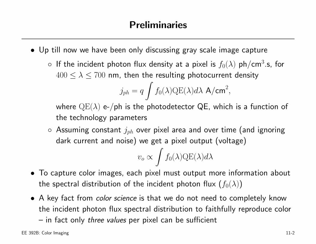
• Up till now we have been only discussing gray scale image capture
◦ If the incident photon flux density at a pixel is f0(λ) ph/cm3.s, for400 ≤ λ ≤ 700 nm, then the resulting photocurrent density
jph = q
∫f0(λ)QE(λ)dλ A/cm2,
where QE(λ) e-/ph is the photodetector QE, which is a function ofthe technology parameters
◦ Assuming constant jph over pixel area and over time (and ignoringdark current and noise) we get a pixel output (voltage)
vo ∝∫
f0(λ)QE(λ)dλ
• To capture color images, each pixel must output more information aboutthe spectral distribution of the incident photon flux (f0(λ))
• A key fact from color science is that we do not need to completely knowthe incident photon flux spectral distribution to faithfully reproduce color– in fact only three values per pixel can be sufficient
EE 392B: Color Imaging 11-2
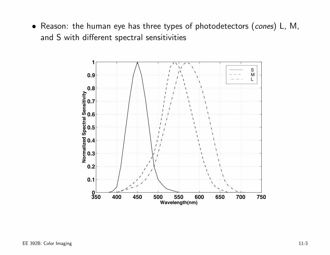
• Reason: the human eye has three types of photodetectors (cones) L, M,and S with different spectral sensitivities
350 400 450 500 550 600 650 700 7500
0.1
0.2
0.3
0.4
0.5
0.6
0.7
0.8
0.9
1
Wavelength(nm)
Nor
mal
ized
Spe
ctra
l Sen
sitiv
ity
SML
EE 392B: Color Imaging 11-3
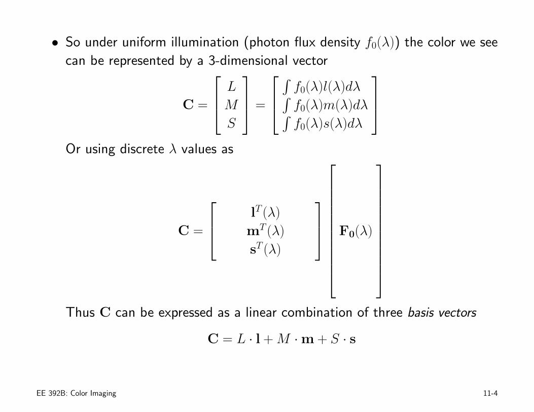
• So under uniform illumination (photon flux density f0(λ)) the color we seecan be represented by a 3-dimensional vector
C =
⎡
⎢⎣LMS
⎤
⎥⎦ =
⎡
⎢⎣
∫f0(λ)l(λ)dλ∫f0(λ)m(λ)dλ∫f0(λ)s(λ)dλ
⎤
⎥⎦
Or using discrete λ values as
C =
⎡
⎢⎣lT (λ)mT (λ)sT (λ)
⎤
⎥⎦
⎡
⎢⎢⎢⎢⎢⎢⎢⎢⎢⎢⎣
F0(λ)
⎤
⎥⎥⎥⎥⎥⎥⎥⎥⎥⎥⎦
Thus C can be expressed as a linear combination of three basis vectors
C = L · l + M · m + S · s
EE 392B: Color Imaging 11-4
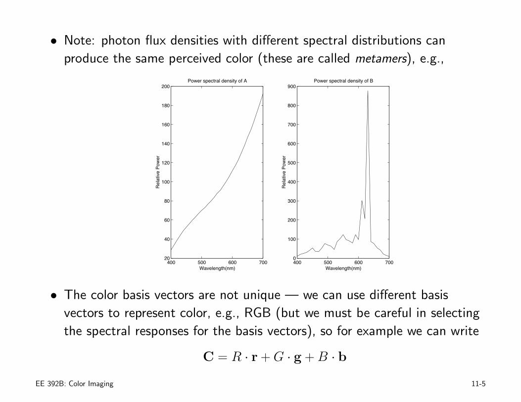
• Note: photon flux densities with different spectral distributions canproduce the same perceived color (these are called metamers), e.g.,
400 500 600 70020
40
60
80
100
120
140
160
180
200Power spectral density of A
Wavelength(nm)
Rel
ativ
e Po
wer
400 500 600 7000
100
200
300
400
500
600
700
800
900Power spectral density of B
Wavelength(nm)
Rel
ativ
e Po
wer
• The color basis vectors are not unique — we can use different basisvectors to represent color, e.g., RGB (but we must be careful in selectingthe spectral responses for the basis vectors), so for example we can write
C = R · r + G · g + B · b
EE 392B: Color Imaging 11-5
• C can be transformed from one basis vector representation to another (orfrom one color space to another) using a 3 × 3 matrix (more on this later)
• To get the three values from a pixel, color filters with different spectralresponses are used, e.g., R, G, B filters
• So if we denote the R filter response by φR(λ), the R output from a pixelwith photon flux density f0(λ) is
voR ∝∫
f0(λ)η(λ)φR(λ)dλ
and similarly for the other filters
• The “camera” RGB spectral responses are the products of each filter’sresponse and the photodetector spectral response, i.e., φR(λ)η(λ), . . . etc.
EE 392B: Color Imaging 11-6
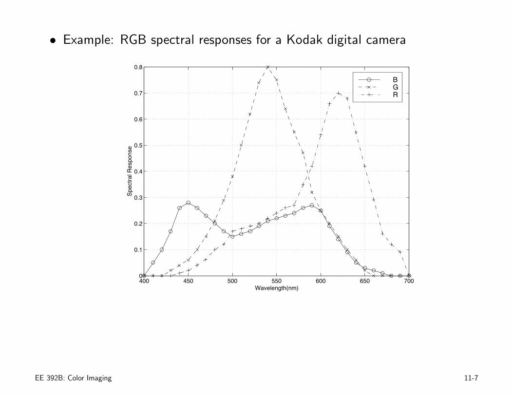
• Example: RGB spectral responses for a Kodak digital camera
400 450 500 550 600 650 7000
0.1
0.2
0.3
0.4
0.5
0.6
0.7
0.8
Wavelength(nm)
Spec
tral R
espo
nse
BGR
EE 392B: Color Imaging 11-7
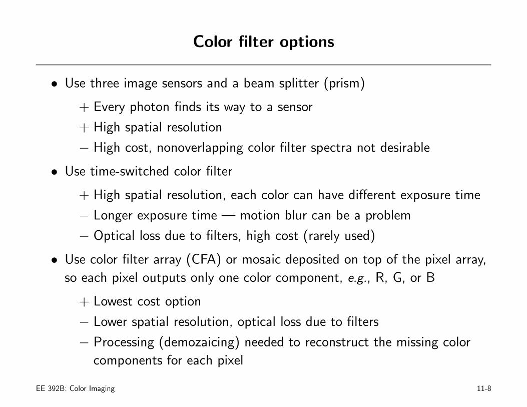
Color filter options
• Use three image sensors and a beam splitter (prism)
+ Every photon finds its way to a sensor
+ High spatial resolution
− High cost, nonoverlapping color filter spectra not desirable
• Use time-switched color filter
+ High spatial resolution, each color can have different exposure time
− Longer exposure time — motion blur can be a problem
− Optical loss due to filters, high cost (rarely used)
• Use color filter array (CFA) or mosaic deposited on top of the pixel array,so each pixel outputs only one color component, e.g., R, G, or B
+ Lowest cost option
− Lower spatial resolution, optical loss due to filters
− Processing (demozaicing) needed to reconstruct the missing colorcomponents for each pixel
EE 392B: Color Imaging 11-8
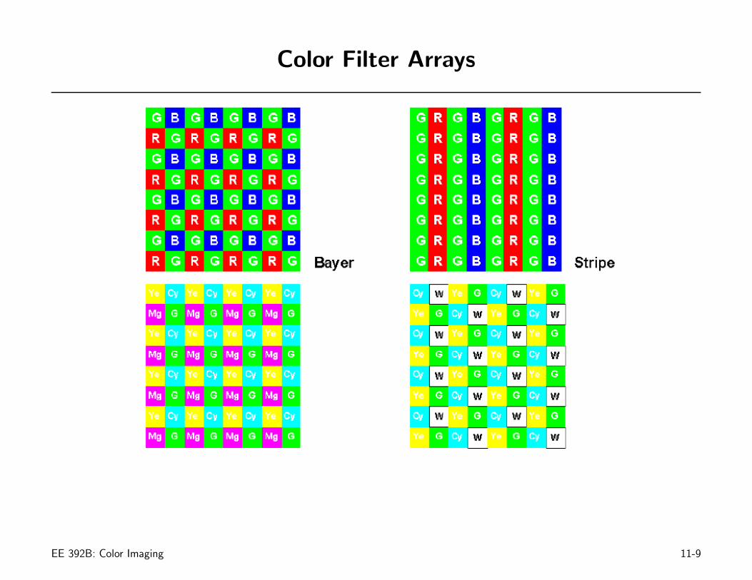
Color Filter Arrays
EE 392B: Color Imaging 11-9
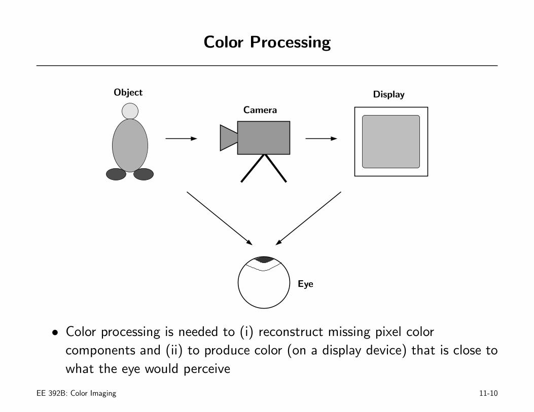
Color Processing
Object
Camera
Display
Eye
• Color processing is needed to (i) reconstruct missing pixel colorcomponents and (ii) to produce color (on a display device) that is close towhat the eye would perceive
EE 392B: Color Imaging 11-10
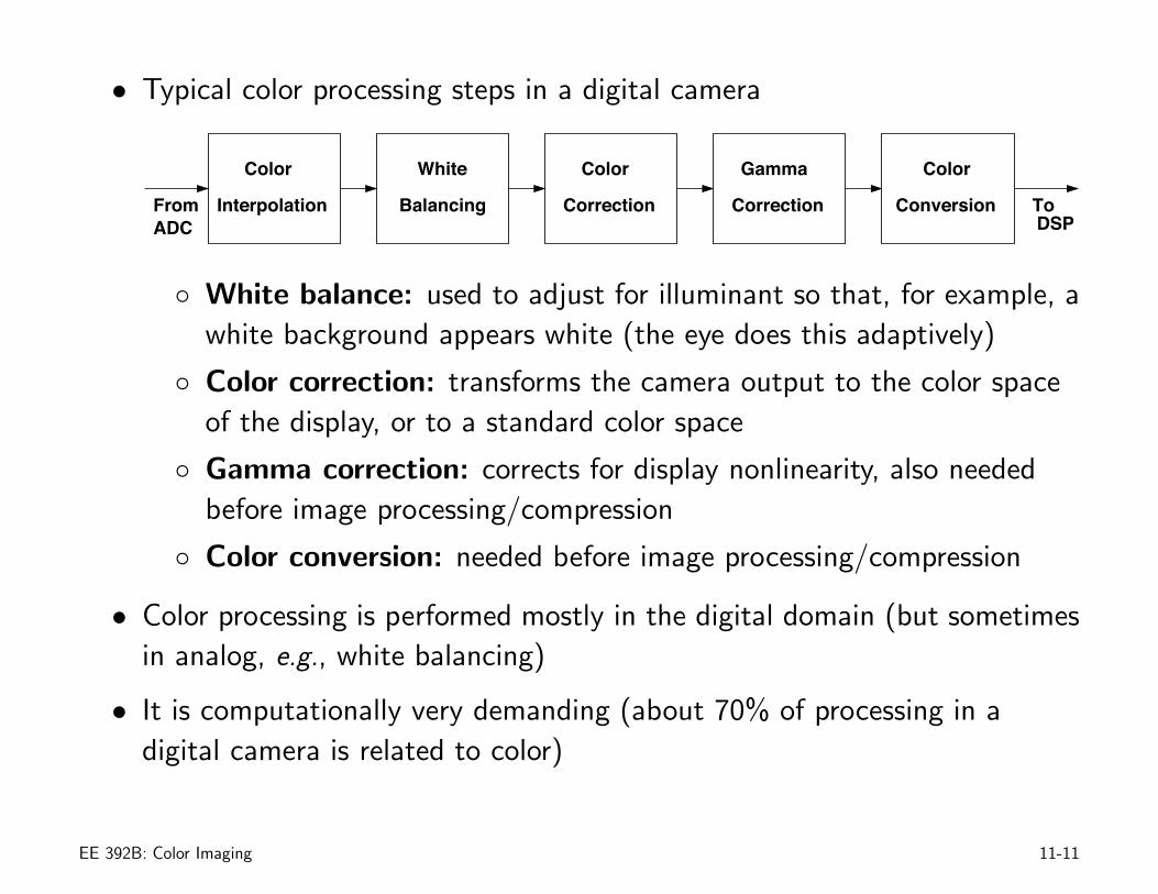
• Typical color processing steps in a digital camera
Color
Correction
White
Balancing
Color
InterpolationFromADC
Correction Conversion
ColorGamma
ToDSP
◦ White balance: used to adjust for illuminant so that, for example, awhite background appears white (the eye does this adaptively)
◦ Color correction: transforms the camera output to the color spaceof the display, or to a standard color space
◦ Gamma correction: corrects for display nonlinearity, also neededbefore image processing/compression
◦ Color conversion: needed before image processing/compression
• Color processing is performed mostly in the digital domain (but sometimesin analog, e.g., white balancing)
• It is computationally very demanding (about 70% of processing in adigital camera is related to color)
EE 392B: Color Imaging 11-11
Color Interpolation (Demozaicing)
• Used to reconstruct the missing pixel color components (when a CFA isused)
• Interpolation method must
◦ Reduce artifacts such as aliasing and color fringing (false colors)
◦ Have reasonable computational complexity
Interpolation algorithms:
• Nearest neighbor replication
◦ To reconstruct a missing color component of a pixel, simply set itequal to the value of its nearest pixel with that color
◦ Simple and fast, but results in large artifacts especially at edges
• Bilinear interpolation
◦ Perform bilinear interpolation in each color plane
EE 392B: Color Imaging 11-12
◦ relatively simple, but still suffers from some edge artifacts (may notbe visible in a video sequence)
• 2-D filtering
◦ This is a generalization of bilinear interpolation
◦ The filter window size and coefficients for each color plane aredesigned to reduce artifacts
◦ Artifacts will still exist around edges
• Adaptive algorithms
◦ Since most artifacts occur around edges, change (adapt) theinterpolation method when edges are present
◦ Yields better performance but requires more computations (for edgedetection)
EE 392B: Color Imaging 11-13
Interpolation Algorithms — Examples
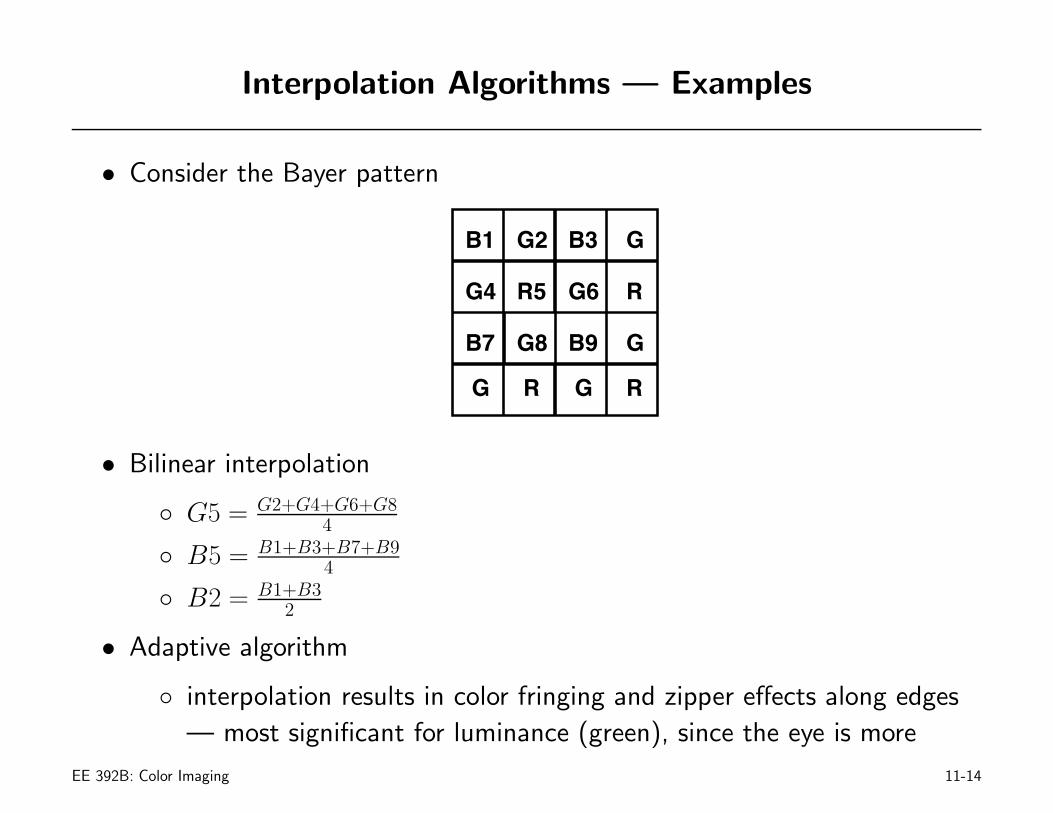
• Consider the Bayer pattern
B1 G2
G4 R5
B3
B7 G8 B9
R
R
G
G
G6
G R G
• Bilinear interpolation
◦ G5 = G2+G4+G6+G84
◦ B5 = B1+B3+B7+B94
◦ B2 = B1+B32
• Adaptive algorithm
◦ interpolation results in color fringing and zipper effects along edges— most significant for luminance (green), since the eye is more
EE 392B: Color Imaging 11-14
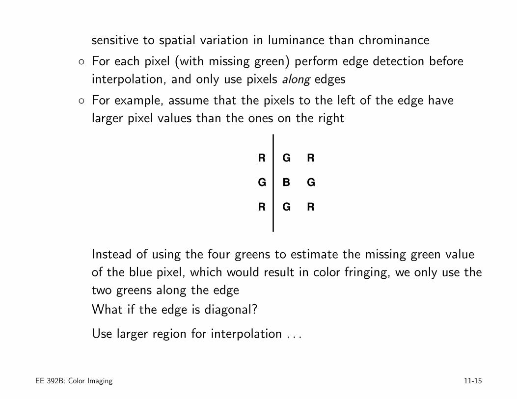
sensitive to spatial variation in luminance than chrominance
◦ For each pixel (with missing green) perform edge detection beforeinterpolation, and only use pixels along edges
◦ For example, assume that the pixels to the left of the edge havelarger pixel values than the ones on the right
R
G
R
G
B
G
R
G
R
Instead of using the four greens to estimate the missing green valueof the blue pixel, which would result in color fringing, we only use thetwo greens along the edge
What if the edge is diagonal?
Use larger region for interpolation . . .
EE 392B: Color Imaging 11-15
White Balancing
• Different light sources (illuminants) have different power spectral densities(psd)
• The psd of color reflected from an object is a function of both theobject’s surface reflectance and the illuminant psd
more specifically the photon flux density at a pixel is proportional to theproduct of the object surface reflectance S(λ) and the illuminant psdE(λ), i.e., f0(λ) ∝ E(λ)S(λ)
• So, for example, a raw image taken by a camera of a white piece of paperwill look yellowish under incandescent lighting and greenish underfluorescent lighting compared to under day light
• The eye, by comparison, would see the white paper as white almostindependent of the illuminant, and in a scene with white background itadjusts the colors in the scene so that the background looks white
• Captured images must also be processed so that a white backgroundlooks white — this is called white (color) balancing
EE 392B: Color Imaging 11-16
Two Approaches to White Balancing
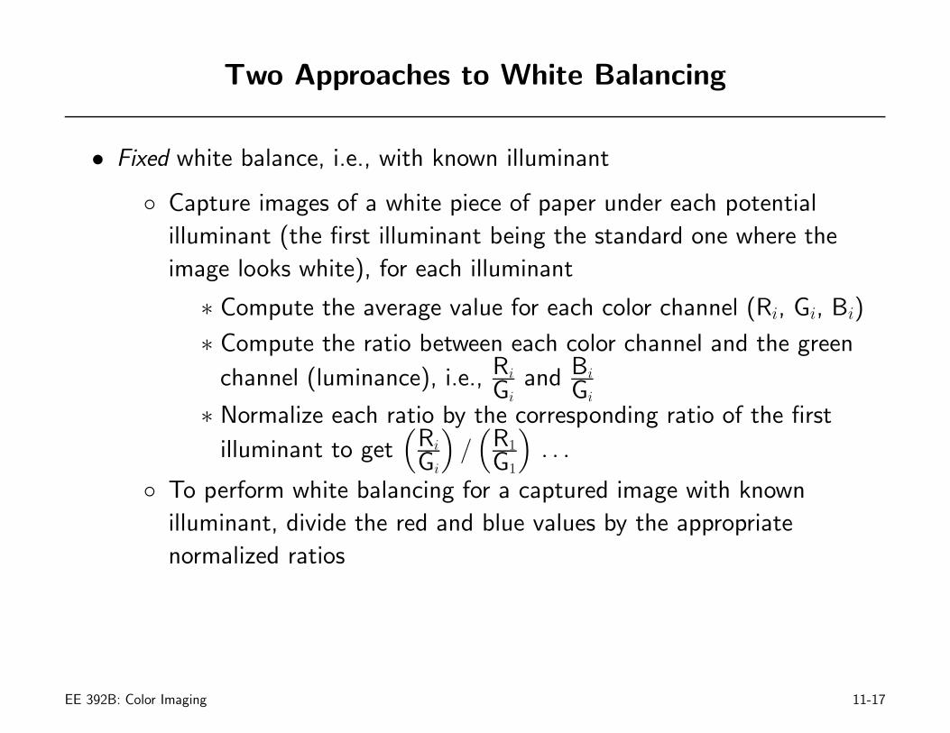
• Fixed white balance, i.e., with known illuminant
◦ Capture images of a white piece of paper under each potentialilluminant (the first illuminant being the standard one where theimage looks white), for each illuminant
∗ Compute the average value for each color channel (Ri, Gi, Bi)
∗ Compute the ratio between each color channel and the green
channel (luminance), i.e., Ri
Giand Bi
Gi
∗ Normalize each ratio by the corresponding ratio of the first
illuminant to get(
Ri
Gi
)/(
R1
G1
). . .
◦ To perform white balancing for a captured image with knownilluminant, divide the red and blue values by the appropriatenormalized ratios
EE 392B: Color Imaging 11-17
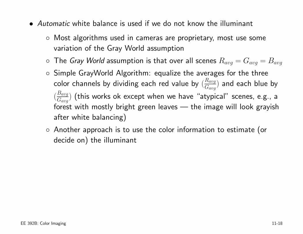
• Automatic white balance is used if we do not know the illuminant
◦ Most algorithms used in cameras are proprietary, most use somevariation of the Gray World assumption
◦ The Gray World assumption is that over all scenes Ravg = Gavg = Bavg
◦ Simple GrayWorld Algorithm: equalize the averages for the threecolor channels by dividing each red value by (Ravg
Gavg) and each blue by
(BavgGavg
) (this works ok except when we have “atypical” scenes, e.g., aforest with mostly bright green leaves — the image will look grayishafter white balancing)
◦ Another approach is to use the color information to estimate (ordecide on) the illuminant
EE 392B: Color Imaging 11-18
Color Correction
• Color filter technology and photodetector spectral response determine thecamera color space
• To ensure that color from the camera looks the same on a display, thecamera output must be transformed to the display color spectral responsespace
• Since there may be many display types used to render a captured image, itis customary to transform the camera output to a standard color space,e.g., corresponding to the LMS spectral responses, in the camera —correction for each display type is performed outside the camera
• To transform the camera output to a standard color space we use a 3 × 3matrix D, thus if C is the color from a pixel, the corrected color
Co = DC
EE 392B: Color Imaging 11-19
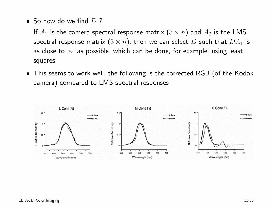
• So how do we find D ?
If A1 is the camera spectral response matrix (3 × n) and A2 is the LMSspectral response matrix (3 × n), then we can select D such that DA1 isas close to A2 as possible, which can be done, for example, using leastsquares
• This seems to work well, the following is the corrected RGB (of the Kodakcamera) compared to LMS spectral responses
EE 392B: Color Imaging 11-20
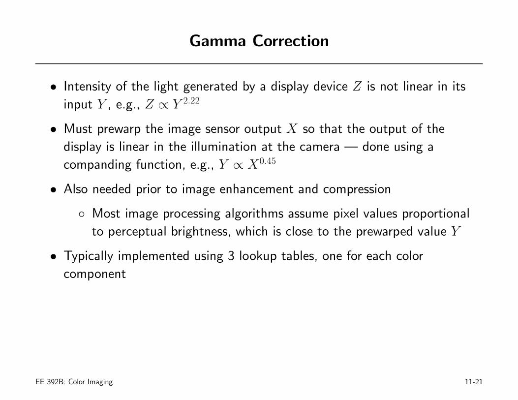
Gamma Correction
• Intensity of the light generated by a display device Z is not linear in itsinput Y , e.g., Z ∝ Y 2.22
• Must prewarp the image sensor output X so that the output of thedisplay is linear in the illumination at the camera — done using acompanding function, e.g., Y ∝ X0.45
• Also needed prior to image enhancement and compression
◦ Most image processing algorithms assume pixel values proportionalto perceptual brightness, which is close to the prewarped value Y
• Typically implemented using 3 lookup tables, one for each colorcomponent
EE 392B: Color Imaging 11-21
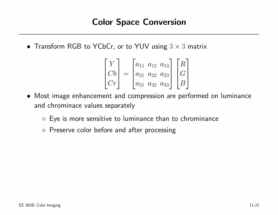
Color Space Conversion
• Transform RGB to YCbCr, or to YUV using 3 × 3 matrix
⎡
⎢⎣YCbCr
⎤
⎥⎦ =
⎡
⎢⎣a11 a12 a13
a21 a22 a23
a31 a32 a33
⎤
⎥⎦
⎡
⎢⎣RGB
⎤
⎥⎦
• Most image enhancement and compression are performed on luminanceand chrominace values separately
◦ Eye is more sensitive to luminance than to chrominance
◦ Preserve color before and after processing
EE 392B: Color Imaging 11-22