MLA-00012N art NEW - · PDF fileRed 120 Ω To Next MLA Gage Back Light A (V in) B...
2
Installation Instructions for MurphyLink TM Analog Gages Series: MLA20 and MLA35 MLA-00012N Revised 10-04 Section 78 00-02-0424 Description The MurphyLink TM gages are a series of instruments designed to display the information transmitted by the Murphy Display and Diagnostic Module (MDDM) in a traditional analog format. Communication from the MDDM to these units is via an RS485 twisted pair proprietary serial link. These MurphyLink TM components are environmentally sealed, LED back lit (green) and are available in a standard 2 in. (51 mm) diameter, plastic case. The MLA35 Series models feature a 3-3/8 in. (86 mm) diameter, plastic case. Specifications Power Supply: Input Voltage: 12V (10-16 VDC min. & max. voltage). 24V (18-32 VDC min. & max. voltage). Operating Current: (@ 14 VDC) = MLA20: 27 mA min.; 50 mA max. MLA35: 43 mA min.; 48 mA max. Backlight: Voltage: 12 to 14 VDC (See NOTE below). Maximum Current: 30 mA. Input: RS485 data (MurphyLink TM proprietary protocol). Output: Analog Readout. Operating Temperature: -40° to 185°F (-40° to 85°C). Storage Temperature: -76° to 185°F (-60° to 85°C). Dial: White numerals over black background: MLA20: 90° sweep; MLA35: 250° sweep. Gage Accuracy: MLA20: Better than ±1.5% of scale. MLA35: Better than ±2% of scale. Enclosure: Environmentally Sealed. Material: Case and Clamp: Polyester (PBT). Lens: Polycarbonate. Bezel: Stainless Steel (Black optional). Please read the following information before installing. A visual inspection of this product for damage during ship- ping is recommended before mounting. It is your responsibility to have a qualified person install this unit. GENERAL INFORMATION Basic 2 in. (51 mm) case models MLA20-A-100-A Engine Oil Pressure MLA20-B-250-A Coolant Temperature MLA20-C-12-A Voltmeter 12 VDC MLA20-C-24-A Voltmeter 24 VDC MLA20-D-100-A Percent Load @ Current Speed MLA20-E-400-A Gear Oil Pressure MLA20-F-250-A Gear Oil Temperature Basic 3-3/8 in. (86 mm) case models MLA35-T-3000-A Tachometer MLA35-S-85-A Speedometer NOTE: All basic models listed above are available with Amp mini universal (standard), Deutsch or Metri-Pack connectors. CAUTION: These instruments are designed to be used ONLY with the MurphyLink TM Display and Diagnostic module (MDDM) or other approved MurphyLink TM products. NOTE: MLVC2412 Regulator required for 24 VDC Systems. WARNING BEFORE BEGINNING INSTALLATION OF THIS MURPHY PRODUCT ✔ Disconnect all electrical power to the machine. ✔ Make sure the machine cannot operate during installation. ✔ Follow all safety warnings of the machine manufacturer. ✔ Read and follow all installation instructions. MLA20 Series MLA35 Series Warranty A limited warranty on materials and workmanship is given with this FWMurphy product. A copy of the warranty may be viewed or printed by going to www.fwmurphy.com/warranty.asp . In order to consistently bring you the highest quality, full featured products, we reserve the right to change our specifications and designs at any time. Installation MLA-00012N page 1 of 2
Transcript of MLA-00012N art NEW - · PDF fileRed 120 Ω To Next MLA Gage Back Light A (V in) B...
Installation Instructions for MurphyLinkTM
Analog Gages Series: MLA20 and MLA35
MLA-00012NRevised 10-04
Section 7800-02-0424
DescriptionThe MurphyLinkTM gages are a series of instruments designed to display theinformation transmitted by the Murphy Display and Diagnostic Module(MDDM) in a traditional analog format. Communication from the MDDM tothese units is via an RS485 twisted pair proprietary serial link. TheseMurphyLinkTM components are environmentally sealed, LED back lit (green)and are available in a standard 2 in. (51 mm) diameter, plastic case. TheMLA35 Series models feature a 3-3/8 in. (86 mm) diameter, plastic case.
SpecificationsPower Supply:
Input Voltage: 12V (10-16 VDC min. & max. voltage).24V (18-32 VDC min. & max. voltage).
Operating Current: (@ 14 VDC) = MLA20: 27 mA min.; 50 mA max.MLA35: 43 mA min.; 48 mA max.
Backlight:Voltage: 12 to 14 VDC (See NOTE below).Maximum Current: 30 mA.
Input: RS485 data (MurphyLinkTM proprietary protocol).Output: Analog Readout. Operating Temperature: -40° to 185°F (-40° to 85°C).Storage Temperature: -76° to 185°F (-60° to 85°C).Dial: White numerals over black background:
MLA20: 90° sweep; MLA35: 250° sweep.Gage Accuracy: MLA20: Better than ±1.5% of scale.
MLA35: Better than ±2% of scale.Enclosure: Environmentally Sealed.Material:
Case and Clamp: Polyester (PBT).Lens: Polycarbonate.Bezel: Stainless Steel (Black optional).
Please read the following information before installing. A visual inspection of this product for damage during ship-ping is recommended before mounting. It is your responsibility to have a qualified person install this unit.
GENERAL INFORMATION
Basic 2 in. (51 mm) case models MLA20-A-100-A Engine Oil Pressure
MLA20-B-250-A Coolant Temperature
MLA20-C-12-A Voltmeter 12 VDC
MLA20-C-24-A Voltmeter 24 VDC
MLA20-D-100-A Percent Load @ Current Speed
MLA20-E-400-A Gear Oil Pressure
MLA20-F-250-A Gear Oil Temperature
Basic 3-3/8 in. (86 mm) case modelsMLA35-T-3000-A Tachometer
MLA35-S-85-A Speedometer
NOTE: All basic models listed above are available with Amp mini universal (standard), Deutsch or Metri-Pack connectors.
CAUTION: These instruments are designed to be used ONLYwith the MurphyLinkTM Display and Diagnostic module (MDDM)or other approved MurphyLinkTM products.
NOTE: MLVC2412 Regulator required for 24 VDC Systems.
WARNINGBEFORE BEGINNING INSTALLATION OF THIS MURPHY PRODUCT
Disconnect all electrical power to the machine.
Make sure the machine cannot operate during installation.
Follow all safety warnings of the machine manufacturer.
Read and follow all installation instructions.
MLA20 Series MLA35 Series
WarrantyA limited warranty on materials and workmanship is given with thisFWMurphy product. A copy of the warranty may be viewed or printed bygoing to www.fwmurphy.com/warranty.asp.
In order to consistently bring you the highest quality, full featured products, we reserve the right to change our specifications and designs at any time.
Installation MLA-00012N page 1 of 2
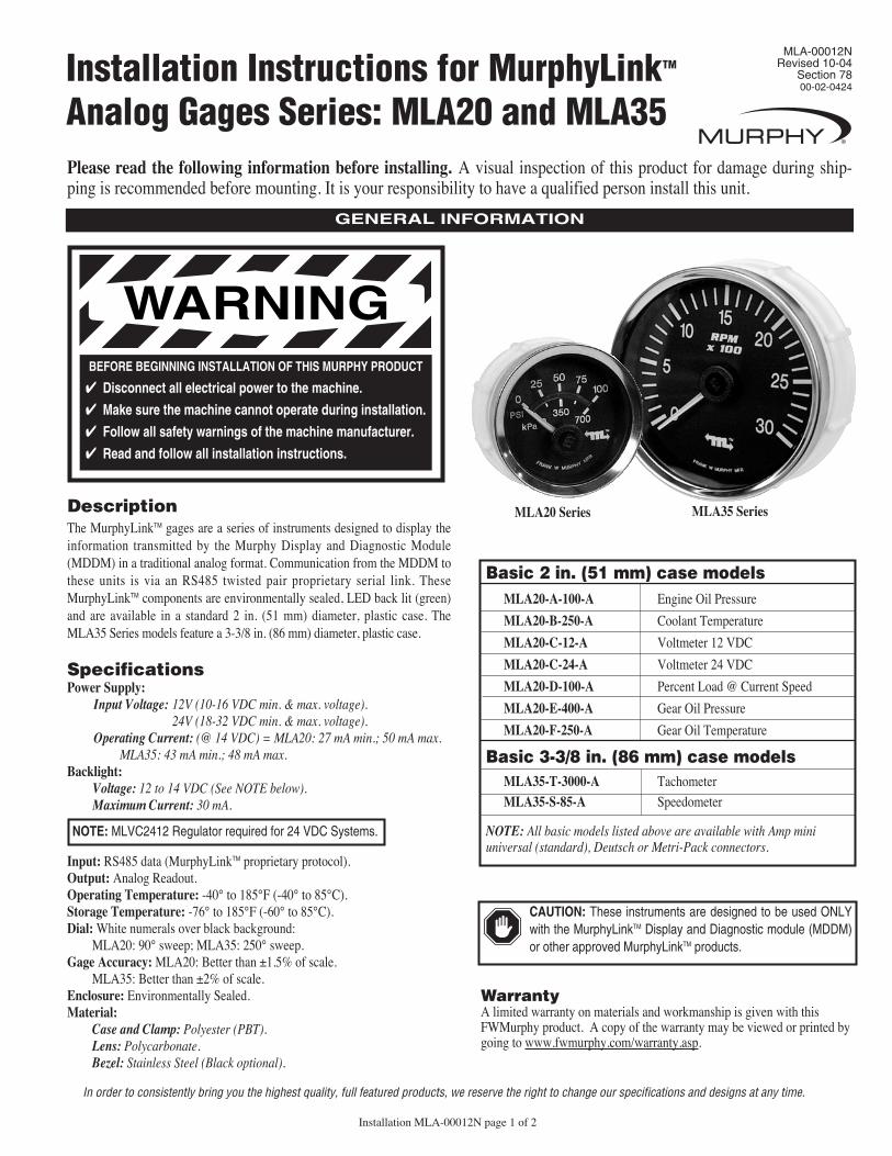
MLA20 and MLA35 Dimensions and Mounting
For Panels up to 3/4 in. (19 mm)maximum thickness
For Panels up to 3/8 in.(9.5 mm) maximum thickness
Mounting Clamp
Mounting Hole2.062 in. (52 mm) Dia.
2.25 in. (57 mm) 1.94 in. (49 mm)
0.48 in. (12 mm) Push On Plug (Amp)Connection
1.94 in.(49 mm)
Mounting Clamp
Mounting Hole3.375 in. (86 mm) Dia.
3.55 in. (90 mm) 2.0 in. (51 mm)
0.48 in. (12 mm)
3.22 in.(82 mm)
Push On Plug (Amp)Connection
For Panels up to 3/4 in. (19 mm)maximum thickness
For Panels up to 3/8 in. (9.5 mm) maximum thickness
MLA20 Series MLA35 Series
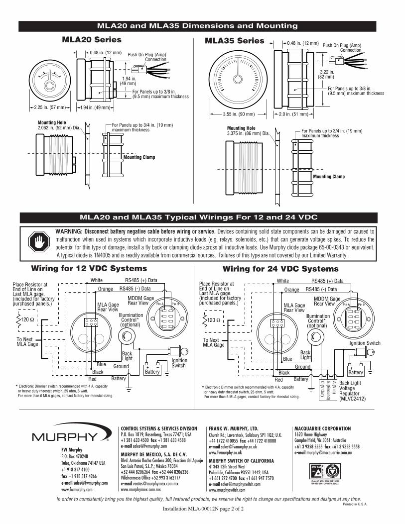
Orange
Battery
IgnitionSwitch
Red
120 Ω
Place Resistor atEnd of Line onLast MLA gage.(included for factorypurchased panels.)
To Next MLA Gage
BackLight
Ground
Battery
Blue
White RS485 (+) Data
RS485 (-) Data
MDDM GageRear View
IlluminationControl*(optional)
* Electronic Dimmer switch recommended with 4 A, capacity or heavy duty rheostat switch, 25 ohm, 5 watt. For more than 6 MLA gages, contact factory for rheostat sizing.
MLA GageRear View
Pin A Pin H
Black
Orange
Battery
Ignition Switch
Red
120 Ω
To Next MLA Gage
BackLight
Ground
A (V in)B (Ground)C (V Out)
Battery
Blue
White RS485 (+) Data
RS485 (-) Data
MDDM GageRear View
IlluminationControl*(optional)
Back LightVoltage Regulator(MLVC2412)
* Electronic Dimmer switch recommended with 4 A, capacity or heavy duty rheostat switch, 25 ohm, 5 watt. For more than 6 MLA gages, contact factory for rheostat sizing.
MLA GageRear View
Pin A Pin H
Black
Place Resistor atEnd of Line onLast MLA gage.(included for factorypurchased panels.)
Wiring for 12 VDC Systems Wiring for 24 VDC Systems
WARNING: Disconnect battery negative cable before wiring or service. Devices containing solid state components can be damaged or caused tomalfunction when used in systems which incorporate inductive loads (e.g. relays, solenoids, etc.) that can generate voltage spikes. To reduce thepotential for this type of damage, install a fly back or clamping diode across all inductive loads. Use Murphy diode package 65-00-0343 or equivalent.A typical diode is 1N4005 and is readily available from commercial sources. Failures of this type are not covered by our Limited Warranty.
MLA20 and MLA35 Typical Wirings For 12 and 24 VDC
Installation MLA-00012N page 2 of 2
CONTROL SYSTEMS & SERVICES DIVISIONP.O. Box 1819; Rosenberg, Texas 77471; USA+1 281 633 4500 fax +1 281 633 4588 e-mail [email protected]
MURPHY DE MEXICO, S.A. DE C.V.Blvd. Antonio Rocha Cordero 300, Fracción del Aguaje San Luis Potosí, S.L.P.; México 78384 +52 444 8206264 fax +52 444 8206336Villahermosa Office +52 993 3162117e-mail [email protected]
FRANK W. MURPHY, LTD.Church Rd.; Laverstock, Salisbury SP1 1QZ; U.K.+44 1722 410055 fax +44 1722 410088 e-mail [email protected]
MURPHY SWITCH OF CALIFORNIA41343 12th Street WestPalmdale, California 93551-1442; USA+1 661 272 4700 fax +1 661 947 7570e-mail [email protected]
In order to consistently bring you the highest quality, full featured products, we reserve the right to change our specifications and designs at any time.
MACQUARRIE CORPORATION1620 Hume HighwayCampbellfield, Vic 3061; Australia +61 3 9358 5555 fax +61 3 9358 5558e-mail [email protected] FW Murphy
P.O. Box 470248Tulsa, Oklahoma 74147 USA +1 918 317 4100 fax +1 918 317 4266 e-mail [email protected] www.fwmurphy.com
REGISTERED
USA–ISO 9001:2000 FM 28221UK–ISO 9001:2000 FM 29422
Printed in U.S.A.


![Model MB MAGNETIC BASE - kanetec.co.jp · Mounted on a magnetic base or High Lock Base to secure a dial gage, linear gage, etc. [Features] φ6 shaft to suit the mounting hole of MB](https://static.fdocument.org/doc/165x107/5d6448a088c993011a8badef/model-mb-magnetic-base-mounted-on-a-magnetic-base-or-high-lock-base-to-secure.jpg)