


γλώσσες
Σελίδες
Νομικός

5450/5451Ultra High Resistance Meter
http://www.adcmt-e.com
BCDFactory option
Active in chemical and material fields Suitable for semiconductor evaluation
l High resolution of 5½-digit display
l Micro current measurement: 1fA to 19.9999mA
l High-resistance measurement: 3 x 10¹⁷Ω (current function)
l Voltage source: ±1mV to ±1000V
l High-speed measurement: up to 1000 readings/sec
l Floating measurement of 1000V (5450)
l Temperature and humidity measurement (with the optional accessory)
l Preset function for easy measurement condition setting
l Sequence program for routine measurement
Ultra High Resistance Measurement Leak Current Measurement High-Speed Measurement
Maximum Resolution Readings/sec
3×10¹⁷Ω 1 fA 1000
The new standard of Ultra-High Resistance/Current Meter2
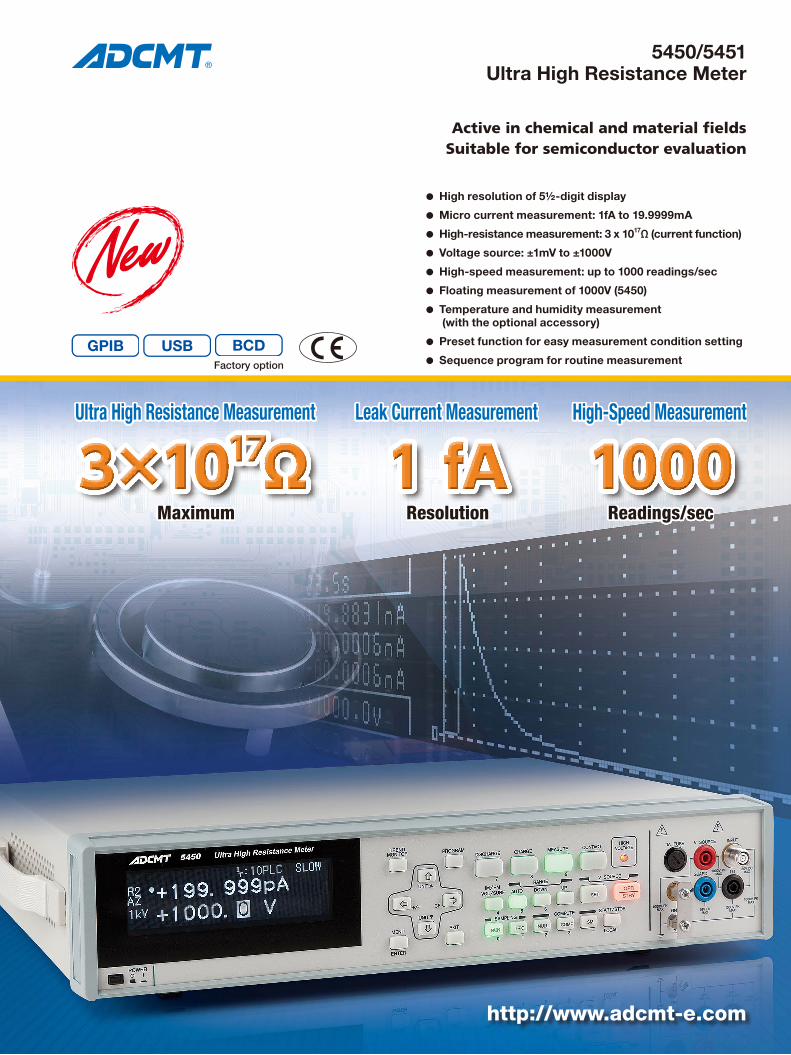
The 5450/5451 is a state-of-the-art ultra high resistance meter with 5½-digit display that integrates ADC’s tradi-tional technologies and new DC amplifier technologies. It was designed for ease of use so that anybody who operates this instrument can get the same measure-ment results. The 5450/5451 will be the new standard for insulation resistance measurement or micro current measurement of various kinds of insulating materials or semiconductors.
High Performance/High SpeedThe 5450/5451 is ten times or more high performance than the conventional models. For example, the cur-rent measurement resolution is 1 fA, the high resistance measurement range is 3 x 10¹⁷Ω, the voltage to be ap-plied to DUTs is up to ±1000V, the measurement speed is 1000 readings per second and the memory capacity for measurement results is 65000 data.In addition, temperature and humidity can be measured at the same time with insulation resistance by using the optional accessory.
Easy to UseThe 5450/5451 is equipped with the preset function to set measurement conditions separately for each target device, the sequence program to always perform the same mea-surement, and the graphical display function to measure visually transient current of capacitive DUTs.
Automatic SystemThe 5450/5451 adopts the GPIB and the USB as stan-dard interface and the BCD output optionally. In ad-dition, the handler interface and the analog output are available to synchronize with other automatic devices.
Such a high-performance instrument, 5450/5451 is used in testing of secondary cell and semiconductor materi-als or testing of electronic parts such as capacitors and print-circuited boards. In addition, it can be used in various usages for insulating materials such as synthetic resins and rubbers from R&D, manufacturing to quality inspection fields.Especially in testing of insulating materials, surface resistivity and volume resistivity measurement conform-ing to JIS (Japanese Industrial Standards) are available by using the various types of fixtures in combination.For micro current measurement, leak current of a semi-conductor device at high-voltage application can be measured with high sensitivity and at high speed.The 5451 is provided with floating measurement capa-bility up to 46 V peak. However, to test securely a DUT that is grounded at one side, the 5450 that is capable of floating measurement up to 1000 V peak is the best.
New Standard of Insulation Resistance and Micro Current Measurement
Flexible High PerformanceMeasurement 3×10¹⁷Ω and 1fA, Voltage Source ±1000V
The new standard of Ultra-High Resistance/Current Meter
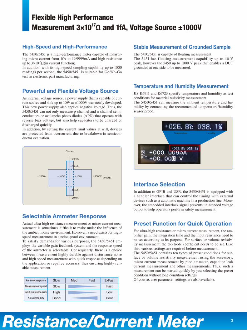
-1000V +1000V Voltage
Current
+20mA
+10mA
-10mA
+100V-100V
-20mA
3
Powerful and Flexible Voltage Source
Selectable Ammeter Response
High-Speed and High-Performance Stable Measurement of Grounded Sample
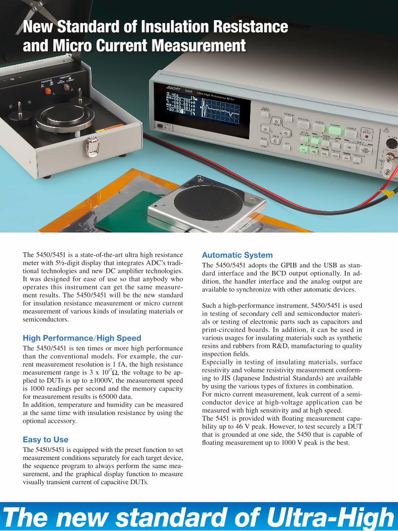
Temperature and Humidity Measurement
Interface Selection
Preset Function for Quick Operation
As internal voltage source, a power supply that is capable of cur-rent source and sink up to 10W at ±1000V was newly developed. This new power supply also applies negative voltage. Thus, the 5450/5451 can not only measure p-channel and n-channel semi-conductors or avalanche photo diodes (APD) that operate with reverse bias voltage, but also help capacitors to be charged or discharged quickly.In addition, by setting the current limit values at will, devices are protected from overcurrent due to breakdown in semicon-ductor evaluation.
Actual ultra-high resistance measurement or micro current mea-surement is sometimes difficult to make under the influence of the ambient noise environment. However, a need exists for high-speed measurement in a noise-proof environment.To satisfy demands for various purposes, the 5450/5451 em-ploys the variable gain feedback system and the response speed of the ammeter is selectable. Consequently, there is a choice between measurement highly durable against disturbance noise and high-speed measurement with quick response depending on the application or required accuracy, thus ensuring highly reli-able measurement.
The 5450/5451 is a high-performance meter capable of measur-ing micro current from 1fA to 19.9999mA and high resistance up to 3×10¹⁷Ω(in current function).In addition, with its high-speed sampling capability up to 1000 readings per second, the 5450/5451 is suitable for Go/No-Go test in electronic part manufacturing.
The 5450/5451 is capable of floating measurement.The 5451 has floating measurement capability up to 46 V peak, however the 5450 up to 1000 V peak that enables a DUT grounded at one side to be measured.
JIS K6911 and K6723 specify temperature and humidity as test conditions for material resistivity measurement.The 5450/5451 can measure the ambient temperature and hu-midity by connecting the recommended temperature/humidity sensor probe.
In addition to GPIB and USB, the 5450/5451 is equipped with a handler interface that can control the timing with external devices such as a automatic machine in a production line. More-over, the embedded interlock signal prevents unintended voltage output to help operators perform safety measurement.
For ultra-high resistance or micro current measurement, the am-plifier gain, the integration time and the input resistance need to be set according to its purpose. For surface or volume resistiv-ity measurement, the electrode coefficient needs to be set. Like this, various settings are required before measurement.The 5450/5451 contains ten types of preset conditions for sur-face or volume resistivity measurement using the accessory, micro current measurement by pico ammeter, capacitor leak current measurement and other measurements. Thus, such a measurement can be started quickly by just selecting the preset condition without long condition settings.Of course, user parameter settings are also available.Ammeter response Slow Med Fast ExFast
Measurement speed Slow Fast
Input resistance error High Low
Noise immunity Good Poor
Temperature Humidity
Graphic Display, Contact Check Function and Other Various FunctionsAssures Consistent Measurement Results
The new standard of Ultra-High Resistance/Current Meter
Driving guard
Normal connector 5450 connector
Input terminal Driving guard terminal covered with insulating material
Driving guard
Input terminal
Grounded sample
Reverse-polarity voltage
Voltage source:0V to ±1000V
5450
+-
Start
Voltage
Discharge time Discharge timeCharge time
Measurement display
Measurement (No display)
Discharge DischargeCharge
Charge
Measurement Stop
4
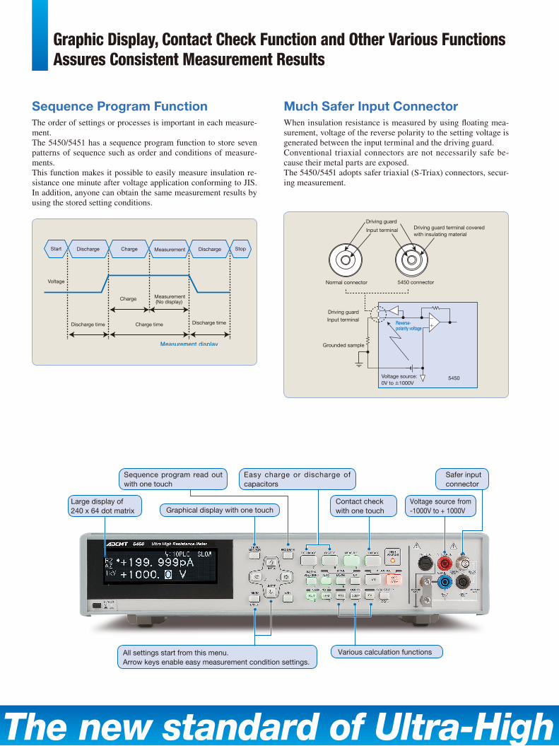
Much Safer Input ConnectorSequence Program FunctionWhen insulation resistance is measured by using floating mea-surement, voltage of the reverse polarity to the setting voltage is generated between the input terminal and the driving guard.Conventional triaxial connectors are not necessarily safe be-cause their metal parts are exposed.The 5450/5451 adopts safer triaxial (S-Triax) connectors, secur-ing measurement.
The order of settings or processes is important in each measure-ment.The 5450/5451 has a sequence program function to store seven patterns of sequence such as order and conditions of measure-ments.This function makes it possible to easily measure insulation re-sistance one minute after voltage application conforming to JIS. In addition, anyone can obtain the same measurement results by using the stored setting conditions.
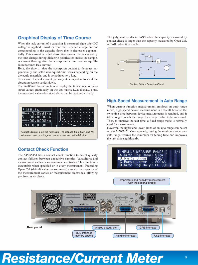
Contact checkwith one touch
Voltage source from -1000V to + 1000V
Safer inputconnector
Large display of 240 x 64 dot matrix Graphical display with one touch
Sequence program read out with one touch
All settings start from this menu.Arrow keys enable easy measurement condition settings.
Various calculation functions
Easy charge or discharge of capacitors
The new standard of Ultra-High Resistance/Current Meter
Rear panel
5
Graphical Display of Time Course
Contact Check Function
High-Speed Measurement in Auto Range
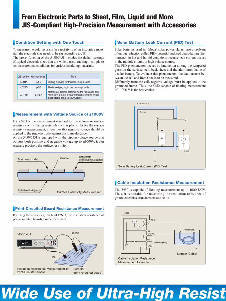
When the leak current of a capacitor is measured, right after DC voltage is applied, inrush current that is called charge current corresponding to the capacity flows then it decreases exponen-tially. This current is called absorption current that is caused by the time change during dielectric polarization inside the sample. A current flowing after the absorption current reaches equilib-rium becomes leak current.Here, the time it takes the absorption current to decrease ex-ponentially and settle into equilibrium varies depending on the dielectric materials, and is sometimes very long.To measure the leak current precisely, it is important to see if the abruption current settles down.The 5450/5451 has a function to display the time course of mea-sured values graphically on the dot-matrix LCD display. Thus, the measured values described above can be captured visually.
The 5450/5451 has a contact check function to detect quickly contact failures between capacitive samples (capacitors) and measurement cables or measurement electrodes. This function is executable when specified or in every measurement. Preceding Open Cal (default value measurement) cancels the capacity of the measurement cables or measurement electrodes, allowing precise contact check.
The judgment results in PASS when the capacity measured by contact check is larger than the capacity measured by Open Cal, or FAIL when it is smaller.
When current function measurement employs an auto range mode, high-speed device measurement is difficult because the switching time between device measurements is required, and it takes long to reach the range for a target value to be measured. Thus, to improve the takt time, a fixed range mode is normally used for measurement.However, the upper and lower limits of an auto range can be set on the 5450/5451. Consequently, setting the minimum necessary auto range realizes the minimum switching time and improves the takt time significantly.
A
Vac
INPUT
Cx
VsHi
Lo
Temperature and humidity measurement (with the optional probe)
BCD interface (factory option)
Analog output, etc.
Handler interface
GPIB interface
USB interface
A graph display is on the right side. The elapsed time, MAX and MIN values and source voltage of measurement are on the left side.
Contact Failure Detection Circuit
From Electronic Parts to Sheet, Film, Liquid and MoreJIS-Compliant High-Precision Measurement with Accessories
Wide Use of Ultra-High Resistance/Current Meter
Water tank
(Shorting bar)
Lo
INPUT
5450
GND
Vs
GUARD
A
6
Solar Battery Leak Current (PID) Test Condition Setting with One Touch
Measurement with Voltage Source of ±1000V
Print-Circuited Board Resistance Measurement
Cable Insulation Resistance Measurement
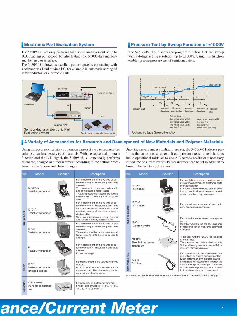
Solar batteries used in “Mega” solar power plants have a problem of output reduction called PID (potential-induced degradation) phe-nomenon in hot and humid conditions because leak current occurs in the module circuits at high voltage source. The PID phenomenon occurs by interaction among the tempered glass on the surface, cell, back sheet and the aluminum frame of a solar battery. To evaluate this phenomenon, the leak current be-tween the cell and frame needs to be measured.Differently from the cell, negative voltage must be applied to the grounded frame. Thus, the 5450 capable of floating measurement of - 1000 V is the best choice.
To measure the volume or surface resistivity of an insulating mate-rial, the electrode size needs to be set according to JIS.The preset function of the 5450/5451 includes the default settings of typical electrode sizes that are widely used, making it simple to set measurement conditions for various insulating materials.
JIS K6911 is the measurement standard for the volume or surface resistivity of insulating materials such as plastic. As for the surface resistivity measurement, it specifies that negative voltage should be applied to the ring electrode against the main electrode.As the 5450/5451 is equipped with the bipolar voltage source that outputs both positive and negative voltage up to ±1000V, it can measure precisely the surface resistivity.
By using the accessory, test lead 12603, the insulation resistance of print-circuited boards can be measured.
The 5450 is capable of floating measurement up to 1000 DCV. Thus, it is suitable for measuring the insulation resistance of grounded cables, transformers and so on.
JIS number Electrode size Title
K6911 φ50 Testing methods for thermosetting plastics
K6723 φ70 Plasticized polyvinyl chloride compounds
C2170 φ30.5Methods of test for determining the resistance and resistivity of solid planar materials used to avoid electrostatic charge accumulation
Solar Battery
Frame
Cell
R A
5450
Backside electrode (guard)
Main electrode
Sample (print-circuited board)
Sample (Cable)
Sample
Insulation Resistance Measurement of Print-Circuited Board
Cable Insulation Resistance Measurement Example
Solar Battery Leak Current (PID) Test
5450/5451 12603
Vs
Ring electrode (Negative voltage application)
Surface Resistivity Measurement
Wide Use of Ultra-High Resistance/Current Meter
Purpose Model Exterior Description
Sheet o
r film
12702A/BResistivity chamber
For measurement of the volume or sur-face resistivity of sheet, filmy and platy samples.The pressure to a sample is adjustable and its thickness is measureable.Thus, it is possible to measure the sample with the electrode firmly fixed by pres-sure.
12704AResistivity chamber
For measurement of the volume or sur-face resistivity of sheet, filmy and platy samples. Adhesion with a sample is excellent because all electrodes use con-ductive rubber.One-touch switching between volume and surface resistivity measurement.
12708Resistivity chamber
For measurement of the volume or sur-face resistivity of sheet, filmy and platy samples. Temperature in the range from normal temperature to +200°C can be applied to a sample.
42Resistivity chamber
For measurement of the volume or sur-face resistivity of sheet, filmy and platy samples. For normal usage
Liquid
12707Resistivity chamber for liquid sample
For measurement of the volume resistivity of liquid.It requires only 0.8cc of sample for measurement. The electrodes can be removed and cleaned easily.
Inspectio
n
15045 seriesStandard resistance box
For inspection of digital electrometers.Five models available: 1×10⁸Ω, 1×10⁹Ω, 1×10¹⁰Ω, 1×10¹¹Ω, 1×10¹²Ω
Purpose Model Exterior Description
Electro
nic parts
12706ATest fixture
For insulation measurement or micro current measurement of electronic parts such as capacitor.Its structure takes shielding and isolation into account to allow stable measurement of low current and high resistance.
12701ATest fixture
For current measurement of electronic parts such as semiconductor.
12604Tweezers probe
For insulation measurement of chip ca-pacitors.With the tweezers-like shape, small chip components can be measured easily and efficiently.
A08076Shielded measure-ment plate
To be used with the 12604. For removing external noise.This measurement plate is shielded with Teflon, allowing measurement with low influence of induction noise.
Print-circuited board
12603Test lead
For insulation resistance measurement and voltage or current measurement be-tween patterns on print-circuited boards.It is suitable for measurement in which the measurement point is changed in succes-sion. An external power supply is required for insulation resistance measurement.
Program stop
Program start
Start voltage
Measuredvalue display
Measuredvalue display
Measuredvalue display
Measuredvalue display
Th Td
Tp Tp Tp
TdTd
Tp
Td
Step voltageStop voltage
For cables to connect the 5450/5451 with these accessories, refer to “Connection Cable List” on page 11.
7
Electronic Part Evaluation System
A Variety of Accessories for Research and Development of New Materials and Polymer Materials
Pressure Test by Sweep Function of ±1000V
The 5450/5451 not only performs high-speed measurement of up to 1000 readings per second, but also features the 65,000 data memory and the handler interface.The 5450/5451 shows its excellent performance by connecting with a scanner or a handler via a PC, for example in automatic sorting of semiconductors or electronic parts.
Using the accessory resistivity chambers makes it easy to measure the volume or surface resistivity of materials. With the sequential program function and the LID signal, the 5450/5451 automatically performs discharge, charged and measurement according to the setting proce-dure in cover’s open and close timings.
Once the measurement conditions are set, the 5450/5451 always per-forms the same measurement. It can prevent measurement failures due to operational mistakes to occur. Electrode coefficients necessary for volume or surface resistivity measurement can be set in addition to those of the resistivity chambers.
The 5450/5451 has a sequence program function that can sweep with a 4-digit setting resolution up to ±1000V. Using this function enables precise pressure test of semiconductors.
Semiconductor or Electronic Part Evaluation System Output Voltage Sweep Function
Setting items:Start voltage value (Vstart)Stop voltage value (Vstop)Step voltage value (Vstep)Step time (Tp)
Measurement delay time (Td)Hold time (Td)Reverse ON/OFFRepeat count (0 to 1000)
Controller
DUT
5450/5451
Handler interface
Semiconductors or electronic parts
INPUT
Vs
Scanner 7210
8
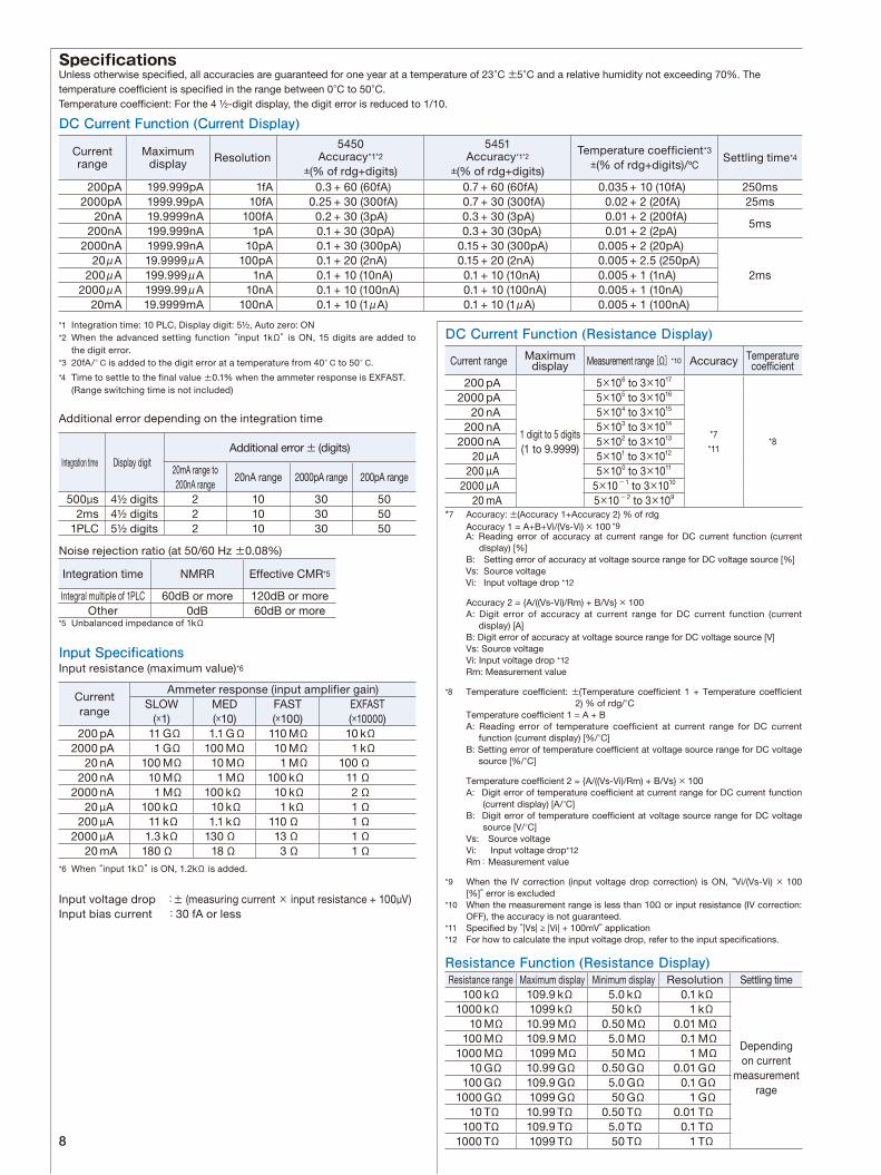
Specifications
DC Current Function (Current Display)
*1 Integration time: 10 PLC, Display digit: 5½, Auto zero: ON*2 When the advanced setting function “input 1kΩ” is ON, 15 digits are added to
the digit error.*3 20fA/°C is added to the digit error at a temperature from 40°C to 50°C.
*4 Time to settle to the final value ±0.1% when the ammeter response is EXFAST. (Range switching time is not included)
Additional error depending on the integration time
Noise rejection ratio (at 50/60 Hz ±0.08%)
*5 Unbalanced impedance of 1kΩ
Input SpecificationsInput resistance (maximum value)*6
*6 When “input 1kΩ” is ON, 1.2kΩ is added.
Input voltage drop :± (measuring current × input resistance + 100µV)Input bias current :30 fA or less
Unless otherwise specified, all accuracies are guaranteed for one year at a temperature of 23°C ±5°C and a relative humidity not exceeding 70%. The temperature coefficient is specified in the range between 0°C to 50°C.Temperature coefficient: For the 4 ½-digit display, the digit error is reduced to 1/10.
DC Current Function (Resistance Display)
*7 Accuracy: ±(Accuracy 1+Accuracy 2) % of rdg Accuracy 1 = A+B+Vi/(Vs-Vi) × 100 *9
A: Reading error of accuracy at current range for DC current function (current display) [%]
B: Setting error of accuracy at voltage source range for DC voltage source [%] Vs: Source voltage Vi: Input voltage drop *12
Accuracy 2 = A/((Vs-Vi)/Rm) + B/Vs × 100 A: Digit error of accuracy at current range for DC current function (current
display) [A] B: Digit error of accuracy at voltage source range for DC voltage source [V]
Vs: Source voltage Vi: Input voltage drop *12 Rm: Measurement value
*8 Temperature coefficient: ±(Temperature coefficient 1 + Temperature coefficient 2) % of rdg/°C
Temperature coefficient 1 = A + B A: Reading error of temperature coefficient at current range for DC current
function (current display) [%/°C] B: Setting error of temperature coefficient at voltage source range for DC voltage
source [%/°C]
Temperature coefficient 2 = A/((Vs-Vi)/Rm) + B/Vs × 100 A: Digit error of temperature coefficient at current range for DC current function
(current display) [A/°C] B: Digit error of temperature coefficient at voltage source range for DC voltage
source [V/°C] Vs: Source voltage Vi: Input voltage drop*12 Rm: Measurement value
*9 When the IV correction (input voltage drop correction) is ON, “Vi/(Vs-Vi) × 100 [%]” error is excluded
*10 When the measurement range is less than 10Ω or input resistance (IV correction: OFF), the accuracy is not guaranteed.
*11 Specified by “|Vs| ≥ |Vi| + 100mV” application*12 For how to calculate the input voltage drop, refer to the input specifications.
Resistance Function (Resistance Display)
Current range Maximum display Measurement range [Ω]*10 Accuracy Temperature
coefficient 200 pA
1 digit to 5 digits(1 to 9.9999)
5×10⁶ to 3×1017
*7
*11*8
2000 pA 5×10⁵ to 3×10¹⁶
20 nA 5×10⁴ to 3×10¹⁵
200 nA 5×10³ to 3×10¹⁴
2000 nA 5×10² to 3×10¹³
20 µA 5×101 to 3×10¹²
200 µA 5×100 to 3×10¹¹
2000 µA 5×10⁻¹ to 3×10¹⁰
20 mA 5×10- 2 to 3×10⁹
Resistance range Maximum display Minimum display Resolution Settling time 100 kΩ 109.9 kΩ 5.0 kΩ 0.1 kΩ
Depending on current
measurement rage
1000 kΩ 1099 kΩ 50 kΩ 1 kΩ 10 MΩ 10.99 MΩ 0.50 MΩ 0.01 MΩ 100 MΩ 109.9 MΩ 5.0 MΩ 0.1 MΩ 1000 MΩ 1099 MΩ 50 MΩ 1 MΩ 10 GΩ 10.99 GΩ 0.50 GΩ 0.01 GΩ 100 GΩ 109.9 GΩ 5.0 GΩ 0.1 GΩ 1000 GΩ 1099 GΩ 50 GΩ 1 GΩ 10 TΩ 10.99 TΩ 0.50 TΩ 0.01 TΩ 100 TΩ 109.9 TΩ 5.0 TΩ 0.1 TΩ 1000 TΩ 1099 TΩ 50 TΩ 1 TΩ
Current range
Maximum display Resolution
5450Accuracy*1*2
±(% of rdg+digits)
5451Accuracy*1*2
±(% of rdg+digits)
Temperature coefficient*3
±(% of rdg+digits)/ºCSettling time*4
200pA 199.999pA 1fA 0.3 + 60 (60fA) 0.7 + 60 (60fA) 0.035 + 10 (10fA) 250ms2000pA 1999.99pA 10fA 0.25 + 30 (300fA) 0.7 + 30 (300fA) 0.02 + 2 (20fA) 25ms
20nA 19.9999nA 100fA 0.2 + 30 (3pA) 0.3 + 30 (3pA) 0.01 + 2 (200fA)5ms
200nA 199.999nA 1pA 0.1 + 30 (30pA) 0.3 + 30 (30pA) 0.01 + 2 (2pA)2000nA 1999.99nA 10pA 0.1 + 30 (300pA) 0.15 + 30 (300pA) 0.005 + 2 (20pA)
2ms20μA 19.9999μA 100pA 0.1 + 20 (2nA) 0.15 + 20 (2nA) 0.005 + 2.5 (250pA)
200μA 199.999μA 1nA 0.1 + 10 (10nA) 0.1 + 10 (10nA) 0.005 + 1 (1nA)2000μA 1999.99μA 10nA 0.1 + 10 (100nA) 0.1 + 10 (100nA) 0.005 + 1 (10nA)
20mA 19.9999mA 100nA 0.1 + 10 (1μA) 0.1 + 10 (1μA) 0.005 + 1 (100nA)
Current range
Ammeter response (input amplifier gain)SLOW
(×1)MED(×10)
FAST(×100)
EXFAST(×10000)
200 pA 11 GΩ 1.1 GΩ 110 MΩ 10 kΩ 2000 pA 1 GΩ 100 MΩ 10 MΩ 1 kΩ 20 nA 100 MΩ 10 MΩ 1 MΩ 100 Ω 200 nA 10 MΩ 1 MΩ 100 kΩ 11 Ω 2000 nA 1 MΩ 100 kΩ 10 kΩ 2 Ω 20 µA 100 kΩ 10 kΩ 1 kΩ 1 Ω 200 µA 11 kΩ 1.1 kΩ 110 Ω 1 Ω 2000 µA 1.3 kΩ 130 Ω 13 Ω 1 Ω 20 mA 180 Ω 18 Ω 3 Ω 1 Ω
Integration time NMRR Effective CMR*5
Integral multiple of 1PLC 60dB or more 120dB or moreOther 0dB 60dB or more
Integration time Display digitAdditional error ± (digits)
20mA range to 200nA range
20nA range 2000pA range 200pA range
500µs 4½ digits 2 10 30 502ms 4½ digits 2 10 30 50
1PLC 5½ digits 2 10 30 50
9
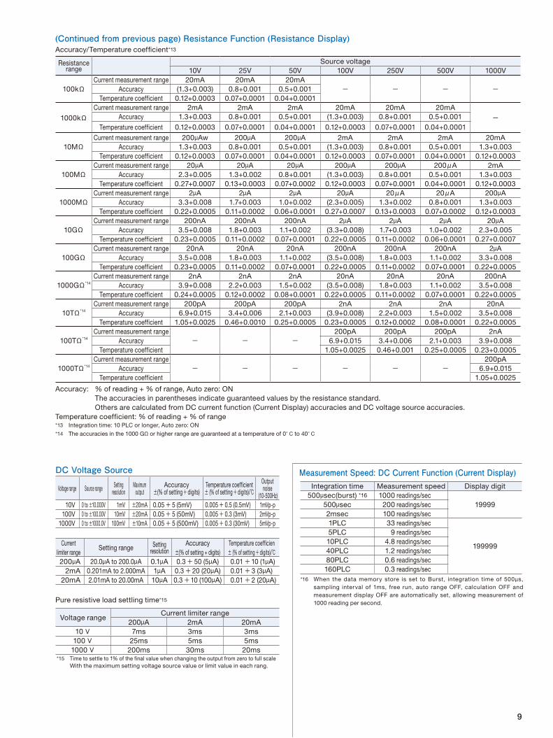
Resistance range
Source voltage10V 25V 50V 100V 250V 500V 1000V
100kΩCurrent measurement range 20mA 20mA 20mA
- - - -Accuracy (1.3+0.003) 0.8+0.001 0.5+0.001Temperature coefficient 0.12+0.0003 0.07+0.0001 0.04+0.0001
1000kΩCurrent measurement range 2mA 2mA 2mA 20mA 20mA 20mA
-Accuracy 1.3+0.003 0.8+0.001 0.5+0.001 (1.3+0.003) 0.8+0.001 0.5+0.001Temperature coefficient 0.12+0.0003 0.07+0.0001 0.04+0.0001 0.12+0.0003 0.07+0.0001 0.04+0.0001
10MΩCurrent measurement range 200μAw 200μA 200μA 2mA 2mA 2mA 20mA
Accuracy 1.3+0.003 0.8+0.001 0.5+0.001 (1.3+0.003) 0.8+0.001 0.5+0.001 1.3+0.003Temperature coefficient 0.12+0.0003 0.07+0.0001 0.04+0.0001 0.12+0.0003 0.07+0.0001 0.04+0.0001 0.12+0.0003
100MΩCurrent measurement range 20μA 20μA 20μA 200μA 200μA 200μA 2mA
Accuracy 2.3+0.005 1.3+0.002 0.8+0.001 (1.3+0.003) 0.8+0.001 0.5+0.001 1.3+0.003Temperature coefficient 0.27+0.0007 0.13+0.0003 0.07+0.0002 0.12+0.0003 0.07+0.0001 0.04+0.0001 0.12+0.0003
1000MΩCurrent measurement range 2μA 2μA 2μA 20μA 20μA 20μA 200μA
Accuracy 3.3+0.008 1.7+0.003 1.0+0.002 (2.3+0.005) 1.3+0.002 0.8+0.001 1.3+0.003Temperature coefficient 0.22+0.0005 0.11+0.0002 0.06+0.0001 0.27+0.0007 0.13+0.0003 0.07+0.0002 0.12+0.0003
10GΩCurrent measurement range 200nA 200nA 200nA 2μA 2μA 2μA 20μA
Accuracy 3.5+0.008 1.8+0.003 1.1+0.002 (3.3+0.008) 1.7+0.003 1.0+0.002 2.3+0.005Temperature coefficient 0.23+0.0005 0.11+0.0002 0.07+0.0001 0.22+0.0005 0.11+0.0002 0.06+0.0001 0.27+0.0007
100GΩCurrent measurement range 20nA 20nA 20nA 200nA 200nA 200nA 2μA
Accuracy 3.5+0.008 1.8+0.003 1.1+0.002 (3.5+0.008) 1.8+0.003 1.1+0.002 3.3+0.008Temperature coefficient 0.23+0.0005 0.11+0.0002 0.07+0.0001 0.22+0.0005 0.11+0.0002 0.07+0.0001 0.22+0.0005
1000GΩ*14
Current measurement range 2nA 2nA 2nA 20nA 20nA 20nA 200nAAccuracy 3.9+0.008 2.2+0.003 1.5+0.002 (3.5+0.008) 1.8+0.003 1.1+0.002 3.5+0.008
Temperature coefficient 0.24+0.0005 0.12+0.0002 0.08+0.0001 0.22+0.0005 0.11+0.0002 0.07+0.0001 0.22+0.0005
10TΩ*14
Current measurement range 200pA 200pA 200pA 2nA 2nA 2nA 20nAAccuracy 6.9+0.015 3.4+0.006 2.1+0.003 (3.9+0.008) 2.2+0.003 1.5+0.002 3.5+0.008
Temperature coefficient 1.05+0.0025 0.46+0.0010 0.25+0.0005 0.23+0.0005 0.12+0.0002 0.08+0.0001 0.22+0.0005
100TΩ*14
Current measurement range- - -
200pA 200pA 200pA 2nAAccuracy 6.9+0.015 3.4+0.006 2.1+0.003 3.9+0.008
Temperature coefficient 1.05+0.0025 0.46+0.001 0.25+0.0005 0.23+0.0005
1000TΩ*14
Current measurement range- - - - - -
200pAAccuracy 6.9+0.015
Temperature coefficient 1.05+0.0025
Accuracy/Temperature coefficient*13
Accuracy: % of reading + % of range, Auto zero: ON The accuracies in parentheses indicate guaranteed values by the resistance standard.
Others are calculated from DC current function (Current Display) accuracies and DC voltage source accuracies.Temperature coefficient: % of reading + % of range*13 Integration time: 10 PLC or longer, Auto zero: ON
*14 The accuracies in the 1000 GΩ or higher range are guaranteed at a temperature of 0°C to 40°C
DC Voltage Source
Current limiter range
Setting range Setting resolution
Accuracy±(% of setting + digits)
Temperature coefficien± (% of setting+ digits)/
200μA 20.0μA to 200.0μA 0.1μA 0.3+ 50 (5μA) 0.01 +10 (1μA)2mA 0.201mA to 2.000mA 1μA 0.3+ 20 (20μA) 0.01 + 3 (3μA)
20mA 2.01mA to 20.00mA 10μA 0.3+10 (100μA) 0.01 + 2 (20μA)
Pure resistive load settling time*15
Voltage rangeCurrent limiter range
200μA 2mA 20mA10V 7ms 3ms 3ms
100V 25ms 5ms 5ms1000V 200ms 30ms 20ms
*15 Time to settle to 1% of the final value when changing the output from zero to full scale With the maximum setting voltage source value or limit value in each rang.
Measurement Speed: DC Current Function (Current Display)
Voltage range Source range Setting resolution
Maximum output
Accuracy±(% of setting+ digits)
Temperature coefficient± (% of setting+ digits)/
Output noise
(10-500Hz)10V 0 to ±10.000V 1mV ±20mA 0.05+ 5 (5mV) 0.005+ 0.5 (0.5mV) 1mVp-p
100V 0 to ±100.00V 10mV ±20mA 0.05+ 5 (50mV) 0.005+ 0.3 (3mV) 2mVp-p1000V 0 to ±1000.0V 100mV ±10mA 0.05+ 5 (500mV) 0.005+ 0.3 (30mV) 5mVp-p
Integration time Measurement speed Display digit500μsec(burst) *16 1000 readings/sec
19999500μsec 200 readings/sec2msec 100 readings/sec1PLC 33 readings/sec
199999
5PLC 9 readings/sec10PLC 4.8 readings/sec40PLC 1.2 readings/sec80PLC 0.6 readings/sec160PLC 0.3 readings/sec
*16 When the data memory store is set to Burst, integration time of 500µs, sampling interval of 1ms, free run, auto range OFF, calculation OFF and measurement display OFF are automatically set, allowing measurement of 1000 reading per second.
(Continued from previous page) Resistance Function (Resistance Display)
10
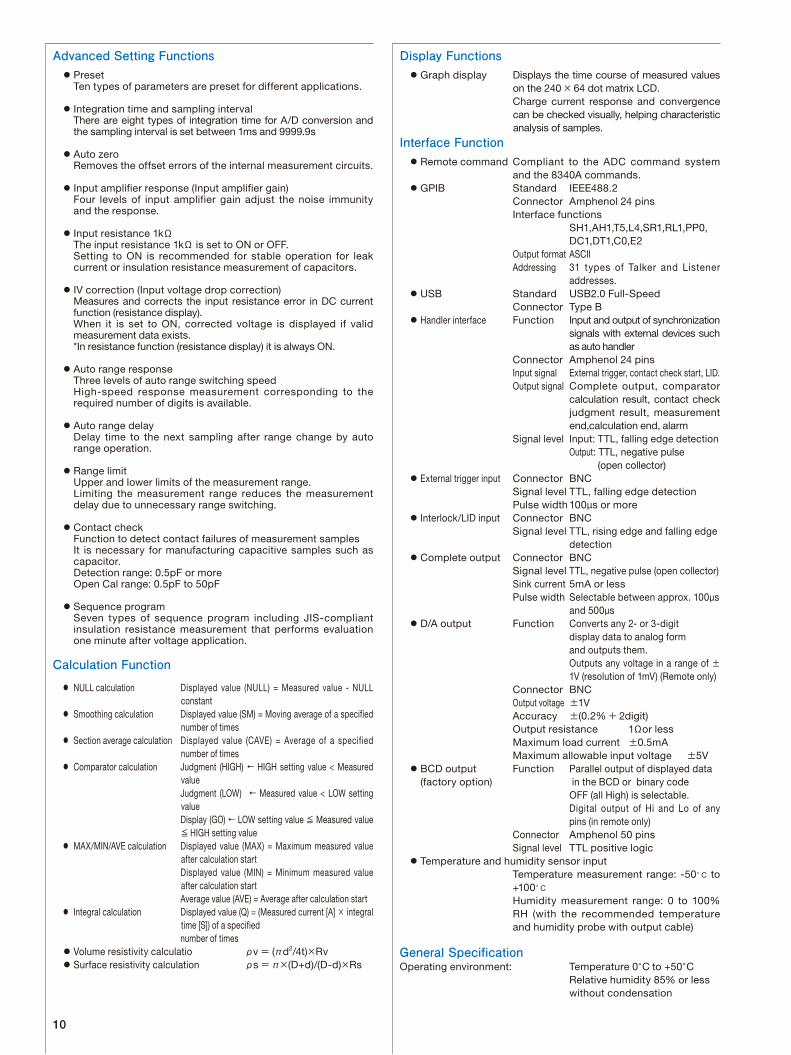
Display Functions Graph display Displays the time course of measured values
on the 240 × 64 dot matrix LCD. Charge current response and convergence
can be checked visually, helping characteristic analysis of samples.
Interface Function Remote command Compliant to the ADC command system
and the 8340A commands. GPIB Standard IEEE488.2 Connector Amphenol 24 pins Interface functions SH1,AH1,T5,L4,SR1,RL1,PP0, DC1,DT1,C0,E2 Output format ASCII Addressing 31 types of Talker and Listener
addresses. USB Standard USB2.0 Full-Speed Connector Type B Handler interface Function Input and output of synchronization
signals with external devices such as auto handler
Connector Amphenol 24 pins Input signal External trigger, contact check start, LID. Output signal Complete output, comparator
calculation result, contact check judgment result, measurement end,calculation end, alarm
Signal level Input: TTL, falling edge detection Output: TTL, negative pulse (open collector) External trigger input Connector BNC Signal level TTL, falling edge detection Pulse width 100µs or more Interlock/LID input Connector BNC Signal level TTL, rising edge and falling edge detection Complete output Connector BNC Signal level TTL, negative pulse (open collector) Sink current 5mA or less Pulse width Selectable between approx. 100µs and 500µs D/A output Function Converts any 2- or 3-digit display data to analog form and outputs them. Outputs any voltage in a range of ±
1V (resolution of 1mV) (Remote only) Connector BNC Output voltage ±1V Accuracy ±(0.2%+ 2digit) Output resistance 1Ωor less Maximum load current ±0.5mA Maximum allowable input voltage ±5V BCD output Function Parallel output of displayed data (factory option) in the BCD or binary code OFF (all High) is selectable. Digital output of Hi and Lo of any
pins (in remote only) Connector Amphenol 50 pins Signal level TTL positive logic Temperature and humidity sensor input Temperature measurement range: -50°C to
+100°C Humidity measurement range: 0 to 100%
RH (with the recommended temperature and humidity probe with output cable)
General SpecificationOperating environment: Temperature 0°C to +50°C Relative humidity 85% or less
without condensation
Advanced Setting Functions Preset Ten types of parameters are preset for different applications.
Integration time and sampling interval There are eight types of integration time for A/D conversion and
the sampling interval is set between 1ms and 9999.9s
Auto zero Removes the offset errors of the internal measurement circuits.
Input amplifier response (Input amplifier gain) Four levels of input amplifier gain adjust the noise immunity
and the response.
Input resistance 1kΩ The input resistance 1kΩ is set to ON or OFF. Setting to ON is recommended for stable operation for leak
current or insulation resistance measurement of capacitors.
IV correction (Input voltage drop correction) Measures and corrects the input resistance error in DC current
function (resistance display). When it is set to ON, corrected voltage is displayed if valid
measurement data exists. *In resistance function (resistance display) it is always ON.
Auto range response Three levels of auto range switching speed High-speed response measurement corresponding to the
required number of digits is available.
Auto range delay Delay time to the next sampling after range change by auto
range operation.
Range limit Upper and lower limits of the measurement range. Limiting the measurement range reduces the measurement
delay due to unnecessary range switching.
Contact check Function to detect contact failures of measurement samples It is necessary for manufacturing capacitive samples such as
capacitor. Detection range: 0.5pF or more Open Cal range: 0.5pF to 50pF
Sequence program Seven types of sequence program including JIS-compliant
insulation resistance measurement that performs evaluation one minute after voltage application.
Calculation Function
NULL calculation Displayed value (NULL) = Measured value - NULL constant
Smoothing calculation Displayed value (SM) = Moving average of a specified number of times
Section average calculation Displayed value (CAVE) = Average of a specified number of times
Comparator calculation Judgment (HIGH) ← HIGH setting value < Measured value
Judgment (LOW) ← Measured value < LOW setting value
Display (GO) ← LOW setting value ≦ Measured value ≦ HIGH setting value
MAX/MIN/AVE calculation Displayed value (MAX) = Maximum measured value after calculation start
Displayed value (MIN) = Minimum measured value after calculation start
Average value (AVE) = Average after calculation start Integral calculation Displayed value (Q) = (Measured current [A] × integral
time [S]) of a specified number of times Volume resistivity calculatio ρv= (πd2/4t)×Rv Surface resistivity calculation ρs=π×(D+d)/(D-d)×Rs
11
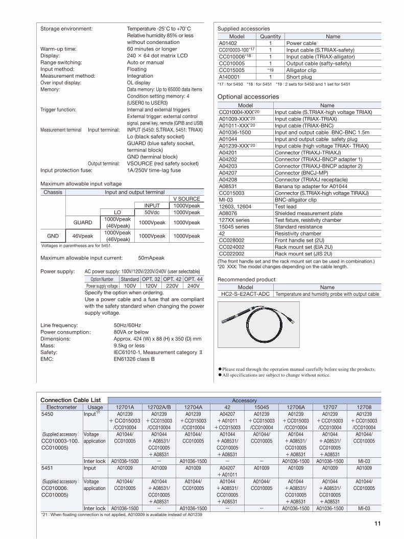
Storage environment: Temperature -25°C to +70°C Relative humidity 85% or less
without condensationWarm-up time: 60 minutes or longerDisplay: 240 × 64 dot matrix LCDRange switching: Auto or manualInput method: FloatingMeasurement method: IntegrationOver input display: OL displayMemory: Data memory: Up to 65000 data items Condition setting memory: 4
(USER0 to USER3)Trigger function: Internal and external triggers External trigger: external control
signal, panel key, remote (GPIB and USB)Measurement terminal Input terminal: INPUT (5450: S.TRIAX, 5451: TRIAX) Lo (black safety socket) GUARD (blue safety socket,
terminal block) GND (terminal block) Output terminal: VSOURCE (red safety socket)Input protection fuse: 1A/250V time-lag fuse
Maximum allowable input voltage
Maximum allowable input current: 50mApeak
Power supply: AC power supply: 100V/120V/220V/240V (user selectable)
Option Number Standard OPT. 32 OPT. 42 OPT. 44Power supply voltage 100V 120V 220V 240V
Specify the option when ordering. Use a power cable and a fuse that are compliant
with the safety standard when changing the power supply voltage.
Line frequency: 50Hz/60HzPower consumption : 80VA or belowDimensions: Approx. 424 (W) x 88 (H) x 350 (D) mmMass: 9.5kg or lessSafety: IEC61010-1, Measurement category ⅡEMC: EN61326 class B
Supplied accessories
Model Quantity NameA01402 1 Power cableCC010003-100*17 1 Input cable (S.TRIAX-safety)CC010006*18 1 Input cable (TRIAX-alligator)CC010005 1 Output cable (safty-safety)CC015005 *19 Alligator clipA140001 1 Short plug
*17:for 5450 *18:for 5451 *19:2 sets for 5450 and 1 set for 5451
Optional accessories
Recommended product
Chassis Input and output terminalV SOURCE
INPUT 1000VpeakLO 50Vdc 1000Vpeak
GUARD1000Vpeak (46Vpeak)
1000Vpeak 1000Vpeak
GND 46Vpeak1000Vpeak (46Vpeak)
1000Vpeak 1000Vpeak
Voltages in parentheses are for 5451.
Model NameHC2-S-E2ACT-ADC Temperature and humidity probe with output cable
Please read through the operation manual carefully before using the products. All specifications are subject to change without notice.
Model NameCC010004-XXX*20 Input cable (S.TRIAX-high voltage TRIAX)A01009-XXX*20 Input cable (TRIAX-TRIAX)A01011-XXX*20 Input cable (TRIAX-BNC)A01036-1500 Input and output cable BNC-BNC 1.5mA01044 Input and output cable safety plugA01239-XXX*20 Input cable (high voltage TRIAX- TRIAX)A04201 Connector (TRIAXJ-TRIAXJ)A04202 Connector (TRIAXJ-BNCP adapter 1)A04203 Connector (TRIAXJ-BNCP adapter 2)A04207 Connector (BNCJ-MP)A04208 Connector (TRIAXJ receptacle)A08531 Banana tip adapter for A01044CC015003 Connector (S.TRIAX-high voltage TIRAXJ)MI-03 BNC-alligator clip12603, 12604 Test leadA08076 Shielded measurement plate127XX series Test fixture, resistivity chamber15045 series Standard resistance42 Resistivity chamberCC028002 Front handle set (2U)CC024002 Rack mount set (EIA 2U)CC022002 Rack mount set (JIS 2U)
(The front handle set and the rack mount set can be used in combination.)*20 XXX: The model changes depending on the cable length.
Connection Cable List AccessoryElectrometer Usage 12701A 12702A/B 12704A 42 15045 12706A 12707 12708
5450 Input*21 A01239+CC015003
/CC010004
A01239+CC015003/CC010004
A01239+CC015003/CC010004
A04207+A01011+CC015003
A01239+CC015003/CC010004
A01239+CC015003/CC010004
A01239+CC015003/CC010004
A01239+CC015003/CC010004
(Supplied accessory:CC010003-100、CC010005)
Voltageapplication
A01044/CC010005
A01044+A08531/CC010005+A08531
A01044/CC010005
A01044+A08531/CC010005+A08531
A01044/CC010005
A01044+A08531/CC010005+A08531
A01044+A08531/CC010005+A08531
A01044/CC010005
Inter lock A01036-1500 - A01036-1500 - - A01036-1500 A01036-1500 MI-035451 Input A01009 A01009 A01009 A04207
+A01011A01009 A01009 A01009 A01009
(Supplied accessory:CC010006、CC010005)
Voltageapplication
A01044/CC010005
A01044+A08531/CC010005+A08531
A01044/CC010005
A01044+A08531/CC010005+A08531
A01044/CC010005
A01044+A08531/CC010005+A08531
A01044+A08531/CC010005+A08531
A01044/CC010005
Inter lock A01036-1500 - A01036-1500 - - A01036-1500 A01036-1500 MI-03*21:When floating connection is not applied, A010009 is available instead of A01239

© 2014 ADC CORPORATION Printed in Japan 5450/5451-NP2E Aug. '14 A
Head Office Shoei Bldg, 3-6-12, Kyobashi, Chuo-ku, Tokyo 104-0031, Japan Phone: +81-3-6272-4433 Fax: +81-3-6272-4437
Higashimatsuyama Office (R&D Center) 77-1, Miyako Namegawa-machi, Hiki-gun, Saitama 355-0812, Japan Phone: +81-493-56-4433 Fax: +81-493-57-1092
E-mail : [email protected] URL : http://www.adcmt-e.com
Top Related