

γλώσσες
Σελίδες
Νομικός

M d l 31 Module 31: InterferenceInterference
1
Module 31: Outline
InterferenceInterference
2
= = =
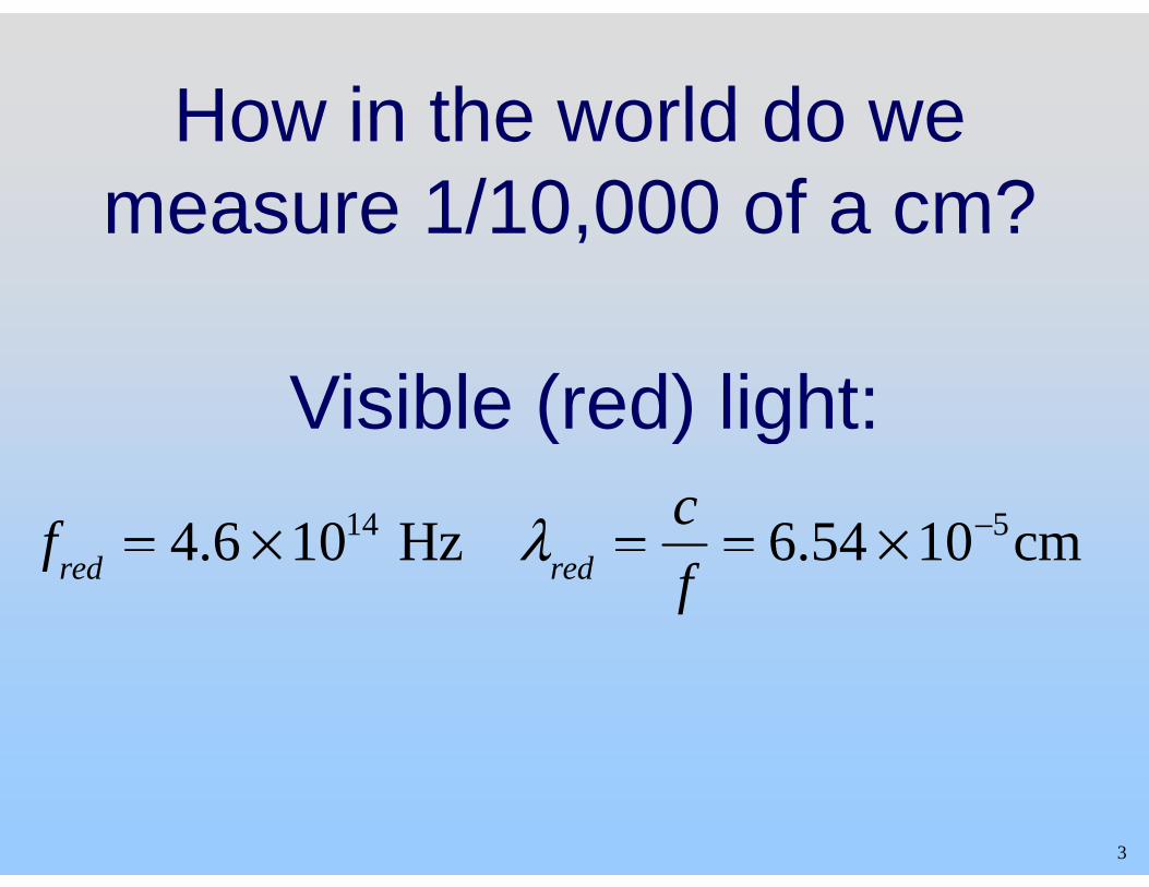
How in the world do weHow in the world do we measure 1/10,000 of a cm?measure 1/10,000 of a cm?
Visible (red) light:( ) g
f = 4 6 × 10¹⁴ Hz λ = c = 6 54 × 10−5 cmfred 4.6 × 10 Hz λred f 6.54 × 10 cm
3
We Use InterferenceWe Use Interference
This is also how we know that light is a wave phenomena
Brief Comment: What is light?Brief Comment: What is light?
4
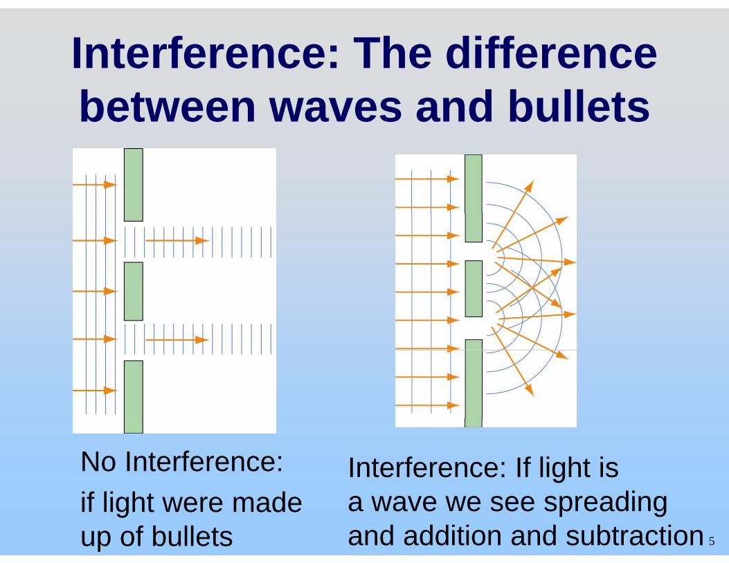
Interference: The difference between waves and bullets
No Interference: Interference: If light is
5
if light were made up of bullets
a wave we see spreading and addition and subtraction
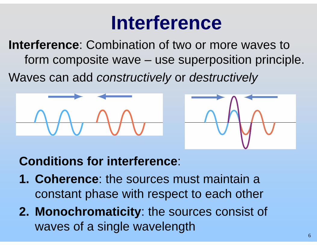
Interference Interference: Combination of two or more waves to
form composite wave – use superposition principle. form composite wave use superposition principle. Waves can add constructively or destructively
Conditions for interference: 1. Coherence: the sources must maintain a 1. Coherence: the sources must maintain a
constant phase with respect to each other 2 Monochromaticity: the sources consist of
6
2. Monochromaticity: the sources consist of waves of a single wavelength
D t ti Demonstration: Microwave InterferenceMicrowave Interference
7
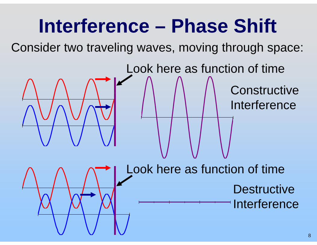
Interference – Phase Shift Consider two traveling waves, moving through space:
Look here as function of time
ConstructiveConstructive Interference
Look here as function of time Destructive Interference
8
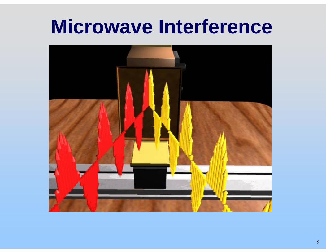
Microwave Interference
9
Interference – Phase Shift
What can introduce a phase shift?What can introduce a phase shift?
1 F diff t t f h1. From different, out of phase sources 2 Sources in phase but travel different 2. Sources in phase, but travel different
distances 1. Thin films 2 Coming from different locations 2. Coming from different locations
10
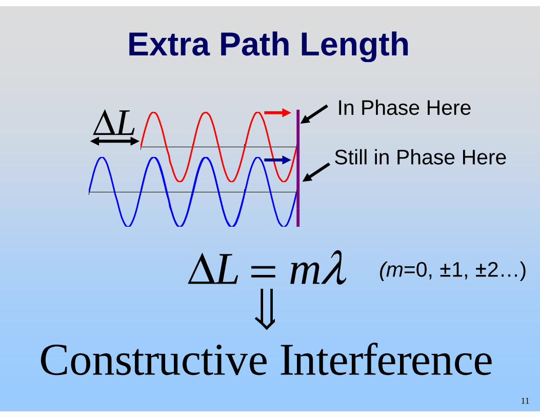
Extra Path Lengthg
In Phase HereIn Phase HereLΔStill in Phase HereStill in Phase Here
ΔL λΔL = mλ ⇓
(m=0, ±1, ±2…)
⇓ Constructive Interference
11
Constructive Interference
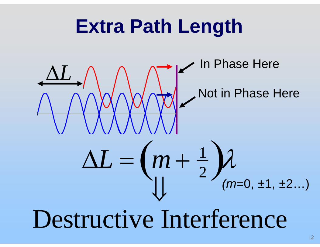
Extra Path Lengthg
In Phase HereIn Phase HereLΔNot in Phase Here Not in Phase Here
ΔL 1( )λΔL = m + 12( )λ
⇓ (m=0 ±1 ±2 )⇓D t ti I t f
(m=0, ±1, ±2…)
12 Destructive Interference
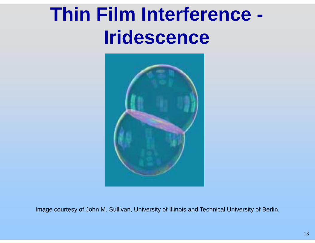
Thin Film Interference -I idIridescence
Image courtesy of John M Sullivan University of Illinois and Technical University of Berlin
13
Image courtesy of John M. Sullivan, University of Illinois and Technical University of Berlin.
Thin Film Interference -I idIridescence
•Bubbles •Butterfly Wings •Oil on Puddles•Oil on Puddles
14
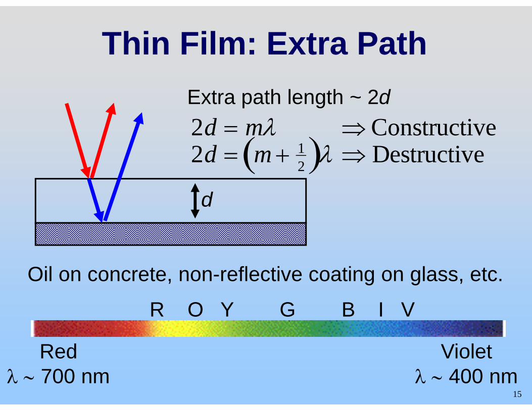
Thin Film: Extra PathExtra path length ~ 2dp g2d = mλ ⇒ Constructive2d = m + 1( )λ ⇒ Destructive
d
2d = m + 2( )λ ⇒ Destructive
d
Oil on concrete, non-reflective coating on glass, etc.
R O Y G B I V
Red Violet
R O Y G B I V
15
Redλ ∼ 700 nm
Violetλ ∼ 400 nm
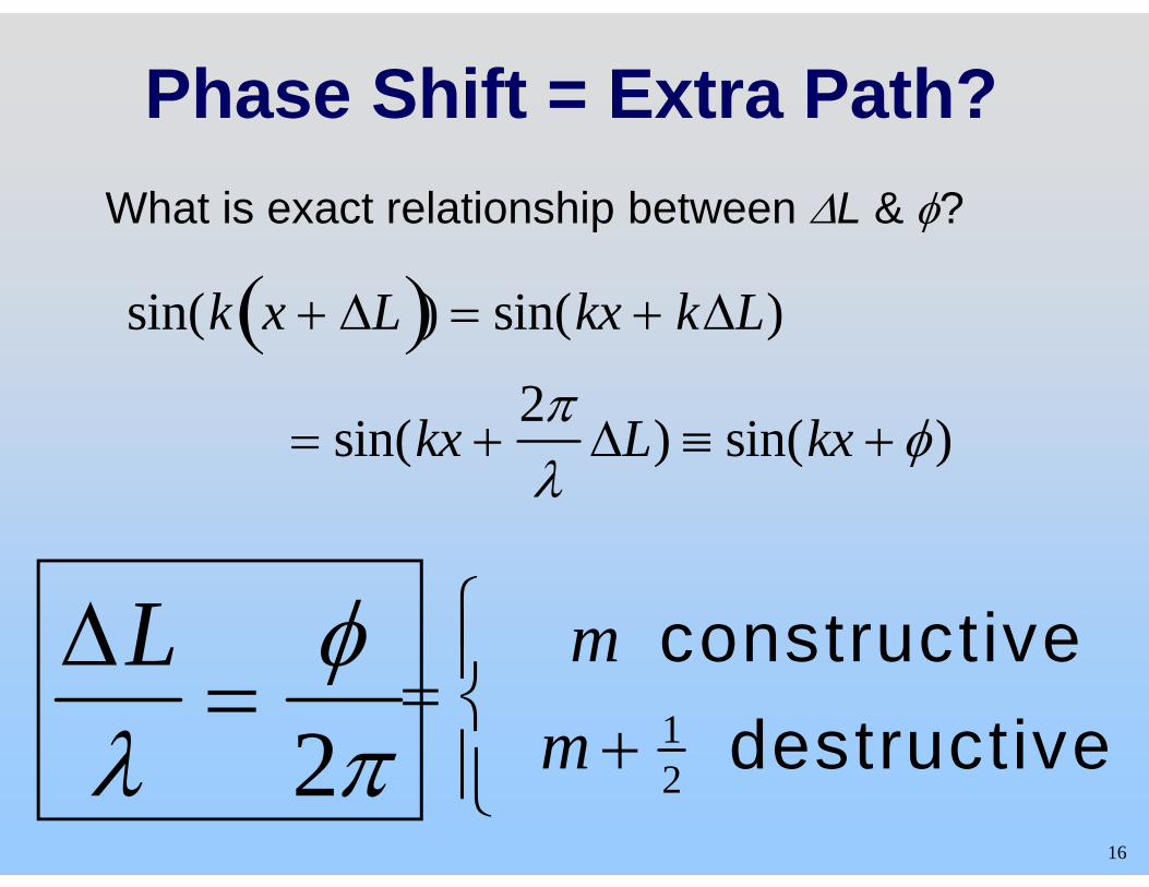
Phase Shift = Extra Path?What is exact relationship between ΔL & φ?p φ
sin(k x + ΔL( )) = sin(kx + kΔL)( ( )) ( )
= sin(kx +2π
ΔL) ≡ sin(kx + φ)
= sin(kx +λΔL) ≡ sin(kx + φ)
ΔL φ m constructive⎧⎪ΔLλ
=φ2π
=m constructive
m + 12 destructive⎨
⎪
⎩⎪16
λ 2π m + 2 destructive⎩⎪
Two Transmitters
17
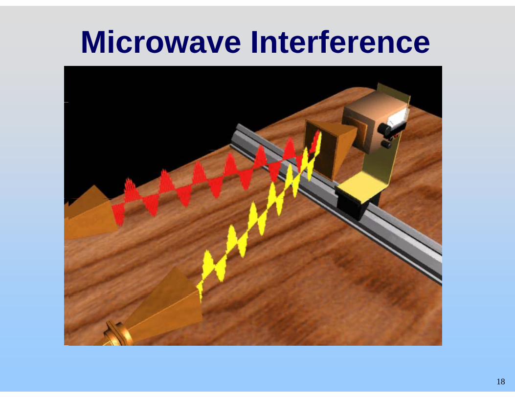
Microwave Interference
18
= =
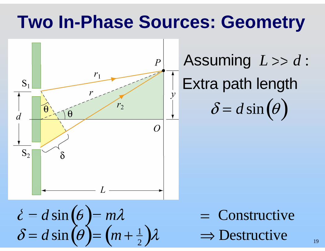
Two In-Phase Sources: Geometry
Assuming L >> d :Assuming L >> d : Extra path length
δ = d sin θ( )
δ = d sin θ( )= mλ ⇒ Constructive 19
δ d sin θ( ) mλ ⇒ Constructive δ = d sin θ( )= m + 1
2( )λ ⇒ Destructive
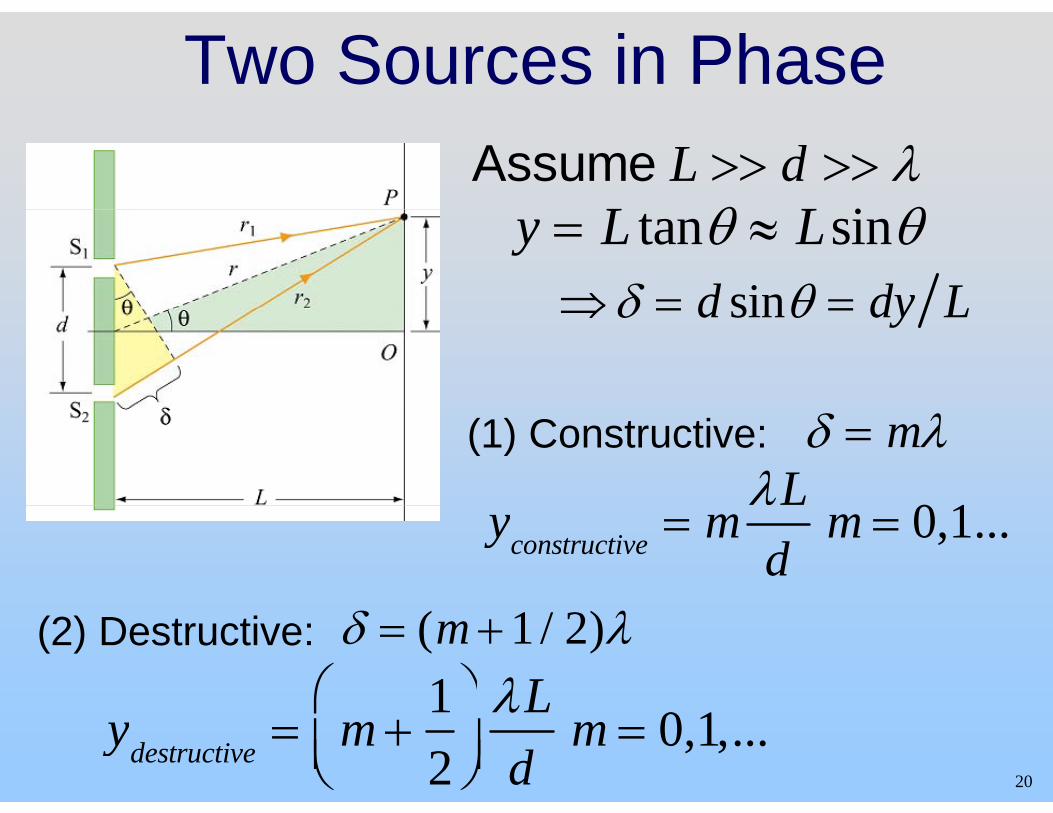
Two Sources in PhaseAssume L >> d >> λ
L θ L i θy = L tanθ ≈ Lsinθ⇒δ = d sinθ = dy L⇒δ = d sinθ = dy L
(1) Constructive:λL
0 1
δ = mλ
yconstructive = md
m = 0,1...
(2) Destructive: δ = (m +1 / 2)λ1⎛ ⎞ λL
20
ydestructive = m +12
⎛⎝⎜
⎞⎠⎟λLd
m = 0,1,...
C t Q ti Q ti Concept Question Question Two Slits with WidthTwo Slits with Width
21
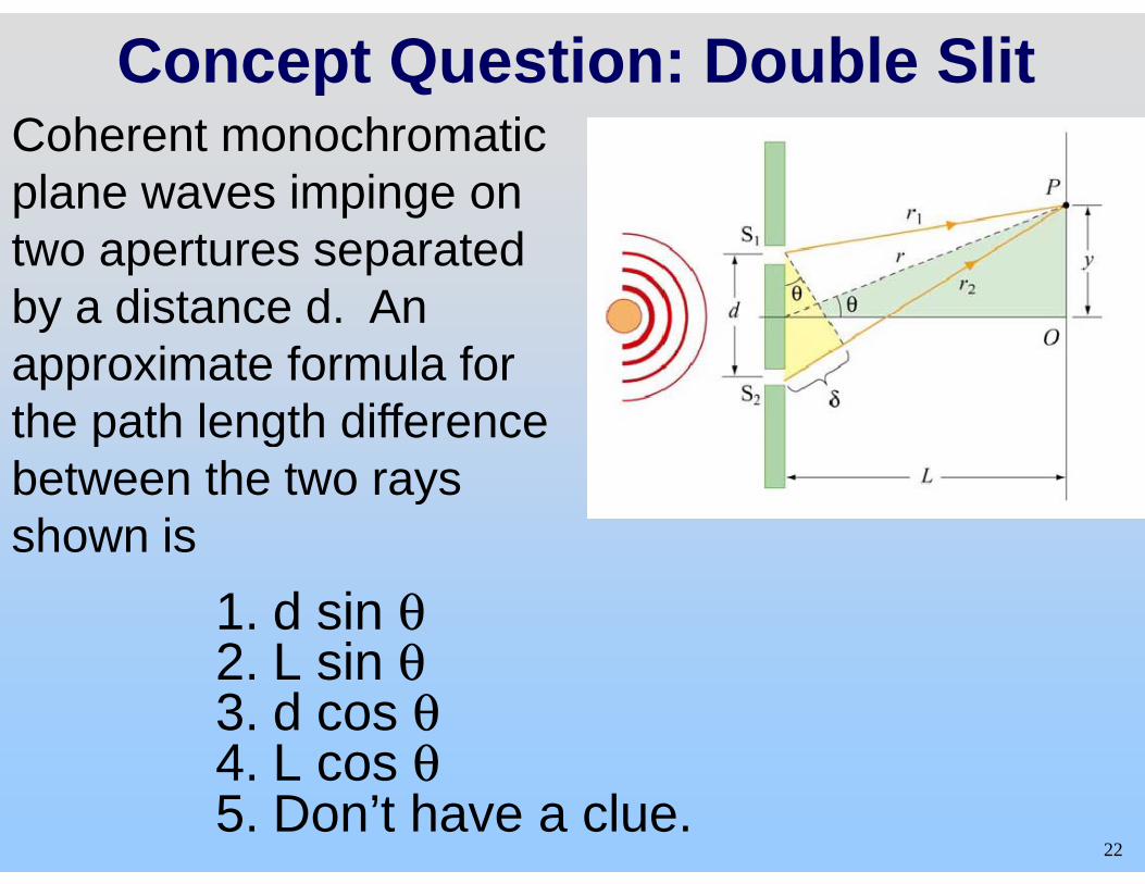
Concept Question: Double Slit C h t h ti Coherent monochromatic plane waves impinge on two apertures separated by a distance d. An approximate formula for the path length difference p g between the two rays shown isshown is
1. d sin θ 2 L sin θ2. L sin θ 3. d cos θ 4 L cos θ
22
4. L cos θ 5. Don’t have a clue.
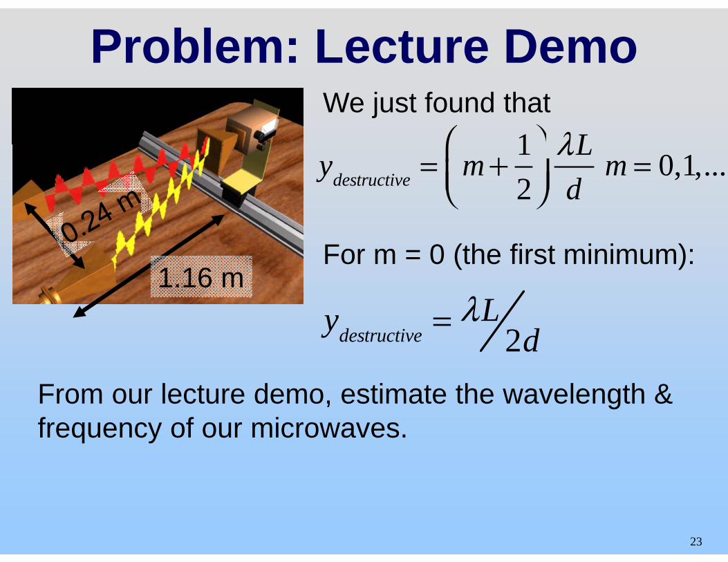
Problem: Lecture Demo
1⎛ ⎞ λL We just found that
ydestructive = m 1 2
⎛ ⎝⎜
⎞ ⎠⎟
λL d
m = 0,1,...
For m = 0 (the first minimum): 1 16 m
ydestructive = λL 2d
1.16 m
From our lecture demo, estimate the wavelength & f f i
2d
frequency of our microwaves.
23
+
Th Li ht E i l tThe Light Equivalent: Two SlitsTwo Slits
24
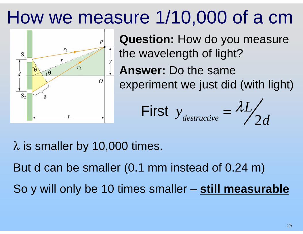
How we measure 1/10,000 of a cm Question: How do you measure the wavelength of light? Answer: Do the same experiment we just did (with light)p j ( g )
First ydestructive = λL 2d
λ is smaller by 10 000 times
ydestructive 2d
λ is smaller by 10,000 times.
But d can be smaller (0.1 mm instead of 0.24 m)( )
So y will only be 10 times smaller – still measurable
25
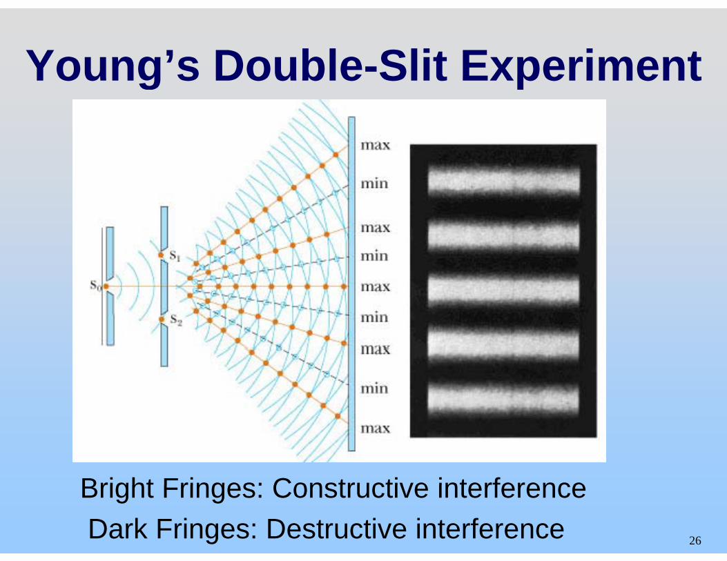
Young’s Double-Slit Experiment Young s Double Slit Experiment
Bright Fringes: Constructive interference 26
Bright Fringes: Constructive interference Dark Fringes: Destructive interference
L t D t ti Lecture Demonstration: Double SlitDouble Slit
27
MIT OpenCourseWarehttp://ocw.mit.edu
8.02SC Physics II: Electricity and Magnetism Fall 2010
For information about citing these materials or our Terms of Use, visit: http://ocw.mit.edu/terms.
Top Related