


γλώσσες
Σελίδες
Νομικός

1
Prof. Maria PapadopouliUniversity of Crete
ICS-FORTHhttp://www.ics.forth.gr/mobile
Lectures on Wireless Networks & Mobile ComputingCS 439 & 539
ΠεριεχόμεναΕισαγωγή στις θεμελιώδης έννοιες σχετικά με τα παρακάτω:• ασύρματα δίκτυα, τόσο στο φυσικό όσο και στο MAC layer (radio propagation,
channel, modulation)• συστήματα εύρεσης θέσης (positioning systems)• ασύρματες τεχνολογίες (πχ IEEE802.11, WiMAX, UWB, Bluetooth, RF tags, sensors,
LTE)• αρχιτεκτονικές/μοντέλα πρόσβασης
– στην πληροφορία (πχ mobile peer-to-peer systems, infostations) , και – ασύρματων δικτύων (πχ ad hoc, mesh, sensor, infrastructure networks),
• πρωτόκολλα δρομολόγησης σε ασύρματα δίκτυα (routing protocols)• εφαρμογές για κινητά υπολογιστικά συστήματα (πχ social networking & location-
based εφαρμογές πάνω σε Android, ambient intelligence)• εποπτεία ασύρματων δικτύων και ανάλυση της απόδοσης τους• θέματα μοντελοποίησης των ασύρματων δικτύων• cognitive radios• Spectrum & wireless access markets and business issues 2
Short CV
Originally from Heraklio, Crete, Greece• B.Sc. University of Crete (1992)• M.Sc. New York University (1994)• Ph.D. Columbia University (2002) Ph.D. Thesis “Resource sharing in mobile wireless networks” Advisor: Prof. Henning Schulzrinne
• Assistant Professor, University of North Carolina at Chapel Hill (2002-2006)• Research Associate, Foundation for Research & Technology-Hellas (2004-)• Associate Professor, University of Crete (2005-)• Guest Full Professor, KTH Royal Institute of Technology (2011-)
Research interests: wireless networks, measurements & modeling, mobile computing, positioningWireless access markets
3
Εισαγωγικά - Δομή
4
Δεν είναι ένα συνηθισμένο μάθημα!
Οι φοιτητές θα χρειαστεί να διαβάσουν από διάφορες πηγές:• Υλικό online (διαλέξεις, papers)• Κεφάλαια βιβλίων
Περιλαμβάνει τόσο θεωρητικές όσο και πρακτικές ασκήσεις.Θα γίνουν διαλέξεις από τους φοιτητέςΘα γίνουν διαλέξεις από τους μεταπτυχιακούς φοιτητές/βοηθούςκαι εργαστήρια
Αν έχουμε Erasmus φοιτητές, οι διαλέξεις θα γίνονται στα αγγλικά
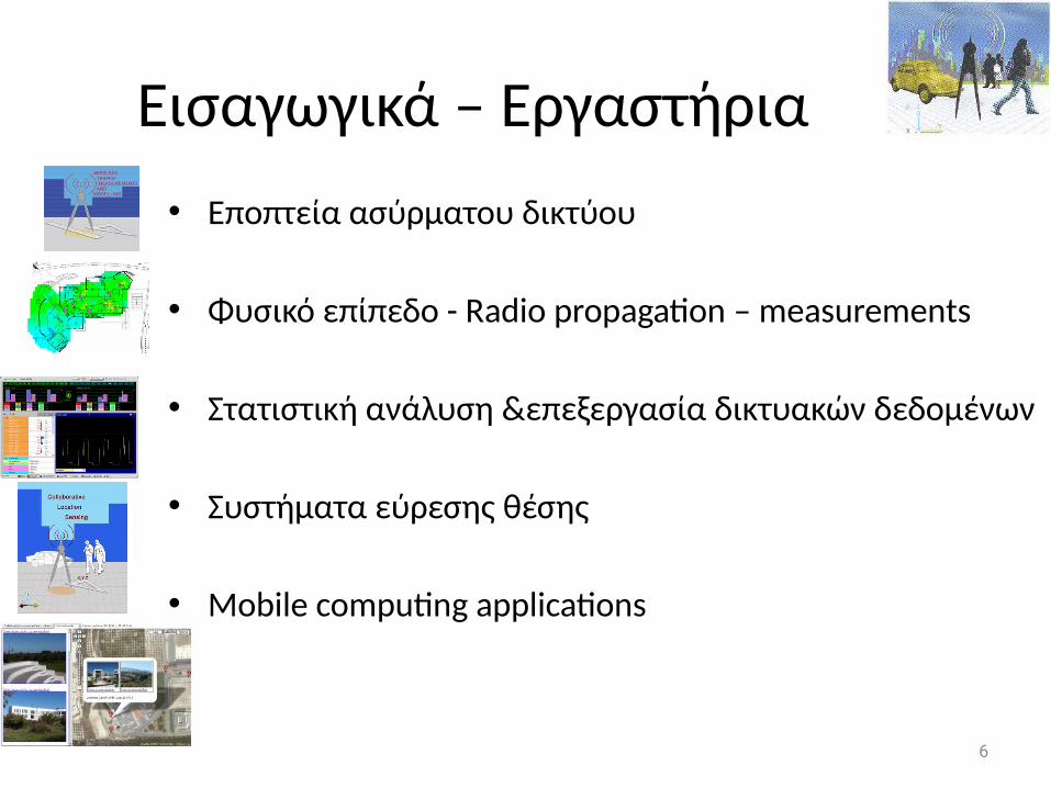
Εισαγωγικά – Εργαστήρια• Εποπτεία ασύρματου δικτύου
• Φυσικό επίπεδο - Radio propagation – measurements
• Στατιστική ανάλυση &επεξεργασία δικτυακών δεδομένων
• Συστήματα εύρεσης θέσης
• Mobile computing applications
6
Project 1: Εποπτεία ασύρματου δικτύου
7
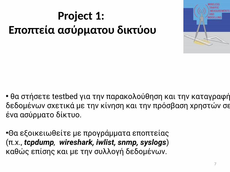
• θα στήσετε testbed για την παρακολούθηση και την καταγραφή δεδομένων σχετικά με την κίνηση και την πρόσβαση χρηστών σε ένα ασύρματο δίκτυο.
•Θα εξοικειωθείτε με προγράμματα εποπτείας (π.χ., tcpdump, wireshark, iwlist, snmp, syslogs) καθώς επίσης και με την συλλογή δεδομένων.
Project 2: Στατιστική ανάλυση& επεξεργασία δικτυακών
δεδομένων
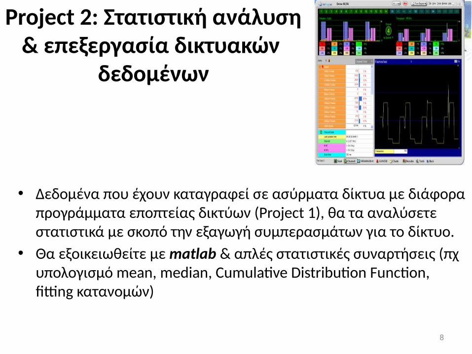
• Δεδομένα που έχουν καταγραφεί σε ασύρματα δίκτυα με διάφορα προγράμματα εποπτείας δικτύων (Project 1), θα τα αναλύσετε στατιστικά με σκοπό την εξαγωγή συμπερασμάτων για το δίκτυο.
• Θα εξοικειωθείτε με matlab & απλές στατιστικές συναρτήσεις (πχ υπολογισμό mean, median, Cumulative Distribution Function, fitting κατανομών)
8
Project 3: Φυσικό επίπεδο – Radio propagation – measurements
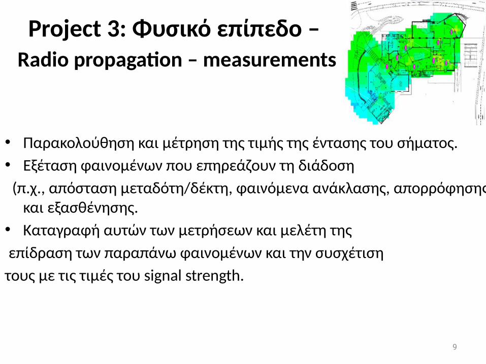
• Παρακολούθηση και μέτρηση της τιμής της έντασης του σήματος. • Εξέταση φαινομένων που επηρεάζουν τη διάδοση (π.χ., απόσταση μεταδότη/δέκτη, φαινόμενα ανάκλασης, απορρόφησης
και εξασθένησης. • Καταγραφή αυτών των μετρήσεων και μελέτη της επίδραση των παραπάνω φαινομένων και την συσχέτιση τους με τις τιμές του signal strength.
9
Project 4 – Συστήματα εύρεσης θέσης
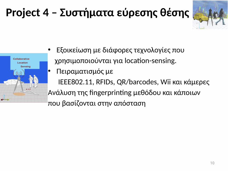
• Εξοικείωση με διάφορες τεχνολογίες που χρησιμοποιούνται για location-sensing. • Πειραματισμός με ΙΕΕΕ802.11, RFIDs, QR/barcodes, Wii και κάμερεςΑνάλυση της fingerprinting μεθόδου και κάποιωνπου βασίζονται στην απόσταση
10
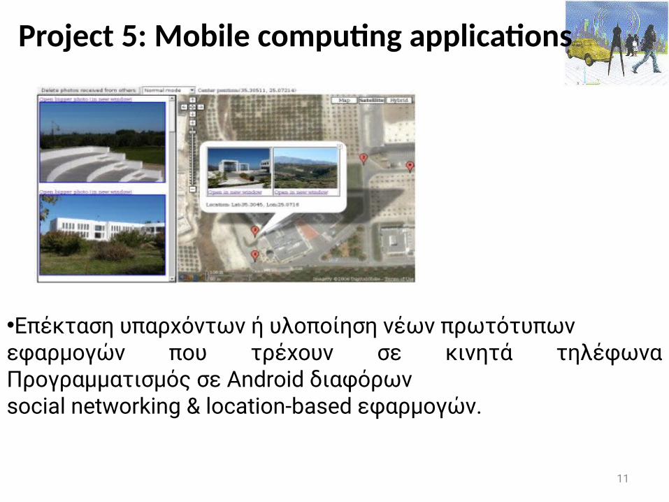
Project 5: Mobile computing applications
11
•Επέκταση υπαρχόντων ή υλοποίηση νέων πρωτότυπωνεφαρμογών που τρέχουν σε κινητά τηλέφωνα Προγραμματισμός σε Android διαφόρων social networking & location-based εφαρμογών.
Research Projects
• Development of the u-map: a user-centric grass-root data base with cross-layer information about user access and quality-of-experience (QoE) for various applications (systems project)
• Spectrum markets– Business-driven assessment of spectrum markets (in
matlab)
12
Εισαγωγικά - Βαθμός
• Εργαστηριακές ασκήσεις (projects) 40% θα δοθεί κώδικας έτοιμος, πάνω στον οποίο θα
υλοποιήσετε το project σαςΟμάδες 2-3 ατόμων, και ατομικά projectsSharing of the infrastructure (e.g., Android phones)• Τελικός (Final exam) 35-50% (βαθμός > 4.5, για να
περάσει κάποιος το μάθημα)• Πρόοδος (15%) προαιρετική• Παρουσίαση 10% (Presentation)
13
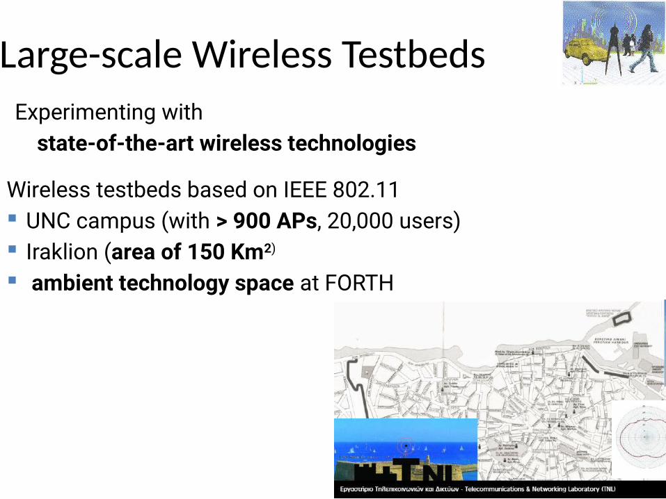
Large-scale Wireless TestbedsExperimenting with state-of-the-art wireless technologies
Wireless testbeds based on IEEE 802.11 UNC campus (with > 900 APs, 20,000 users) Iraklion (area of 150 Km2) ambient technology space at FORTH
15
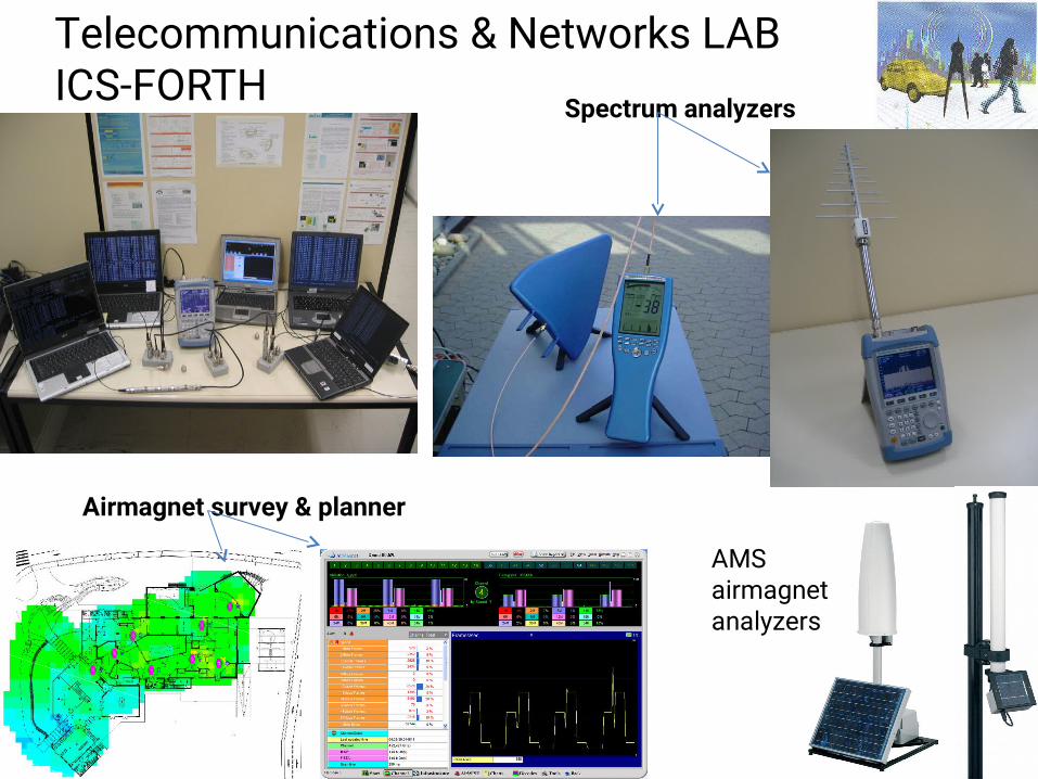
Airmagnet survey & planner
Spectrum analyzers
Telecommunications & Networks LAB ICS-FORTH
AMSairmagnetanalyzers
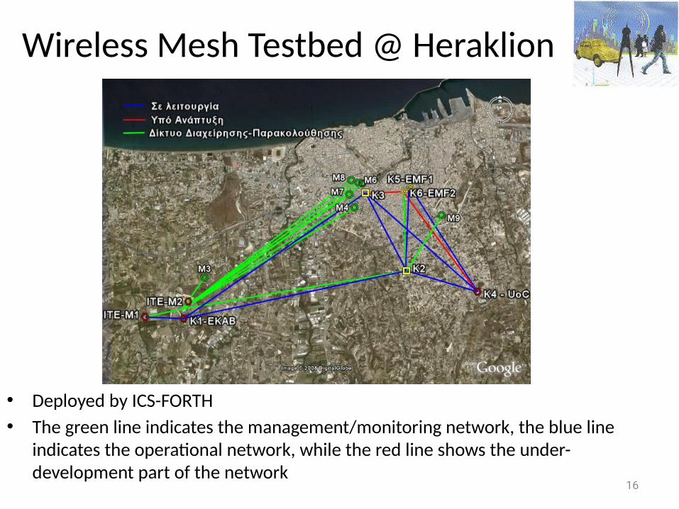
Wireless Mesh Testbed @ Heraklion
• Deployed by ICS-FORTH• The green line indicates the management/monitoring network, the blue line
indicates the operational network, while the red line shows the under-development part of the network
16
Agenda
• Introduction on Mobile Computing & Wireless Networks• Wireless Networks - Physical Layer• IEEE 802.11 MAC• Wireless Network Measurements & Modeling • Location Sensing• Performance of VoIP over wireless networks• Mobile Peer-to-Peer computing
17
General Objectives
• Build some background on wireless networks, IEEE802.11, positioning, mobile computing
• Explore some research projects and possibly research collaborations
18
19
Lecture on Introduction on Mobile Computing
Prof. Maria PapadopouliUniversity of Crete
ICS-FORTHhttp://www.ics.forth.gr/mobile
Wireless Networks & Mobile Computing
20
Profound technologies
“ The most profound technologies are those that disappear. They weave themselves into the fabric of everyday life until they are indistinguishable from it."
Mark Weiser, 1991
21
Weiser’s vision
• The creation of environments saturated with computing and communication capability yet gracefully integrated with human users
• After two decades of hardware progress, many critical elements of pervasive computing that were exotic in 1991 are now viable commercial products: handheld and wearable computers, wireless LANs, and devices to sense and control appliances
• Well-positioned to begin the quest for Weiser's vision
22
The most precious resource in a computer system is no longer its processor, memory, disk or network. Rather, it is a resource not subject to Moore's law: User Attention
Today's systems distract a user in many explicit & implicit ways, thereby reducing his/her effectiveness.
• Understand the quality-of-experience (QoE) for a service it is not just a simple set of QoS metrics (e.g., bandwidth, delay, packet loss)• Define the user utility function!
Constraints in Pervasive Computing
23
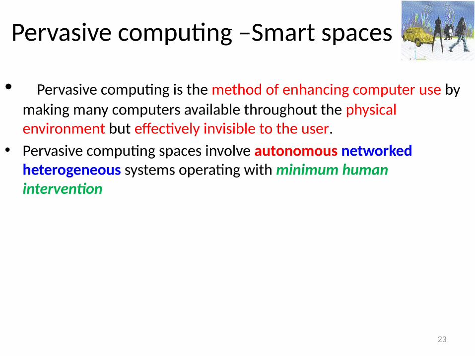
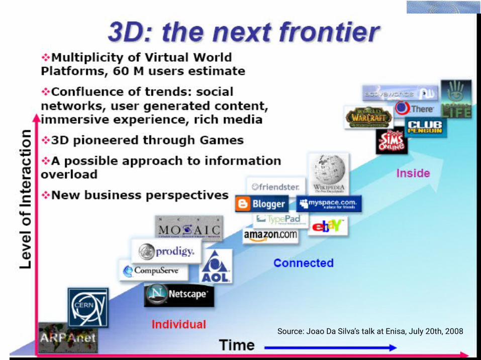
Pervasive computing –Smart spaces
• Pervasive computing is the method of enhancing computer use by making many computers available throughout the physical environment but effectively invisible to the user.
• Pervasive computing spaces involve autonomous networked heterogeneous systems operating with minimum human intervention
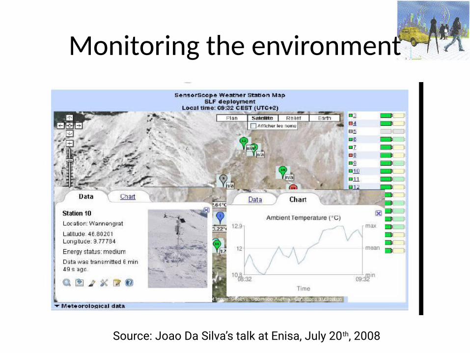
Monitoring the environment
Source: Joao Da Silva’s talk at Enisa, July 20th, 2008
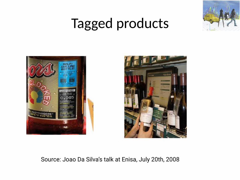
Tagged products
Source: Joao Da Silva’s talk at Enisa, July 20th, 2008
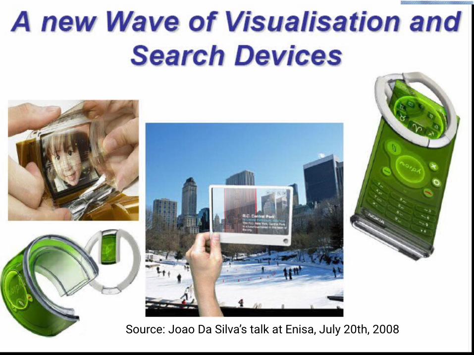
Source: Joao Da Silva’s talk at Enisa, July 20th, 2008
Source: Joao Da Silva’s talk at Enisa, July 20th, 2008
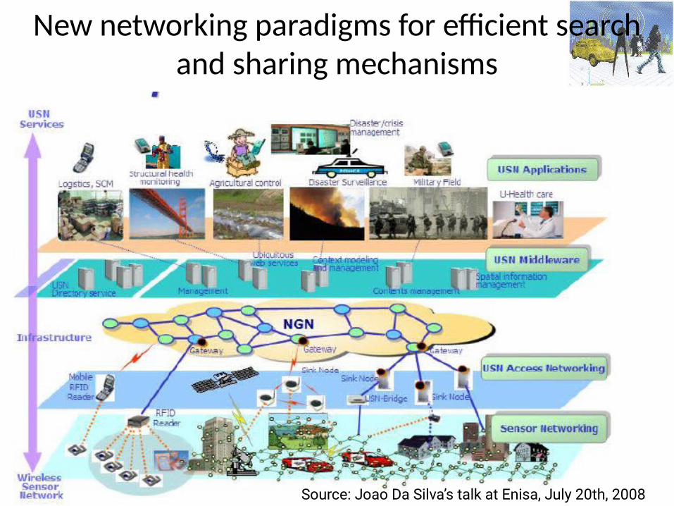
New networking paradigms for efficient search and sharing mechanisms
Source: Joao Da Silva’s talk at Enisa, July 20th, 2008

29
30
31
32
33
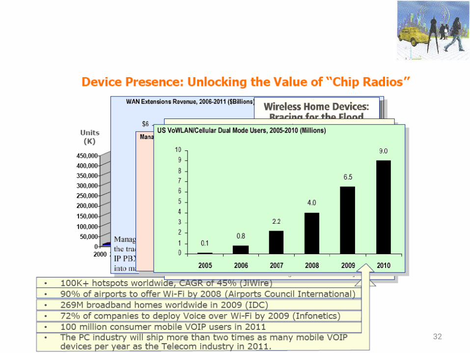
Fast Growth of Wireless Use
• Social networking (e.g., micro-blogging)• Multimedia downloads (e.g., Hulu, YouTube)• Gaming (Xbox Live)• 2D video conferencing • File sharing & collaboration• Cloud storage
Next generation applications• Immersive video conferencing• 3D Telemedicine• Virtual & Augmented reality• Assistive Technology
Rapid increase in the multimedia mobile Internet traffic
Fast Growth of Wireless Use (2/2)
• Video driving rapid growth in mobile Internet traffic• Expected to rise 66x by 2013 (Cisco Visual
Networking Index-Mobile Data traffic Forecast)
34
35
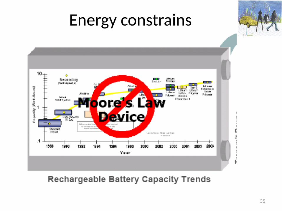
Energy constrains
36
Wireless Networks
• Are extremely complex • Have been used for many different purposes• Have their own distinct characteristics due to radio propagation characteristics & mobility wireless channels can be highly asymmetric & time varying
37
Lecture on Physical Layer
Prof. Maria PapadopouliUniversity of Crete
ICS-FORTHhttp://www.ics.forth.gr/mobile
Wireless Networks & Mobile Computing
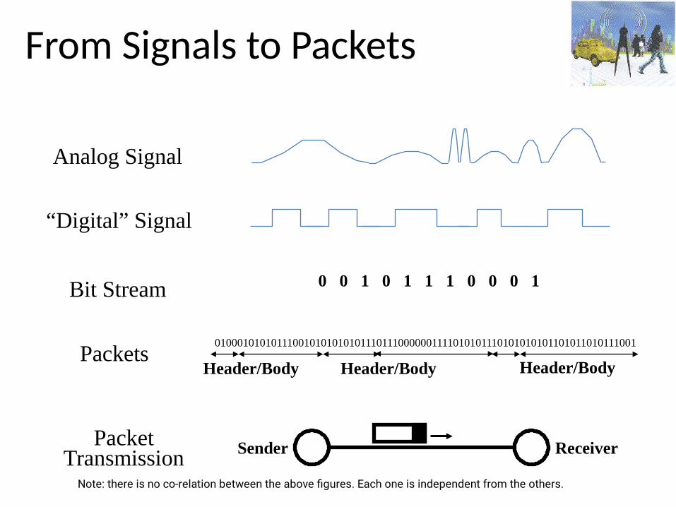
From Signals to Packets
Analog Signal
“Digital” Signal
Bit Stream 0 0 1 0 1 1 1 0 0 0 1
Packets0100010101011100101010101011101110000001111010101110101010101101011010111001
Header/Body Header/Body Header/Body
ReceiverSenderPacketTransmission
Note: there is no co-relation between the above figures. Each one is independent from the others.
Μοντέλο Τηλεπικοινωνιακών Συστημάτων
• Ο δίαυλος επικοινωνίας μπορεί να είναι μια γραμμή μεταφορά (π.χ. τηλεφωνία, Ethernet), μια οπτική ίνα ή απλά ο ελεύθερος χώρος (όπου το σήματα εκπέμπεται σας ηλεκτρομαγνητικό κύμα).
39
{από τη σκοπιά των σημάτων}
Μετάδοση Σήματος
• Κατά τη διάδοση του διαύλου το μεταδιδόμενο σήμα παραμορφώνεται λόγω μη γραμμικοτήτων και/ή ατελειών στην απόκριση συχνότητας του διαύλου
• Άλλες πηγές υποβάθμισης είναι ο θόρυβος και οι παρεμβολές που συλλέγονται από το σήματα κατά τη διάρκεια της μετάδοσης μέσω του διαύλου.
• Ο πομπός και ο δέκτης σχεδιάζονται ώστε να ελαχιστοποιούν τα αποτελέσματα του θορύβου και της παραμόρφωσης στη ποιότητα λήψης
• Αναδημιουργώντας το αρχικό σήμα, χρησιμοποιώντας τη διαδικασία της από-διαμόρφωσης (demodulation)
• Κύριοι πόροι (main resources): ισχύς εκπομπής (transmission power) & εύρος ζώνης (channel bandwidth)
40
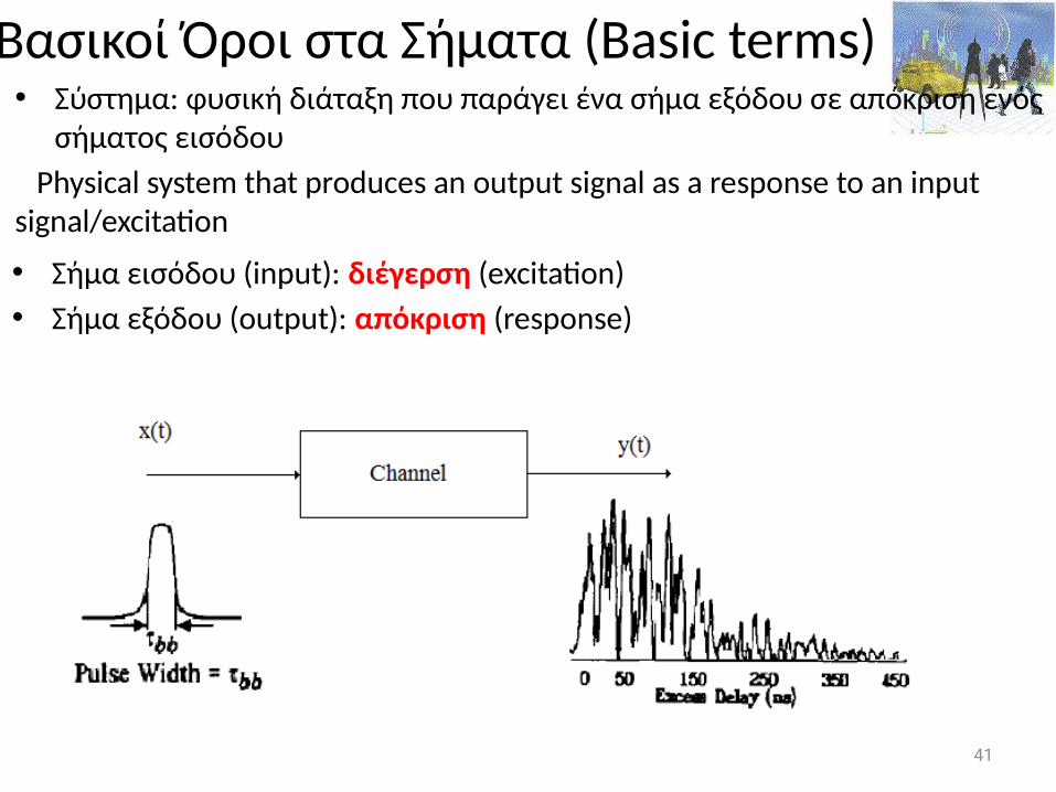
Βασικοί Όροι στα Σήματα (Basic terms)• Σύστημα: φυσική διάταξη που παράγει ένα σήμα εξόδου σε απόκριση ενός
σήματος εισόδου Physical system that produces an output signal as a response to an input signal/excitation
• Σήμα εισόδου (input): διέγερση (excitation)• Σήμα εξόδου (output): απόκριση (response)
41
Channel Model
• The received signal can be modeled by a magnitude and phase, which represent the signal attenuation and delay from sender antenna to receiver antenna,
given a certain frequency, where the communication takes place
• Devices use the transmission of a well-known training signal for the estimation of various parameters
42
Βασικοί Όροι στα Σήματα• Σε γραμμικά συστήματα ισχύει η αρχή της υπέρθεσης (superimposition): Η απόκριση ενός γραμμικού συστήματος σε ένα αριθμό διεγέρσεων τα οποία εφαρμόζονται ταυτόχρονα είναι ίση με το άθροισμα των αποκρίσεων του συστήματος, όταν κάθε μια από αυτές τις διεγέρσεις εφαρμόζεται ξεχωριστά• Φίλτρο: διάταξη επιλογής συχνότητας που χρησιμοποιείται για να
περιορίσει το φάσμα ενός σήματος σε μια ζώνη συχνοτήτων• Δίαυλος: μέσο μετάδοσης που συνδέει τον πομπό με τον δέκτη του
συστήματος επικοινωνίας• Περιγραφή στο πεδίο χρόνου ή συχνότητας
43
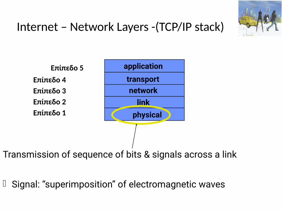
Internet – Network Layers -(TCP/IP stack)
Επίπεδο 5 Επίπεδο 4 Επίπεδο 3 Επίπεδο 2 Επίπεδο 1 physical
application
transportnetwork
link
Transmission of sequence of bits & signals across a link
Signal: “superimposition” of electromagnetic waves
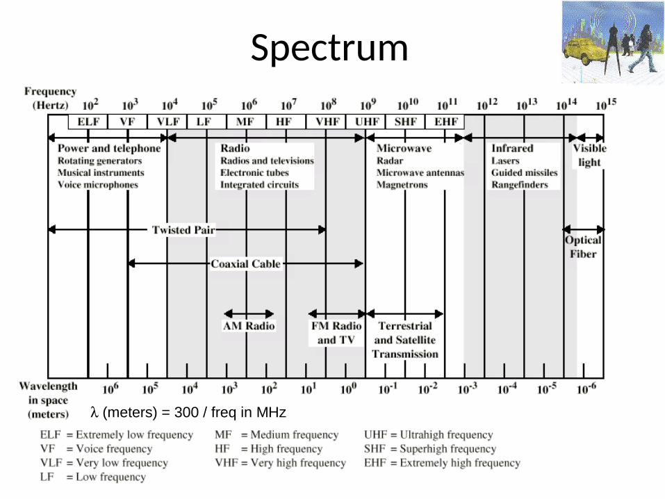
Spectrum
(meters) = 300 / freq in MHz
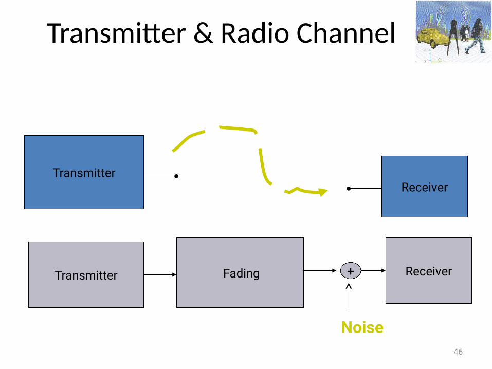
Transmitter & Radio Channel
46
TransmitterReceiver
Transmitter Fading +
Noise
Receiver
47
Electromagnetic Waveforms
• PropagateThey travel in the space from the sender to a receiver• Transfer energyThis energy can be used for data transmission
Two important properties
Φυσικό επίπεδο• Χειρίζεται τη μεταφορά της ακολουθίας των bits
ξεχωριστά κατά μήκος της ζεύξης
Τα bits στέλνονται διαδίδοντας ηλεκτρομαγνητικά κύματα κατά μήκους του φυσικού μέσου, πχ
– Επίγειο φάσμα ραδιοσυχνοτήτων– Δορυφορικό φάσμα ραδιοσυχνοτήτων
Η ζεύξη παραδίδει bits αφού πρώτα τα μετατρέψει σε σήματα τα οποία διαδίδονται μέσω ενός καναλιού
Σήμα καλείται η υπέρθεση ηλεκτρομαγνητικών κυμμάτων
1. Διαδίδονται Μετακινούνται δηλαδή απο το ένα μέρος στο άλλο, όπως από ένα πομπό σε ένα δέκτη
2. Περιέχουν ενέργεια η οποία μπορεί να χρησιμοποιηθεί για τη μεταφορά μηνυμάτων
Έχουν δύο σημαντικές ιδιότητες:
Ηλεκτρομαγνητικά κύματα
Ηλεκτρομαγνητικά κύματα (συνέχεια)
• Το Ηλεκτρομαγνητικό κύμα μπορεί να θεωρηθεί ως μια ροή φωτονίων
• Φωτόνιο: μικρή ριπή ηλεκτρομαγνητικής ενέργειας
Η ενέργεια μεταφέρεται από φωτόνια
Το φαινόμενο διάδοσης προκαλείται από τις αλληλεπιδράσεις ενός ταλαντούμενου ηλεκτρικού πεδίου και ενός ταλαντούμενου μαγνητικού πεδίου τα οποία ωθούν το ένα το άλλο στο κενό ή σε ένα άλλο μέσο διάδοσης
Βασικές αρχέςΈνα μεταβαλλόμενο μαγνητικό πεδίο παράγει ένα
μεταβαλλόμενο ηλεκτρικό πεδίο (Faraday)
Σε ένα ηλεκτρομαγνητικό κύμα, ένα μεταβαλλόμενο πεδίο επάγει ένα μεταβαλλόμενο ηλεκτρικό πεδίο, το οποίο με τη σειρά του δημιουργεί ένα μεταβαλλόμενο μαγνητικό πεδίο κ.ο.κ ... προκαλώντας έτσι τη διάδοση του κύματος (Maxwell)
Ηλεκτρομαγνητικό κύμα (συνέχεια)• Περιγράφεται από τη συχνότητα: αριθμός
ταλαντώσεων των ηλεκτρικών και μαγνητικών πεδίων στην μονάδα του χρόνου
1Hertz αντιστοιχεί σε μια πλήρη ταλάντωση ανά δευτερόλεπτο
και το μήκος κύματος: λόγος ταχύτητας διάδοσης προς συχνότητα
Τα δίκτυα επικοινωνιών μεταδίδουν πληροφορία μέσω ηλεκτρομαγνητικών κυμάτων
Βασικά στοιχεία ηλεκτρικού ρεύματος• Η ροή φορτίου (flow charge) ονομάζεται ηλεκτρικό ρεύμα (electric
current) και είναι ο ρυθμός με τον οποίο τα ηλεκτρικά φορτία διέρχονται διαμέσου ενός αγωγού (conductive material)
• Τα φορτισμένα σωματίδια μπορούν να είναι είτε θετικά είτε αρνητικά• Για τη ροή φορτίου, απαιτείται μία ώθηση (μία δύναμη) η οποία
παρέχεται από την τάση ή διαφορά δυναμικού (potential difference)• Το φορτίο (charge) κινείται από το υψηλό δυναμικό (περιοχή υψηλής
δυναμικής ενέργειας) προς το χαμηλό δυναμικό (περιοχή χαμηλής δυναμικής ενέργειας
Αν υπάρχει διαφορά δυναμικού μεταξύ δύο περιοχών και εμείς τις συνδέσουμε (αγώγιμα), θα υπάρξει ροή φορτίου
Το φορτίο συνεχίζει να κινείται μέχρι η δύναμη που ασκείται πάνω του να μειωθεί σε κάποια ελάχιστη τιμή ή έως ότου το δυναμικό εξισωθεί
Βασικά στοιχεία ηλεκτρικής τάσης
• Η τάση θα έπρεπε να καλείται ορθότερα «διαφορά δυναμικού»• Είναι στην πραγματικότητα η ηλεκτρεγερτική δύναμη (emf) (η κινητήριος
δύναμη των ηλεκτρονίων στον ηλεκτρισμό) Η διαφορά δυναμικού είναι υπεύθυνη για την άπωση και την έλξη των
ηλεκτρονίων ή για το ηλεκτρικό ρεύμα διαμέσου ενός κυκλώματος
• Μία κινητήριος δύναμη ηλεκτρονίων επίσης υπάρχει μεταξύ δύο αντικειμένων όποτε υπάρχει μία διαφορά στον αριθμό των ελεύθερων ηλεκτρονίων ανά μονάδα όγκου του αντικειμένου.
• Όταν δύο αντικείμενα, που είναι αρνητικά φορτισμένα, συνδεθούν αγώγιμα μεταξύ τους, το ηλεκτρικό ρεύμα θα έχει φορά από το περισσότερο αρνητικά φορτισμένο αντικείμενο προς το λιγότερο αρνητικά φορτισμένο
• Ροή ηλεκτρικού ρεύματος θα υπάρξει επίσης από ένα λιγότερο θετικά φορτισμένο αντικείμενο προς ένα περισσότερο θετικά φορτισμένο αντικείμενο, εφόσον τα δύο αντικείμενα συνδεθούν αγώγιμα μεταξύ τους
Φυσικό επίπεδο• Χειρίζεται τη μεταφορά της ακολουθίας των bits ξεχωριστά κατά
μήκος της ζεύξης
Τα bits στέλνονται διαδίδοντας ηλεκτρομαγνητικά κύματα ή οπτικούς παλμούς κατα μήκος του φυσικού μέσου– Συνεστραμμένο χάλκινο καλώδιο (twisted pair copper wire)– Ομοαξονικό καλώδιο (coaxial cable)– Επίγειο φάσμα ραδιοσυχνοτήτων– Δορυφορικό φάσμα ραδιοσυχνοτήτων
Η ζεύξη παραδίδει bits αφού πρώτα τα μετατρέψει σε σήματα τα οποία διαδίδονται μέσω ενός καναλιού
Σήμα καλείται η υπέρθεση ηλεκτρομαγνητικών κυμάτων

1. Διαδίδονται Μετακινούνται δηλαδή απο το ένα μέρος στο άλλο, όπως από ένα πομπό σε ένα δέκτη
2. Περιέχουν ενέργεια η οποία μπορεί να χρησιμοποιηθεί για τη μεταφορά μηνυμάτων
Έχουν δύο σημαντικές ιδιότητες:
Ηλεκτρομαγνητικά κύματα
Ηλεκτρομαγνητικά κύματα (συνέχεια)
• Το Ηλεκτρομαγνητικό κύμα μπορεί να θεωρηθεί ως μια ροή φωτονίων
• Φωτόνιο: μικρή ριπή ηλεκτρομαγνητικής ενέργειας Η ενέργεια μεταφέρεται από φωτόνια
Το φαινόμενο διάδοσης προκαλείται από τις αλληλεπιδράσεις ενός ταλαντούμενου ηλεκτρικού πεδίου και ενός ταλαντούμενου μαγνητικού πεδίου τα οποία ωθούν το ένα το άλλο στο κενό ή σε ένα άλλο μέσο διάδοσης

Βασικές αρχέςΈνα μεταβαλλόμενο μαγνητικό πεδίο παράγει ένα
μεταβαλλόμενο ηλεκτρικό πεδίο (Faraday)
Σε ένα ηλεκτρομαγνητικό κύμα, ένα μεταβαλλόμενο πεδίο επάγει ένα μεταβαλλόμενο ηλεκτρικό πεδίο, το οποίο με τη σειρά του δημιουργεί ένα μεταβαλλόμενο μαγνητικό πεδίο κ.ο.κ ... προκαλώντας έτσι τη διάδοση του κύματος (Maxwell)
Ηλεκτρομαγνητικό κύμα (συνέχεια)
• Περιγράφεται από τη συχνότητα: αριθμός ταλαντώσεων των ηλεκτρικών και μαγνητικών πεδίων στην μονάδα του χρόνου
1Hertz αντιστοιχεί σε μια πλήρη ταλάντωση ανά δευτερόλεπτο
και το μήκος κύματος: λόγος ταχύτητας διάδοσης προς συχνότητα
Τα δίκτυα επικοινωνιών μεταδίδουν πληροφορία μέσω ηλεκτρομαγνητικών κυμάτων
Τα ηλεκτρόνια στα σύρματα ή στο καλώδιο μίας γραμμής χαλκούαλληλοεπιδρούν με το ηλεκτρομαγνητικό κύμα και το οδηγούν
Βασικά στοιχεία ηλεκτρικού ρεύματος
• Η ροή φορτίου ονομάζεται ηλεκτρικό ρεύμα και είναι ο ρυθμός με τον οποίο τα ηλεκτρικά φορτία διέρχονται διαμέσου ενός αγωγού
• Τα φορτισμένα σωματίδια μπορούν να είναι είτε θετικά είτε αρνητικά• Για τη ροή φορτίου, απαιτείται μία ώθηση (μία δύναμη) η οποία
παρέχεται από την τάση ή διαφορά δυναμικού• Το φορτίο κινείται από το υψηλό δυναμικό (περιοχή υψηλής δυναμικής
ενέργειας) προς το χαμηλό δυναμικό (περιοχή χαμηλής δυναμικής ενέργειας
Αν υπάρχει διαφορά δυναμικού μεταξύ δύο περιοχών και εμείς τις συνδέσουμε (αγώγιμα), θα υπάρξει ροή φορτίου
Το φορτίο συνεχίζει να κινείται μέχρι η δύναμη που ασκείται πάνω του να μειωθεί σε κάποια ελάχιστη τιμή ή έως ότου το δυναμικό εξισωθεί
Βασικά στοιχεία ηλεκτρικής τάσης
• Η τάση θα έπρεπε να καλείται ορθότερα «διαφορά δυναμικού»
• Είναι στην πραγματικότητα η ηλεκτρεγερτική δύναμη (emf) (η κινητήριος δύναμη των ηλεκτρονίων στον ηλεκτρισμό) Η διαφορά δυναμικού είναι υπεύθυνη για την
άπωση και την έλξη των ηλεκτρονίων ή για το ηλεκτρικό ρεύμα διαμέσου ενός κυκλώματος
Βασικά στοιχεία ηλεκτρικής τάσης• Μία κινητήριος δύναμη ηλεκτρονίων επίσης υπάρχει μεταξύ δύο
αντικειμένων όποτε υπάρχει μία διαφορά στον αριθμό των ελεύθερων ηλεκτρονίων ανά μονάδα όγκου του αντικειμένου.
• Όταν δύο αντικείμενα, που είναι αρνητικά φορτισμένα, συνδεθούν
αγώγιμα μεταξύ τους, το ηλεκτρικό ρεύμα θα έχει φορά από το περισσότερο αρνητικά φορτισμένο αντικείμενο προς το λιγότερο αρνητικά φορτισμένο
• Ροή ηλεκτρικού ρεύματος θα υπάρξει επίσης από ένα λιγότερο θετικά φορτισμένο αντικείμενο προς ένα περισσότερο θετικά φορτισμένο αντικείμενο, εφόσον τα δύο αντικείμενα συνδεθούν αγώγιμα μεταξύ τους

Βασικά στοιχεία ηλεκτρικής τάσης (συνέχεια)
Το ηλεκτροστατικό πεδίο, δηλαδή η τάση των ηλεκτρονίων να
προσπαθούν να φτάσουν ένα θετικό φορτίο ή να προέρχονται από πιο υψηλό αρνητικό φορτίο είναι η κινητήριος δύναμη των ηλεκτρονίων ή αλλιώς τάση
• Εκφράζεται σε μονάδες που ονομάζονται volts, σύντμηση του voltage
Ως ένα volt ορίζεται η πίεση που απαιτείται για τη διέλευση ρεύματος ενός ampere διαμέσου μίας αντίστασης ενός ohm
Έννοιες πεδίου χρόνου: Αναλογικά & ψηφιακά σήματα
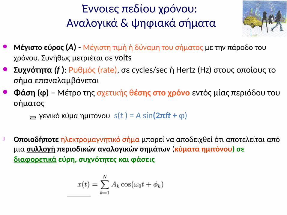
Μέγιστο εύρος (A) - Μέγιστη τιμή ή δύναμη του σήματος με την πάροδο του χρόνου. Συνήθως μετριέται σε volts
Συχνότητα (f ): Ρυθμός (rate), σε cycles/sec ή Hertz (Hz) στους οποίους το σήμα επαναλαμβάνεται
Φάση (φ) – Μέτρο της σχετικής θέσης στο χρόνο εντός μίας περιόδου του σήματος
γενικό κύμα ημιτόνου s(t ) = A sin(2πft + φ)
Οποιοδήποτε ηλεκτρομαγνητικό σήμα μπορεί να αποδειχθεί ότι αποτελείται από μια συλλογή περιοδικών αναλογικών σημάτων (κύματα ημιτόνου) σε διαφορετικά εύρη, συχνότητες και φάσεις
Βασικά στοιχεία ηλεκτρικής τάσης (συνέχεια)
Το ηλεκτροστατικό πεδίο, δηλαδή η τάση των ηλεκτρονίων να
προσπαθούν να φτάσουν ένα θετικό φορτίο ή να προέρχονται από πιο υψηλό αρνητικό φορτίο είναι η κινητήριος δύναμη των ηλεκτρονίων ή αλλιώς τάση
• Εκφράζεται σε μονάδες που ονομάζονται volts, σύντμηση του voltage
Ως ένα volt ορίζεται η πίεση που απαιτείται για τη διέλευση ρεύματος ενός ampere διαμέσου μίας αντίστασης ενός ohm

Έννοιες πεδίου χρόνου: Αναλογικά & ψηφιακά σήματα
Μέγιστο εύρος (A) - Μέγιστη τιμή ή δύναμη του σήματος με την πάροδο του χρόνου. Συνήθως μετριέται σε volts
Συχνότητα (f ): Ρυθμός (rate), σε cycles/sec ή Hertz (Hz) στους οποίους το σήμα επαναλαμβάνεται
Φάση (φ) – Μέτρο της σχετικής θέσης στο χρόνο εντός μίας περιόδου του σήματος
γενικό κύμα ημιτόνου s(t ) = A sin(2πft + φ)
Οποιοδήποτε ηλεκτρομαγνητικό σήμα μπορεί να αποδειχθεί ότι αποτελείται από μια συλλογή περιοδικών αναλογικών σημάτων (κύματα ημιτόνου) σε διαφορετικά εύρη, συχνότητες και φάσεις
Antenna (1/2)
67
• Made of conducting material• Radio waves hitting an antenna cause electrons to flow in the
conductor and create current• Likewise, applying a current to an antenna creates an electric field
around the antenna• As the current of the antenna changes, so does the electric field• A changing electric field causes a magnetic field, and the wave is off …
Antenna (2/2)
68
• Antenna gain the extent to which it enhances the signal in its preferred direction
• Isotropic antenna radiates power with unit gain uniformly in all directions
• Measured in dBi: decibels relative to an isotropic radiator
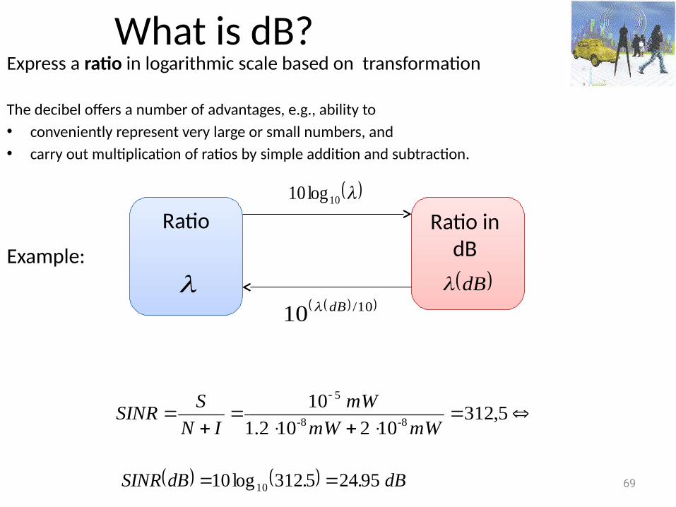
What is dB?Express a ratio in logarithmic scale based on transformation
The decibel offers a number of advantages, e.g., ability to • conveniently represent very large or small numbers, and • carry out multiplication of ratios by simple addition and subtraction.
Example:
69
Ratio Ratio in dB
10log10
10/10 dB
5,312102101.2
108-8-
5
mWmW
mW
IN
SSINR
dB
dB..dBSINR 95245312log10 10
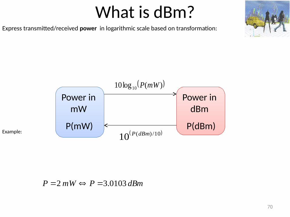
What is dBm?Express transmitted/received power in logarithmic scale based on transformation:
Example:
70
P(mW)
Power in mW
Power in dBm
P(dBm)
)(log10 10 mWP
10/)(10 dBmP
dBmPmWP 0103.3 2
71
dBm (sometimes dBmW) is an abbreviation for the power ratio in decibels (dB) of the measured power referenced to one milliwatt (mW).
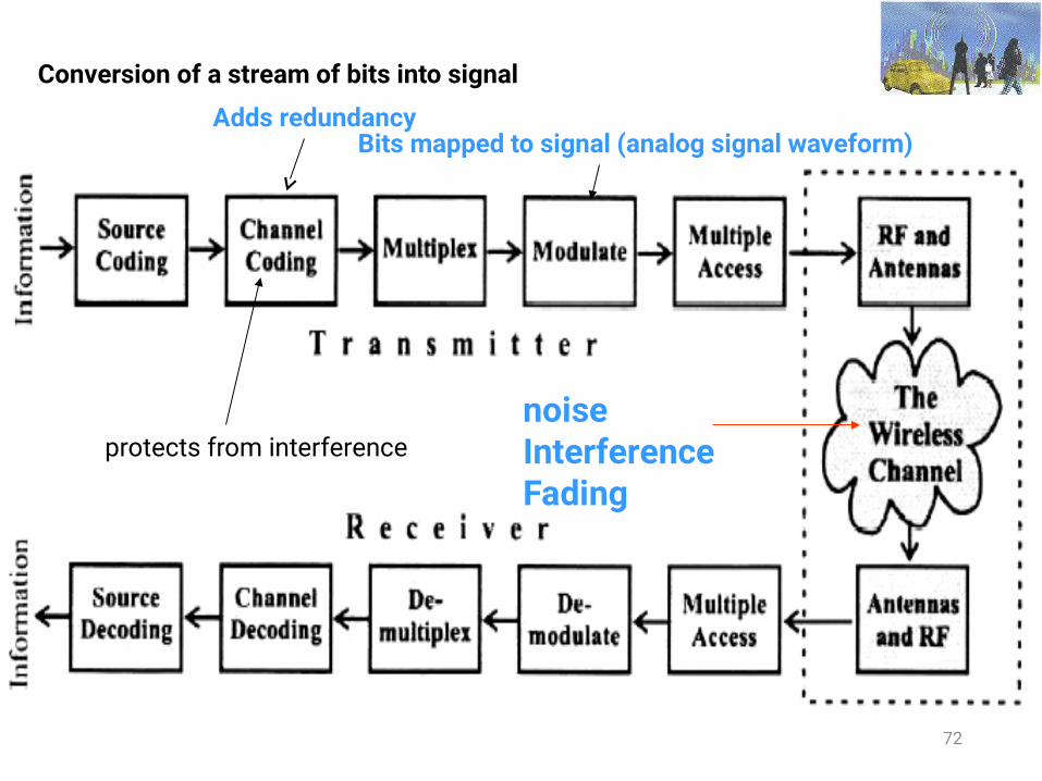
Conversion of a stream of bits into signal
72
Adds redundancyBits mapped to signal (analog signal waveform)
noiseInterferenceFading
protects from interference
Conversion of a stream of bits into signal
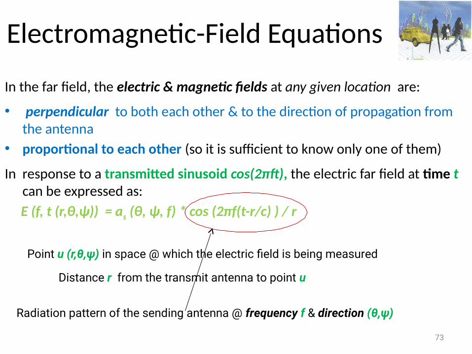
Electromagnetic-Field Equations
In the far field, the electric & magnetic fields at any given location are:
• perpendicular to both each other & to the direction of propagation from the antenna
• proportional to each other (so it is sufficient to know only one of them)
In response to a transmitted sinusoid cos(2πft), the electric far field at time t can be expressed as:
E (f, t (r,θ,ψ)) = as (θ, ψ, f) * cos (2πf(t-r/c) ) / r
73
Point u (r,θ,ψ) in space @ which the electric field is being measured
Distance r from the transmit antenna to point u
Radiation pattern of the sending antenna @ frequency f & direction (θ,ψ)
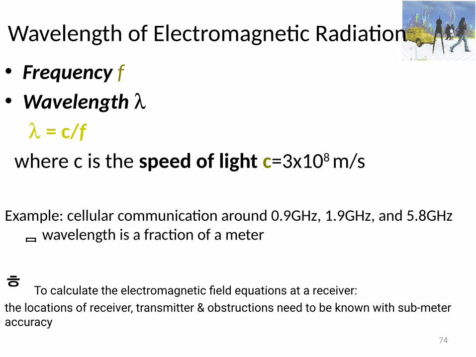
Wavelength of Electromagnetic Radiation
• Frequency f• Wavelength = c/f where c is the speed of light c=3x10⁸ m/s
Example: cellular communication around 0.9GHz, 1.9GHz, and 5.8GHz wavelength is a fraction of a meter
74
To calculate the electromagnetic field equations at a receiver:the locations of receiver, transmitter & obstructions need to be known with sub-meter accuracy
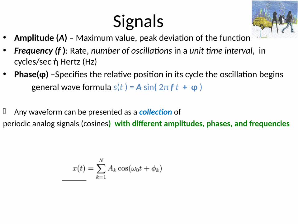
Signals • Amplitude (A) – Maximum value, peak deviation of the function• Frequency (f ): Rate, number of oscillations in a unit time interval, in
cycles/sec ή Hertz (Hz)• Phase(φ) –Specifies the relative position in its cycle the oscillation begins general wave formula s(t ) = A sin( 2π f t + φ )
Any waveform can be presented as a collection of periodic analog signals (cosines) with different amplitudes, phases, and frequencies
Χρήση των ημιτονοειδή συναρτήσεων
Χρησιμοποιούμε ημιτονοειδής συναρτήσεις λόγω της δυνατότητας επιλογής της κεντρικής συχνότητας που μπορούμε να μεταδώσουμε, και λόγω των φασματικών χαρακτηριστικών που έχει αυτή η συνάρτηση.
Στο πεδίο της συχνότητας μια ημιτονοειδής συνάρτηση περιγράφεται από ένα Dirac. Αλλάζοντας τη διάρκεια συμβόλου (δηλ. πόσο χρόνο χρειάζεται να μεταδώσουμε ένα σύμβολο), μπορούμε να αλλάξουμε το bandwidth.
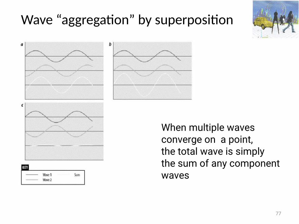
Wave “aggregation” by superposition
77
When multiple waves converge on a point, the total wave is simply the sum of any component waves
78
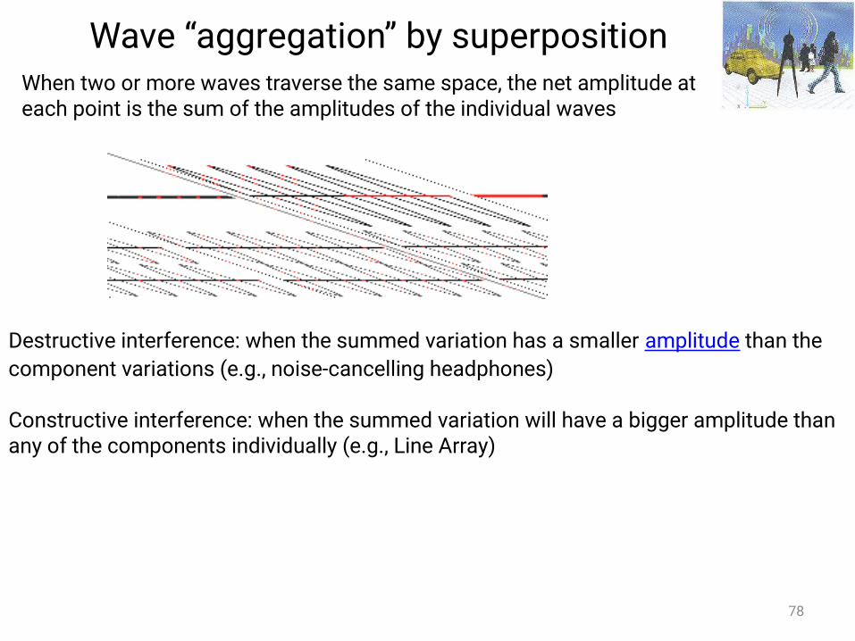
When two or more waves traverse the same space, the net amplitude at each point is the sum of the amplitudes of the individual waves
Destructive interference: when the summed variation has a smaller amplitude than the component variations (e.g., noise-cancelling headphones)
Constructive interference: when the summed variation will have a bigger amplitude than any of the components individually (e.g., Line Array)
Wave “aggregation” by superposition
79
Wireless channels• Operate through electromagnetic radiation from the transmitter to
the receiver• In principle, one could solve the electromagnetic field equations, in
conjunction with the transmitted signal to find the electromagnetic field impinging on the receiver antenna
This would have to be done taking into account the obstructions caused by ground, buildings, vehicles, etc in the vicinity of this electromagnetic wave
• Multiple copies of the signal could be propagated and reach the receiver (Το σήμα φτάνει από διαφορετικές κατευθύνσεις, με διαφορετικές καθυστερήσεις, ακολουθώντας διαφορετικές διαδρομές)
• Το σήμα που λαμβάνεται στον δέκτη αποτελείται δυνητικά από έναν αριθμό σημάτων με διαφορετική ένταση, φάση και γωνία άφιξης
Fundamentals• Impairments• Radio Propagation• Wireless channel model• Digital modulation and detection techniques• Error control techniques
80
Types of Impairments
– Noise: thermal (electronics at the receiver, λόγω της τυχαίας κίνησης των
ηλεκτρονίων σε έναν αγωγό), humanΕξωτερικές πηγές (πχ ατμοσφαιρικός, γαλαξιακός, βιομηχανικός) & εσωτερικές πηγές (πχ στιγμιαίων διακυμάνσεων του ρεύματος ή τα τάσης στα ηλεκτρικά κυκλώματα) θορύβου
– Radio frequency signal path loss– Fading at low rates– Inter-Symbol interference (ISI)– Shadow fading– Co-channel interference– Adjacent channel interference
81
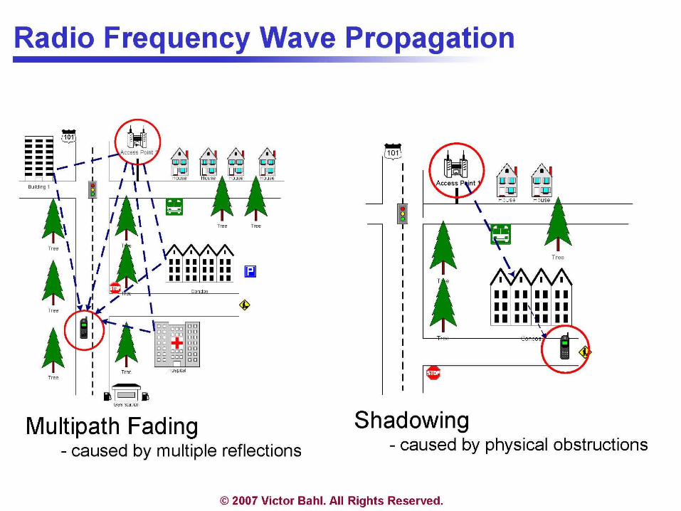
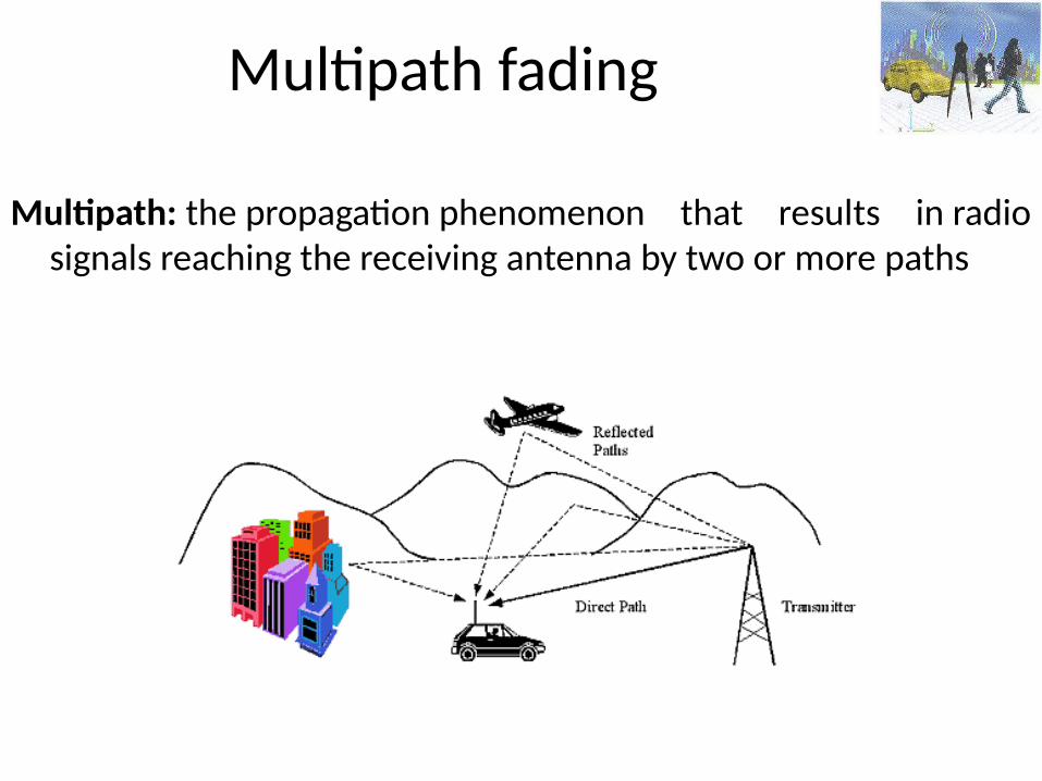
Multipath fading
Multipath: the propagation phenomenon that results in radio signals reaching the receiving antenna by two or more paths
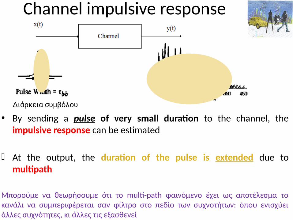
Channel impulsive response
• By sending a pulse of very small duration to the channel, the impulsive response can be estimated
At the output, the duration of the pulse is extended due to multipath
Μπορούμε να θεωρήσουμε ότι το multi-path φαινόμενο έχει ως αποτέλεσμα το κανάλι να συμπεριφέρεται σαν φίλτρο στο πεδίο των συχνοτήτων: όπου ενισχύει άλλες συχνότητες, κι άλλες τις εξασθενεί
Διάρκεια συμβόλου
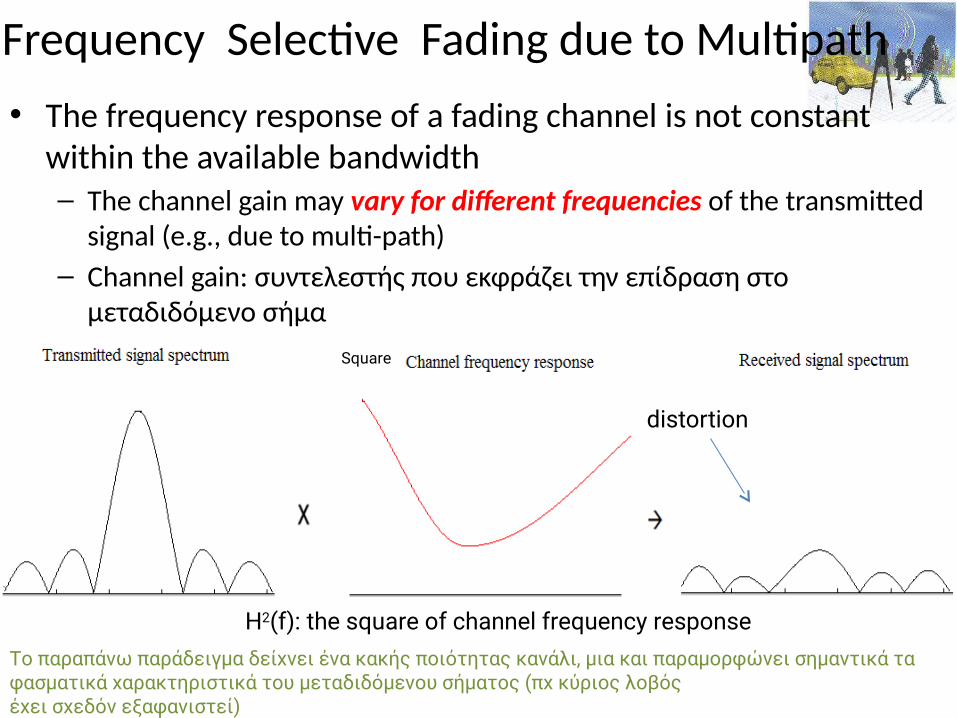
Frequency Selective Fading due to Multipath• The frequency response of a fading channel is not constant
within the available bandwidth– The channel gain may vary for different frequencies of the transmitted
signal (e.g., due to multi-path)– Channel gain: συντελεστής που εκφράζει την επίδραση στο
μεταδιδόμενο σήμα
H2(f): the square of channel frequency response
Square
distortion
Το παραπάνω παράδειγμα δείχνει ένα κακής ποιότητας κανάλι, μια και παραμορφώνει σημαντικά τα φασματικά χαρακτηριστικά του μεταδιδόμενου σήματος (πχ κύριος λοβόςέχει σχεδόν εξαφανιστεί)
Main issues in wireless communications
86
Fading: time variation of signal strength due to:• Small-scale effect of multipath fading
• Larger-scale effects, such as • Path loss via distance attenuation• Shadowing via obstacles
InterferenceUnlike the wired world, where transmitter-receiver pair can often be though of as an isolated point-to-point link, wireless users communicate over the air & there is significant interference between them
Types of fading
• Large-scale fading, due to path loss of signal as function of distance & shadowing by large objects (hills, buildings) This occurs as wireless devices move through a distance of the
order of cell size and is typically frequency independent– large transmitter-receiver distances
• Small-scale fading, due to constructive & destructive interference of multiple signal paths between transmitter & receiver This occurs at the spatial scale of the order of the carrier
wavelength and is frequency dependent rapid fluctuations of the received signal strength over very short
travel distances or short time durations (order of seconds)87
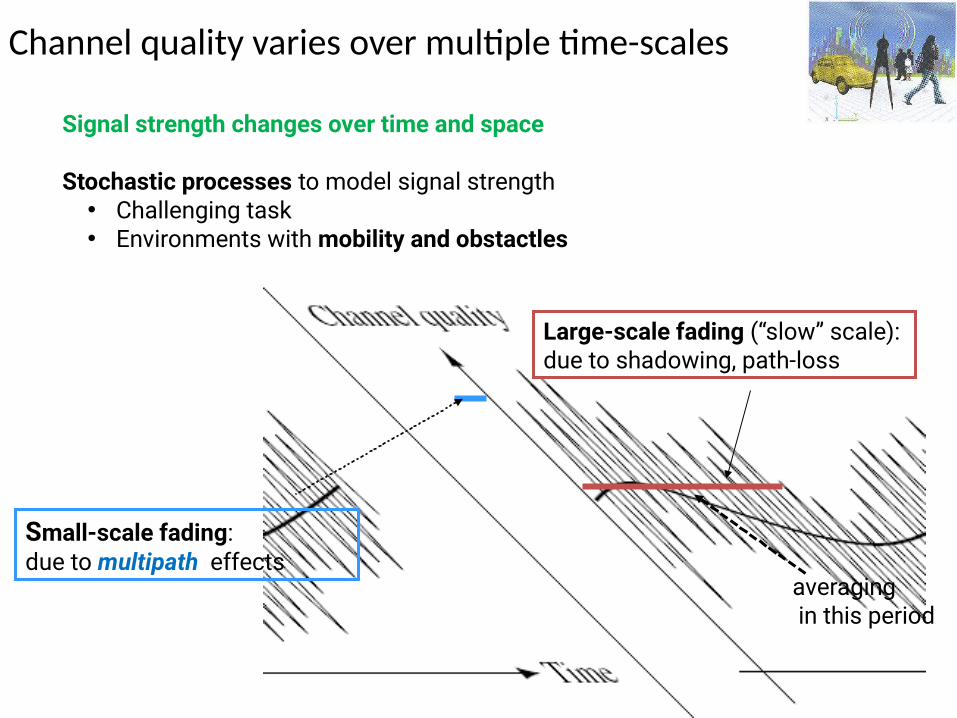
Channel quality varies over multiple time-scales
88
Small-scale fading: due to multipath effects
Large-scale fading (“slow” scale): due to shadowing, path-loss
Signal strength changes over time and space
Stochastic processes to model signal strength• Challenging task• Environments with mobility and obstactles
averaging in this period
Large, medium & small-scale fading
• Large-scale fading: average signal power attenuation/path loss due to motion over large areas.
• Medium-scale fading: local variation in the average signal power around mean average power due to shadowing by local obstructions.
• Small-scale: large variation in the signal power due to small changes in the distance between transmitter & receiver
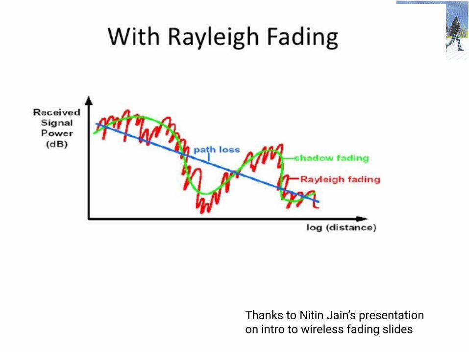
Also called Rayleigh fading when no LOS availabe. It is called Rayleigh due to the fact that various multipaths at the receiver with random amplitude & delay add up together to render rayleigh PDF for total signal
89
Fading: fluctuation in the received signal power
90
Thanks to Nitin Jain’s presentation on intro to wireless fading slides
Multipath fading
Fluctuation in the received power due to• Variations in the received signal amplitude• Variation in the signal phase• Variations in the received signal angle of arrival (different paths
travelling different distances may have different phases & angle of arrival)
There is signal superimposition …
91
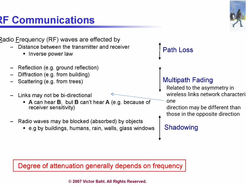
Related to the asymmetry in wireless links network characteristics in one direction may be different than those in the opposite direction
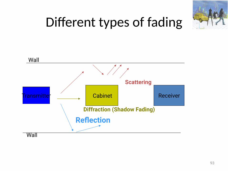
Different types of fading
93
Wall
Wall
Transmitter Cabinet
ReflectionDiffraction (Shadow Fading)
Scattering
Receiver
94
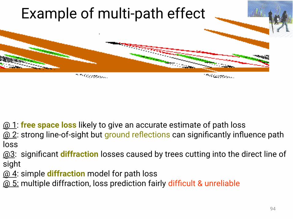
@ 1: free space loss likely to give an accurate estimate of path loss@ 2: strong line-of-sight but ground reflections can significantly influence path loss@3: significant diffraction losses caused by trees cutting into the direct line of sight@ 4: simple diffraction model for path loss @ 5: multiple diffraction, loss prediction fairly difficult & unreliable
Example of multi-path effect
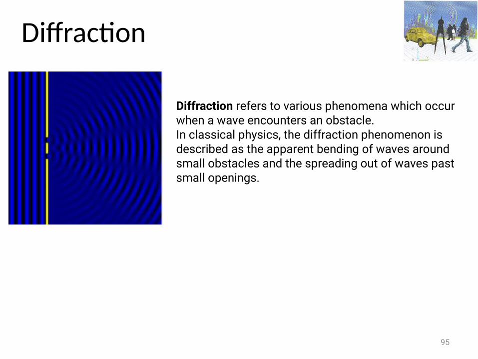
Diffraction
95
Diffraction refers to various phenomena which occur when a wave encounters an obstacle. In classical physics, the diffraction phenomenon is described as the apparent bending of waves around small obstacles and the spreading out of waves past small openings.
Shadow Fading
• Obstacles and their absorption behavior• Shadowing differs from multi-path fading
Duration of shadow fade lasts for multiple seconds or minutes a much slower time-scale compared to multi-path fading
96
Reflection
• Wave impinges upon a large object when compared to the wavelength of the propagating wave
• Reflections occur from the surface of– The earth– Buildings– Walls
97
Scattering
• Another type of reflection
• Can occur in the atmosphere or in reflections from very rough objects
• Very large number of individual paths Received waveform is better modeled as an integral over paths with infinitesimally small differences in their lengths
rather than as a sum
98
Multi-path Delay Spread
• Time between the arrival of the first wavefront & last multi-path echo,
counting only the paths with significant energy• Longer delay spreads require more conservative coding • 802.11b networks can handle delay spreads of < 500 ns• Performance is much better when the delay spread is low• When delay spread is large cards may reduce transmission rate
99
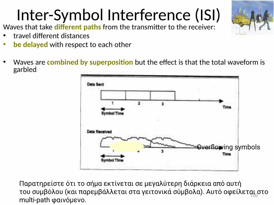
Inter-Symbol Interference (ISI)Waves that take different paths from the transmitter to the receiver:• travel different distances• be delayed with respect to each other
• Waves are combined by superposition but the effect is that the total waveform is garbled
100
Overflowing symbols
Παρατηρείστε ότι το σήμα εκτίνεται σε μεγαλύτερη διάρκεια από αυτή του συμβόλου (και παρεμβάλλεται στα γειτονικά σύμβολα). Αυτό οφείλεται στοmulti-path φαινόμενο.
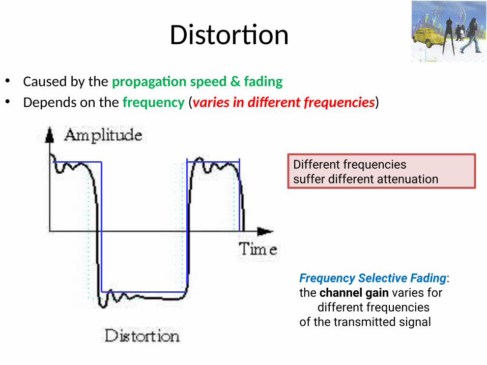
Distortion• Caused by the propagation speed & fading • Depends on the frequency (varies in different frequencies)
Frequency Selective Fading:the channel gain varies for different frequencies of the transmitted signal
Different frequenciessuffer different attenuation
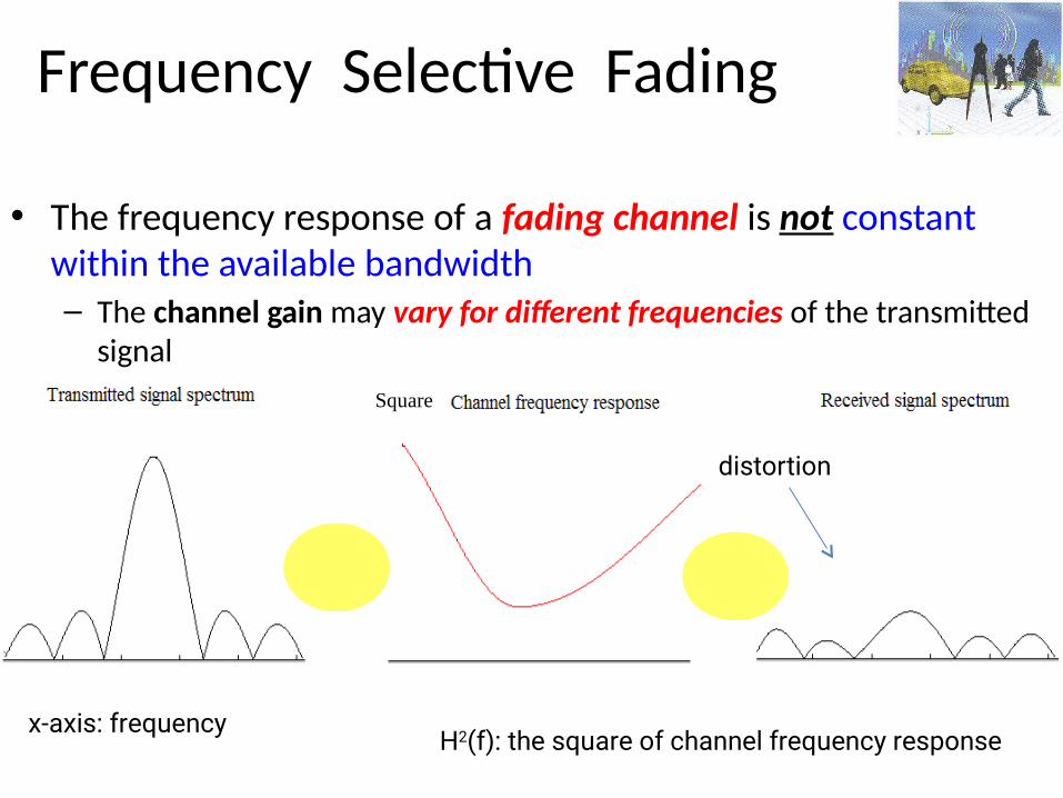
Frequency Selective Fading
• The frequency response of a fading channel is not constant within the available bandwidth– The channel gain may vary for different frequencies of the transmitted
signal
H2(f): the square of channel frequency response
Square
distortion
x-axis: frequency
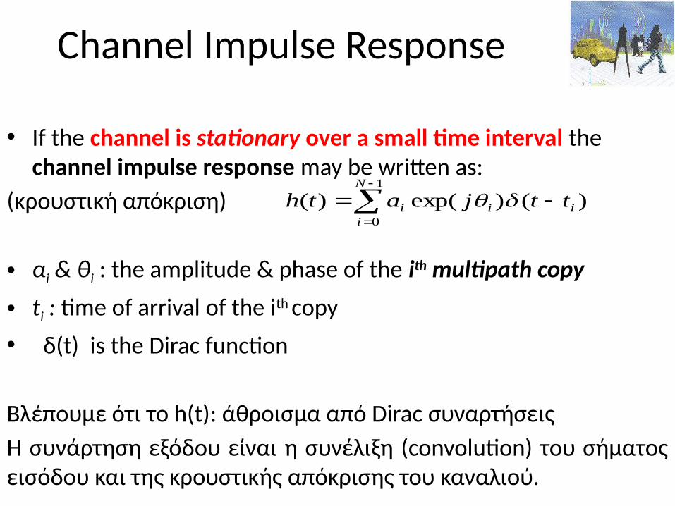
Channel Impulse Response
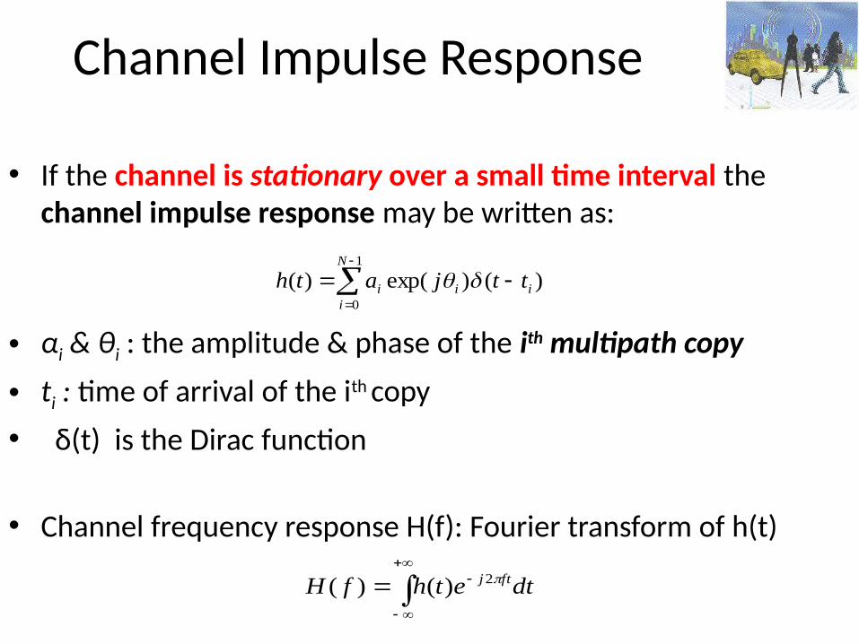
• If the channel is stationary over a small time interval the channel impulse response may be written as:
(κρουστική απόκριση)
• αi & θi : the amplitude & phase of the ith multipath copy
• ti : time of arrival of the ith copy• δ(t) is the Dirac function
Βλέπουμε ότι το h(t): άθροισμα από Dirac συναρτήσειςΗ συνάρτηση εξόδου είναι η συνέλιξη (convolution) του σήματος εισόδου και της κρουστικής απόκρισης του καναλιού.
1
0
)()exp()(N
iiii ttjath
Channel Impulse Response
• If the channel is stationary over a small time interval the channel impulse response may be written as:
• αi & θi : the amplitude & phase of the ith multipath copy
• ti : time of arrival of the ith copy• δ(t) is the Dirac function
• Channel frequency response H(f): Fourier transform of h(t)
1
0
)()exp()(N
iiii ttjath
dtethfH ftj 2)()(
Power Spectral Density of the Received Signal
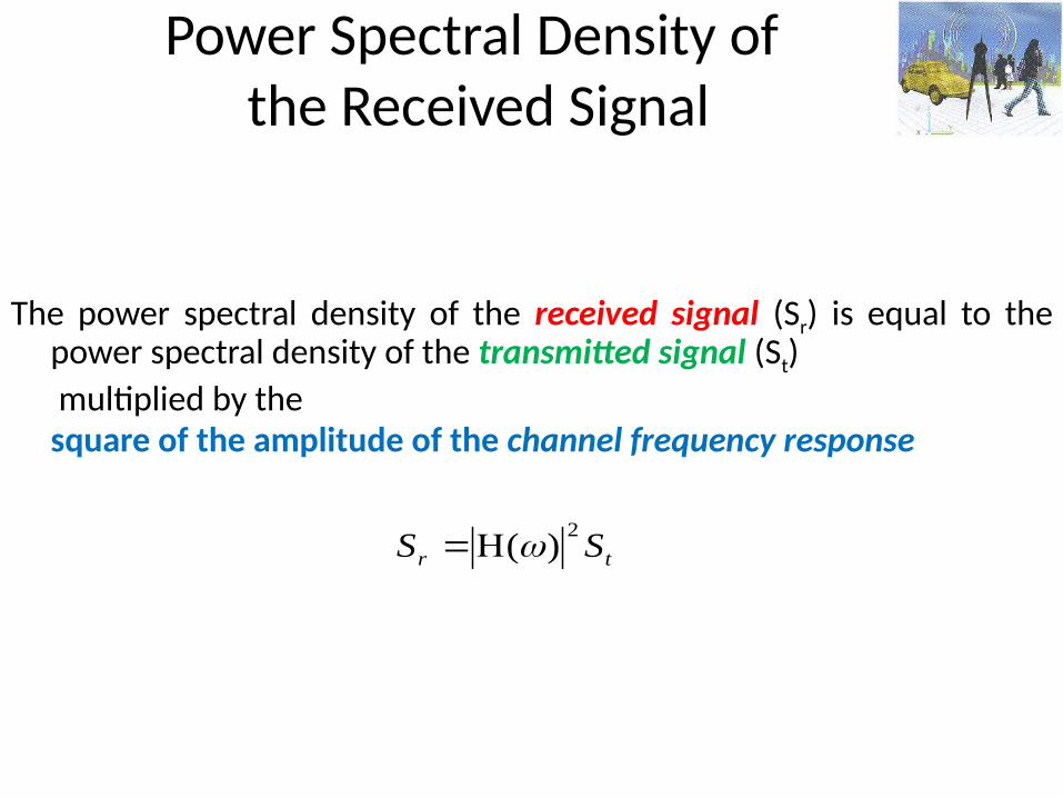
The power spectral density of the received signal (Sr) is equal to the power spectral density of the transmitted signal (St)
multiplied by the square of the amplitude of the channel frequency response
tr SS2
)(
Doppler Effect
• The Doppler effect is observed whenever the source of waves is moving with respect to an observer
• It is the effect produced by a moving source of waves in which there is an apparent upward (downward) shift in frequency for observers towards whom the source is approaching (receding), respectively
106
107
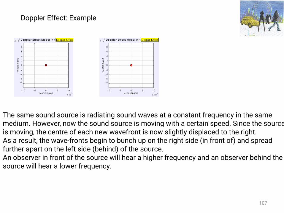
Doppler Effect: Example
The same sound source is radiating sound waves at a constant frequency in the same medium. However, now the sound source is moving with a certain speed. Since the source is moving, the centre of each new wavefront is now slightly displaced to the right. As a result, the wave-fronts begin to bunch up on the right side (in front of) and spread further apart on the left side (behind) of the source. An observer in front of the source will hear a higher frequency and an observer behind the source will hear a lower frequency.
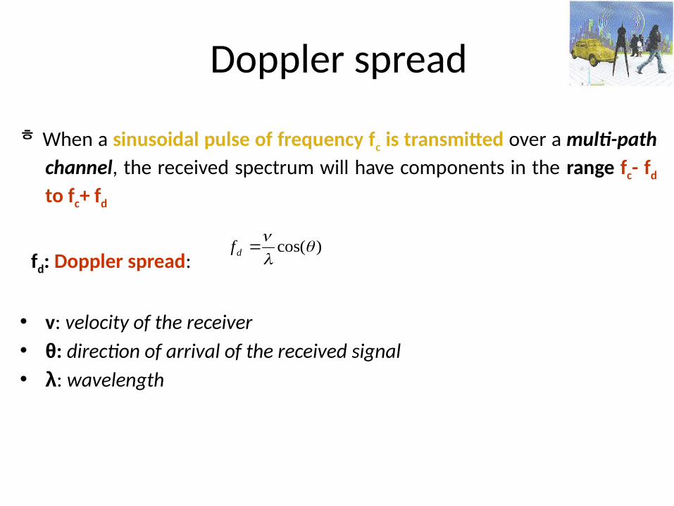
Doppler spread
When a sinusoidal pulse of frequency fc is transmitted over a multi-path channel, the received spectrum will have components in the range fc- fd to fc+ fd
fd: Doppler spread:
• v: velocity of the receiver• θ: direction of arrival of the received signal• λ: wavelength
)cos(
df
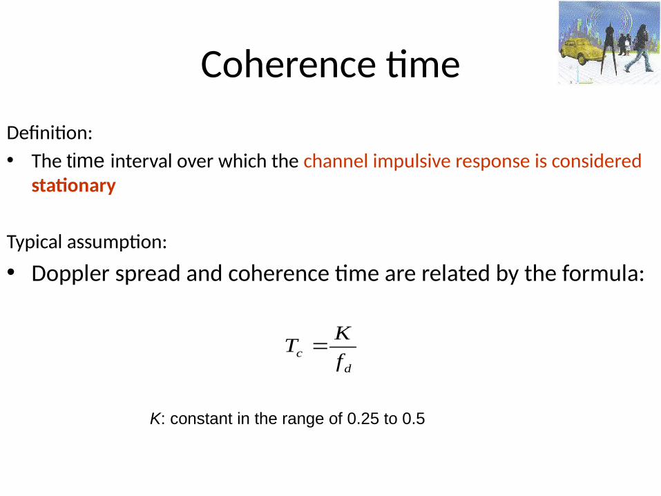
Coherence time
Definition:• The time interval over which the channel impulsive response is considered
stationary
Typical assumption:
• Doppler spread and coherence time are related by the formula:
K: constant in the range of 0.25 to 0.5
dc f
KT
Time Variance: Fast Fading
• The channel changes drastically many times while a symbol is propagating
Causing:• Severe distortion of baseband pulse leading to
detection problems• Loss in SNR• Synchronization problems
110
Time Variance: Slow Fading
• The channel does NOT change drastically during the symbol propagation
causing: Loss in SNR
111
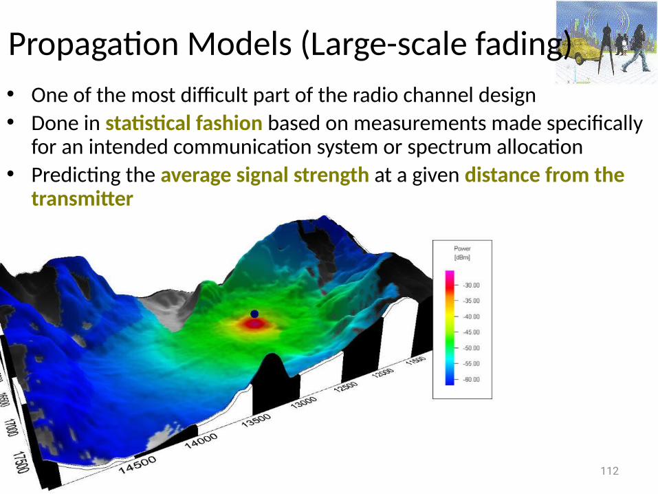
Propagation Models (Large-scale fading)• One of the most difficult part of the radio channel design• Done in statistical fashion based on measurements made specifically
for an intended communication system or spectrum allocation• Predicting the average signal strength at a given distance from the
transmitter
112
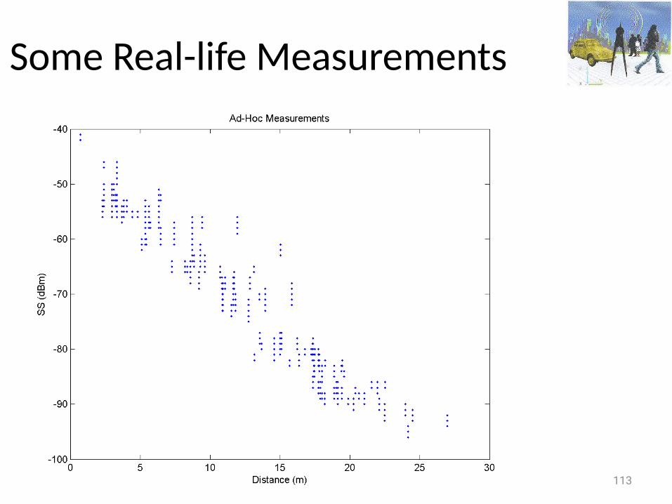
Some Real-life Measurements
113
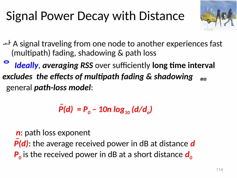
Signal Power Decay with Distance
A signal traveling from one node to another experiences fast (multipath) fading, shadowing & path loss Ideally, averaging RSS over sufficiently long time interval excludes the effects of multipath fading & shadowing general path-loss model:
P(d) = P0 – 10n log10 (d/do)
n: path loss exponent P(d): the average received power in dB at distance d P0 is the received power in dB at a short distance d0
114
_
_
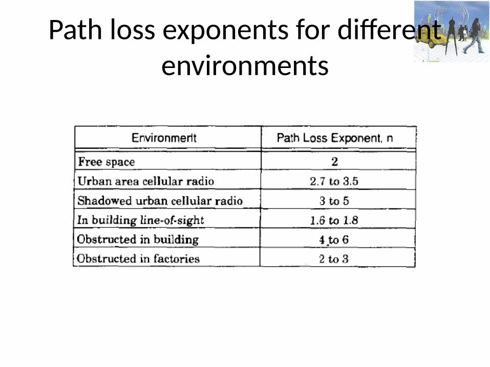
Path loss exponents for different environments
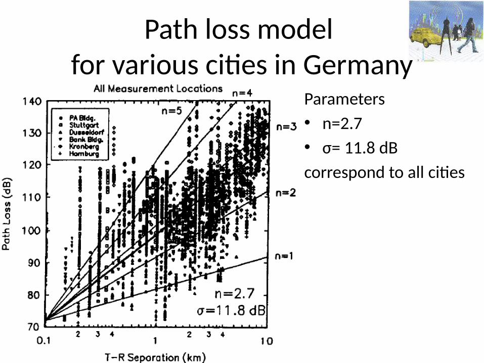
Path loss model for various cities in Germany
Parameters • n=2.7 • σ= 11.8 dBcorrespond to all cities
Free-space Propagation Model
• Assumes a single direct path between the base station and the mobile • Predicts received signal strength when the transmitter & receiver have a
clear, unobstructed line-of-sight path between them • Typically used in an open wide environment Examples: satellite, microwave line-of-sight radio links
118
Free-space Propagation Model
119
Derived from first principles: power flux density computation
• Any radiating structure produces electric & magnetic fields: its current flows through such antenna and launches electric and magnetic fields• The electrostatic and inductive fields decay much faster with distance than the radiation field
• At regions far way from the transmitter: the electrostatic & inductive fields become negligible and only the radiated field components need be considered
Free-space Propagation Model
120
Pr(d)=PtGtGr2/[(4)2d2L]
Pt,Pr: transmitter/receiver power Gt, Gr: transmitter/receiver antenna gain G = 4Ae/2
L: system loss factor (L=1 no loss) Ae: related to the physical size of the antenna: wavelength in meters, f carrier frequency, c :speed of light = c/f
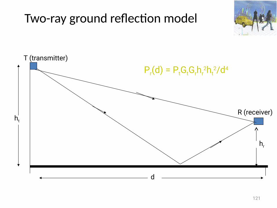
Two-ray ground reflection model
121
d
T (transmitter)
R (receiver)ht
hr
Pr(d) = PtGtGrhr2ht
2/d4
Two-ray Ground Reflection ModelConsiders both the direct path & a ground reflected propagation path
between transmitter and receiver• Reasonably accurate for predicting the large-scale signal strength 1. over distances of several km for mobile radio systems that use tall
tower (heights which exceed 40m) 2. for line-of-sight micro-cell channels in urban environment
122
Multiple Reflectors
• Use ray tracing• Modeling the received waveform as the sum of the responses from the
different paths rather than just two paths• Finding the magnitudes and phases of these responses is not a simple
task
123
Multi-path Delay Spread
• Difference in propagation time between the longest and shortest path, counting only the paths with significant energy
124
Modeling Electromagnetic Field
• In the cellular bands the wavelength is a fraction of meter• To calculate the electromagnetic field at the receiver, the locations of the
receiver and the obstructions would have to be known with sub-meter accuracies.
125
Free space Fixed transmit & Receive Antennas
In the far field, the electric field and magnetic field at any given location are• perpendicular both to each other & to the direction of propagation from
the antenna• proportional to each other
126
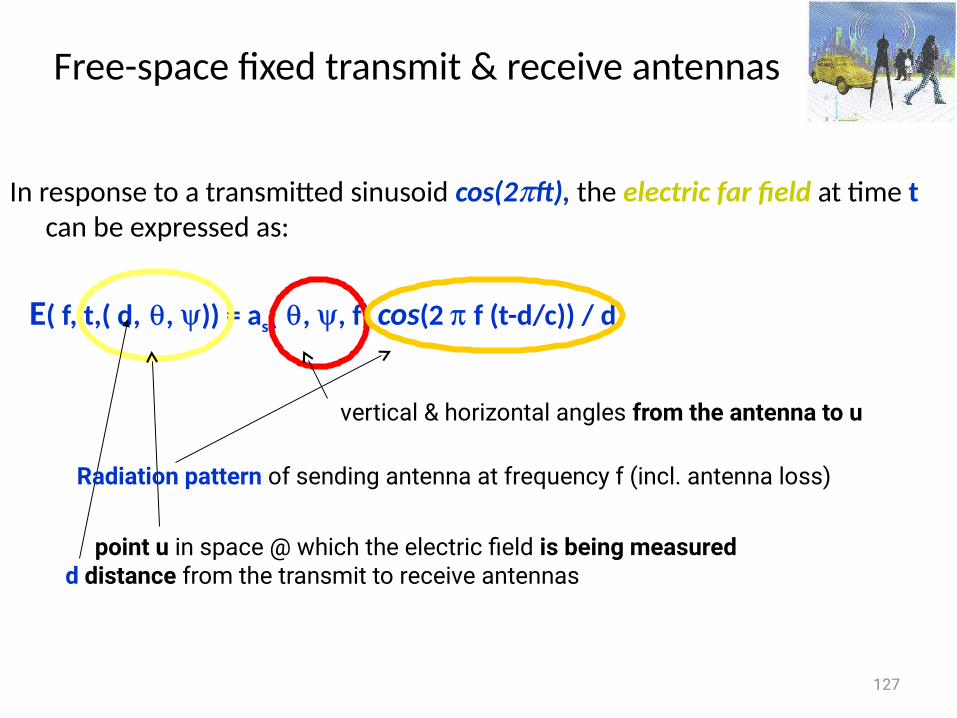
Free-space fixed transmit & receive antennas
In response to a transmitted sinusoid cos(2ft), the electric far field at time t can be expressed as:
E( f, t,( d,, )) = as(, , f) cos(2 f (t-d/c)) / d
127
point u in space @ which the electric field is being measuredd distance from the transmit to receive antennas
vertical & horizontal angles from the antenna to u
Radiation pattern of sending antenna at frequency f (incl. antenna loss)
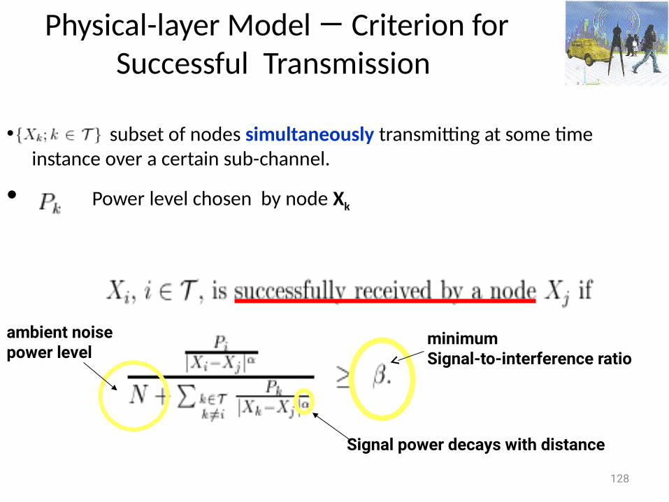
Physical-layer Model — Criterion for Successful Transmission
• subset of nodes simultaneously transmitting at some time instance over a certain sub-channel.
• Power level chosen by node Xk
128
minimumSignal-to-interference ratio
Signal power decays with distance
ambient noise power level
Signal-to-noise ratio (SNR)
• The ratio between the magnitude of background noise and the magnitude of un-distorted signal (meaningful information) on a channel
• Higher SNR is better (i.e., cleaner)• It determines how much information each symbol can represent
129
Capacity of a channel
How many bits of information can be transmitted without error per sec over a channel with
• bandwidth B • average signal power P • the signal is exposed to an additive, white (uncorrelated) noise
of power N with Gaussian probability distribution
130
provides the fundamental limit of communication achievable by any scheme
Limits of wireless channel
• Shannon [1948] defined the capacity limit for communication channels
131
Shannon (1916-2001) Norbert Wiener (1894-1964)
Shannon’s limit
• For a channel without shadowing, fading, or ISI, the maximum possible data rate on a given channel of bandwidth B is
R=Blog2(1+SNR) bps,
where SNR is the received signal to noise ratio
Shannon’s is a theoretical limit that cannot be achieved in practice but design techniques improve data rates to approach this bound
132
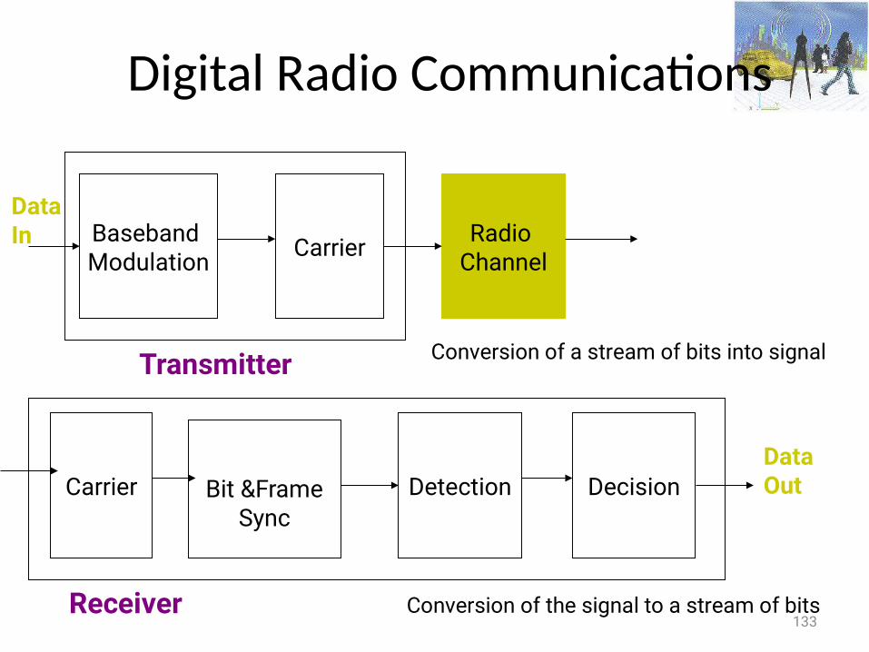
Digital Radio Communications
133
Baseband Modulation Carrier Radio
Channel
Transmitter
DataIn
Carrier Bit &FrameSync
Detection
Receiver
DecisionDataOut
Conversion of a stream of bits into signal
Conversion of the signal to a stream of bits

Conversion of a stream of bits into signal
134
Adds redundancyBits mapped to signal (analog signal waveform)
noiseInterferenceFading
protects from interference
Conversion of a stream of bits into signal
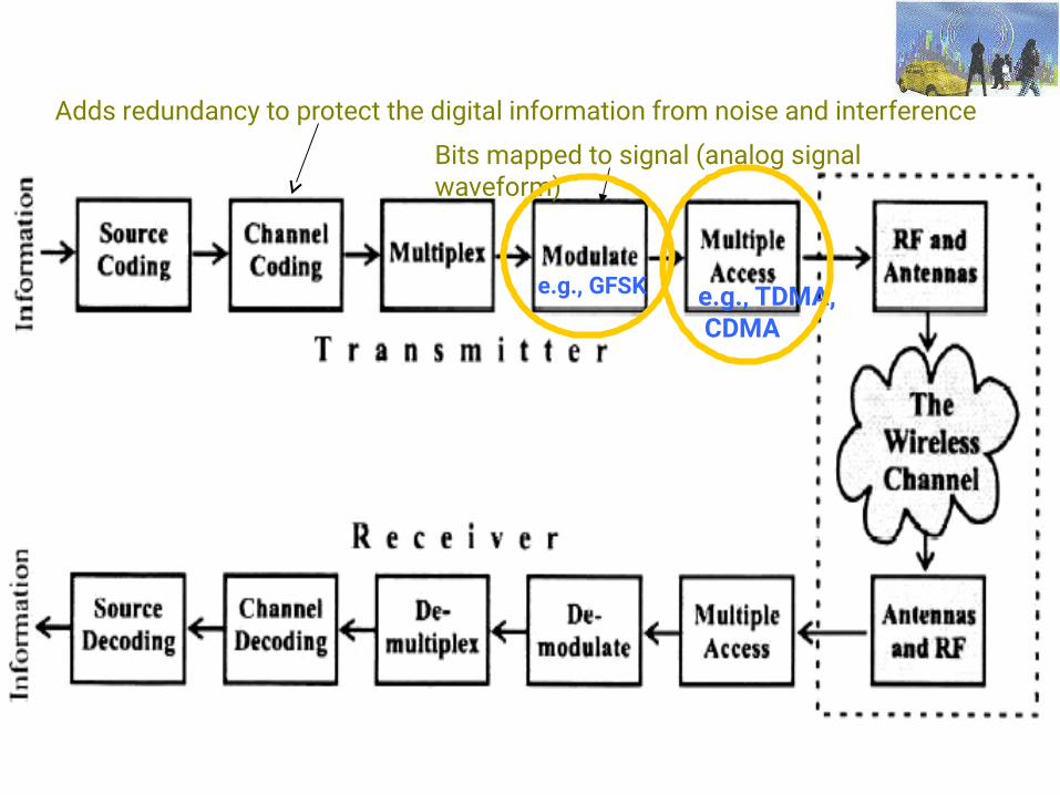
135
Adds redundancy to protect the digital information from noise and interference
Bits mapped to signal (analog signal waveform)
e.g., GFSK e.g., TDMA, CDMA
Channel Coding
• Protects the digital information from noise & interference & reduces the number of bit errors
• Accomplished by selectively introducing redundant bits into the transmitted information stream
• These additional bits allow detection & correction of bit errors in the received data stream
136
137
Encoding
• Use two discrete signals, high and low, to encode 0 and 1• Transmission is synchronous, i.e., a clock is used to sample the signal
– In general, the duration of one bit is equal to one or two clock ticks– Receiver’s clock must be synchronized with the sender’s clock
• Encoding can be done one bit at a time or in blocks of, e.g., 4 or 8 bits
138
Why Do We Need Encoding?
• Meet certain electrical constraints– Receiver needs enough “transitions” to keep track of the transmit clock– Avoid receiver saturation
• Create control symbols, besides regular data symbol e.g. start or end of frame
• Error detection or error corrections– Some codes are illegal so receiver can detect certain classes of errors– Minor errors can be corrected by having multiple adjacent signals mapped to
the same data symbol
• Encoding can be very complex, e.g. wireless
Digital Modulation
The process of • taking information from a message source (baseband) in a suitable
manner for transmission &• translating the baseband signal onto a radio carrier at frequencies
that are very high compared to the baseband frequency
139
140
Why not modulate the baseband
For effective signal radiation the length of the antenna must be proportional to the transmitted wave length– For example, voice range 300-3300Hz At 3kHz at 3kbps would imply an antenna of 100Km! By modulating the baseband on a 3GHz carrier the antenna would be
10cm
• To ensure the orderly coexistence of multiple signals in a given spectral band• To help reduce interference among users• For regulatory reasons
Demodulation
The process of extracting the baseband from the carrier so that it may be processed and interpreted by the receiver (e.g., symbols detected and extracted)
141
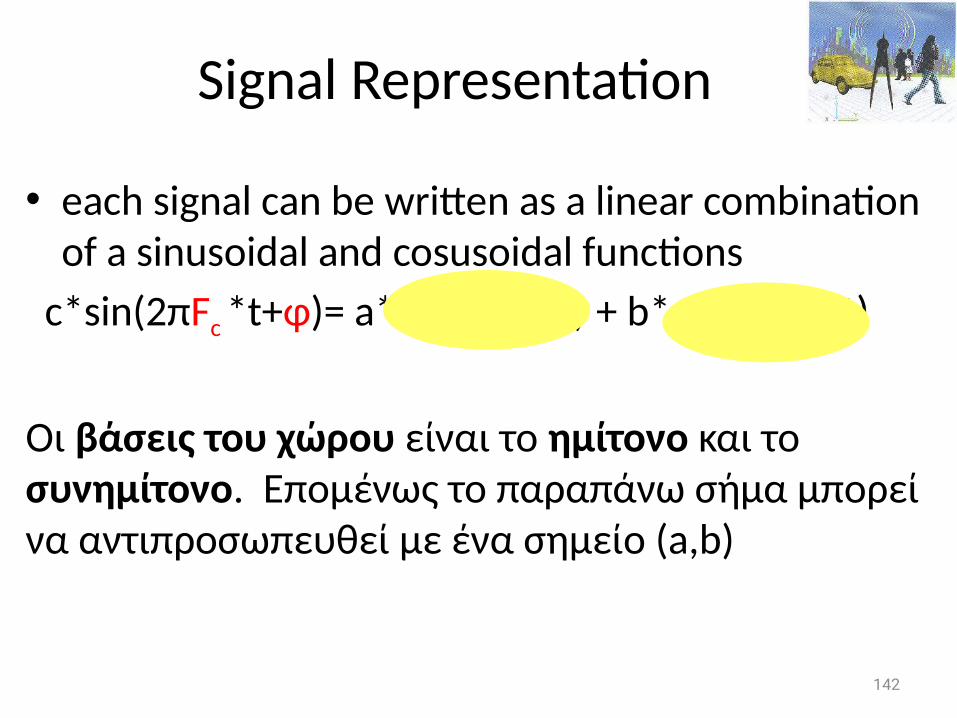
Signal Representation
• each signal can be written as a linear combination of a sinusoidal and cosusoidal functions
c*sin(2πFc *t+φ)= a*sin(2πFc *t) + b*cos(2πFc *t)
Οι βάσεις του χώρου είναι το ημίτονο και το συνημίτονο. Επομένως το παραπάνω σήμα μπορεί να αντιπροσωπευθεί με ένα σημείο (a,b)
142

Signal Representation
• each signal can be written as a linear combination of a sinusoidal and cosusoidal functions
c*sin(2πFc *t+φ)= a*sin(2πFc *t) + b*cos(2πFc *t)
Οι βάσεις του χώρου είναι το ημίτονο και το συνημίτονο. Επομένως το παραπάνω σήμα μπορεί να αντιπροσωπευθεί με ένα σημείο (a,b)
143
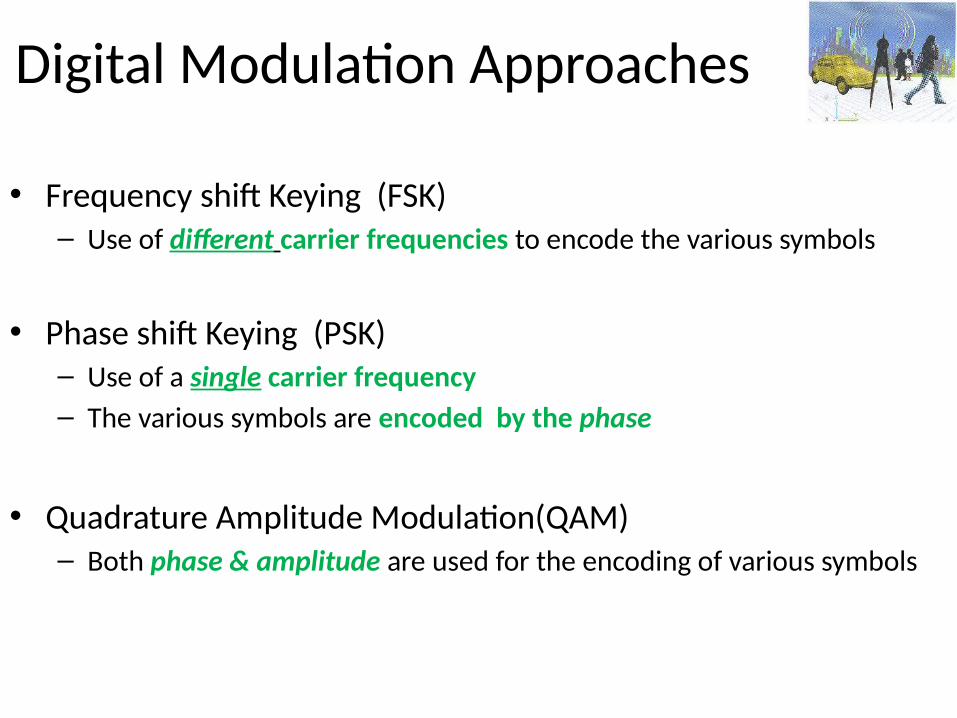
Digital Modulation Approaches
• Frequency shift Keying (FSK)– Use of different carrier frequencies to encode the various symbols
• Phase shift Keying (PSK)– Use of a single carrier frequency– The various symbols are encoded by the phase
• Quadrature Amplitude Modulation(QAM)– Both phase & amplitude are used for the encoding of various symbols
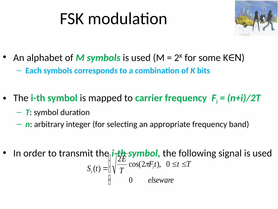
FSK modulation
• An alphabet of M symbols is used (M = 2K for some K N∈ )– Each symbols corresponds to a combination of K bits
• The i-th symbol is mapped to carrier frequency Fi = (n+i)/2T– T: symbol duration – n: arbitrary integer (for selecting an appropriate frequency band)
• In order to transmit the i-th symbol, the following signal is used
elseware
TttFT
EtS i
i
0
0),2cos(2
)(
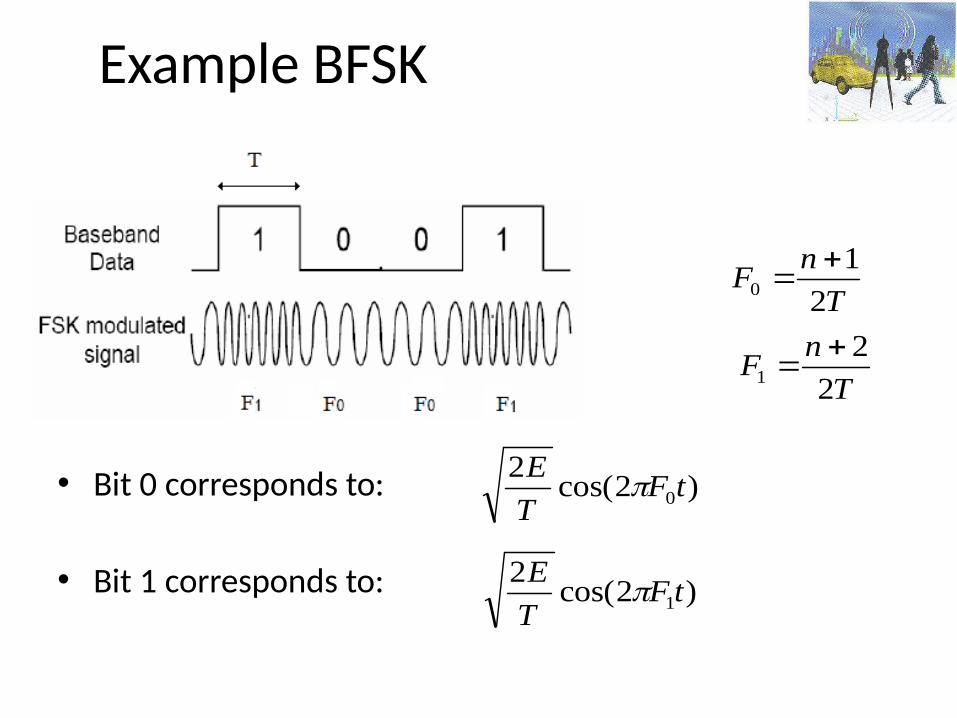
Example BFSK
• Bit 0 corresponds to:
• Bit 1 corresponds to:
)2cos(2
0tFT
E
)2cos(2
1tFT
E
T
nF
2
10
T
nF
2
21
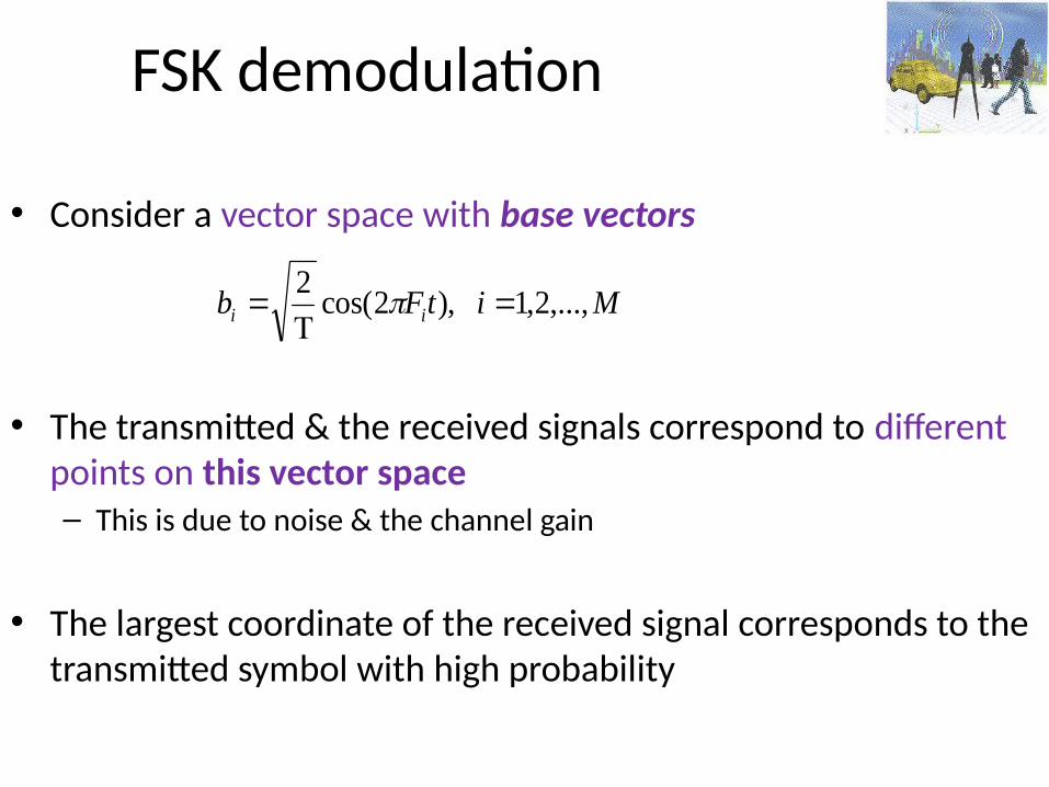
FSK demodulation
• Consider a vector space with base vectors
• The transmitted & the received signals correspond to different points on this vector space– This is due to noise & the channel gain
• The largest coordinate of the received signal corresponds to the transmitted symbol with high probability
MitFb ii ,...,2,1),2cos(2
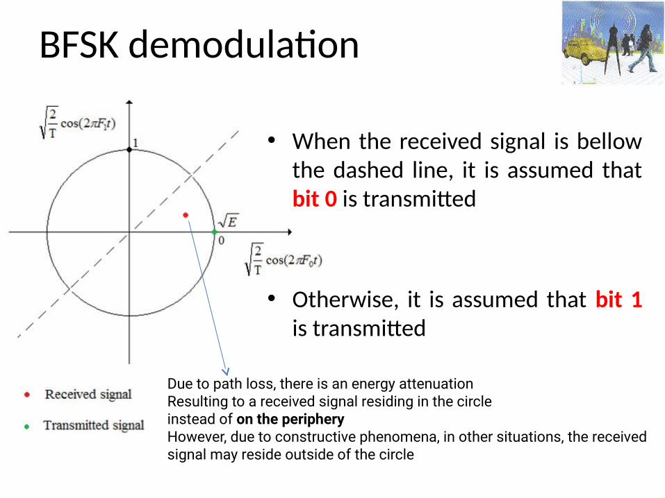
BFSK demodulation
• When the received signal is bellow the dashed line, it is assumed that bit 0 is transmitted
• Otherwise, it is assumed that bit 1 is transmitted
Due to path loss, there is an energy attenuationResulting to a received signal residing in the circleinstead of on the peripheryHowever, due to constructive phenomena, in other situations, the received signal may reside outside of the circle
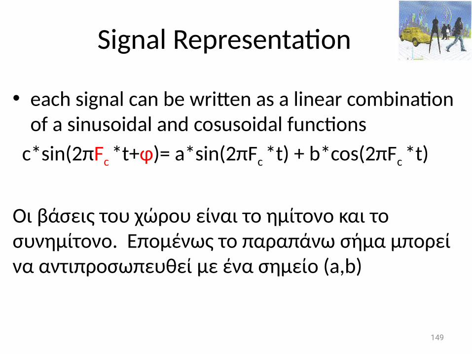
Signal Representation
• each signal can be written as a linear combination of a sinusoidal and cosusoidal functions
c*sin(2πFc *t+φ)= a*sin(2πFc *t) + b*cos(2πFc *t)
Οι βάσεις του χώρου είναι το ημίτονο και το συνημίτονο. Επομένως το παραπάνω σήμα μπορεί να αντιπροσωπευθεί με ένα σημείο (a,b)
149
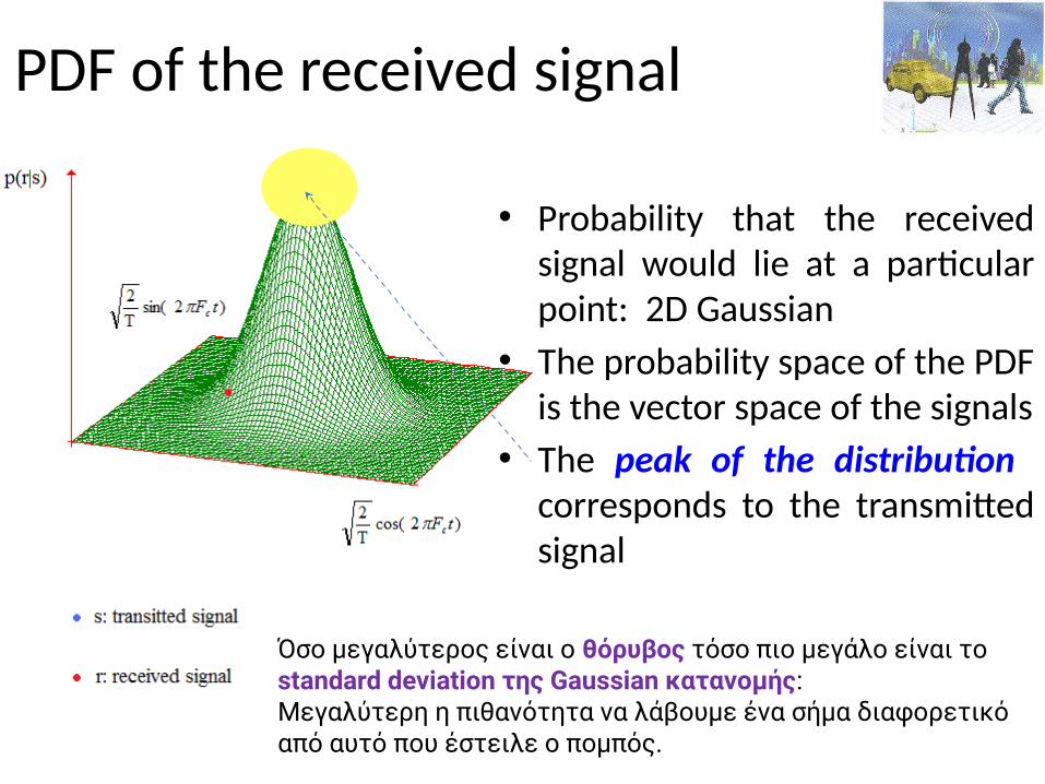
PDF of the received signal
• Probability that the received signal would lie at a particular point: 2D Gaussian
• The probability space of the PDF is the vector space of the signals
• The peak of the distribution corresponds to the transmitted signal
Όσο μεγαλύτερος είναι ο θόρυβος τόσο πιο μεγάλο είναι το standard deviation της Gaussian κατανομής:Μεγαλύτερη η πιθανότητα να λάβουμε ένα σήμα διαφορετικό από αυτό που έστειλε ο πομπός.
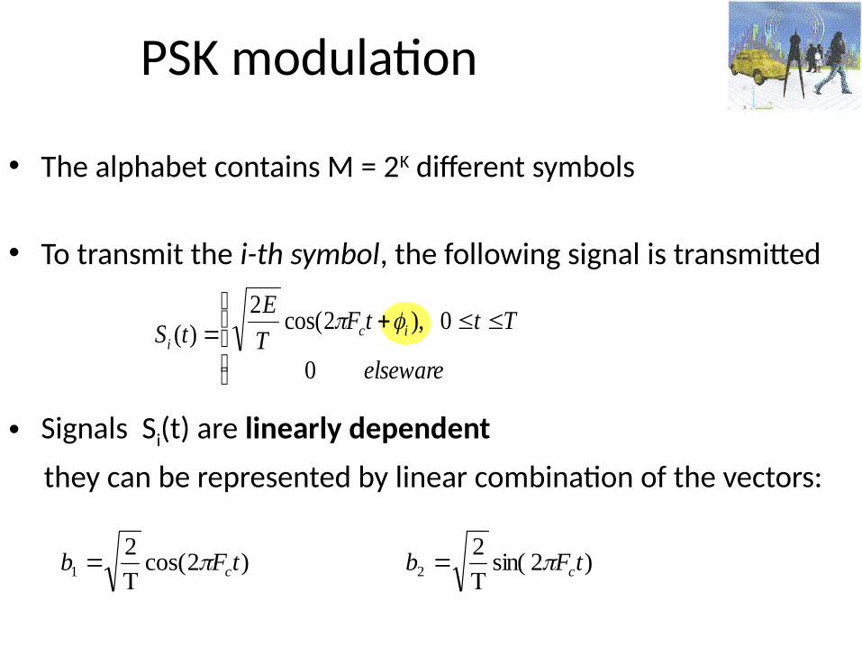
PSK modulation
• The alphabet contains M = 2K different symbols
• To transmit the i-th symbol, the following signal is transmitted
• Signals Si(t) are linearly dependent
they can be represented by linear combination of the vectors:
elseware
TttFT
EtS ic
i
0
0),2cos(2
)(
)2cos(2
1 tFb c
)2sin(2
2 tFb c
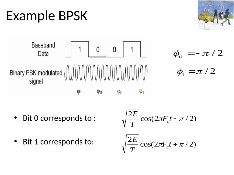
Example BPSK
• Bit 0 corresponds to :
• Bit 1 corresponds to:
2/
2/1
)2/2cos(2
tFT
Ec
)2/2cos(2
tFT
Ec
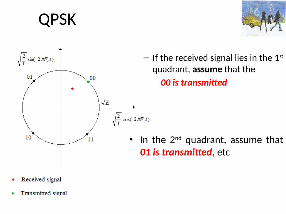
QPSK
– If the received signal lies in the 1st quadrant, assume that the
00 is transmitted
• In the 2nd quadrant, assume that 01 is transmitted, etc
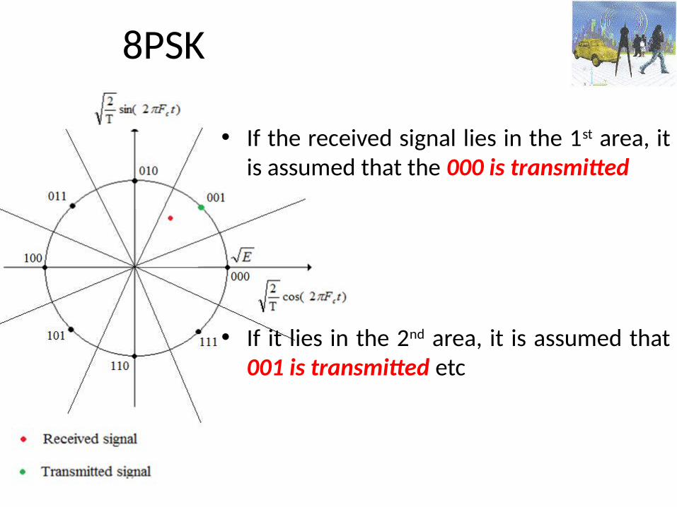
8PSK
• If the received signal lies in the 1st area, it is assumed that the 000 is transmitted
• If it lies in the 2nd area, it is assumed that 001 is transmitted etc
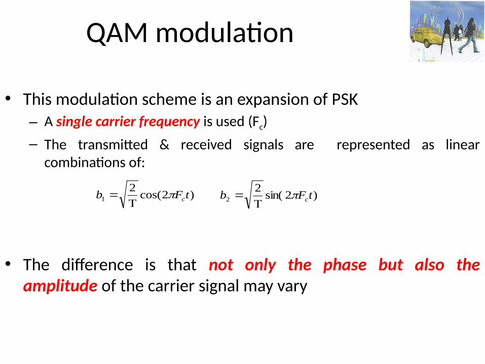
QAM modulation
• This modulation scheme is an expansion of PSK– A single carrier frequency is used (Fc)– The transmitted & received signals are represented as linear
combinations of:
• The difference is that not only the phase but also the amplitude of the carrier signal may vary
)2cos(2
1 tFb c
)2sin(2
2 tFb c
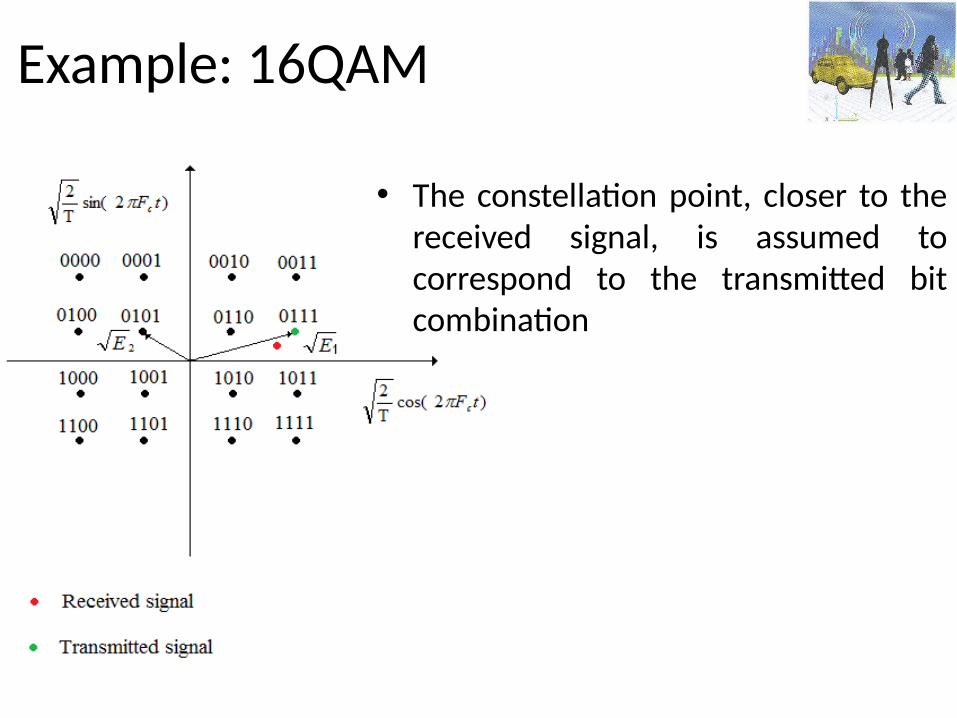
Example: 16QAM
• The constellation point, closer to the received signal, is assumed to correspond to the transmitted bit combination

PDF of the received signal
• Probability that the received signal would lie at a particular point: 2D Gaussian
• The probability space of the PDF is the vector space of the signals
• The peak of the distribution corresponds to the transmitted signal
Όσο μεγαλύτερος είναι ο θόρυβος τόσο πιο μεγάλο είναι το standard deviation της Gaussian κατανομής:Μεγαλύτερη η πιθανότητα να λάβουμε ένα σήμα διαφορετικό από αυτό που έστειλε ο πομπός.
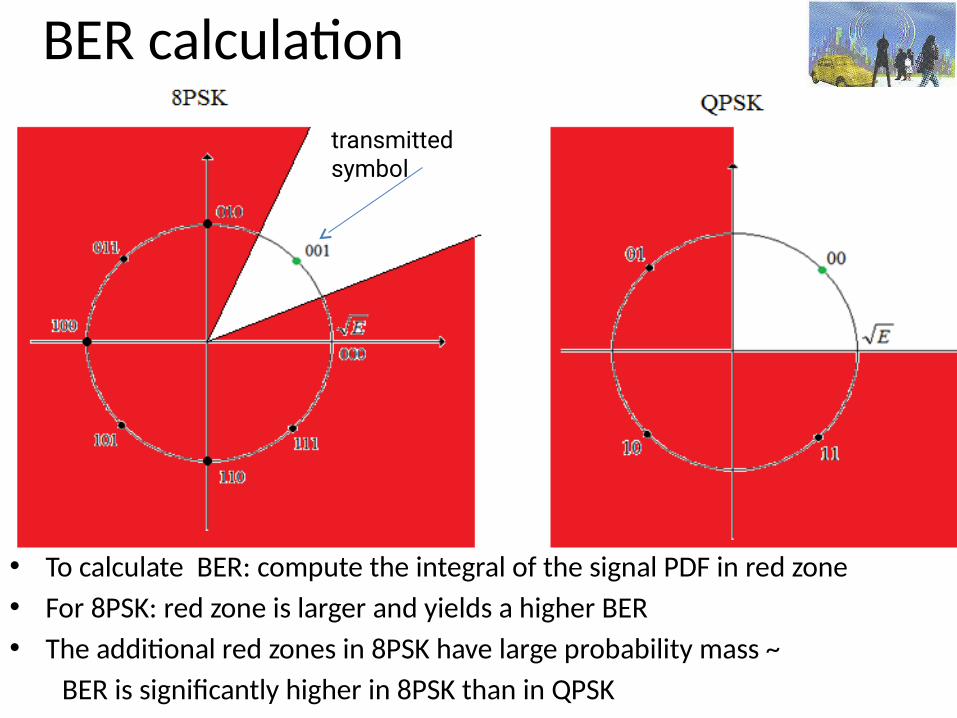
BER calculation
• To calculate BER: compute the integral of the signal PDF in red zone• For 8PSK: red zone is larger and yields a higher BER• The additional red zones in 8PSK have large probability mass ~ BER is significantly higher in 8PSK than in QPSK
transmitted symbol
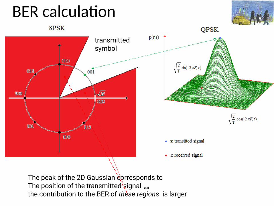
BER calculationtransmitted symbol
The peak of the 2D Gaussian corresponds toThe position of the transmitted signal the contribution to the BER of these regions is larger
160
Gaussian frequency shift keying (GFSK)
• Encodes data as a series of frequency changes in a carrier• Noise usually changes the amplitude of a signal
• Modulation that ignores amplitude (e.g., broadcast FM) Relatively immune to noise
• Gaussian refers to the shape of radio pulses
161
2GFSK
Two different frequencies
• To transmit 1– The carrier frequency is increased by a certain deviation
• To transmit 0– The carrier frequency is decreased by the same deviation
162
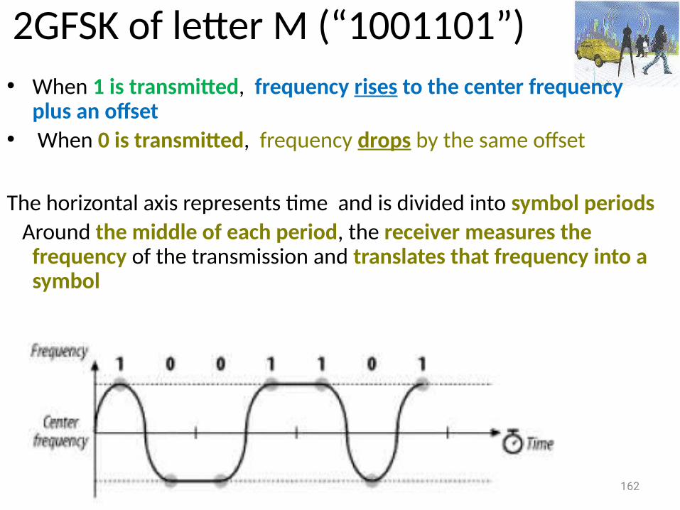
2GFSK of letter M (“1001101”)• When 1 is transmitted, frequency rises to the center frequency
plus an offset• When 0 is transmitted, frequency drops by the same offset
The horizontal axis represents time and is divided into symbol periods Around the middle of each period, the receiver measures the
frequency of the transmission and translates that frequency into a symbol
163
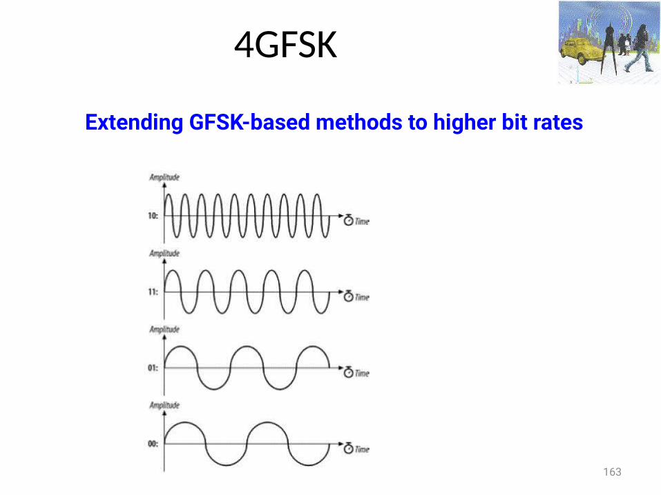
4GFSK
Extending GFSK-based methods to higher bit rates
164
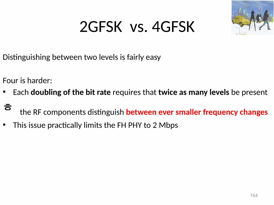
2GFSK vs. 4GFSK
Distinguishing between two levels is fairly easy
Four is harder:• Each doubling of the bit rate requires that twice as many levels be present
the RF components distinguish between ever smaller frequency changes • This issue practically limits the FH PHY to 2 Mbps
165
Differential Phase Shift Keying (DPSK)
• Basis of 802.11 DSSS• Absolute phase of waveform is not relevant • Only changes in the phase encode data• Two carrier waves
– Shifted by a half cycle relative to each other– Reference wave: encodes 0– Half-cycle (180o) shifted wave: encodes 1
166
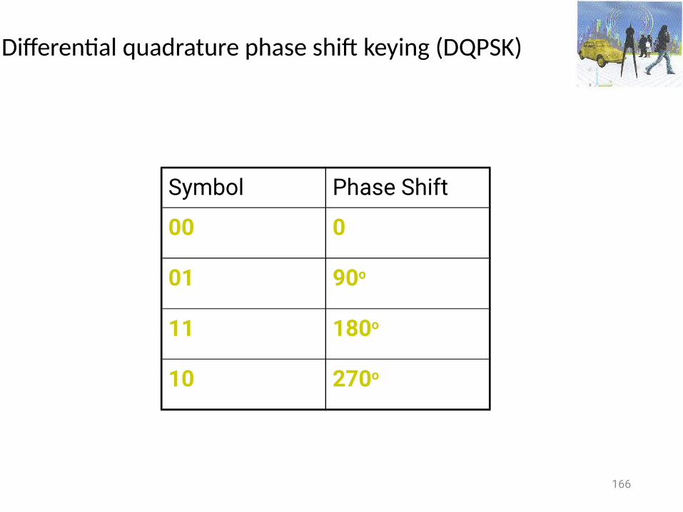
Differential quadrature phase shift keying (DQPSK)
Symbol Phase Shift
00 0
01 90o
11 180o
10 270o
167
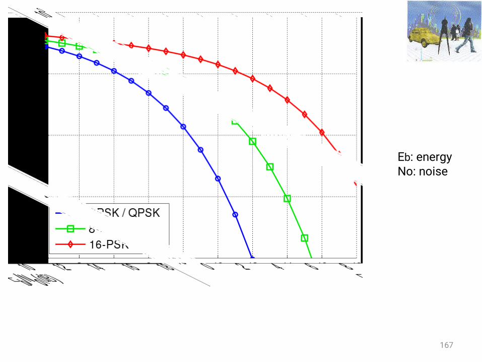
Eb: energyNo: noise
168
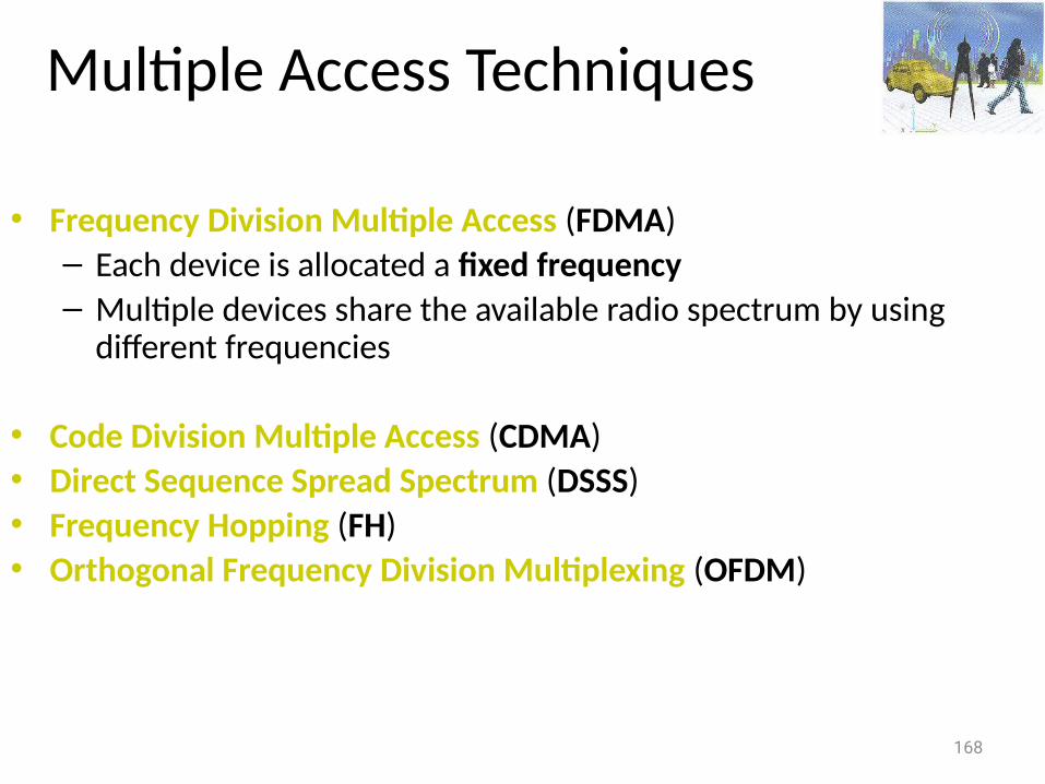
Multiple Access Techniques
• Frequency Division Multiple Access (FDMA)– Each device is allocated a fixed frequency– Multiple devices share the available radio spectrum by using
different frequencies
• Code Division Multiple Access (CDMA) • Direct Sequence Spread Spectrum (DSSS) • Frequency Hopping (FH)• Orthogonal Frequency Division Multiplexing (OFDM)
169
Spread spectrum
• Traditional radio communications focus on cramming as much signal as possible into as narrow a band as possible
• Spread spectrum use mathematical functions to diffuse signal power over large range of frequencies
• Spreading the transmission over wide band makes transmission look like noise to a traditional narrowband receiver
170
Spread Spectrum Technology
• Spread radio signal over a wide frequency range several magnitudes higher than minimum requirement
• Use of noise-like carrier waves and bandwidths much wider than that required for simple point-to-point communication at the same data rate
• Electromagnetic energy generated in a particular bandwidth is deliberately spread in the frequency domain, resulting in a signal with a wider bandwidth
• Used for a variety of reasons– establishment of secure communications– increasing resistance to natural interference and jamming– prevent detection
• Two main techniques: – Direct sequence (DS) – Frequency hopping (FH)
171
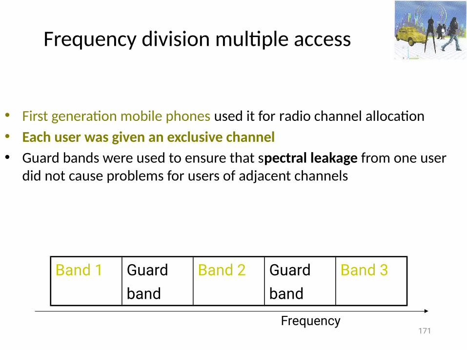
Frequency division multiple access
• First generation mobile phones used it for radio channel allocation• Each user was given an exclusive channel• Guard bands were used to ensure that spectral leakage from one user
did not cause problems for users of adjacent channels
Band 1 Guardband
Band 2 Guardband
Band 3
Frequency
172
Problems with FDMA ?
• Wasting transmission capacity with unused guard bands …
173
Code division multiple access (CDMA)
• CDMA assigns a different code to each node• Codes orthogonal to each other (i.e inner-product = 0)• Each node uses its unique code to encode the data bits it sends• Nodes can transmit simultaneously• Multiple nodes per channel• Their respective receivers
– Correctly receive a sender’s encoded data bits • Assuming the receiver knows the sender’s code in spite of
interfering transmissions by other nodes
174
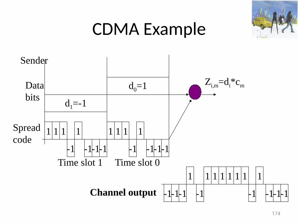
CDMA Example
d1=-1
d0=1
Sender
Databits
1 1 1
-1
111
-1-1-1
1
-1
1
-1-1-1
Zi,m=di*cm
Time slot 1 Time slot 0
-1-1
1
-1
111
-1-1-1-1
1
-1
111
Channel output
Spreadcode
175
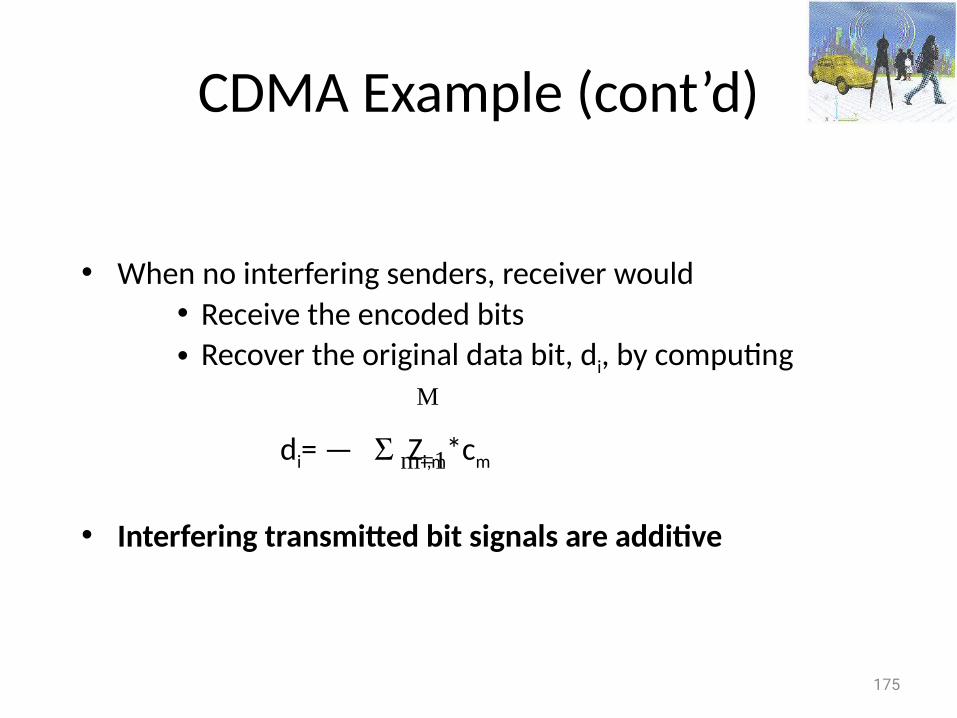
CDMA Example (cont’d)
• When no interfering senders, receiver would • Receive the encoded bits • Recover the original data bit, di, by computing
di= — Zi,m*cm
• Interfering transmitted bit signals are additive
m=1
M
176
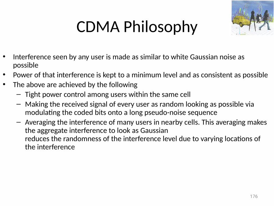
CDMA Philosophy
• Interference seen by any user is made as similar to white Gaussian noise as possible
• Power of that interference is kept to a minimum level and as consistent as possible• The above are achieved by the following
– Tight power control among users within the same cell– Making the received signal of every user as random looking as possible via
modulating the coded bits onto a long pseudo-noise sequence– Averaging the interference of many users in nearby cells. This averaging makes
the aggregate interference to look as Gaussianreduces the randomness of the interference level due to varying locations of the interference
177
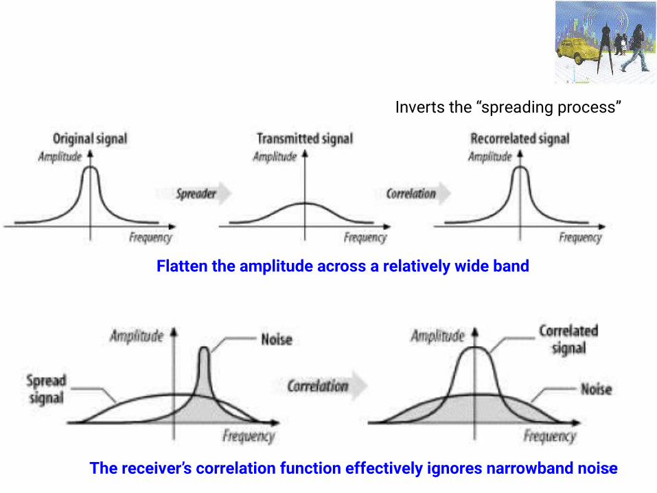
Flatten the amplitude across a relatively wide band
Inverts the “spreading process”
The receiver’s correlation function effectively ignores narrowband noise
178
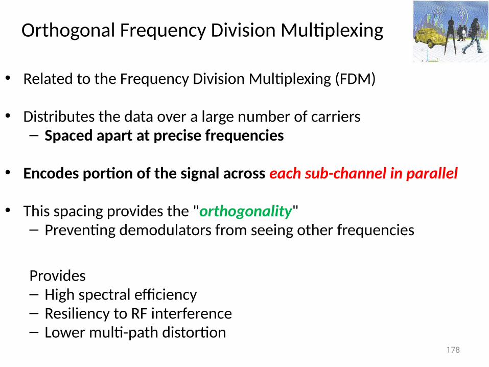
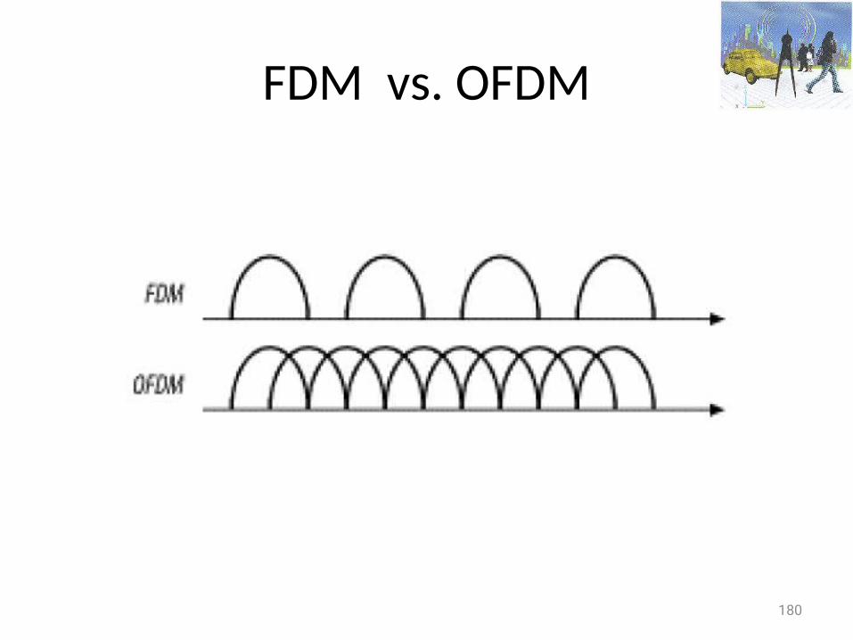
Orthogonal Frequency Division Multiplexing
• Related to the Frequency Division Multiplexing (FDM)
• Distributes the data over a large number of carriers – Spaced apart at precise frequencies
• Encodes portion of the signal across each sub-channel in parallel
• This spacing provides the "orthogonality" – Preventing demodulators from seeing other frequencies
Provides– High spectral efficiency– Resiliency to RF interference– Lower multi-path distortion
179
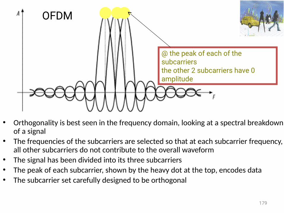
OFDM
• Orthogonality is best seen in the frequency domain, looking at a spectral breakdown of a signal
• The frequencies of the subcarriers are selected so that at each subcarrier frequency, all other subcarriers do not contribute to the overall waveform
• The signal has been divided into its three subcarriers• The peak of each subcarrier, shown by the heavy dot at the top, encodes data• The subcarrier set carefully designed to be orthogonal
@ the peak of each of the subcarriersthe other 2 subcarriers have 0 amplitude
OFDM
180
FDM vs. OFDM
181
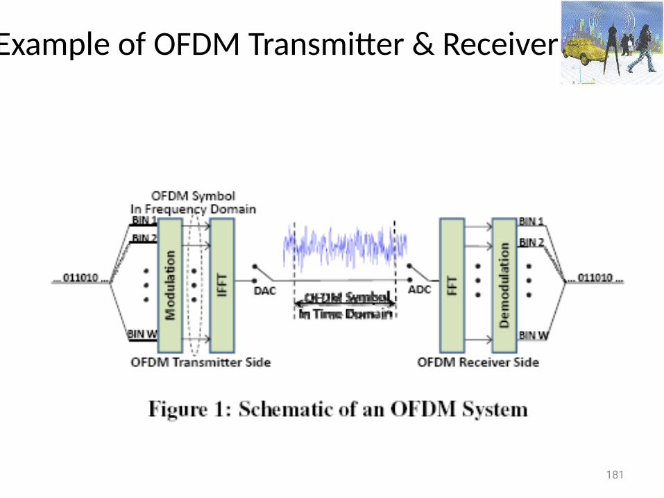
Example of OFDM Transmitter & Receiver
182
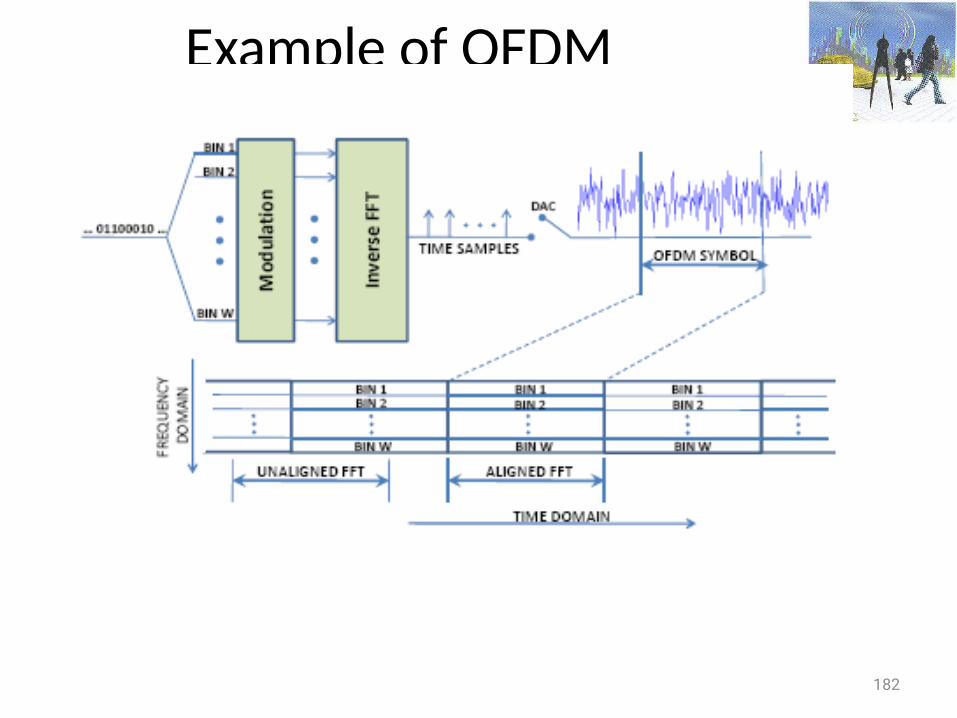
Example of OFDM
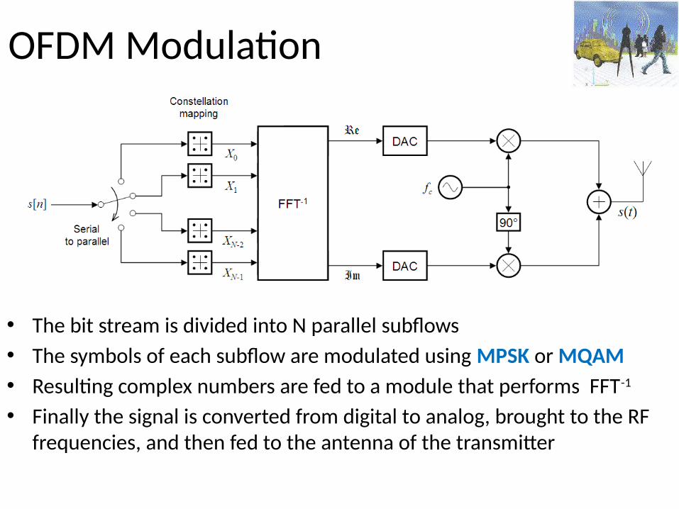
OFDM Modulation
• The bit stream is divided into N parallel subflows• The symbols of each subflow are modulated using MPSK or MQAM • Resulting complex numbers are fed to a module that performs FFT-1 • Finally the signal is converted from digital to analog, brought to the RF
frequencies, and then fed to the antenna of the transmitter
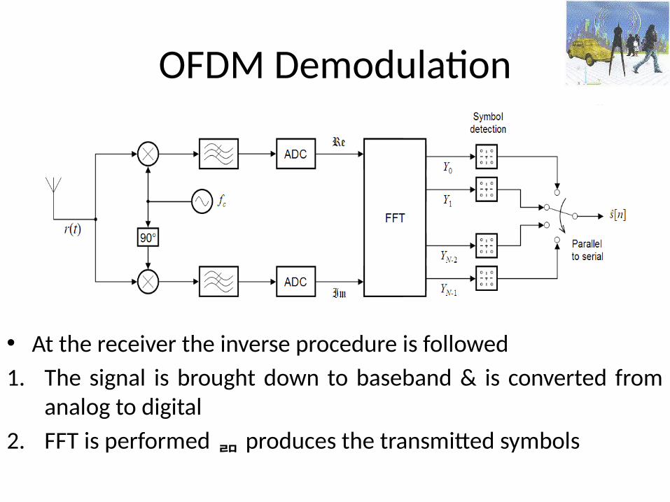
OFDM Demodulation
• At the receiver the inverse procedure is followed1. The signal is brought down to baseband & is converted from
analog to digital2. FFT is performed produces the transmitted symbols
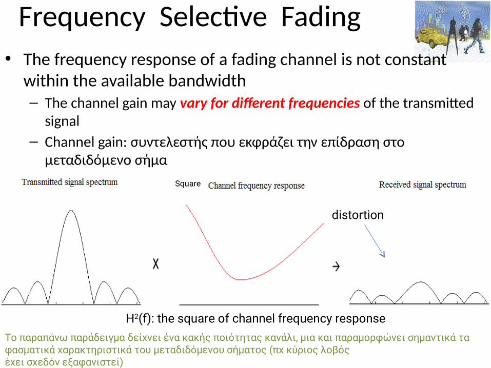
Frequency Selective Fading• The frequency response of a fading channel is not constant
within the available bandwidth– The channel gain may vary for different frequencies of the transmitted
signal– Channel gain: συντελεστής που εκφράζει την επίδραση στο
μεταδιδόμενο σήμα
H2(f): the square of channel frequency response
Square
distortion
Το παραπάνω παράδειγμα δείχνει ένα κακής ποιότητας κανάλι, μια και παραμορφώνει σημαντικά τα φασματικά χαρακτηριστικά του μεταδιδόμενου σήματος (πχ κύριος λοβόςέχει σχεδόν εξαφανιστεί)
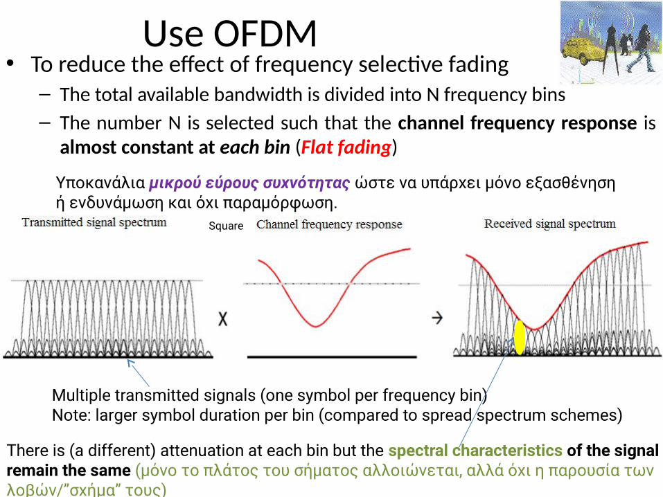
Use OFDM • To reduce the effect of frequency selective fading
– The total available bandwidth is divided into N frequency bins– The number N is selected such that the channel frequency response is
almost constant at each bin (Flat fading)
Square
There is (a different) attenuation at each bin but the spectral characteristics of the signal remain the same (μόνο το πλάτος του σήματος αλλοιώνεται, αλλά όχι η παρουσία των λοβών/”σχήμα” τους)
Multiple transmitted signals (one symbol per frequency bin)Note: larger symbol duration per bin (compared to spread spectrum schemes)
Υποκανάλια μικρού εύρους συχνότητας ώστε να υπάρχει μόνο εξασθένηση ή ενδυνάμωση και όχι παραμόρφωση.
187
CDMA vs. OFDM
• OFDM encodes single transmission into multiple subcarriers
• CDMA puts multiple transmissions into single carrier
188
Frequency Hopping
• Timing the hops accurately is the key• Transmitter and receiver in synch• Each frequency is used for small amount of time (dwell time)• Orthogonal hoping sequences• Beacons include timestamp and hop pattern number• Divides the ISM band into a series of 1-MHz channels• No sophisticated signal processing required
– To extract bit stream from the radio signal
189
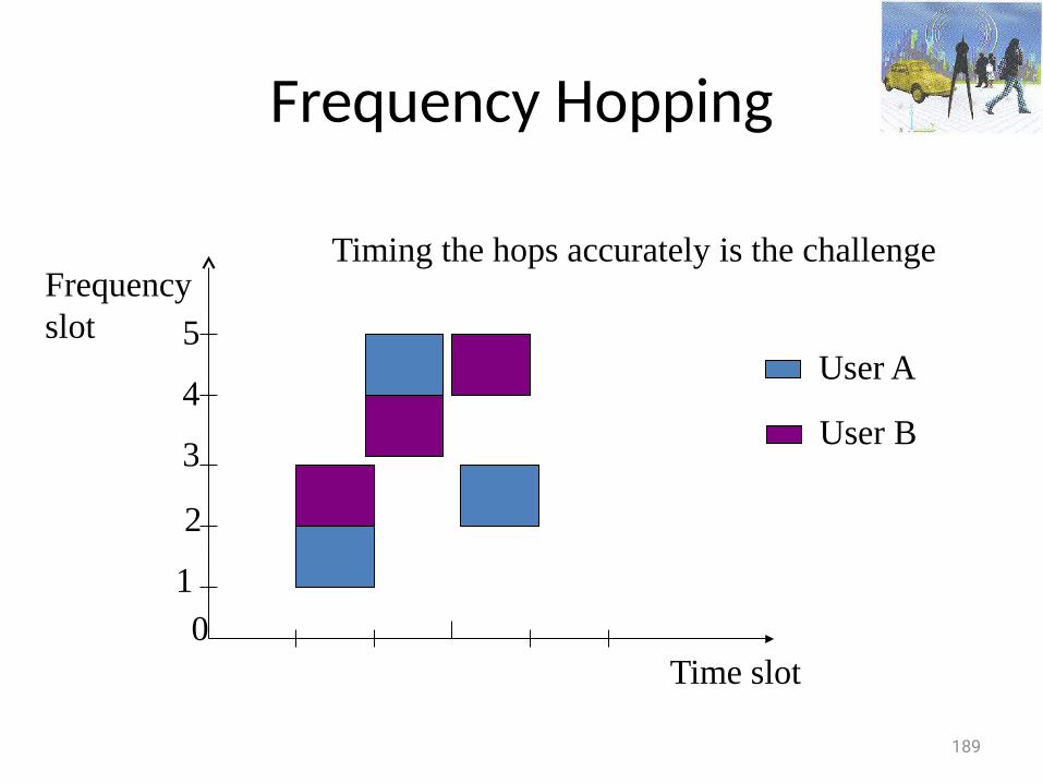
Frequency Hopping
Time slot
Frequencyslot
Timing the hops accurately is the challenge
01
2
3
4
5User A
User B
190
Wireless network interfaces
• Measure the energy level in a band• Energy detection is cheap, fast, & requires no knowledge of the characteristics of the
signal• However, choosing energy thresholds is not robust across a wide range of SNRs• Though more sophisticated mechanisms, such as matched filter detection, are more
accurate– they require knowledge of the transmitted signal (e.g., modulation, packet format, pilots,
bandwidth), and thus work only for known technologies
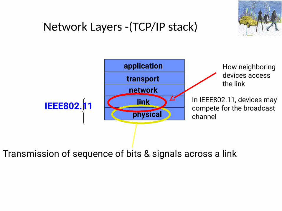
Network Layers -(TCP/IP stack)
physical
application
transportnetwork
link
Transmission of sequence of bits & signals across a link
How neighboringdevices accessthe link
In IEEE802.11, devices may compete for the broadcast channel
IEEE802.11
IEEE 802.11 Family
• 802.11b: Direct Sequence Spread Spectrum (DSSS) or Frequency Hopping (FH),
operates at 2.4GHz, 11Mbps bitrate
• 802.11a: between 5GHz and 6GHz uses orthogonal frequency-division multiplexing, up to 54Mbps bitrate
• 802.11g: operates at 2.4GHz up to 54Mbps bitrate• All have the same architecture & use the same MAC protocol
Coverage of a Cell• The largest distance between the base-station & a mobile at which
communication can reliably take place• Cell coverage is constrained by the fast decay of power with distance• To alleviate the inter-cell interference, neighboring cells use different parts of the
frequency spectrum• The rapid signal attenuation with distance is also helpful; it reduces the
interference between adjacent cells
Spatial reuse
193
Frequency is reused at cells that are far enough
194
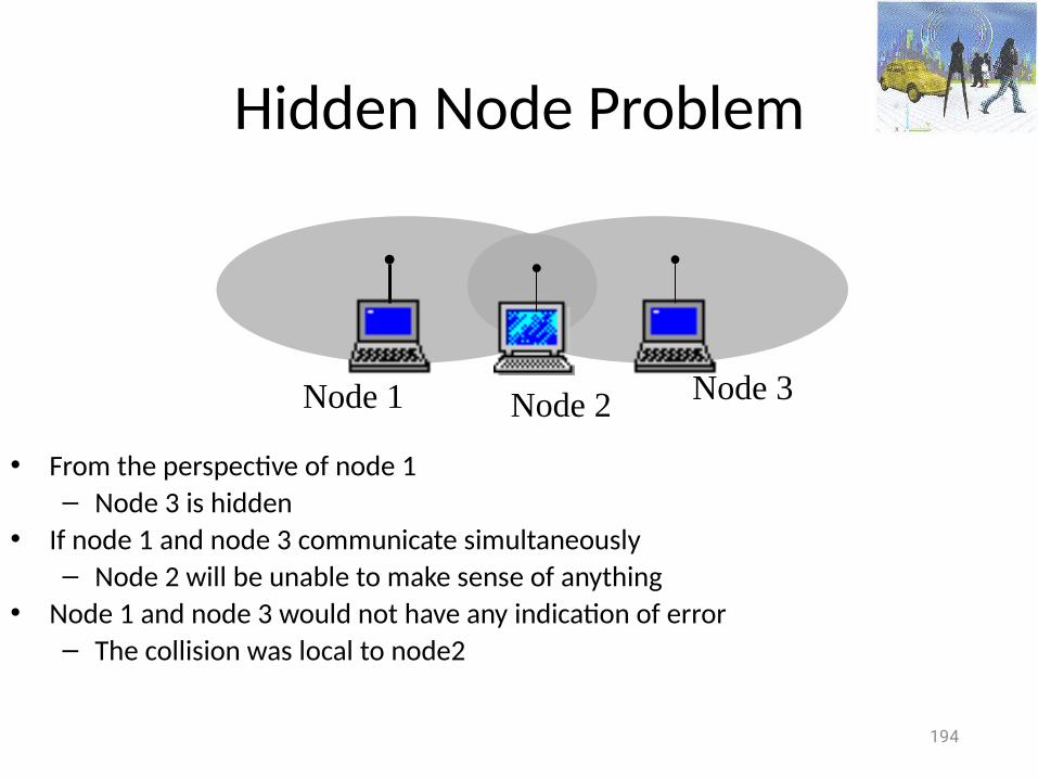
Hidden Node Problem
• From the perspective of node 1– Node 3 is hidden
• If node 1 and node 3 communicate simultaneously– Node 2 will be unable to make sense of anything
• Node 1 and node 3 would not have any indication of error– The collision was local to node2
Node 1 Node 2 Node 3
195
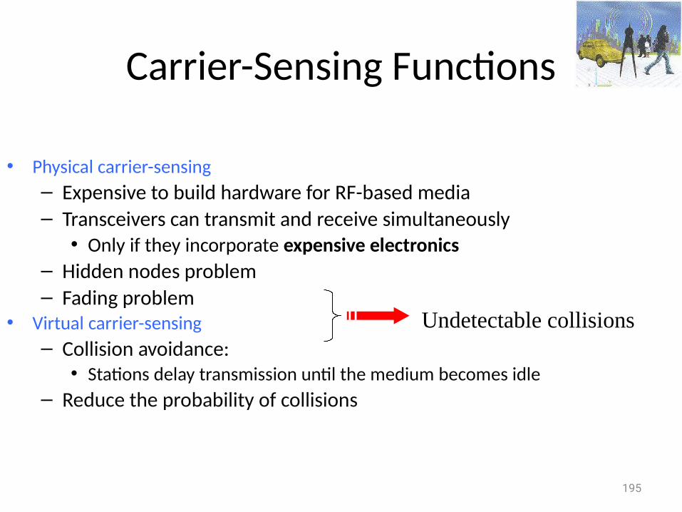
Carrier-Sensing Functions
• Physical carrier-sensing – Expensive to build hardware for RF-based media– Transceivers can transmit and receive simultaneously
• Only if they incorporate expensive electronics – Hidden nodes problem– Fading problem
• Virtual carrier-sensing– Collision avoidance:
• Stations delay transmission until the medium becomes idle– Reduce the probability of collisions
Undetectable collisions
Next ….
• We will talk more about IEEE802.11 MAC and then about performance issues of
wireless networks …
196
Top Related