


γλώσσες
Σελίδες
Νομικός

1
Ravi Sundaram
Cengrs Geotechnica Pvt. Ltd.Noida
A-100 Sector 63, NoidaPh: (O): 0120-42067111 (M): 9810538095
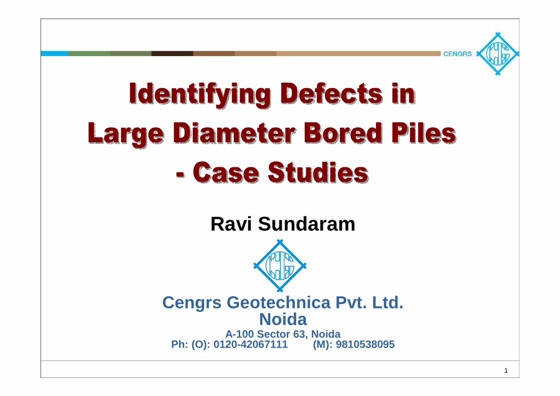
What makes a “Good Pile”?To perform successfully, a pile
should:
•• Have adequate soil resistanceHave adequate soil resistance
•• Be structurally soundBe structurally sound
These are two separate requirements both must be satisfied
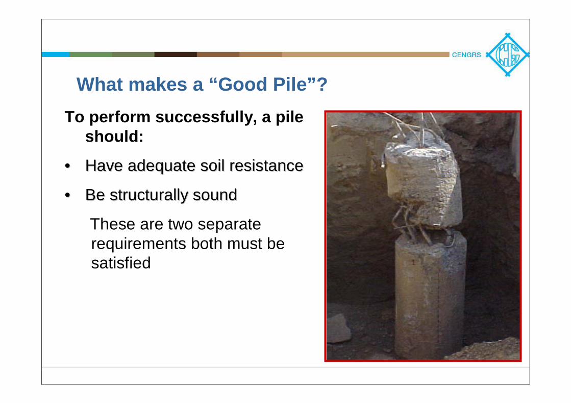
Assess Loads
Site Investigation
Select Pile Type
SPT, Cone, Pressuremeter
Estimate Pile Length
ExperienceAvailable EquipmentEnvironment
Quality Assurance of FoundationsQuality Assurance of Foundations-- Design AspectsDesign Aspects
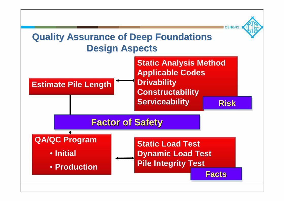
Estimate Pile Length
QA/QC Program• Initial• Production
Static Analysis MethodApplicable CodesDrivabilityConstructabilityServiceability
Static Load TestDynamic Load TestPile Integrity Test
Factor of SafetyFactor of SafetyFactor of Safety
RiskRiskRisk
FactsFactsFacts
Quality Assurance of Deep Foundations Quality Assurance of Deep Foundations Design AspectsDesign Aspects

On most sites, the reality is quite different
Bored Pile Quality: Do the piles Always look Bored Pile Quality: Do the piles Always look like this?like this?
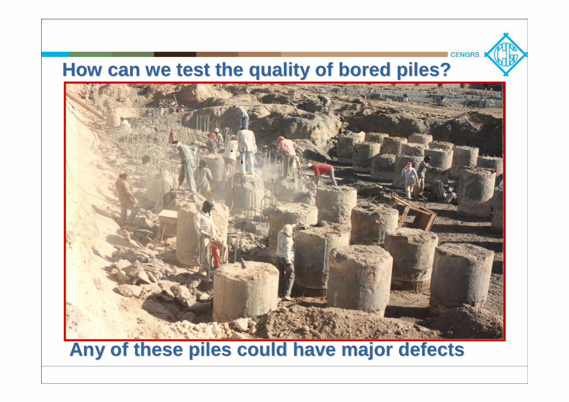
How can we test the quality of bored piles?How can we test the quality of bored piles?
Any of these piles could have major defectsAny of these piles could have major defects
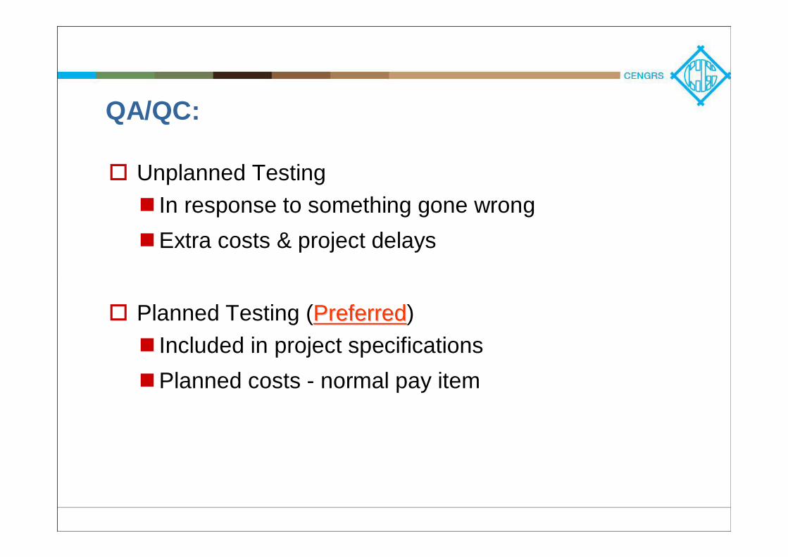
QA/QC:
Unplanned TestingIn response to something gone wrongExtra costs & project delays
Planned Testing (PreferredPreferred)Included in project specificationsPlanned costs - normal pay item
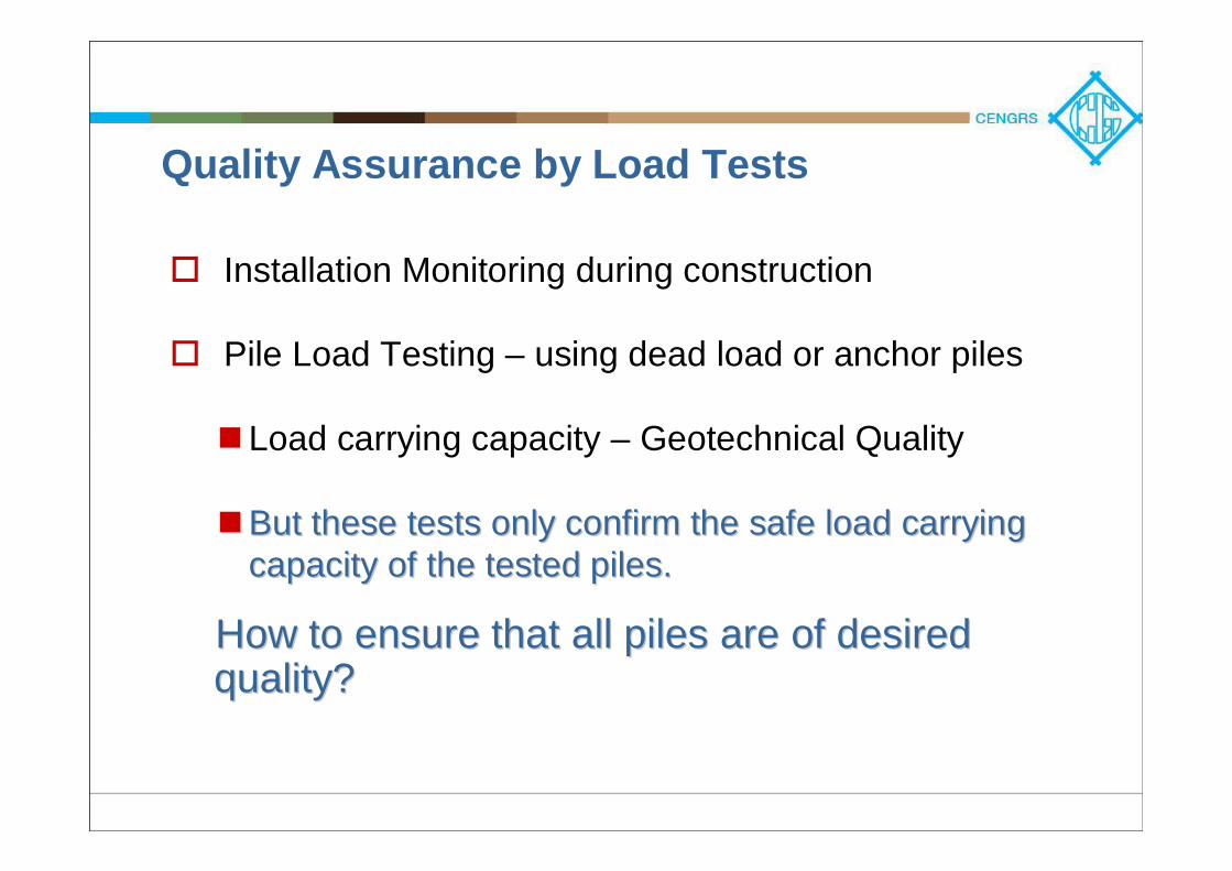
Quality Assurance by Load Tests
Installation Monitoring during construction
Pile Load Testing – using dead load or anchor piles
Load carrying capacity – Geotechnical Quality
But these tests only confirm the safe load carrying But these tests only confirm the safe load carrying capacity of the tested piles.capacity of the tested piles.
How to ensure that all piles are of desired How to ensure that all piles are of desired quality?quality?
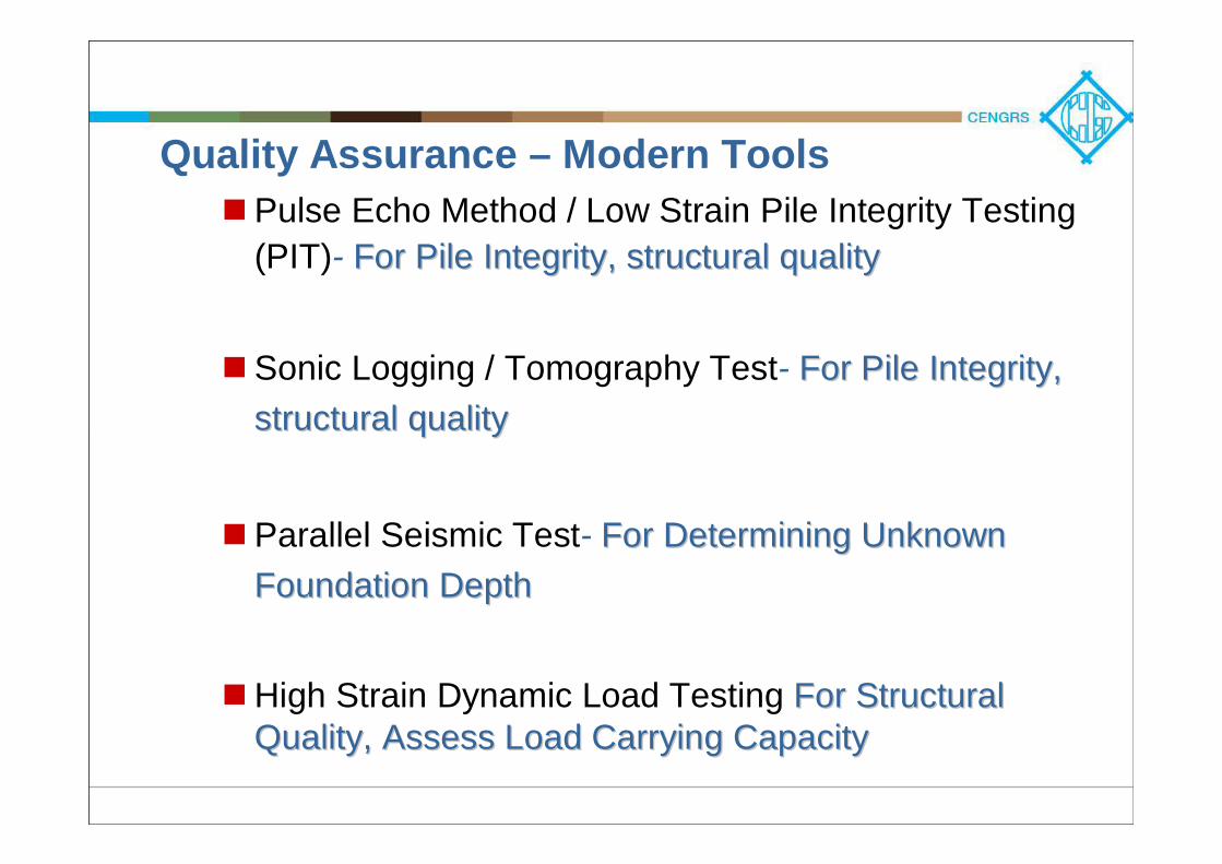
Quality Assurance – Modern ToolsPulse Echo Method / Low Strain Pile Integrity Testing (PIT)- For Pile Integrity, structural qualityFor Pile Integrity, structural quality
Sonic Logging / Tomography Test- For Pile Integrity, For Pile Integrity, structural qualitystructural quality
Parallel Seismic Test- For Determining Unknown For Determining Unknown Foundation DepthFoundation Depth
High Strain Dynamic Load Testing ForFor Structural Structural Quality, Assess Load Carrying CapacityQuality, Assess Load Carrying Capacity
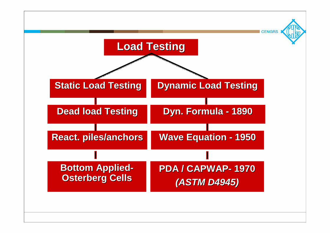
Load TestingLoad Testing
PDA / CAPWAPPDA / CAPWAP-- 19701970(ASTM D4945)(ASTM D4945)
Dynamic Load TestingDynamic Load Testing
Dyn. Formula Dyn. Formula -- 18901890
Wave Equation Wave Equation -- 19501950
Static Load TestingStatic Load Testing
Dead load TestingDead load Testing
React. piles/anchorsReact. piles/anchors
Bottom AppliedBottom Applied--OsterbergOsterberg CellsCells
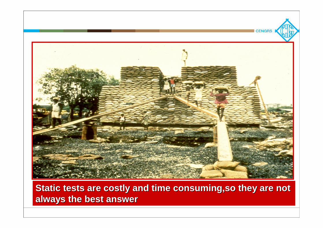
Static tests are costly and time consuming,so they are not Static tests are costly and time consuming,so they are not always the best answeralways the best answer
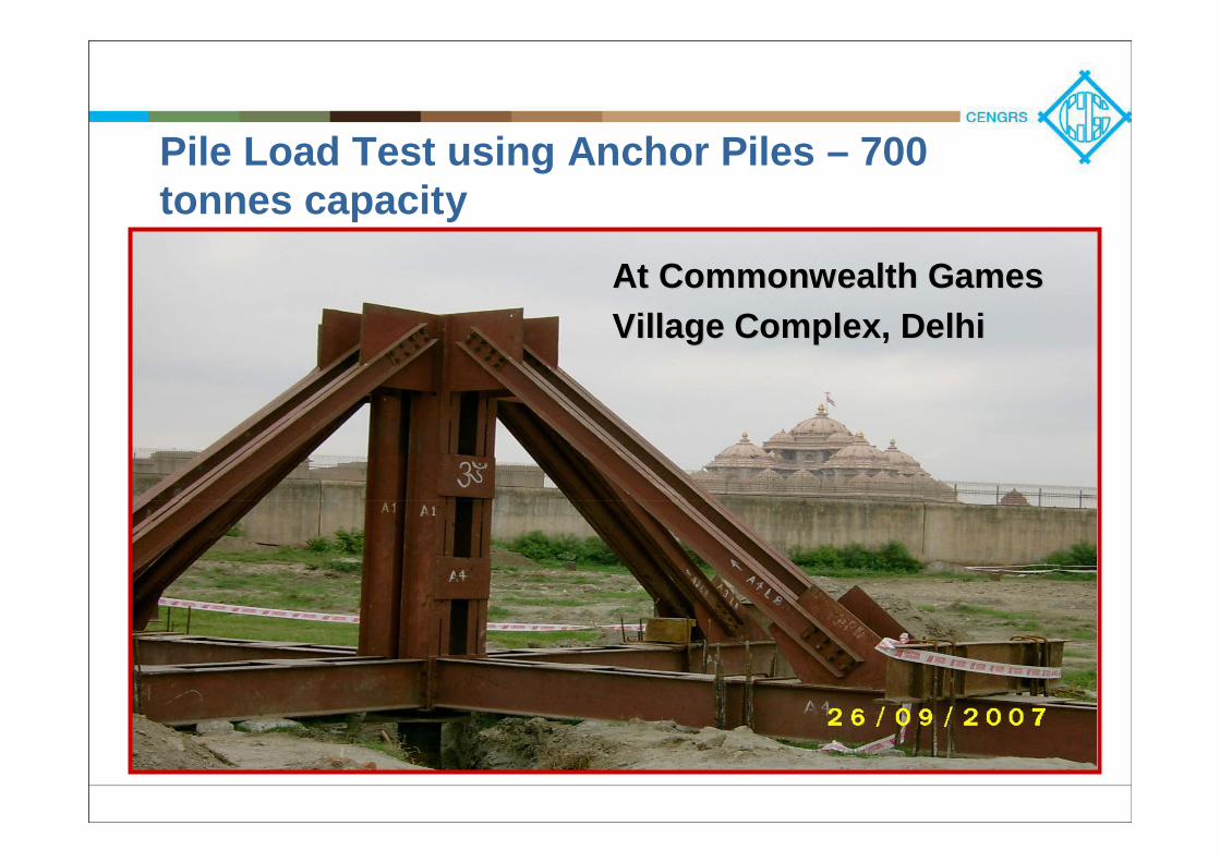
Pile Load Test using Anchor Piles – 700 tonnes capacity
At Commonwealth GamesAt Commonwealth GamesVillage Complex, DelhiVillage Complex, Delhi

Low Strain Integrity MethodsPILE INTEGRITY TESTING (PIT)
Measure Pile Top Motion, Reflections from Defects
CROSS-HOLE SONIC LOGGING (CSL)
Determines Concrete Quality Between Tubes in Shaft
For large diameter bored piles
PARALLEL SEISMIC (PS)
Hit Pile, Measure Hydrophone in Parallel Tube
Determines only Pile Length
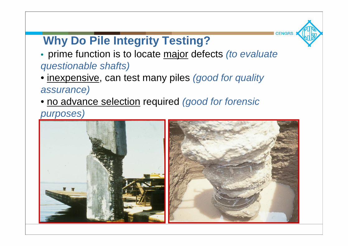
Why Do Pile Integrity Testing?• prime function is to locate major defects (to evaluate questionable shafts)• inexpensive, can test many piles (good for quality assurance)• no advance selection required (good for forensic purposes)
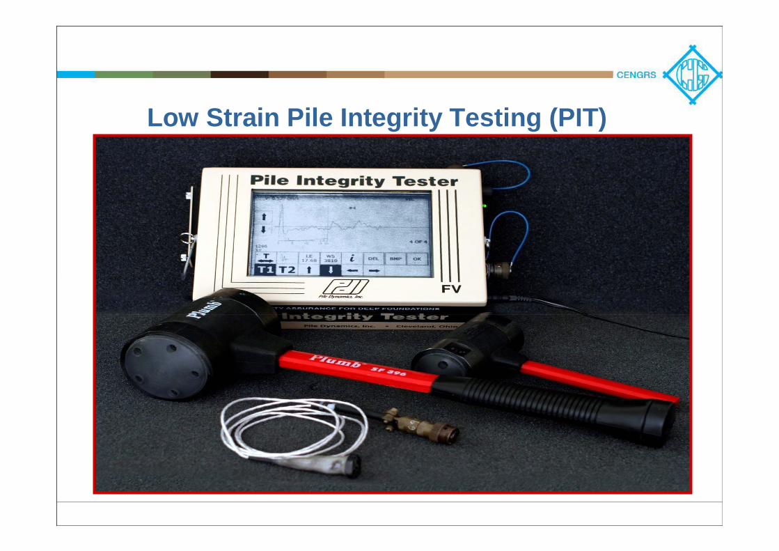
Low Strain Pile Integrity Testing (PIT)
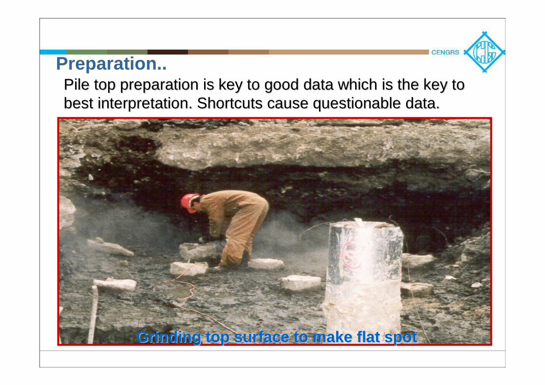
Grinding top surface to make flat spotGrinding top surface to make flat spot
Pile top preparation is key to good data which is the key to Pile top preparation is key to good data which is the key to best interpretation. Shortcuts cause questionable data.best interpretation. Shortcuts cause questionable data.
Preparation..
FF
ΔΔLL
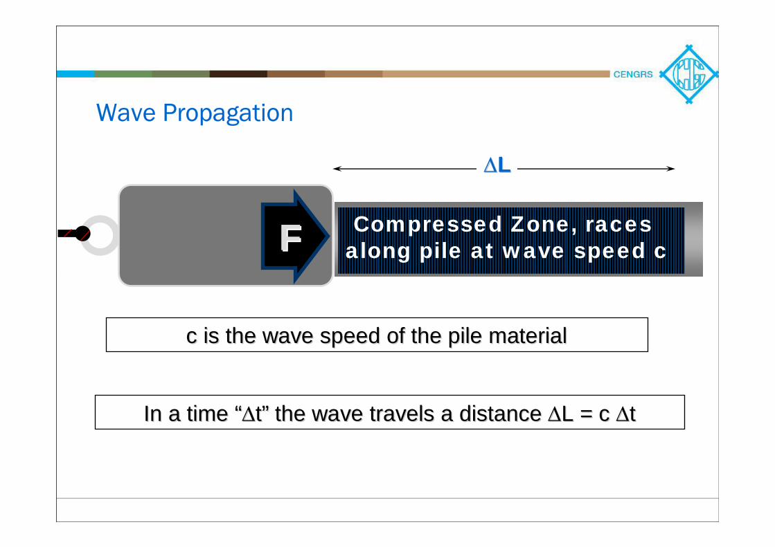
Compressed Zone, racesalong pile at wave speed c
c is the wave speed of the pile material c is the wave speed of the pile material
In a time In a time ““ΔΔtt”” the wave travels a distance the wave travels a distance ΔΔL = c L = c ΔΔtt
Wave Propagation
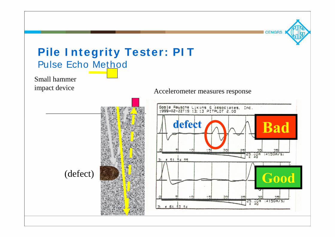
Pile Integrity Tester: PITPulse Echo Method
Accelerometer measures response
defectdefect
Good
Bad
Small hammer impact device
(defect)
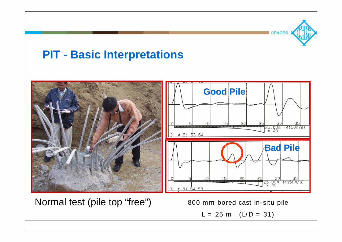
Good PileGood Pile
800 mm bored cast in-situ pile
L = 25 m (L/D = 31)
Bad PileBad Pile
Normal test (pile top “free”)
PIT - Basic Interpretations
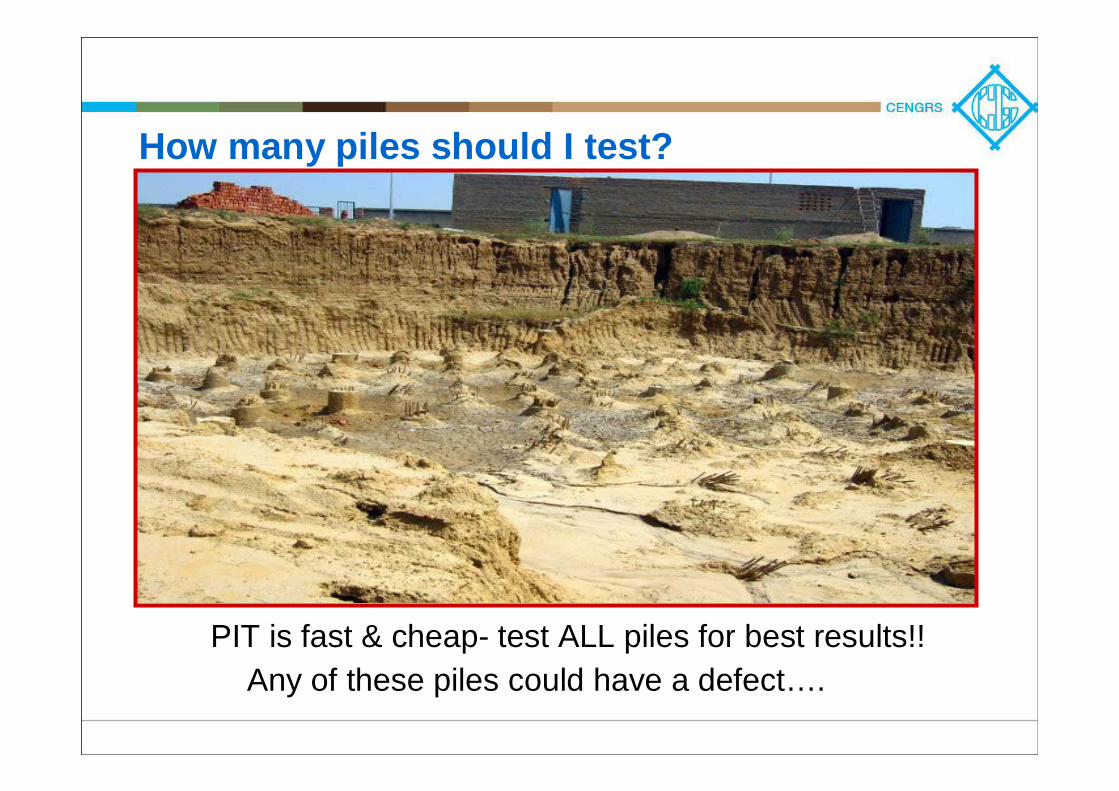
Any of these piles could have a defect….
How many piles should I test?
PIT is fast & cheap- test ALL piles for best results!!

PIT LimitationsAs per published literature, piles with L/D ratio upto
30 give reasonably good results
Highly non-uniform piles may be difficult to interpret
Cracks or mechanical joints block waves
Small defects or short length hard to find
Not always applicable: inconsistent or non-ideal
data may be difficult to interpret
No direct correlation to pile capacity; but can help to
identify which piles to load-test

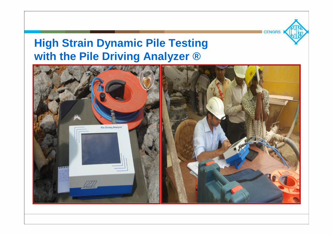
High Strain Dynamic Pile Testingwith the Pile Driving Analyzer ®
PDA Benefits to Project
•Confirms safe pile capacity
•Great savings in time and cost – test more piles at the
same cost, in less time
•Improves quality assurancePDA can test piles to reduce costs and save PDA can test piles to reduce costs and save timetime
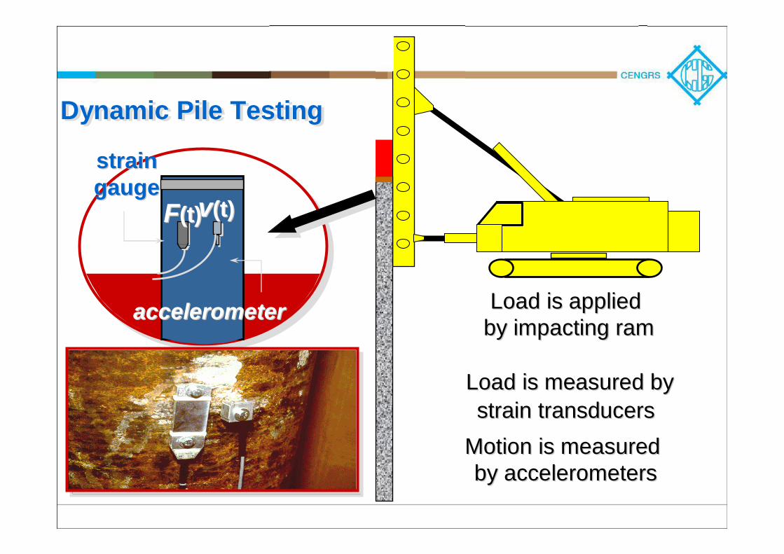
Motion is measured Motion is measured by accelerometersby accelerometers
strainstraingaugegauge
FF(t)(t)
accelerometeraccelerometer
vv(t(t))
Load is appliedLoad is appliedby impacting ramby impacting ram
Load is measured byLoad is measured bystrain transducersstrain transducers
Dynamic Pile TestingDynamic Pile Testing
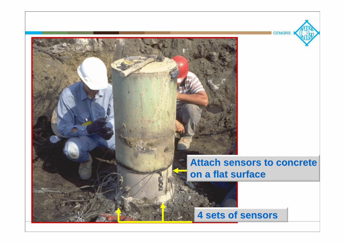
Attach sensors to concrete Attach sensors to concrete on a flat surfaceon a flat surface
4 sets of sensors4 sets of sensors
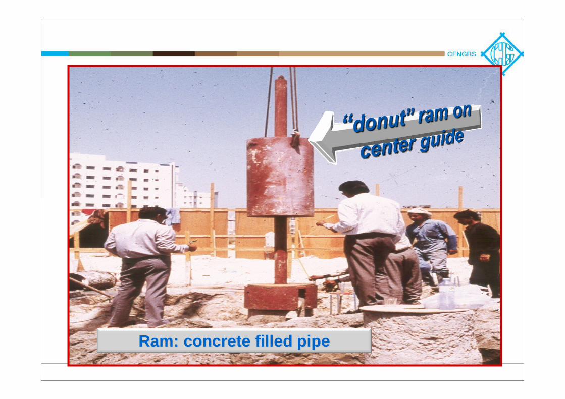
Ram: concrete filled pipeRam: concrete filled pipe

Dynamic Pile Monitoring
For each blow, determine:– Safe Pile Capacity– Pile Integrity– Pile Stresses– Hammer Performance
Last three items detect or prevent problems in the piles as-installed
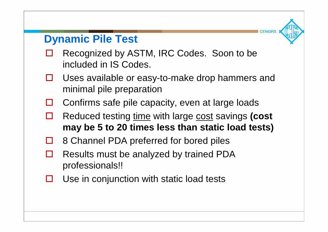
Dynamic Pile TestRecognized by ASTM, IRC Codes. Soon to be included in IS Codes. Uses available or easy-to-make drop hammers and minimal pile preparationConfirms safe pile capacity, even at large loadsReduced testing time with large cost savings (cost may be 5 to 20 times less than static load tests)8 Channel PDA preferred for bored pilesResults must be analyzed by trained PDA professionals!!Use in conjunction with static load tests
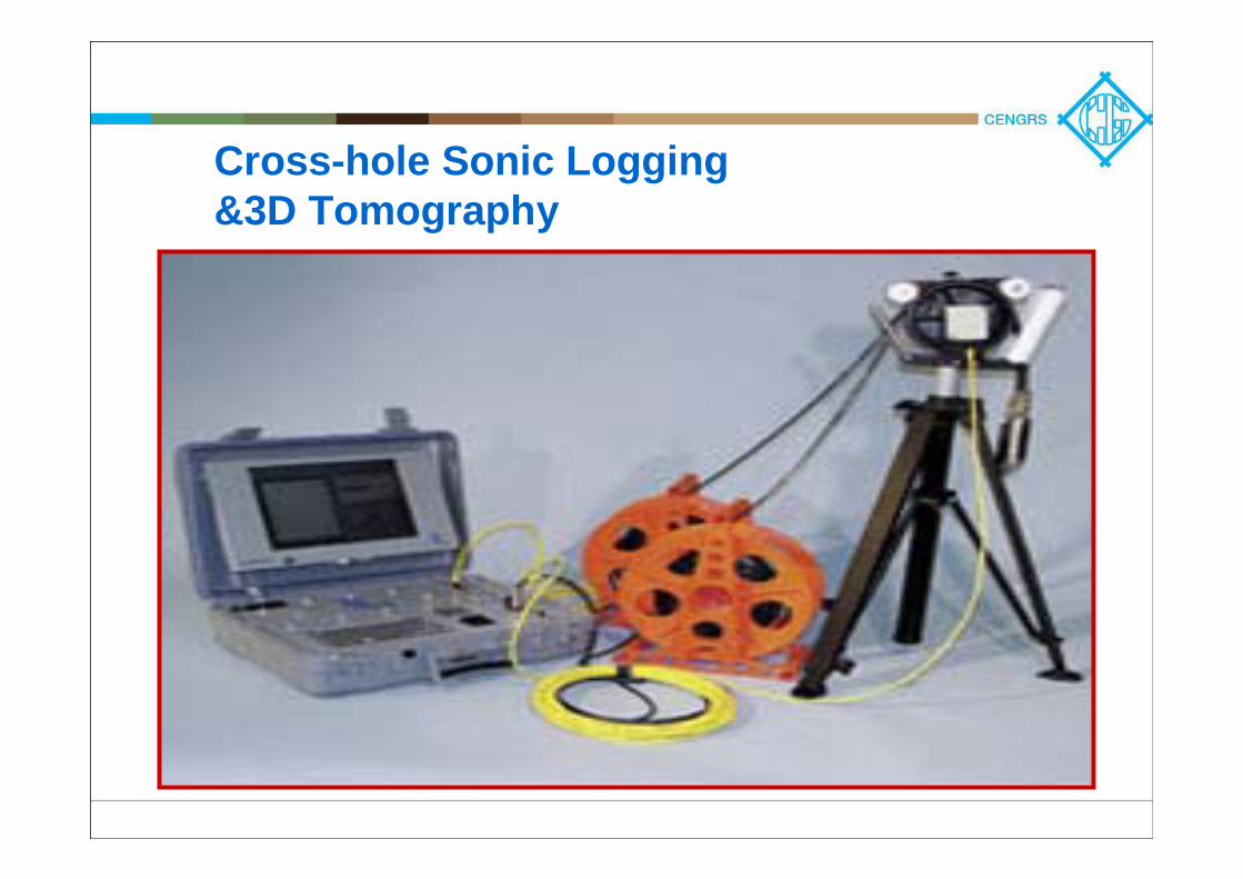
Cross-hole Sonic Logging&3D Tomography
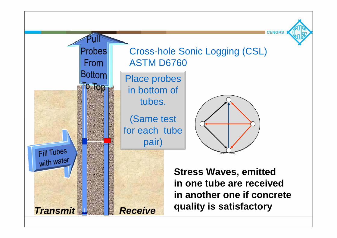
Cross-hole Sonic Logging (CSL)ASTM D6760
Stress Waves, emitted in one tube are receivedin another one if concretequality is satisfactoryTransmit Receive
Place probes in bottom of
tubes.
(Same test for each tube
pair)
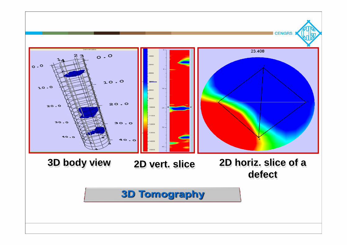
2D horiz. slice of a defect
2D horiz. slice of a defect
3D body view3D body view 2D vert. slice2D vert. slice
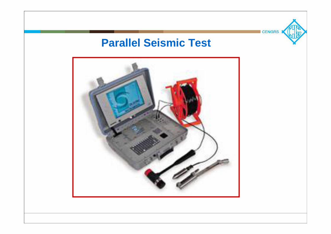
Parallel Seismic Test
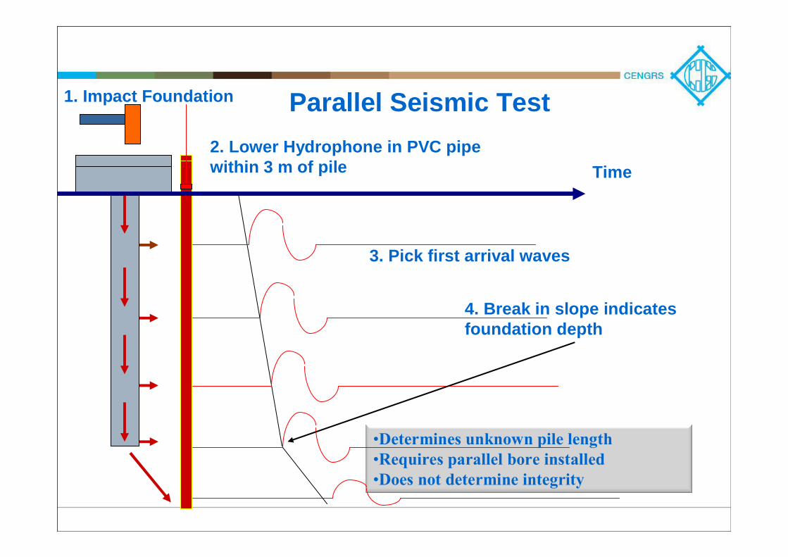
Parallel Seismic Test2. Lower Hydrophone in PVC pipe within 3 m of pile
•Determines unknown pile length •Requires parallel bore installed•Does not determine integrity
Time
1. Impact Foundation
3. Pick first arrival waves
4. Break in slope indicates foundation depth
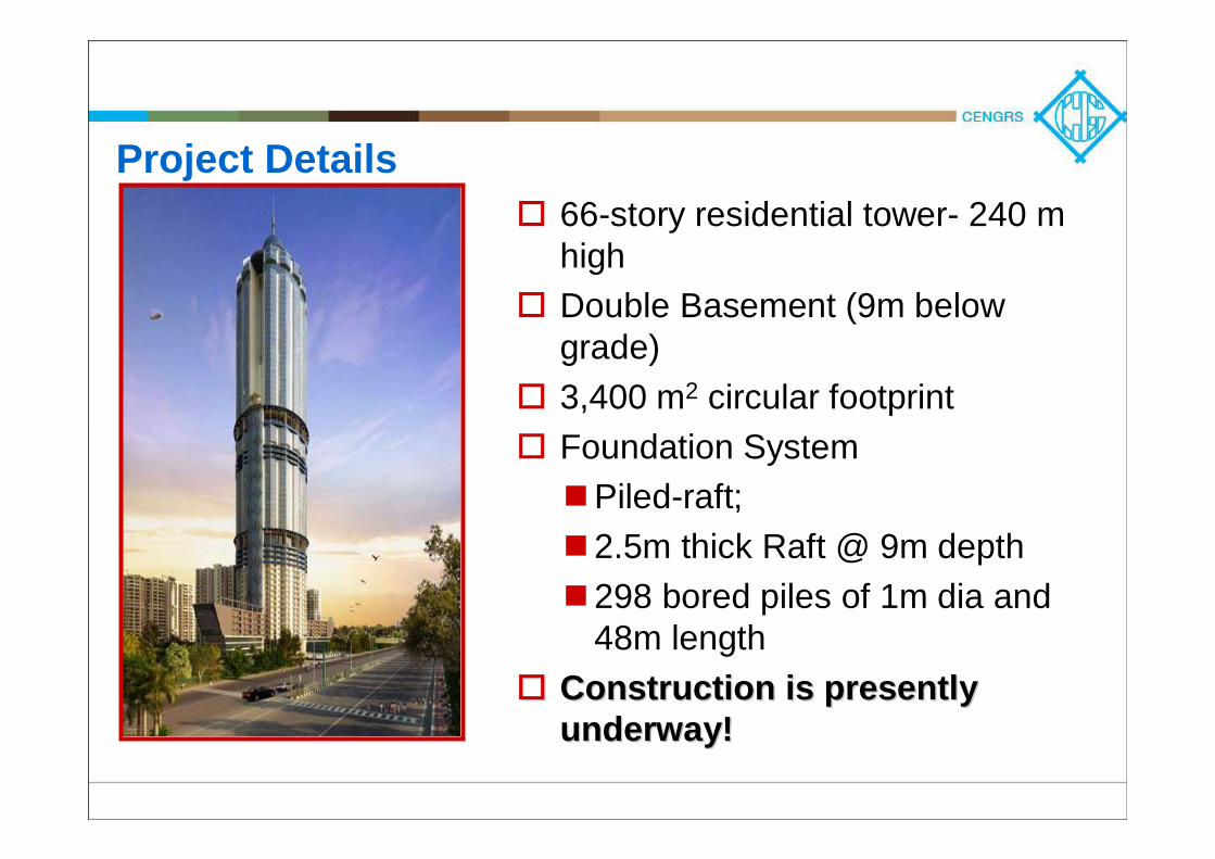
Project Details66-story residential tower- 240 m highDouble Basement (9m below grade)3,400 m2 circular footprintFoundation System
Piled-raft; 2.5m thick Raft @ 9m depth298 bored piles of 1m dia and 48m length
Construction is presently Construction is presently underway!underway!
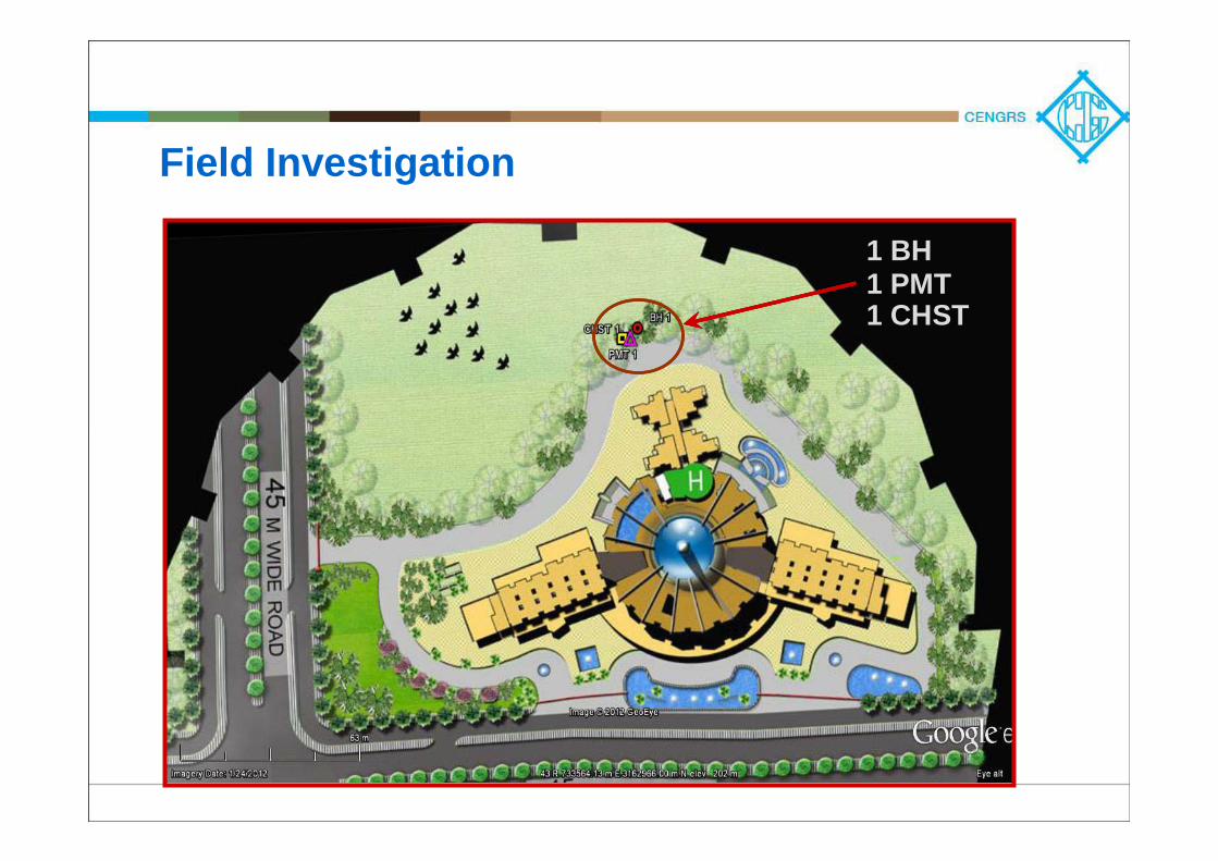
Field Investigation
1 BH1 PMT1 CHST
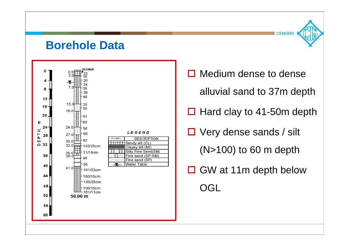
Borehole Data
Medium dense to dense
alluvial sand to 37m depth
Hard clay to 41-50m depth
Very dense sands / silt
(N>100) to 60 m depth
GW at 11m depth below
OGL
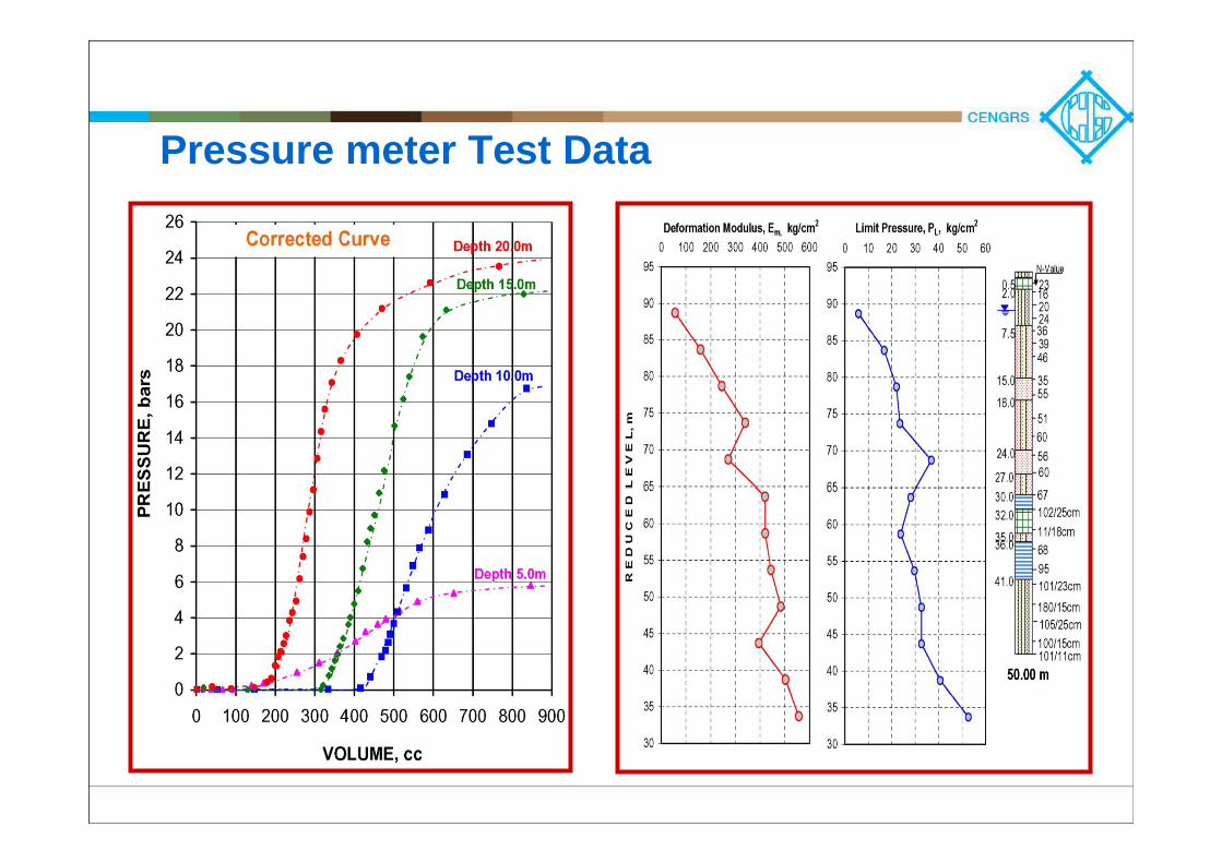
Pressure meter Test Data
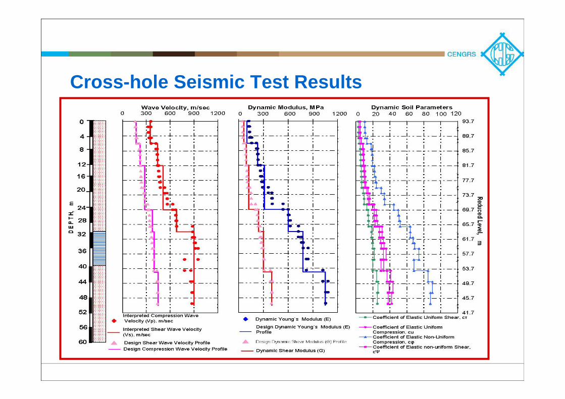
Cross-hole Seismic Test Results
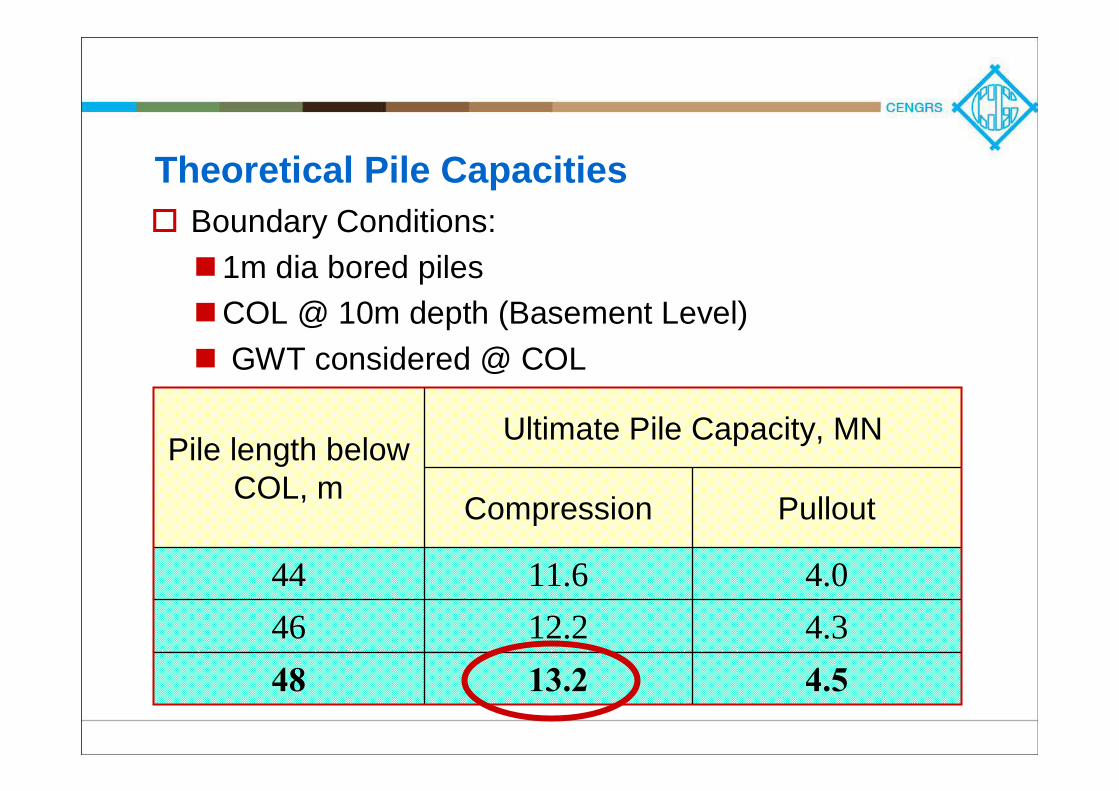
Theoretical Pile CapacitiesBoundary Conditions:
1m dia bored pilesCOL @ 10m depth (Basement Level)GWT considered @ COL
Pile length below COL, m
Ultimate Pile Capacity, MN
Compression Pullout
44 11.6 4.046 12.2 4.348 13.2 4.5
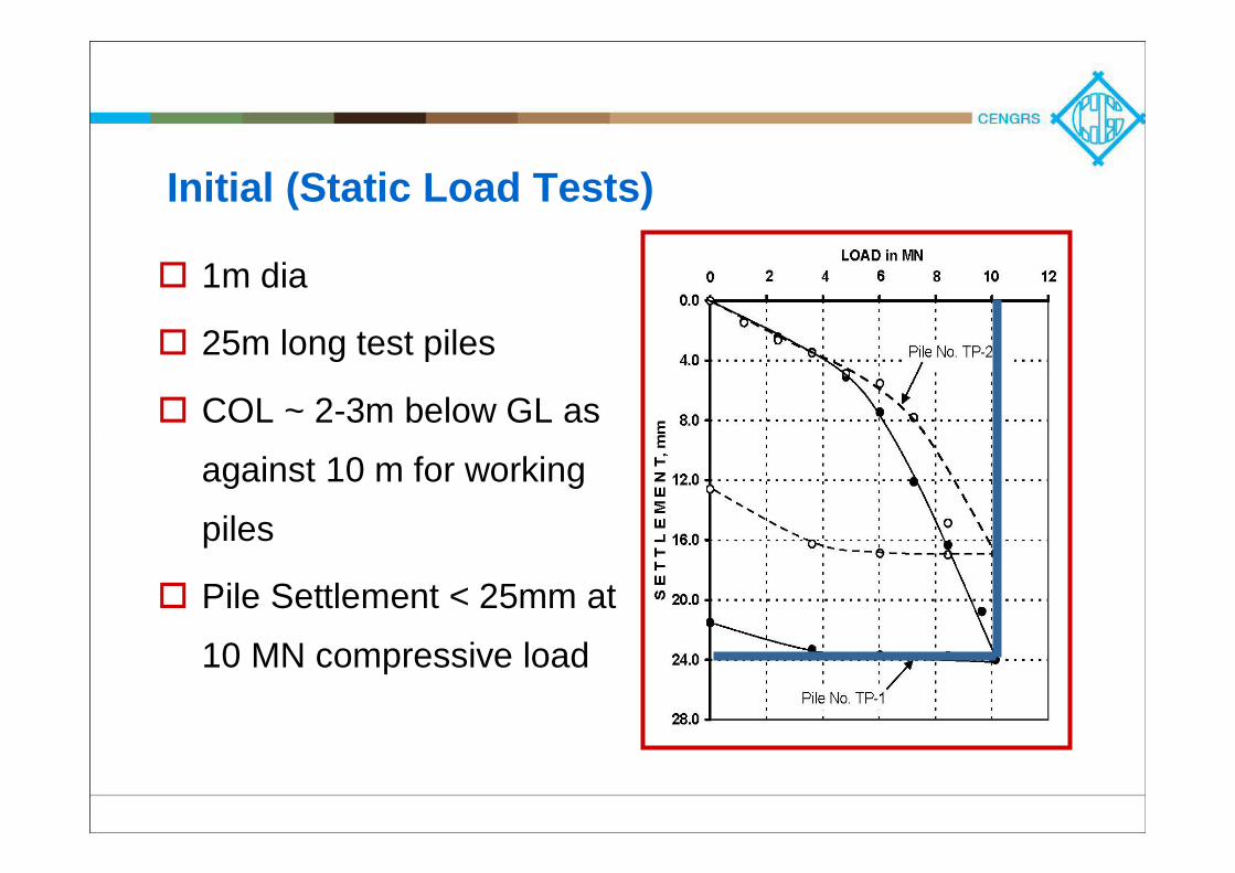
Initial (Static Load Tests)
1m dia
25m long test piles
COL ~ 2-3m below GL as
against 10 m for working
piles
Pile Settlement < 25mm at
10 MN compressive load
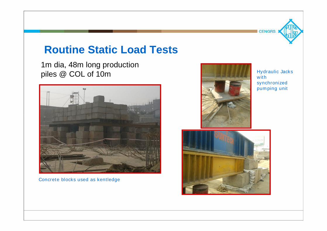
Routine Static Load Tests
Concrete blocks used as kentledge
1m dia, 48m long production piles @ COL of 10m Hydraulic Jacks
with synchronized pumping unit
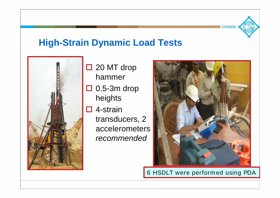
High-Strain Dynamic Load Tests
20 MT drop hammer0.5-3m drop heights4-strain transducers, 2 accelerometersrecommended
6 HSDLT were performed using PDA
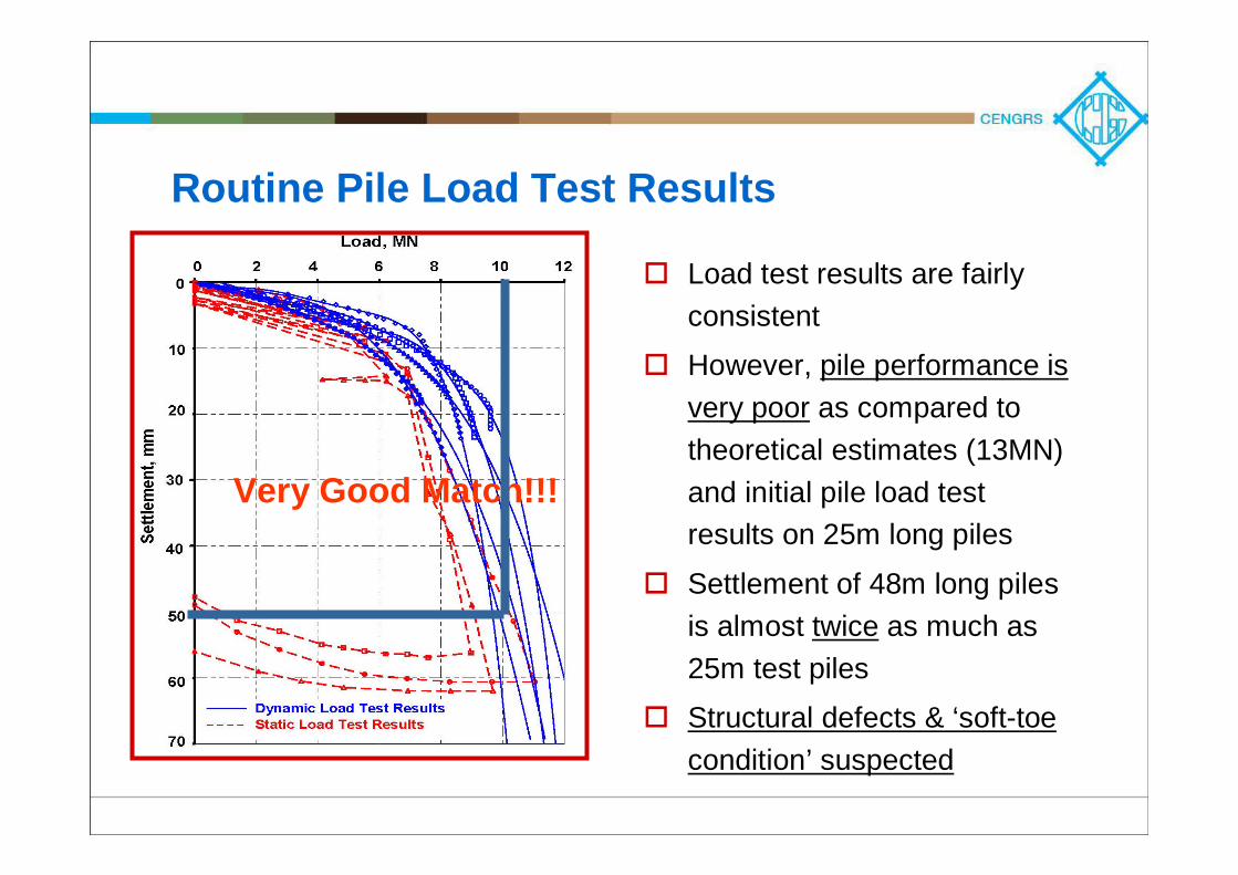
Routine Pile Load Test Results
Load test results are fairly consistent
However, pile performance is very poor as compared to theoretical estimates (13MN) and initial pile load test results on 25m long piles
Settlement of 48m long piles is almost twice as much as 25m test piles
Structural defects & ‘soft-toe condition’ suspected
Very Good Match!!!
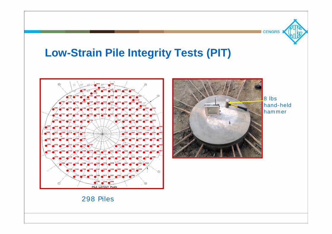
Low-Strain Pile Integrity Tests (PIT)
298 Piles
8 lbshand-held hammer
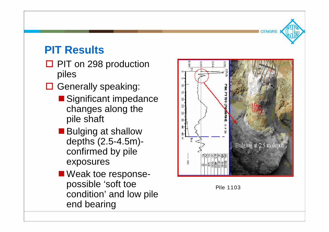
PIT ResultsPIT on 298 production pilesGenerally speaking:
Significant impedance changes along the pile shaftBulging at shallow depths (2.5-4.5m)-confirmed by pile exposuresWeak toe response-possible ‘soft toe condition’ and low pile end bearing
Pile 1103
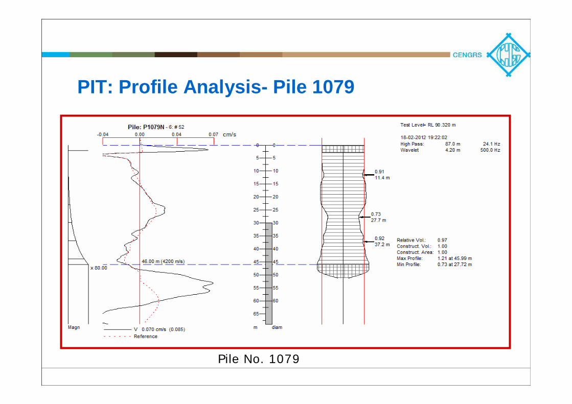
PIT: Profile Analysis- Pile 1079
Pile No. 1079
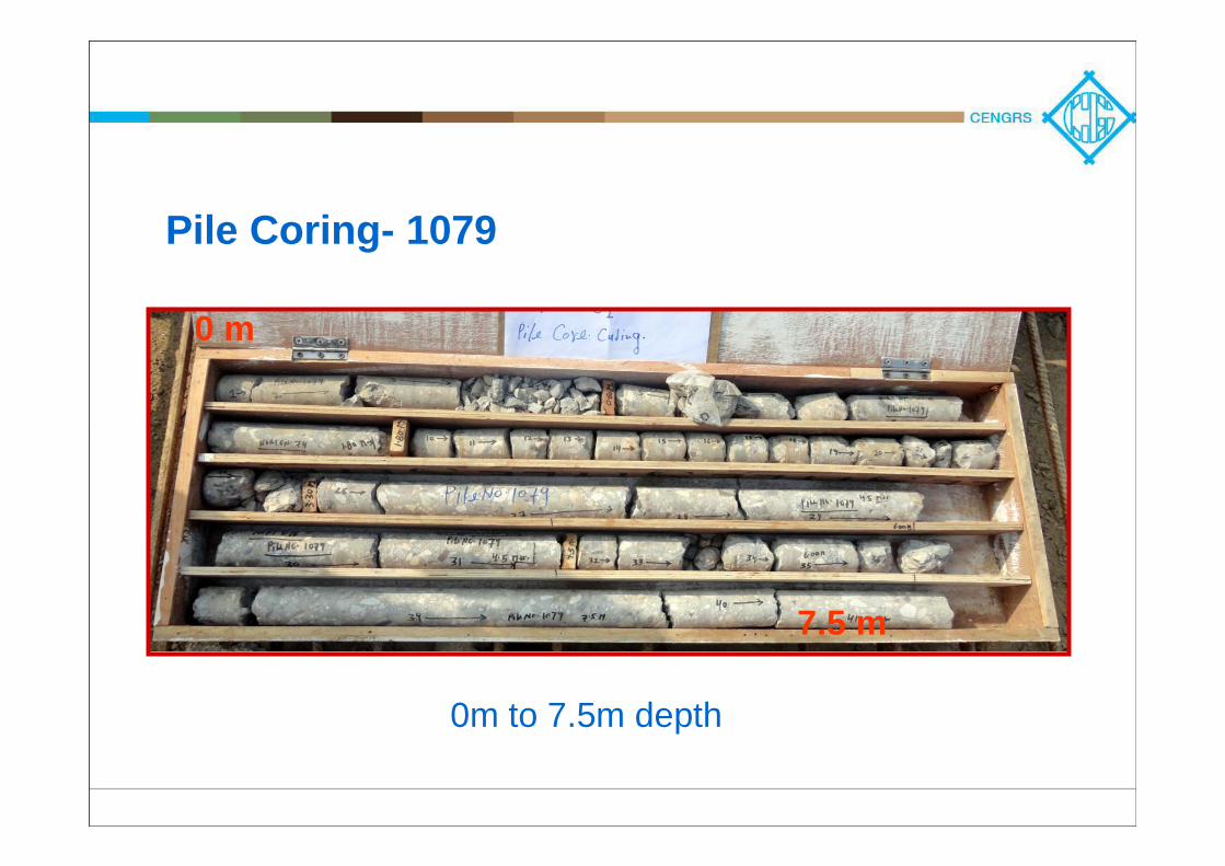
Pile Coring- 1079
0m to 7.5m depth
0 m
7.5 m
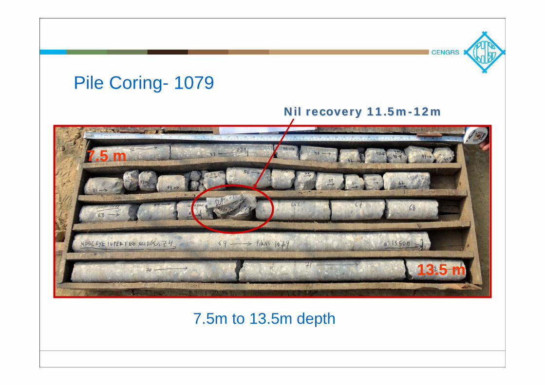
Pile Coring- 1079
7.5m to 13.5m depth
Nil recovery 11.5mNil recovery 11.5m--12m12m
7.5 m
13.5 m
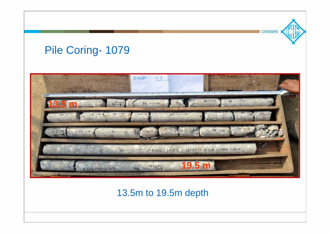
Pile Coring- 1079
13.5m to 19.5m depth
13.5 m
19.5 m
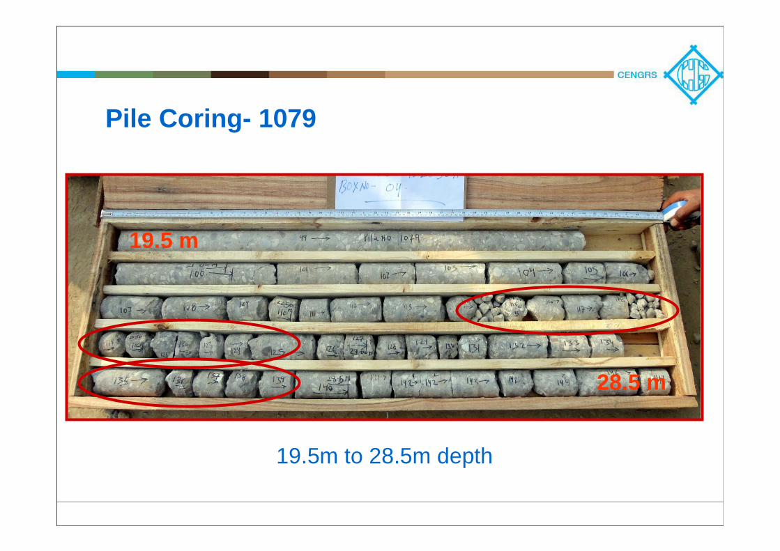
Pile Coring- 1079
19.5m to 28.5m depth
19.5 m
28.5 m
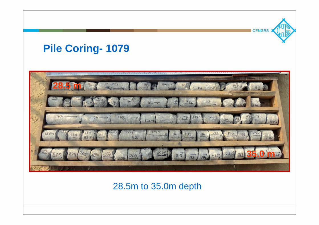
Pile Coring- 1079
28.5m to 35.0m depth
28.5 m
35.0 m
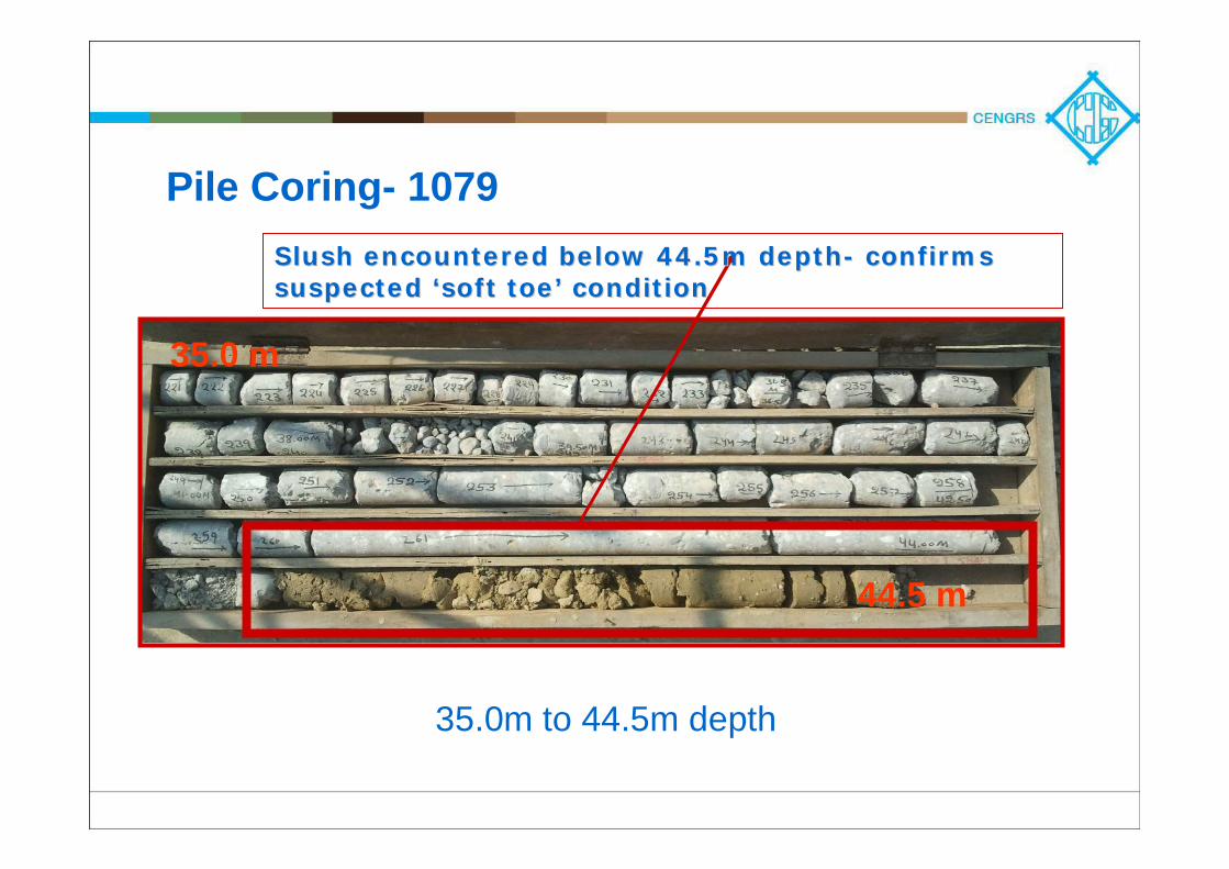
Pile Coring- 1079
35.0m to 44.5m depth
Slush encountered below 44.5m depthSlush encountered below 44.5m depth-- confirms confirms suspected suspected ‘‘soft toesoft toe’’ conditioncondition
35.0 m
44.5 m
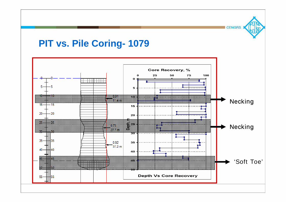
PIT vs. Pile Coring- 1079
NeckingNecking
‘Soft Toe’
NeckingNecking
Design Ramifications
Lowered pile stiffness was considered in the analysis
(nil end bearing)
Final design of the piled-raft system was updated with
reduced ultimate pile capacities / stiffness
Additional piles were constructed under the raft

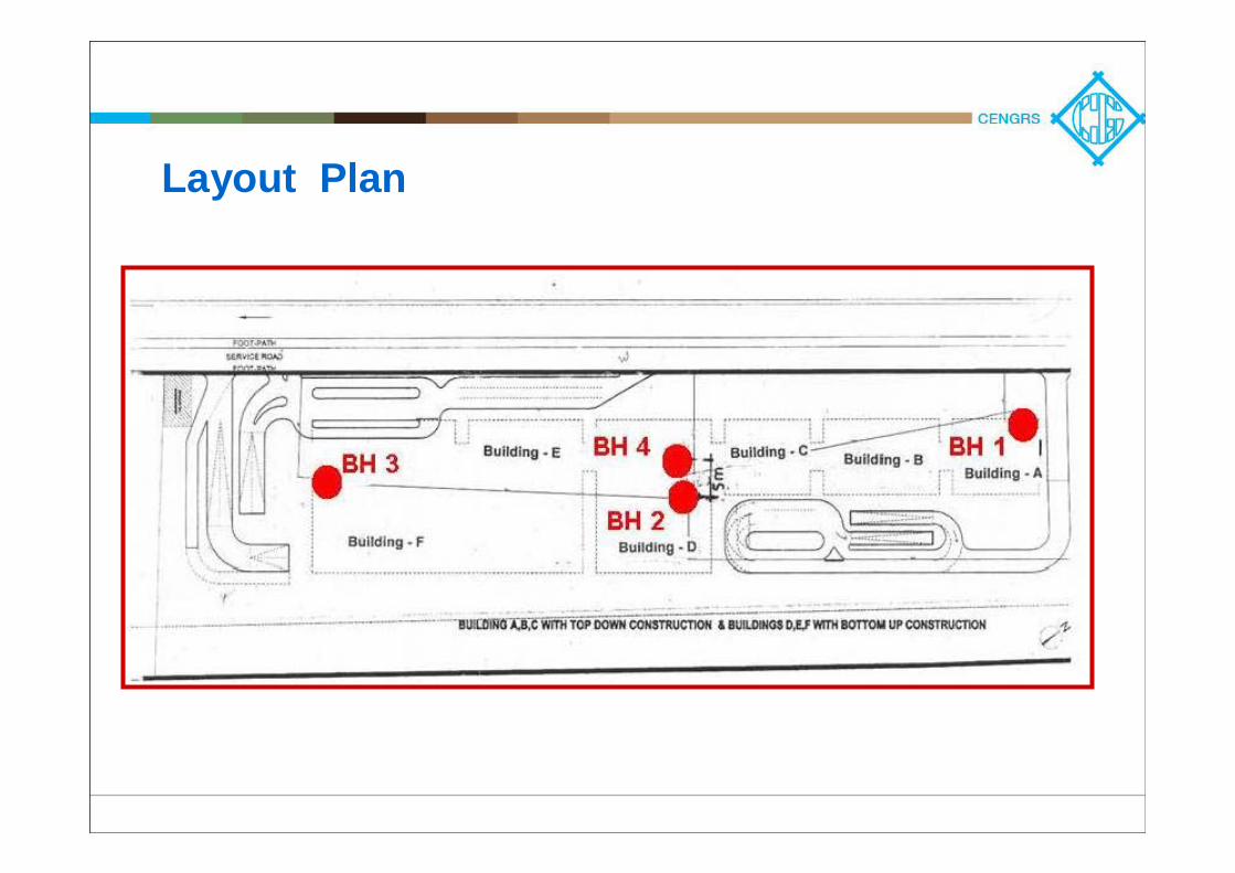
Layout Plan
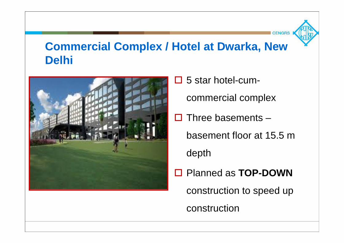
Commercial Complex / Hotel at Dwarka, New Delhi
5 star hotel-cum-
commercial complex
Three basements –
basement floor at 15.5 m
depth
Planned as TOP-DOWN
construction to speed up
construction
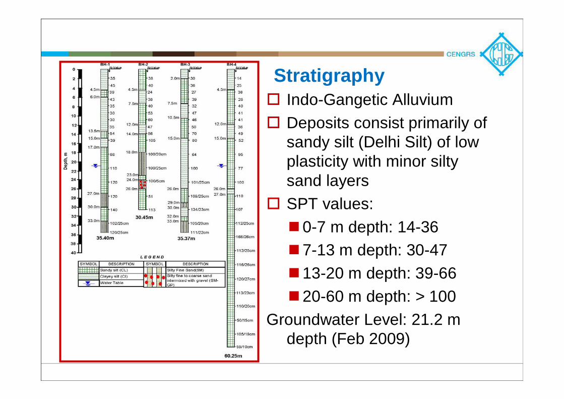
StratigraphyIndo-Gangetic AlluviumDeposits consist primarily of sandy silt (Delhi Silt) of low plasticity with minor siltysand layersSPT values:
0-7 m depth: 14-367-13 m depth: 30-4713-20 m depth: 39-6620-60 m depth: > 100
Groundwater Level: 21.2 m depth (Feb 2009)
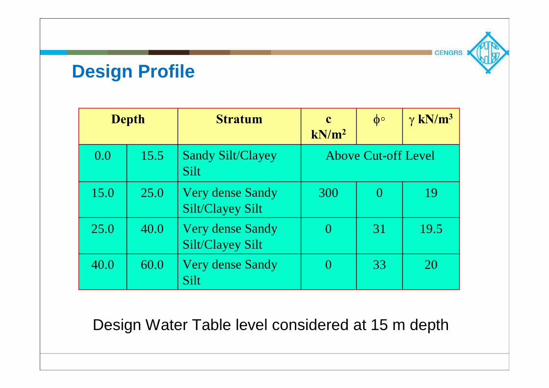
Design Profile
Depth Stratum ckN/m2
φ◦ γ kN/m3
0.0 15.5 Sandy Silt/Clayey Silt
Above Cut-off Level
15.0 25.0 Very dense Sandy Silt/Clayey Silt
300 0 19
25.0 40.0 Very dense Sandy Silt/Clayey Silt
0 31 19.5
40.0 60.0 Very dense Sandy Silt
0 33 20
Design Water Table level considered at 15 m depth
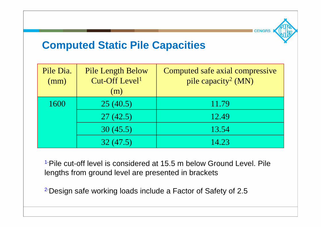
Computed Static Pile Capacities
Pile Dia. (mm)
Pile Length Below Cut-Off Level1
(m)
Computed safe axial compressive pile capacity2 (MN)
1600 25 (40.5) 11.7927 (42.5) 12.4930 (45.5) 13.5432 (47.5) 14.23
1-Pile cut-off level is considered at 15.5 m below Ground Level. Pile lengths from ground level are presented in brackets
2-Design safe working loads include a Factor of Safety of 2.5
Construction Sequence
Install 1600 mm diameter deep bored cast in-situ piles from ground levelAfter piles are installed, excavation for basement shall be taken upPortion of pile above basement level shall act as column, that below basement shall contribute to pile capacityConstruction of superstructure shall be taken up simultaneously
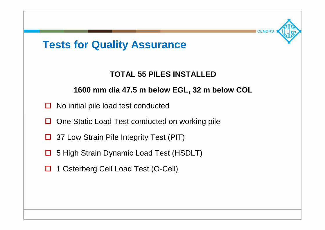
Tests for Quality Assurance
TOTAL 55 PILES INSTALLED
1600 mm dia 47.5 m below EGL, 32 m below COL
No initial pile load test conducted
One Static Load Test conducted on working pile
37 Low Strain Pile Integrity Test (PIT)
5 High Strain Dynamic Load Test (HSDLT)
1 Osterberg Cell Load Test (O-Cell)
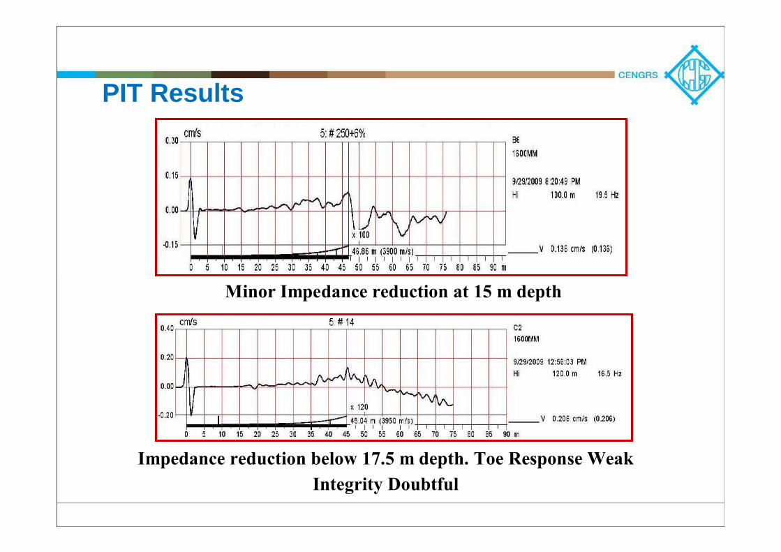
PIT Results
Minor Impedance reduction at 15 m depth
Impedance reduction below 17.5 m depth. Toe Response WeakIntegrity Doubtful
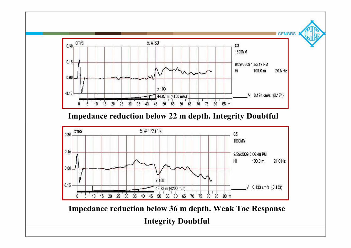
Impedance reduction below 36 m depth. Weak Toe ResponseIntegrity Doubtful
Impedance reduction below 22 m depth. Integrity Doubtful
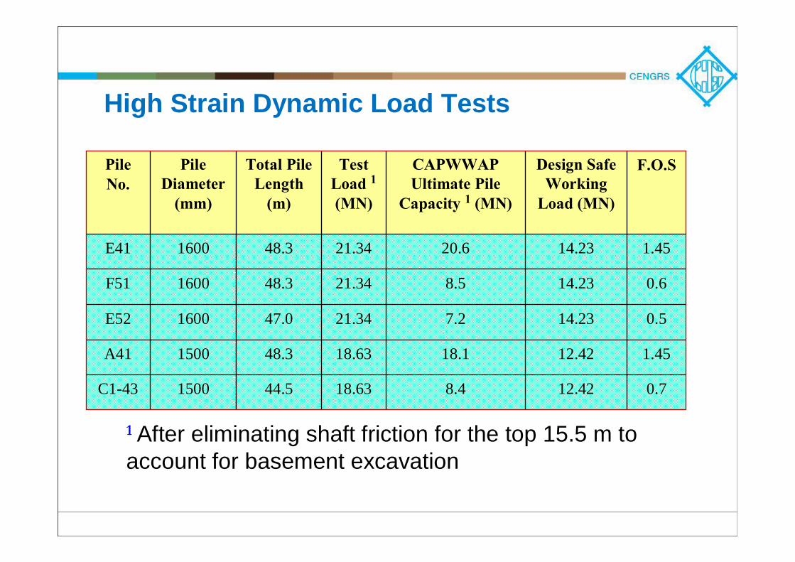
High Strain Dynamic Load Tests
Pile No.
Pile Diameter
(mm)
Total Pile Length
(m)
Test Load 1(MN)
CAPWWAPUltimate Pile
Capacity 1 (MN)
Design Safe Working
Load (MN)
F.O.S
E41 1600 48.3 21.34 20.6 14.23 1.45
F51 1600 48.3 21.34 8.5 14.23 0.6
E52 1600 47.0 21.34 7.2 14.23 0.5
A41 1500 48.3 18.63 18.1 12.42 1.45
C1-43 1500 44.5 18.63 8.4 12.42 0.7
1 After eliminating shaft friction for the top 15.5 m to account for basement excavation
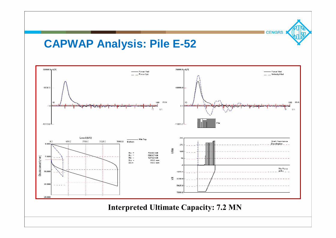
CAPWAP Analysis: Pile E-52
Interpreted Ultimate Capacity: 7.2 MN
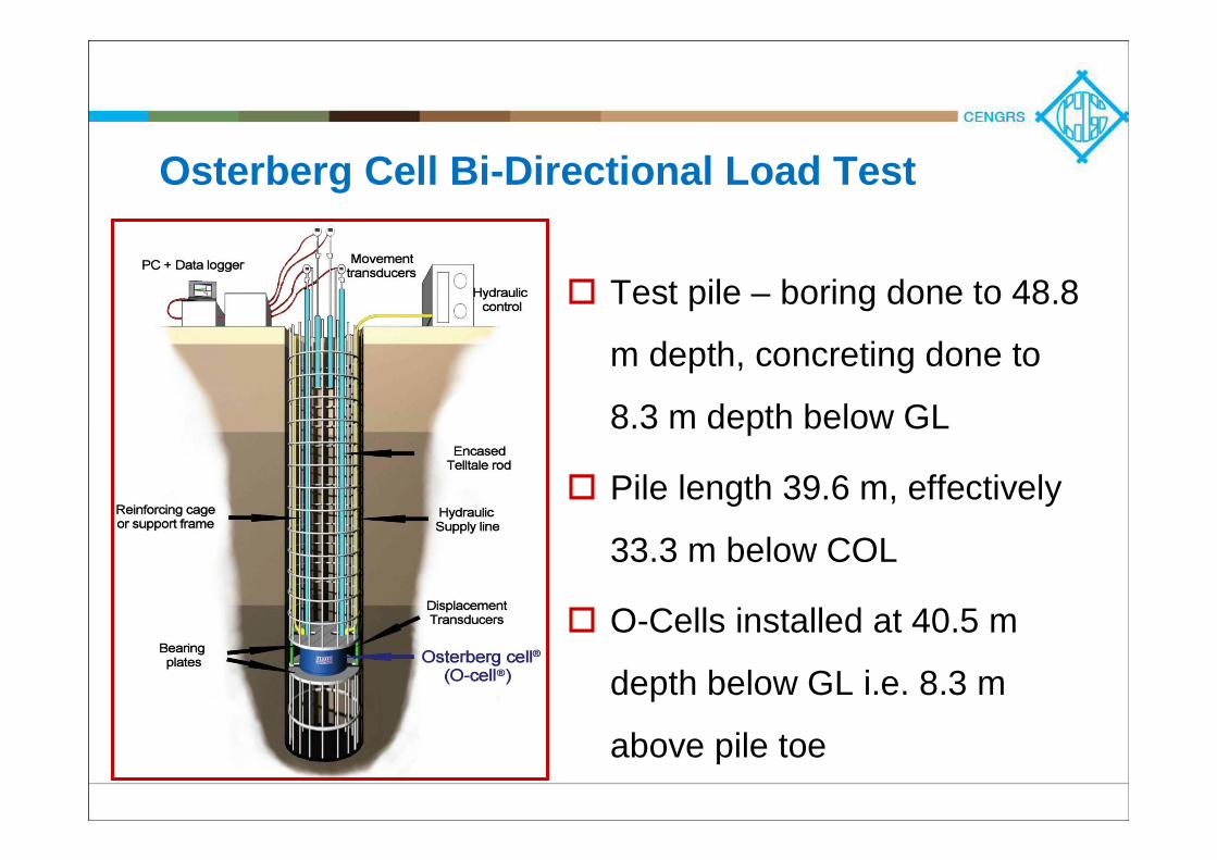
Osterberg Cell Bi-Directional Load Test
Test pile – boring done to 48.8
m depth, concreting done to
8.3 m depth below GL
Pile length 39.6 m, effectively
33.3 m below COL
O-Cells installed at 40.5 m
depth below GL i.e. 8.3 m
above pile toe
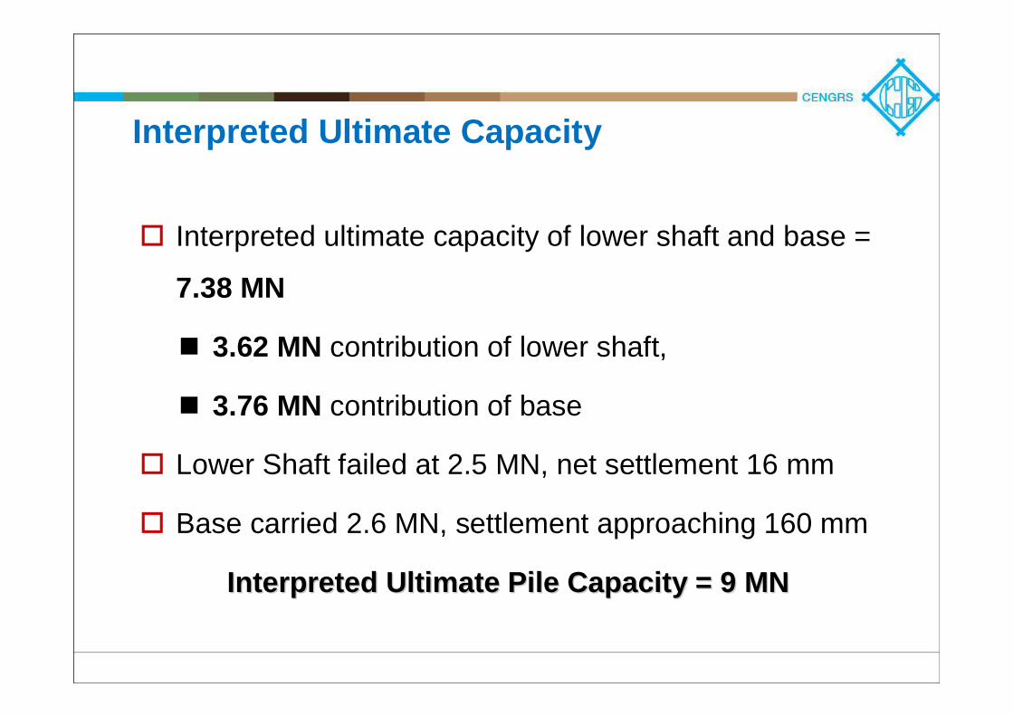
Interpreted Ultimate Capacity
Interpreted ultimate capacity of lower shaft and base =
7.38 MN
3.62 MN contribution of lower shaft,
3.76 MN contribution of base
Lower Shaft failed at 2.5 MN, net settlement 16 mm
Base carried 2.6 MN, settlement approaching 160 mm
Interpreted Ultimate Pile Capacity = 9 MNInterpreted Ultimate Pile Capacity = 9 MN
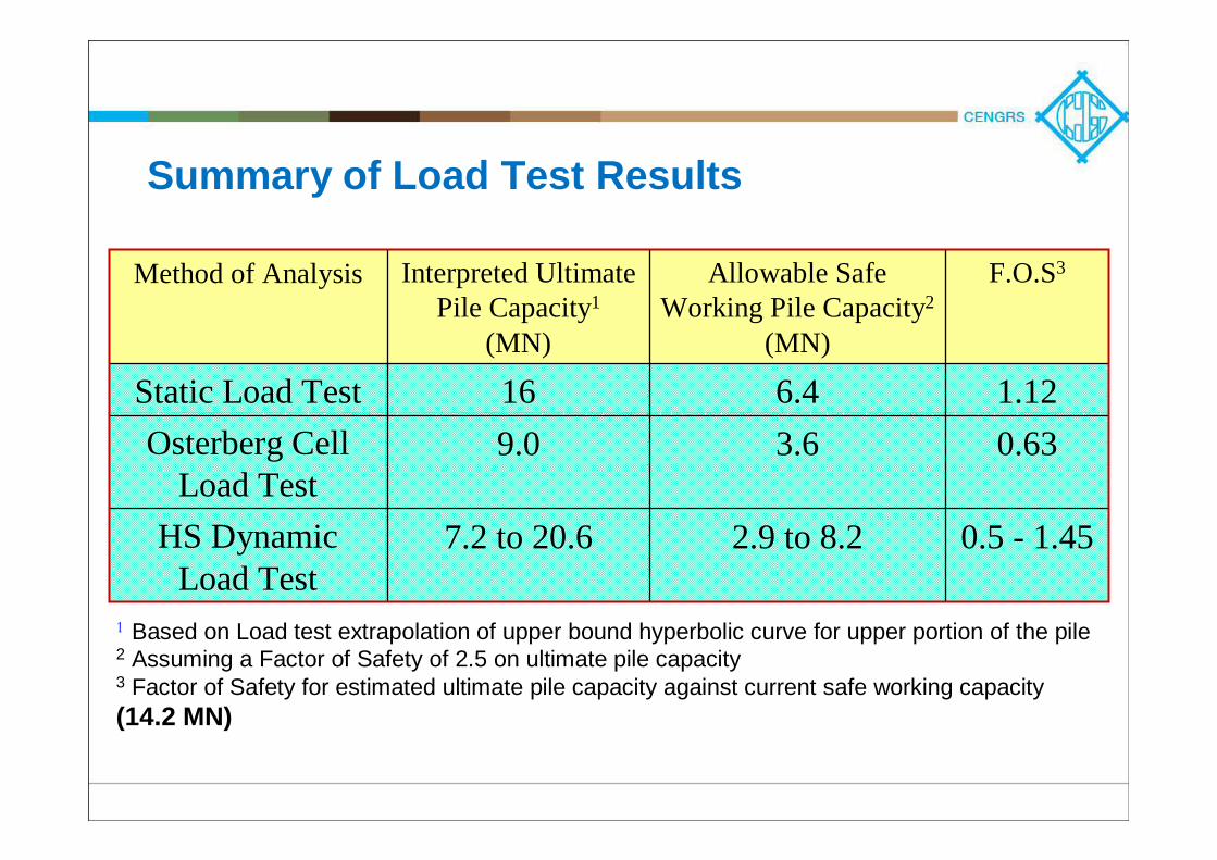
Summary of Load Test Results
Method of Analysis Interpreted Ultimate Pile Capacity1
(MN)
Allowable Safe Working Pile Capacity2
(MN)
F.O.S3
Static Load Test 16 6.4 1.12Osterberg Cell
Load Test9.0 3.6 0.63
HS Dynamic Load Test
7.2 to 20.6 2.9 to 8.2 0.5 - 1.45
1 Based on Load test extrapolation of upper bound hyperbolic curve for upper portion of the pile2 Assuming a Factor of Safety of 2.5 on ultimate pile capacity3 Factor of Safety for estimated ultimate pile capacity against current safe working capacity (14.2 MN)
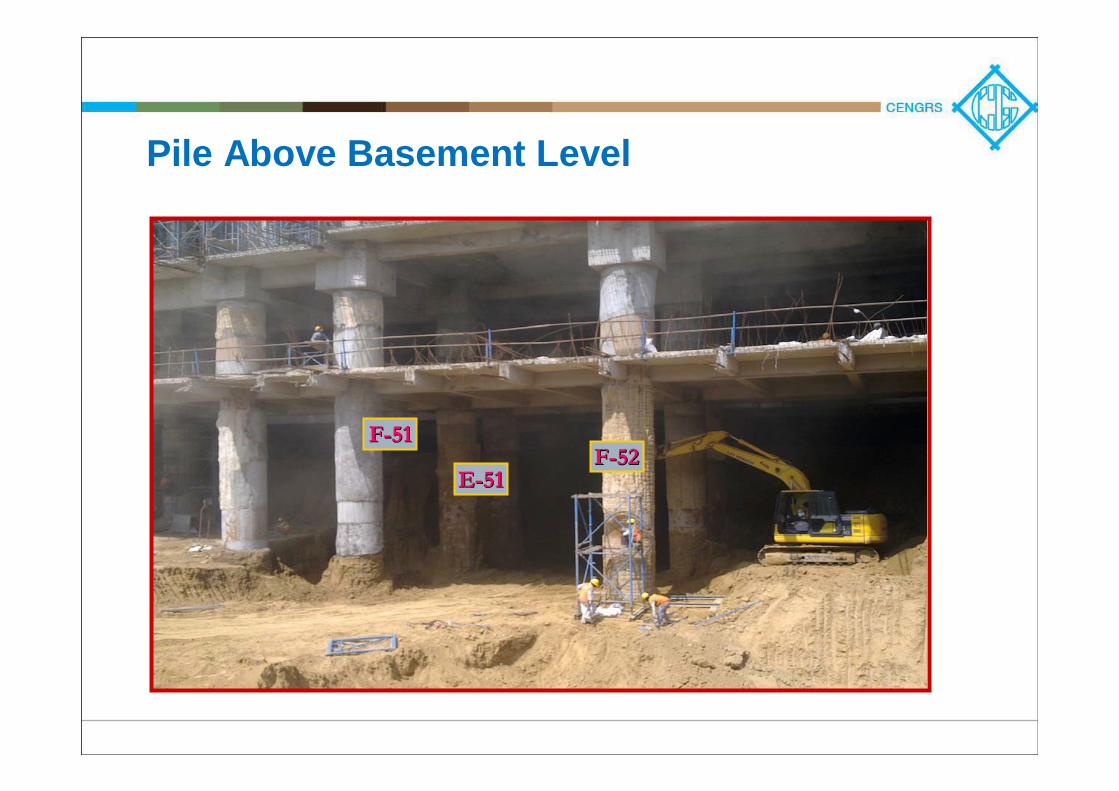
Pile Above Basement Level
FF--5151FF--5252
EE--5151
Quality of Piles Exposed above Basement Level
Pile diameter not uniform, substantial necking / bulging
observed in some piles
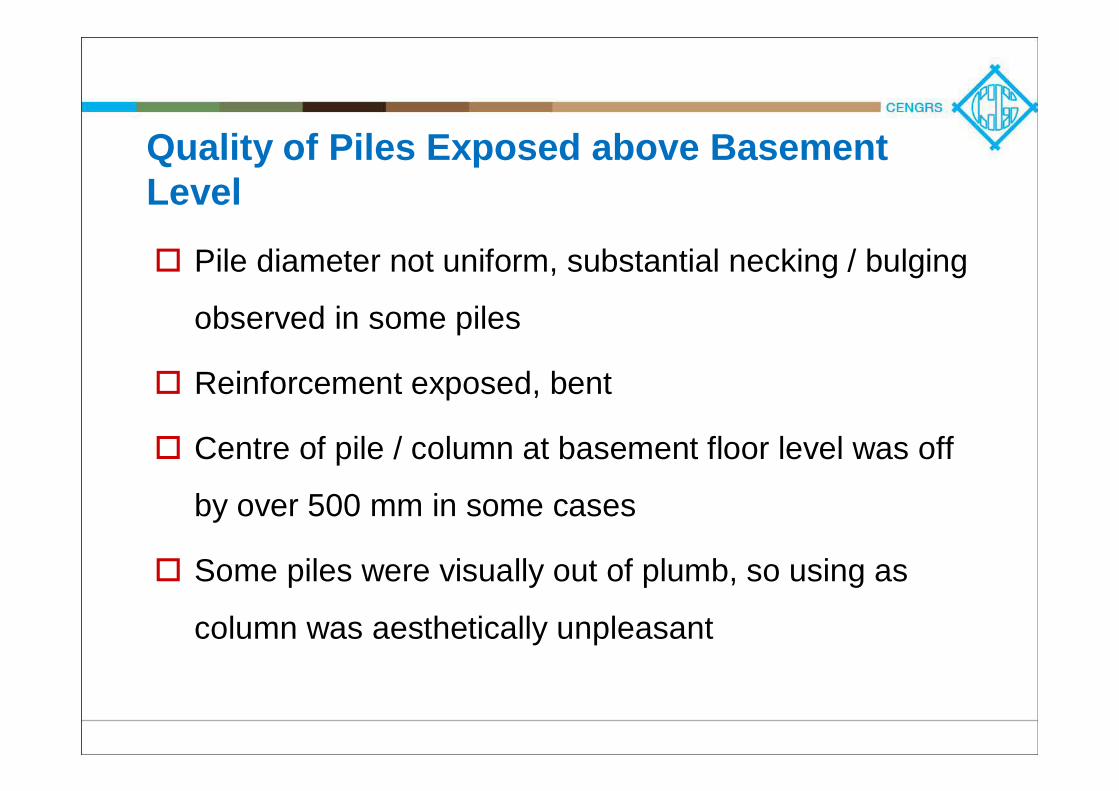
Reinforcement exposed, bent
Centre of pile / column at basement floor level was off
by over 500 mm in some cases
Some piles were visually out of plumb, so using as
column was aesthetically unpleasant
Reinforcement Exposed
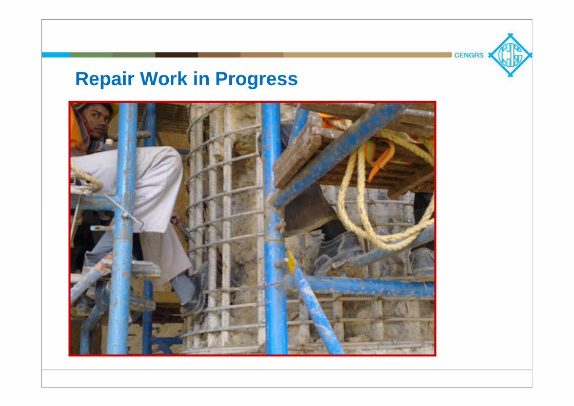
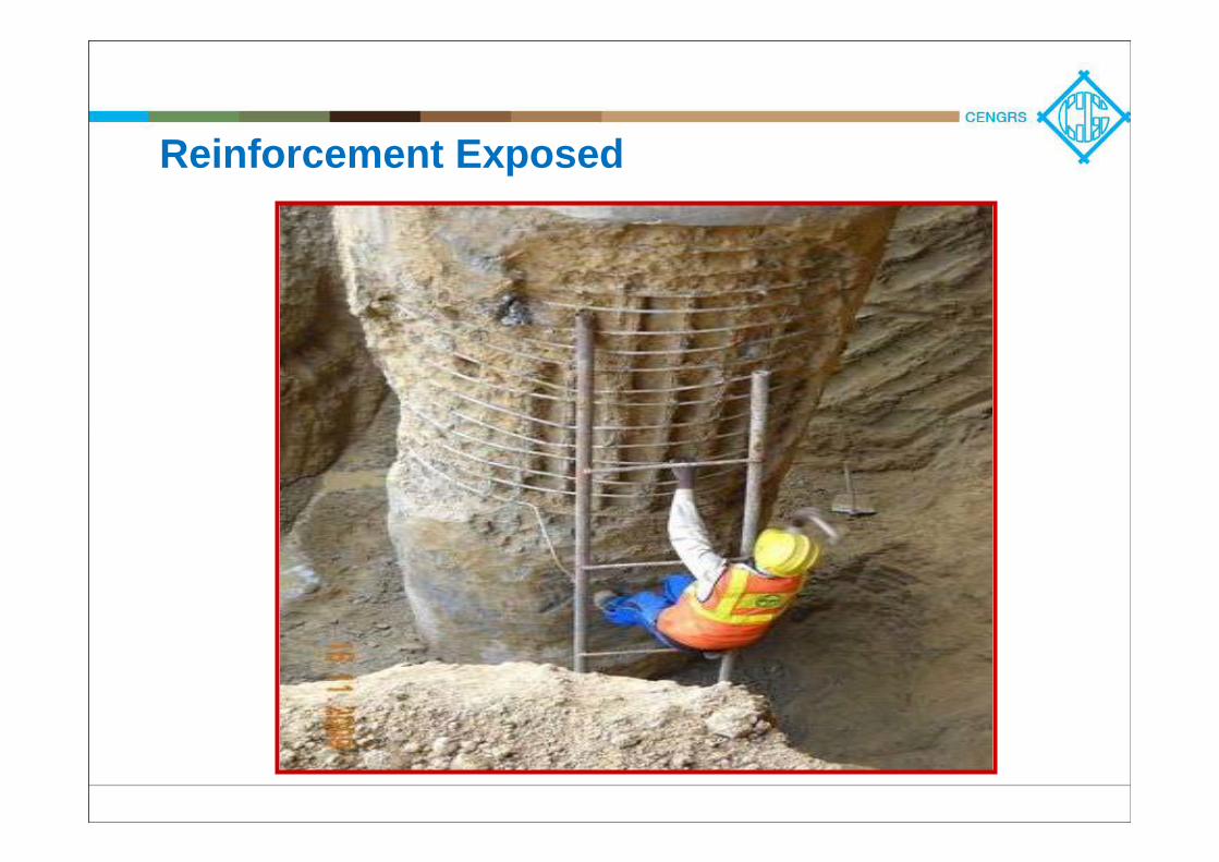
Repair Work in Progress
Safe Pile Capacities De-Rated
Additional piles installed below basement levelPiled-Raft analysis done to assess the overall settlement and safety of the foundation systemOf course it led to contractual issues:
Blame all involved – soil consultant, structural consultant, building contractor, piling agency – all were under scrutinyClient suffered!!Client suffered!! – Project delayed, resulted in direct & indirect losses

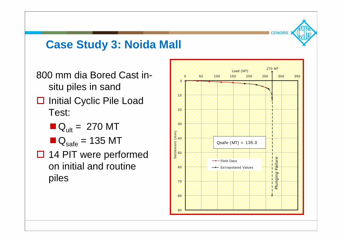
Case Study 3: Noida Mall
800 mm dia Bored Cast in-situ piles in sandInitial Cyclic Pile Load Test:
Qult = 270 MTQsafe = 135 MT
14 PIT were performed on initial and routine piles
0
10
20
30
40
50
60
70
80
90
0 50 100 150 200 250 300 350
Load (MT)
Sett
lem
ent
(mm
)
Field Data
Extrapolated Values
Qsafe (MT) = 135.0
Plungi
ng
Failu
re
270 MT
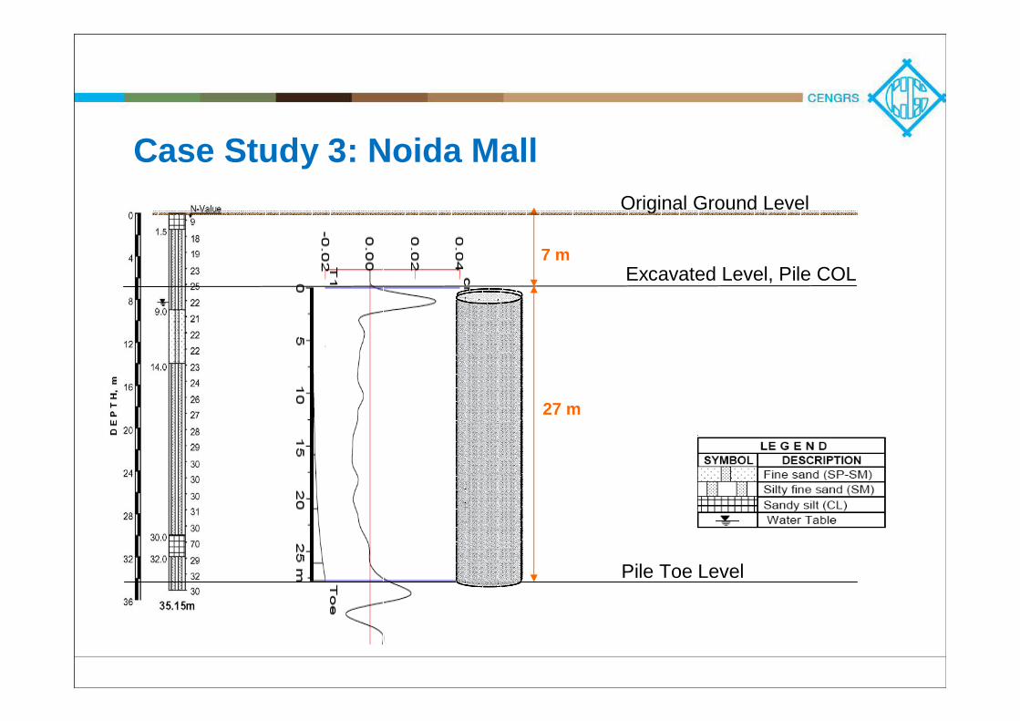
Case Study 3: Noida Mall
7 m
Original Ground Level
Excavated Level, Pile COL
Pile Toe Level
27 m
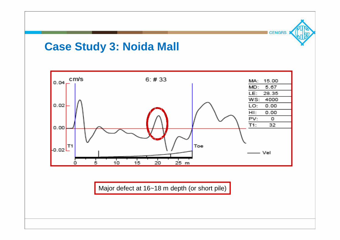
Case Study 3: Noida Mall
Major defect at 16~18 m depth (or short pile)
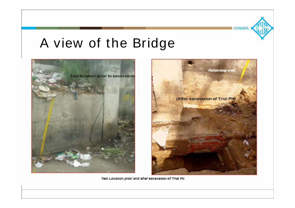
A view of the Bridge
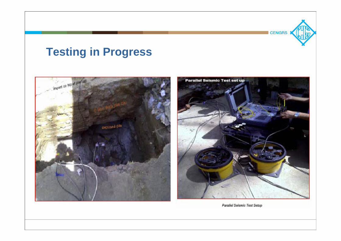
Testing in Progress
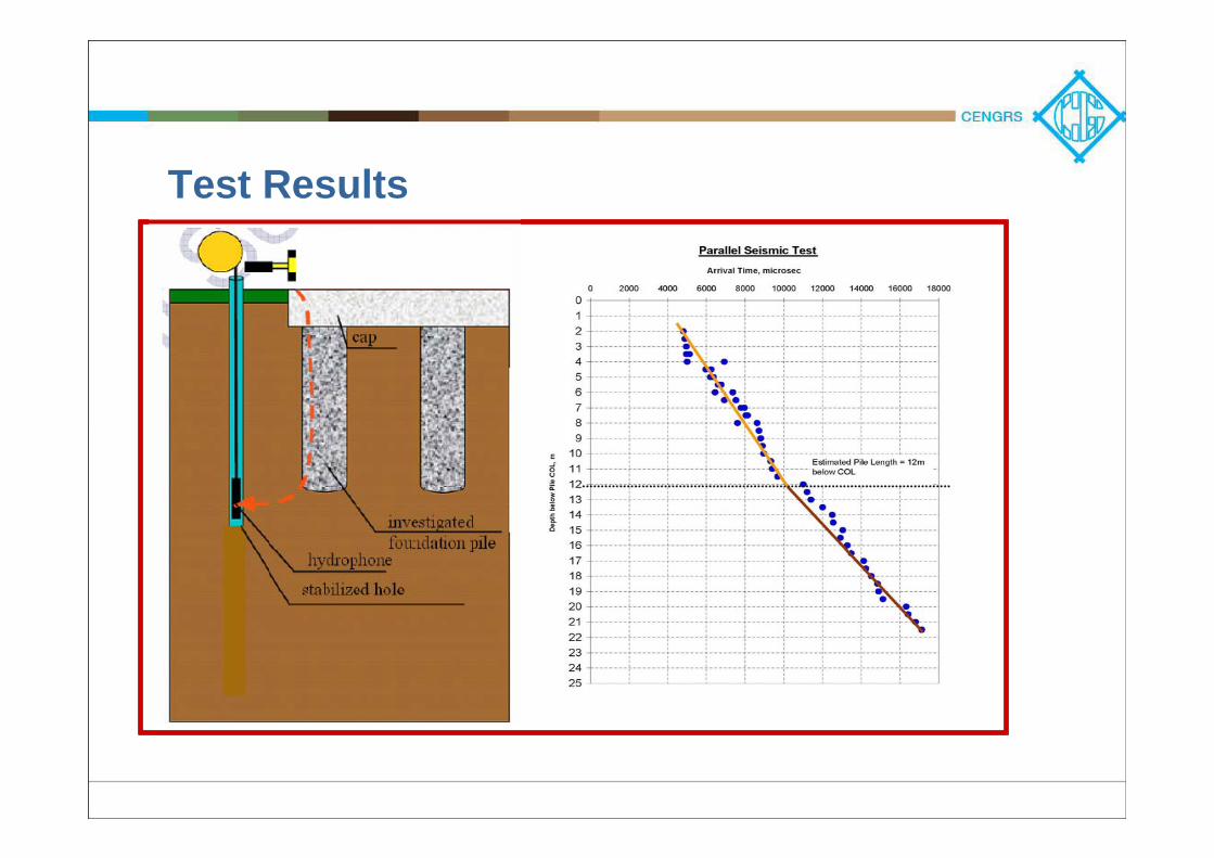
Test Results

““There is many a slip twixt the cup and the There is many a slip twixt the cup and the liplip””
A well-planned, comprehensive & robust QA program for the
foundations is essential to ensure adequate performance and
avert disaster
Keep the geotechnical engineer the and structural engineer
involved throughout the foundation construction process
More testing justifies lower F.S., leading to More testing justifies lower F.S., leading to significant significant cost savingscost savings

Just doing the tests is not enough! Just doing the tests is not enough!
Proper interpretation of the test results by an independent agencyCorrelate all information and test results -geotechnical data, pour card information, test results, etc.Improve the design as well as the construction methodology in parallel to get maximum benefitMany reliable test methods available, but Many reliable test methods available, but results are only as good as the testing results are only as good as the testing agency!!agency!!
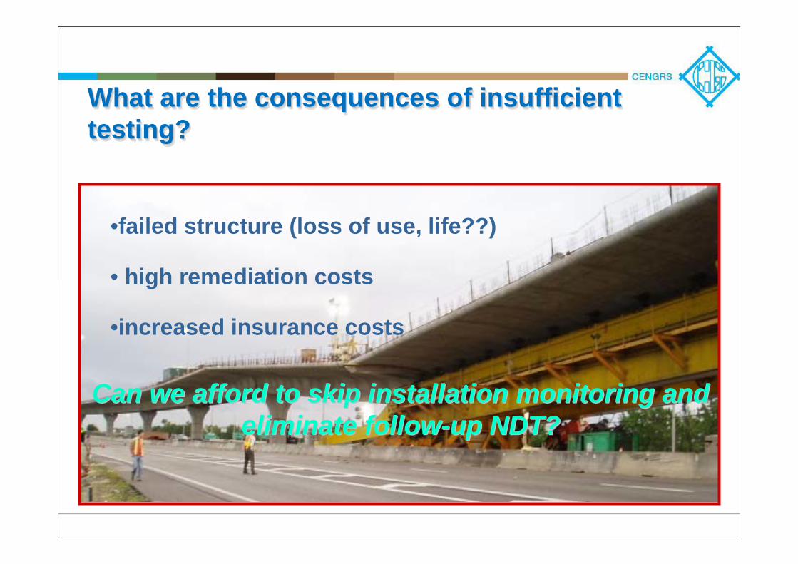
What are the consequences of insufficient testing?What are the consequences of insufficient What are the consequences of insufficient testing?testing?
•failed structure (loss of use, life??)
• high remediation costs
•increased insurance costs
Can we afford to skip installation monitoring and Can we afford to skip installation monitoring and eliminate followeliminate follow--up NDT?up NDT?

Let us strive to achieve quality in pile construction
THANK YOU…
Cengrs Geotechnica Pvt. Ltd
Top Related