σz −σx )d y, V - Springerextras.springer.com/2007/978-1-4020-6238-4/data/full_papers/141... ·...
8
Modern photoelasticity for residual stress measurement in glass Hillar Aben, Johan Anton, and Andrei Errapart GlasStress Ltd., 21 Akadeemia tee,12618 Tallinn, Estonia; [email protected] ABSTRACT This paper gives a review of the modern photoelastic technology for residual stress measurement in various glass articles, including glass articles of complicated shape. For residual stress measurement in axisymmetric glass articles, integrated photoelasticity is being used already by many glass companies and research laboratories. In case of nonaxisymmetric glass articles of complicated shape, photoelastic tomography is to be used. As for automotive and architectural glass panels used in buildings, surface stress can be measured with the mirage method. More complete stress analysis can be carried out with the scattered light method. The paper is illustrated by numerous examples. 1. Axisymmetric glass articles 1.1. Integrated Photoelasticity Photoelastic effect in glass was discovered by Estonian-German physicist Seebeck in 1813 [1]. Since then photoelasticity has been widely used for the estimation of the residual stress in glass. However, until the middle of the last century this estimation has been mostly qualitative, based on the observation of the interference colours. Since then many quantitative photoelastic techniques for glass stress analysis have been elaborated. A review of most of them one may find in the book [2]. One of the techniques that can be used for stress measurement in glass articles of complicated shape is integrated photoelasticity [3]. In integrated photoelasticity the test object is placed in an immersion tank and a beam of polarised light is passed through it (Fig. 1a). Measurements are carried out with a computer-controlled polariscope (Fig. 1b).Transformation of the polarisation of light in the specimen is measured on many light rays. Since the values and directions of the principal stresses vary on the light rays, optical phenomena in integrated photoelasticity are complicated and the relationships between the measurement data and parameters of the stress distribution are non-linear. However, it has been shown [4] that if birefringence is weak or rotation of the principal stress directions on the light rays is weak, a three-dimensional specimen can be investigated in a conventional transmission polariscope similarly to two- dimensional specimens. On every light ray it is possible to determine the parameter of the isoclinic φ and the optical retardation δ. The latter are related to the components of the stress tensor on the ray by simple integral relationships , d 2 2 sin , d ) ( 2 cos 2 1 y C V y C V zx x z ∫ ∫ = = - = = τ ϕ δ σ σ ϕ δ (1) where C is the photoelastic constant and σx, σz, and τzx are components of the stress tensor in the plane perpendicular to the light ray y. Formulas (1) and (2) express the integral Wertheim law. (a) (b) Figure 1. Experimental set-up in integrated photoelasticity (a) and automatic polariscope AP-06 C (b).
Transcript of σz −σx )d y, V - Springerextras.springer.com/2007/978-1-4020-6238-4/data/full_papers/141... ·...
Modern photoelasticity for residual stress measurement in glass
Hillar Aben, Johan Anton, and Andrei Errapart GlasStress Ltd., 21 Akadeemia tee,12618 Tallinn, Estonia; [email protected]
ABSTRACT
This paper gives a review of the modern photoelastic technology for residual stress measurement in various glass articles, including glass articles of complicated shape. For residual stress measurement in axisymmetric glass articles, integrated photoelasticity is being used already by many glass companies and research laboratories. In case of nonaxisymmetric glass articles of complicated shape, photoelastic tomography is to be used. As for automotive and architectural glass panels used in buildings, surface stress can be measured with the mirage method. More complete stress analysis can be carried out with the scattered light method. The paper is illustrated by numerous examples.
1. Axisymmetric glass articles
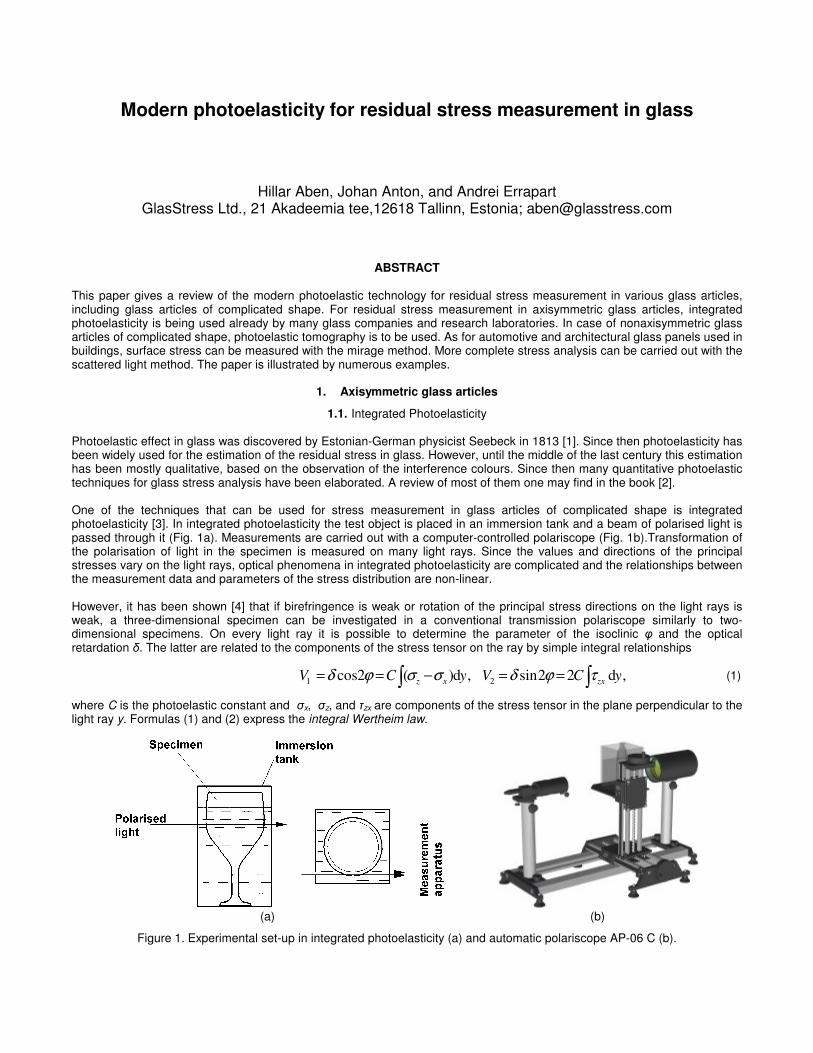
1.1. Integrated Photoelasticity Photoelastic effect in glass was discovered by Estonian-German physicist Seebeck in 1813 [1]. Since then photoelasticity has been widely used for the estimation of the residual stress in glass. However, until the middle of the last century this estimation has been mostly qualitative, based on the observation of the interference colours. Since then many quantitative photoelastic techniques for glass stress analysis have been elaborated. A review of most of them one may find in the book [2]. One of the techniques that can be used for stress measurement in glass articles of complicated shape is integrated photoelasticity [3]. In integrated photoelasticity the test object is placed in an immersion tank and a beam of polarised light is passed through it (Fig. 1a). Measurements are carried out with a computer-controlled polariscope (Fig. 1b).Transformation of the polarisation of light in the specimen is measured on many light rays. Since the values and directions of the principal stresses vary on the light rays, optical phenomena in integrated photoelasticity are complicated and the relationships between the measurement data and parameters of the stress distribution are non-linear. However, it has been shown [4] that if birefringence is weak or rotation of the principal stress directions on the light rays is weak, a three-dimensional specimen can be investigated in a conventional transmission polariscope similarly to two-dimensional specimens. On every light ray it is possible to determine the parameter of the isoclinic φ and the optical retardation δ. The latter are related to the components of the stress tensor on the ray by simple integral relationships
,d 22sin ,d)(2 cos 2 1
yCVyCV zxxz ∫∫ ==−== τϕδσσϕδ (1)
where C is the photoelastic constant and σx, σz, and τzx are components of the stress tensor in the plane perpendicular to the light ray y. Formulas (1) and (2) express the integral Wertheim law.
(a) (b)
Figure 1. Experimental set-up in integrated photoelasticity (a) and automatic polariscope AP-06 C (b).
It has been shown that if the parameter of the isoclinic φ and optical retardation δ have been measured on many light rays in two parallel sections, perpendicular to the axis z of the axisymmetric specimen, then radial distribution of the axial stress σz and shear stress τrz can be determined [2]. Using the equilibrium equation and the sum rule all the stress components can be determined [5,6].
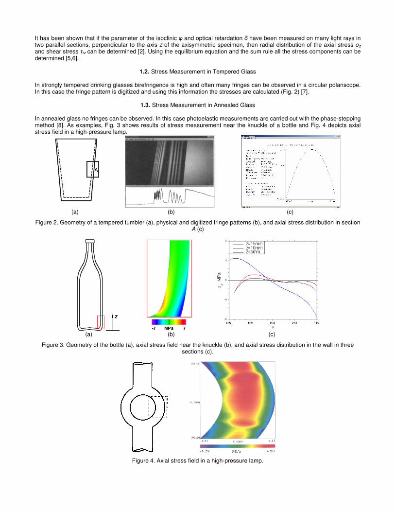
1.2. Stress Measurement in Tempered Glass In strongly tempered drinking glasses birefringence is high and often many fringes can be observed in a circular polariscope. In this case the fringe pattern is digitized and using this information the stresses are calculated (Fig. 2) [7].
1.3. Stress Measurement in Annealed Glass In annealed glass no fringes can be observed. In this case photoelastic measurements are carried out with the phase-stepping method [8]. As examples, Fig. 3 shows results of stress measurement near the knuckle of a bottle and Fig. 4 depicts axial stress field in a high-pressure lamp.
(a) (b) (c)
Figure 2. Geometry of a tempered tumbler (a), physical and digitized fringe patterns (b), and axial stress distribution in section A (c)
(a) (b) (c)
Figure 3. Geometry of the bottle (a), axial stress field near the knuckle (b), and axial stress distribution in the wall in three sections (c).
Figure 4. Axial stress field in a high-pressure lamp.
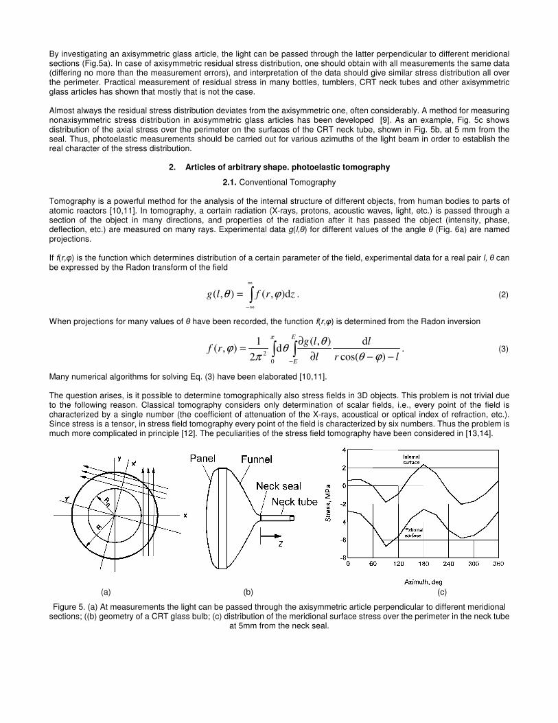
By investigating an axisymmetric glass article, the light can be passed through the latter perpendicular to different meridional sections (Fig.5a). In case of axisymmetric residual stress distribution, one should obtain with all measurements the same data (differing no more than the measurement errors), and interpretation of the data should give similar stress distribution all over the perimeter. Practical measurement of residual stress in many bottles, tumblers, CRT neck tubes and other axisymmetric glass articles has shown that mostly that is not the case. Almost always the residual stress distribution deviates from the axisymmetric one, often considerably. A method for measuring nonaxisymmetric stress distribution in axisymmetric glass articles has been developed [9]. As an example, Fig. 5c shows distribution of the axial stress over the perimeter on the surfaces of the CRT neck tube, shown in Fig. 5b, at 5 mm from the seal. Thus, photoelastic measurements should be carried out for various azimuths of the light beam in order to establish the real character of the stress distribution.
2. Articles of arbitrary shape. photoelastic tomography
2.1. Conventional Tomography Tomography is a powerful method for the analysis of the internal structure of different objects, from human bodies to parts of atomic reactors [10,11]. In tomography, a certain radiation (X-rays, protons, acoustic waves, light, etc.) is passed through a section of the object in many directions, and properties of the radiation after it has passed the object (intensity, phase, deflection, etc.) are measured on many rays. Experimental data g(l,θ) for different values of the angle θ (Fig. 6a) are named projections. If f(r,φ) is the function which determines distribution of a certain parameter of the field, experimental data for a real pair l, θ can be expressed by the Radon transform of the field
. d),(),( zrflg ϕθ ∫∞
∞−
= (2)
When projections for many values of θ have been recorded, the function f(r,φ) is determined from the Radon inversion
. )cos(
d),(d
2
1),(
0
2 lr
l
l
lgrf
E
E−−∂
∂= ∫ ∫
−ϕθ
θθ
πϕ
π
(3)
Many numerical algorithms for solving Eq. (3) have been elaborated [10,11]. The question arises, is it possible to determine tomographically also stress fields in 3D objects. This problem is not trivial due to the following reason. Classical tomography considers only determination of scalar fields, i.e., every point of the field is characterized by a single number (the coefficient of attenuation of the X-rays, acoustical or optical index of refraction, etc.). Since stress is a tensor, in stress field tomography every point of the field is characterized by six numbers. Thus the problem is much more complicated in principle [12]. The peculiarities of the stress field tomography have been considered in [13,14].
(a) (b) (c)
Figure 5. (a) At measurements the light can be passed through the axisymmetric article perpendicular to different meridional sections; ((b) geometry of a CRT glass bulb; (c) distribution of the meridional surface stress over the perimeter in the neck tube
at 5mm from the neck seal.
(a) (b)
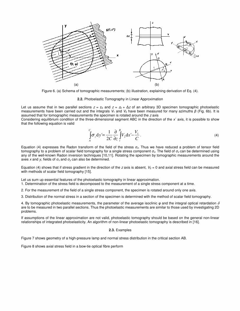
Figure 6. (a) Schema of tomographic measurements; (b) illustration, explaining derivation of Eq. (4).
2.2. Photoelastic Tomography in Linear Approximation Let us assume that in two parallel sections z = z0 and z = z0 + ∆z of an arbitrary 3D specimen tomographic photoelastic measurements have been carried out and the integrals V1 and V2 have been measured for many azimuths β (Fig. 6b). It is assumed that for tomographic measurements the specimen is rotated around the z axis Considering equilibrium condition of the three-dimensional segment ABC in the direction of the x´ axis, it is possible to show that the following equation is valid
∫∫ −∂
∂=
B
l
C
A
zC
VxV
zCy 1
2 ´d2
1´dσ . (4)
Equation (4) expresses the Radon transform of the field of the stress σz. Thus we have reduced a problem of tensor field tomography to a problem of scalar field tomography for a single stress component σz. The field of σz can be determined using any of the well-known Radon inversion techniques [10,11]. Rotating the specimen by tomographic measurements around the axes x and y, fields of σx and σy can also be determined. Equation (4) shows that if stress gradient in the direction of the z axis is absent, V2 = 0 and axial stress field can be measured with methods of scalar field tomography [15]. Let us sum up essential features of the photoelastic tomography in linear approximation. 1. Determination of the stress field is decomposed to the measurement of a single stress component at a time.
2. For the measurement of the field of a single stress component, the specimen is rotated around only one axis.
3. Distribution of the normal stress in a section of the specimen is determined with the method of scalar field tomography.
4. By tomographic photoelastic measurements, the parameter of the average isoclinic φ and the integral optical retardation δ are to be measured in two parallel sections. Thus the photoelastic measurements are similar to those used by investigating 2D problems.
If assumptions of the linear approximation are not valid, photoelastic tomography should be based on the general non-linear relationships of integrated photoelasticity. An algorithm of non-linear photoelastic tomography is described in [16].
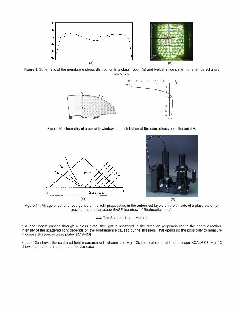
2.3. Examples Figure 7 shows geometry of a high-pressure lamp and normal stress distribution in the critical section AB. Figure 8 shows axial stress field in a bow-tie optical fibre perform
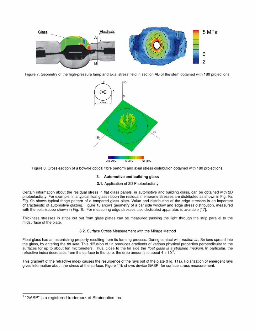
Figure 7. Geometry of the high-pressure lamp and axial stress field in section AB of the stem obtained with 180 projections.
Figure 8. Cross-section of a bow-tie optical fibre perform and axial stress distribution obtained with 180 projections.
3. Automotive and building glass
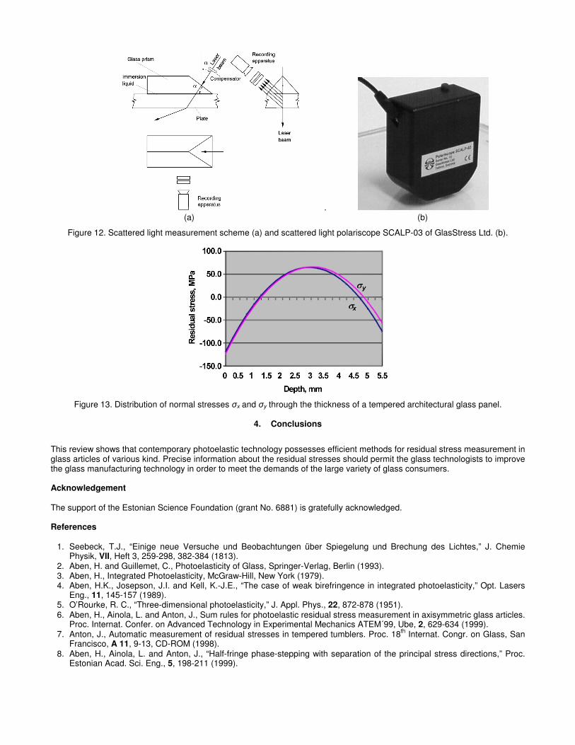
3.1. Application of 2D Photoelasticity Certain information about the residual stress in flat glass panels, in automotive and building glass, can be obtained with 2D photoelasticity. For example, in a typical float glass ribbon the residual membrane stresses are distributed as shown in Fig. 9a. Fig. 9b shows typical fringe pattern of a tempered glass plate. Value and distribution of the edge stresses is an important characteristic of automotive glazing. Figure 10 shows geometry of a car side window and edge stress distribution, measured with the polariscope shown in Fig. 1b. For measuring edge stresses also dedicated apparatus is available [17]. Thickness stresses in strips cut out from glass plates can be measured passing the light through the strip parallel to the midsurface of the plate.
3.2. Surface Stress Measurement with the Mirage Method Float glass has an astonishing property resulting from its forming process. During contact with molten tin, Sn ions spread into the glass, by entering the tin side. This diffusion of tin produces gradients of various physical properties perpendicular to the surfaces for up to about ten micrometers. Thus, close to the tin side the float glass is a stratified medium. In particular, the refractive index decreases from the surface to the core: the drop amounts to about 4 × 10
-3.
This gradient of the refractive index causes the resurgence of the rays out of the plate (Fig. 11a). Polarization of emergent rays gives information about the stress at the surface. Figure 11b shows device GASP
1 for surface stress measurement.
1 “GASP” is a registered trademark of Strainoptics Inc.
(a) (b)
Figure 9. Schematic of the membrane stress distribution in a glass ribbon (a) and typical fringe pattern of a tempered glass plate (b).
Figure 10. Geometry of a car side window and distribution of the edge stress near the point A.
(a) (b)
Figure 11. Mirage effect and resurgence of the light propagating in the outermost layers on the tin side of a glass plate; (b) grazing angle polariscope GASP (courtesy of Strainoptics, Inc.).
3.3. The Scattered Light Method
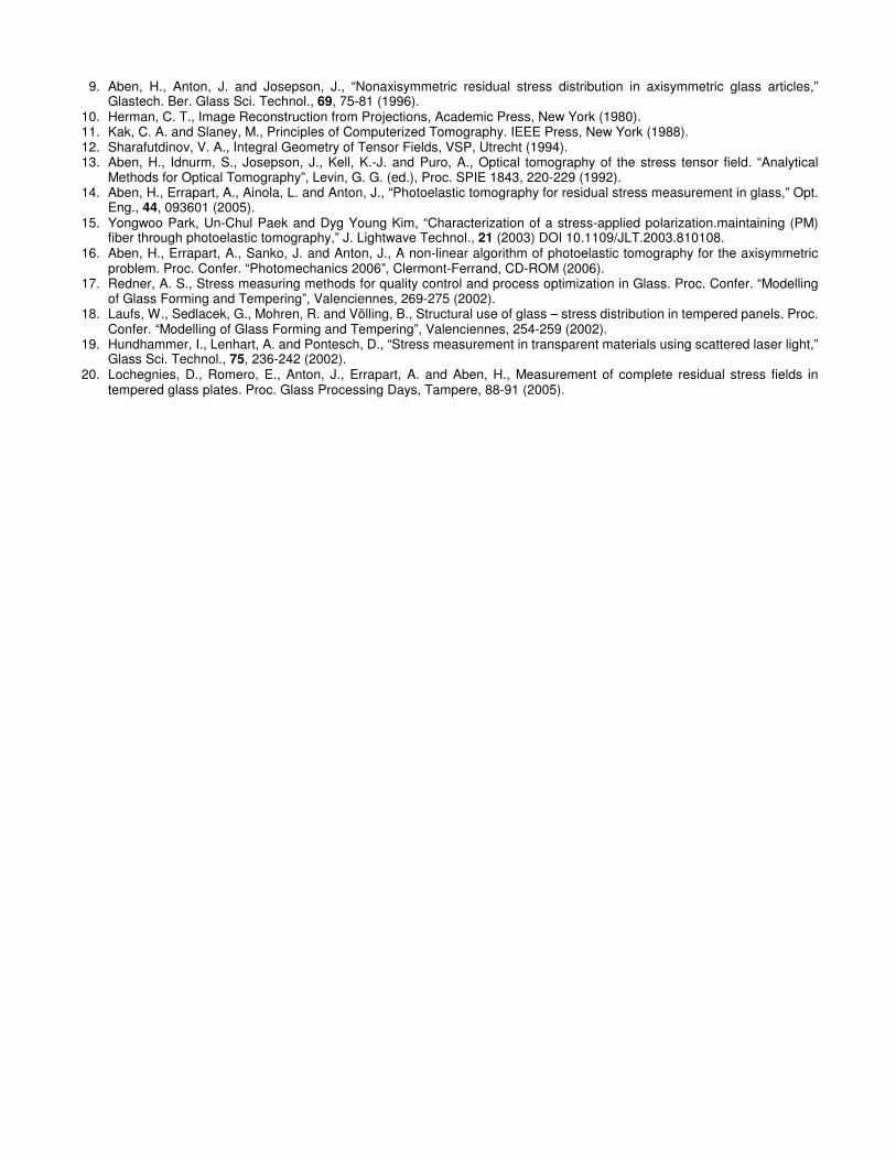
If a laser beam passes through a glass plate, the light is scattered in the direction perpendicular to the beam direction. Intensity of the scattered light depends on the birefringence caused by the stresses. That opens up the possibility to measure thickness stresses in glass plates [2,18–20]. Figure 12a shows the scattered light measurement scheme and Fig. 12b the scattered light polariscope SCALP-03. Fig. 13 shows measurement data in a particular case
. (a) (b)
Figure 12. Scattered light measurement scheme (a) and scattered light polariscope SCALP-03 of GlasStress Ltd. (b).
Figure 13. Distribution of normal stresses σx and σy through the thickness of a tempered architectural glass panel.
4. Conclusions
This review shows that contemporary photoelastic technology possesses efficient methods for residual stress measurement in glass articles of various kind. Precise information about the residual stresses should permit the glass technologists to improve the glass manufacturing technology in order to meet the demands of the large variety of glass consumers. Acknowledgement The support of the Estonian Science Foundation (grant No. 6881) is gratefully acknowledged. References
1. Seebeck, T.J., “Einige neue Versuche und Beobachtungen über Spiegelung und Brechung des Lichtes,” J. Chemie Physik, VII, Heft 3, 259-298, 382-384 (1813).
2. Aben, H. and Guillemet, C., Photoelasticity of Glass, Springer-Verlag, Berlin (1993). 3. Aben, H., Integrated Photoelasticity, McGraw-Hill, New York (1979). 4. Aben, H.K., Josepson, J.I. and Kell, K.-J.E., “The case of weak birefringence in integrated photoelasticity,” Opt. Lasers
Eng., 11, 145-157 (1989). 5. O’Rourke, R. C., “Three-dimensional photoelasticity,” J. Appl. Phys., 22, 872-878 (1951). 6. Aben, H., Ainola, L. and Anton, J., Sum rules for photoelastic residual stress measurement in axisymmetric glass articles.
Proc. Internat. Confer. on Advanced Technology in Experimental Mechanics ATEM´99, Ube, 2, 629-634 (1999). 7. Anton, J., Automatic measurement of residual stresses in tempered tumblers. Proc. 18
th Internat. Congr. on Glass, San
Francisco, A 11, 9-13, CD-ROM (1998). 8. Aben, H., Ainola, L. and Anton, J., “Half-fringe phase-stepping with separation of the principal stress directions,” Proc.
Estonian Acad. Sci. Eng., 5, 198-211 (1999).
9. Aben, H., Anton, J. and Josepson, J., “Nonaxisymmetric residual stress distribution in axisymmetric glass articles,” Glastech. Ber. Glass Sci. Technol., 69, 75-81 (1996).
10. Herman, C. T., Image Reconstruction from Projections, Academic Press, New York (1980). 11. Kak, C. A. and Slaney, M., Principles of Computerized Tomography. IEEE Press, New York (1988). 12. Sharafutdinov, V. A., Integral Geometry of Tensor Fields, VSP, Utrecht (1994). 13. Aben, H., Idnurm, S., Josepson, J., Kell, K.-J. and Puro, A., Optical tomography of the stress tensor field. “Analytical
Methods for Optical Tomography”, Levin, G. G. (ed.), Proc. SPIE 1843, 220-229 (1992). 14. Aben, H., Errapart, A., Ainola, L. and Anton, J., “Photoelastic tomography for residual stress measurement in glass,” Opt.
Eng., 44, 093601 (2005). 15. Yongwoo Park, Un-Chul Paek and Dyg Young Kim, “Characterization of a stress-applied polarization.maintaining (PM)
fiber through photoelastic tomography,” J. Lightwave Technol., 21 (2003) DOI 10.1109/JLT.2003.810108. 16. Aben, H., Errapart, A., Sanko, J. and Anton, J., A non-linear algorithm of photoelastic tomography for the axisymmetric
problem. Proc. Confer. “Photomechanics 2006”, Clermont-Ferrand, CD-ROM (2006). 17. Redner, A. S., Stress measuring methods for quality control and process optimization in Glass. Proc. Confer. “Modelling
of Glass Forming and Tempering”, Valenciennes, 269-275 (2002). 18. Laufs, W., Sedlacek, G., Mohren, R. and Völling, B., Structural use of glass – stress distribution in tempered panels. Proc.
Confer. “Modelling of Glass Forming and Tempering”, Valenciennes, 254-259 (2002). 19. Hundhammer, I., Lenhart, A. and Pontesch, D., “Stress measurement in transparent materials using scattered laser light,”
Glass Sci. Technol., 75, 236-242 (2002). 20. Lochegnies, D., Romero, E., Anton, J., Errapart, A. and Aben, H., Measurement of complete residual stress fields in
tempered glass plates. Proc. Glass Processing Days, Tampere, 88-91 (2005).