Ultrashort Pulses - InTech - Open Science Open Minds | InTechOpen
26
4 Ultrashort Pulses Mikhail N. Polyanskiy and Marcus Babzien Brookhaven National Laboratory USA 1. Introduction 1.1 Niche for ultrashort-pulse CO 2 lasers Ultrashort pulses usually are defined as those lasting less than a nanosecond. Low-energetic ultrashort pulses can be used, for instance, as a probe for studying the dynamics of ultrafast processes. Amplifying these pulses can deliver extremely high peak power, allowing applications such as laser particle acceleration, or γ-ray generation via Compton scattering on relativistic electrons. Existing laser systems can provide pulses as brief as hundreds of attoseconds (10 -18 s) and as powerful as tens of petawatts (10 15 W); more advanced ones are being constructed or are planned (Corkum & Krausz, 2007, Korzhimanov et al., 2011). Virtually all modern ultrashort-pulse lasers are based on solid-state technology and usually operate at ~1 µm wavelength. Nevertheless, these applications relying not only on the ultrashort duration or the extreme power of the laser pulse, but also on its wavelength, leave a niche for laser systems utilizing different types of active medium. The 10-micron wavelength of the CO 2 laser particularly is beneficial for some usages. To demonstrate the potential of ultrashort, mid-IR pulses, we consider their employment for laser ion acceleration, presently one of the main drivers for developing ultrashort-pulse CO 2 lasers (Palmer et al., 2011, Norreys, 2011). The motivation underlying the search for alternatives to conventional accelerators, wherein a system of electrodes and magnets creates the accelerating field, is the need to reduce the size and the cost of these devices. Acceleration in the electromagnetic field of a laser beam is a promising alternative for traditional acceleration schemes. In laser ion acceleration, an intense laser pulse focused on a target first ionizes it and then accelerates the charged particles from the resulting plasma. Usually this target is a metal foil, and a ~1 µm, multi-TW peak power, solid-state laser provides the ionizing/accelerating field. A very efficient acceleration regime called Radiation Pressure Acceleration (RPA) featuring a narrow energy-spectrum of the accelerated ions is reached when laser pulse interacts with plasma having a near-critical density (Esirkepov et al., 2004). The following formula defines critical plasma density, N c (the density at which plasma becomes opaque): 2 -3 21 [cm ] 1.115 10 [Ǎm] c n N λ ≈ × , (1) www.intechopen.com
Transcript of Ultrashort Pulses - InTech - Open Science Open Minds | InTechOpen
4
Ultrashort Pulses
Mikhail N. Polyanskiy and Marcus Babzien Brookhaven National Laboratory
USA
1. Introduction
1.1 Niche for ultrashort-pulse CO2 lasers
Ultrashort pulses usually are defined as those lasting less than a nanosecond. Low-energetic
ultrashort pulses can be used, for instance, as a probe for studying the dynamics of ultrafast
processes. Amplifying these pulses can deliver extremely high peak power, allowing
applications such as laser particle acceleration, or γ-ray generation via Compton
scattering on relativistic electrons. Existing laser systems can provide pulses as brief as
hundreds of attoseconds (10-18 s) and as powerful as tens of petawatts (1015 W); more
advanced ones are being constructed or are planned (Corkum & Krausz, 2007,
Korzhimanov et al., 2011).
Virtually all modern ultrashort-pulse lasers are based on solid-state technology and usually
operate at ~1 µm wavelength. Nevertheless, these applications relying not only on the
ultrashort duration or the extreme power of the laser pulse, but also on its wavelength, leave
a niche for laser systems utilizing different types of active medium. The 10-micron
wavelength of the CO2 laser particularly is beneficial for some usages.
To demonstrate the potential of ultrashort, mid-IR pulses, we consider their employment for laser ion acceleration, presently one of the main drivers for developing ultrashort-pulse CO2 lasers (Palmer et al., 2011, Norreys, 2011). The motivation underlying the search for alternatives to conventional accelerators, wherein a system of electrodes and magnets creates the accelerating field, is the need to reduce the size and the cost of these devices. Acceleration in the electromagnetic field of a laser beam is a promising alternative for traditional acceleration schemes. In laser ion acceleration, an intense laser pulse focused on a target first ionizes it and then accelerates the charged particles from the resulting plasma. Usually this target is a metal foil, and a ~1 µm, multi-TW peak power, solid-state laser provides the ionizing/accelerating field. A very efficient acceleration regime called Radiation Pressure Acceleration (RPA) featuring a narrow energy-spectrum of the accelerated ions is reached when laser pulse interacts with plasma having a near-critical density (Esirkepov et al., 2004). The following formula defines critical plasma density, Nc (the density at which plasma becomes opaque):
2
-3 21[cm ] 1.115 10[┤m]
c
nN
λ
≈ × , (1)
www.intechopen.com
CO2 Laser – Optimisation and Application
140
where n is the refractive index, and λ the laser wavelength. According to the Eq. (1), Nc is ~1021 cm-3 for the 1-µm lasers, and ~1019 cm-3 for the 10-µm lasers. These densities are much lower than that of solid materials. The critical density at 10 µm is comparable with the density of gases (~2.7×1019 cm-3 at 1 bar); thus, it readily is achievable for the CO2 laser’s wavelength when the gas jet is used as a target. On the other hand, realizing the critical-density jet for 1-µm solid-state lasers is challenging. Another advantage of the longer wavelength for ion acceleration in the RPA regime is the ┣2 scaling of the ponderomotive force, implying that a 100x lower intensity of the CO2 laser field will suffice for reaching a given ion energy compared with a solid-state laser.
Yet another simple consideration favors CO2 lasers for certain applications: A 10-µm laser pulse carries 10x more photons than a 1-µm pulse of the same energy. Photon density is important for applications such as γ-ray generation by Compton scattering on relativistic electrons (Yakimenko & Pogorelsky, 2006).
1.2 Challenge of high peak power
The minimum achievable duration of the pulse is defined by the bandwidth of the gain spectrum. In the simplest case of the absence of chirping (frequency variation with time), the spectrum of a pulse is the Fourier transform of its temporal profile. The pulse then is called transform-limited, and its duration, τp, is inversely proportional to its spectral width, Δνp. The following expression is valid for a transform-limited Gaussian pulse (Paschotta, 2008):
0.44
p
p
τν
≈Δ
, (2)
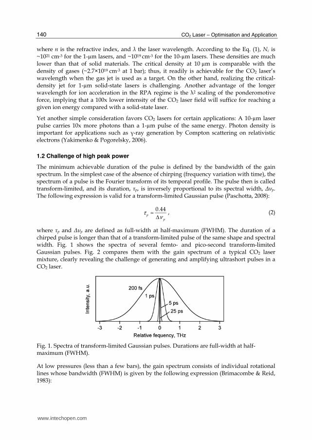
where τp and Δνp are defined as full-width at half-maximum (FWHM). The duration of a chirped pulse is longer than that of a transform-limited pulse of the same shape and spectral width. Fig. 1 shows the spectra of several femto- and pico-second transform-limited Gaussian pulses. Fig. 2 compares them with the gain spectrum of a typical CO2 laser mixture, clearly revealing the challenge of generating and amplifying ultrashort pulses in a CO2 laser.
Fig. 1. Spectra of transform-limited Gaussian pulses. Durations are full-width at half-maximum (FWHM).
At low pressures (less than a few bars), the gain spectrum consists of individual rotational lines whose bandwidth (FWHM) is given by the following expression (Brimacombe & Reid, 1983):
www.intechopen.com
Ultrashort Pulses
141
[ ] [ ] ( )2 2Δ GHz bar 5.79 4.25 3.55pressure CO N Heν P≈ ⋅ Ψ + Ψ + Ψ , (3)
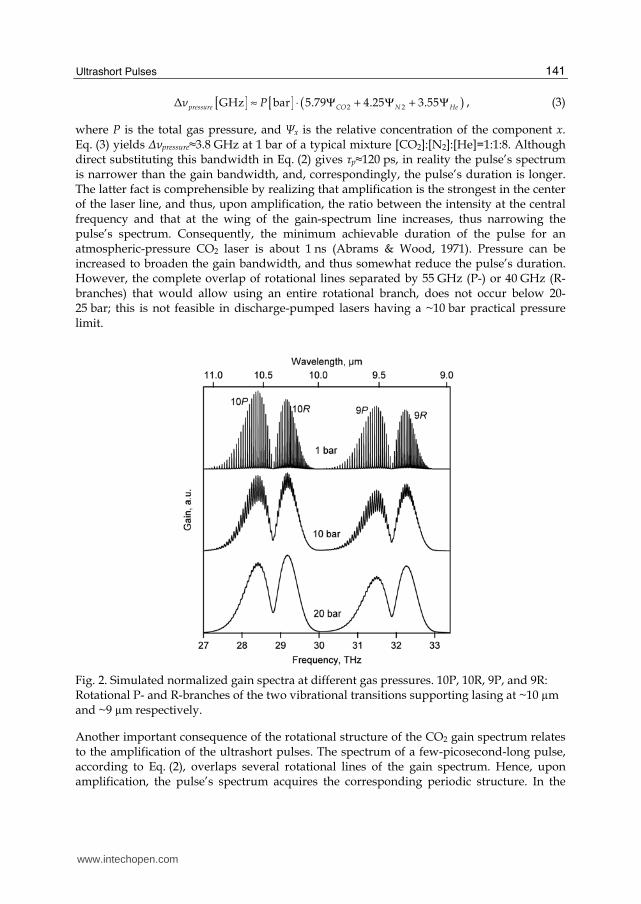
where P is the total gas pressure, and ┐x is the relative concentration of the component x. Eq. (3) yields Δνpressure≈3.8 GHz at 1 bar of a typical mixture [CO2]:[N2]:[He]=1:1:8. Although direct substituting this bandwidth in Eq. (2) gives τp≈120 ps, in reality the pulse’s spectrum is narrower than the gain bandwidth, and, correspondingly, the pulse’s duration is longer. The latter fact is comprehensible by realizing that amplification is the strongest in the center of the laser line, and thus, upon amplification, the ratio between the intensity at the central frequency and that at the wing of the gain-spectrum line increases, thus narrowing the pulse’s spectrum. Consequently, the minimum achievable duration of the pulse for an atmospheric-pressure CO2 laser is about 1 ns (Abrams & Wood, 1971). Pressure can be increased to broaden the gain bandwidth, and thus somewhat reduce the pulse’s duration. However, the complete overlap of rotational lines separated by 55 GHz (P-) or 40 GHz (R-branches) that would allow using an entire rotational branch, does not occur below 20-25 bar; this is not feasible in discharge-pumped lasers having a ~10 bar practical pressure limit.
Fig. 2. Simulated normalized gain spectra at different gas pressures. 10P, 10R, 9P, and 9R: Rotational P- and R-branches of the two vibrational transitions supporting lasing at ~10 µm and ~9 µm respectively.
Another important consequence of the rotational structure of the CO2 gain spectrum relates to the amplification of the ultrashort pulses. The spectrum of a few-picosecond-long pulse, according to Eq. (2), overlaps several rotational lines of the gain spectrum. Hence, upon amplification, the pulse’s spectrum acquires the corresponding periodic structure. In the
www.intechopen.com

CO2 Laser – Optimisation and Application
142
time-domain (inverse Fourier-transform of the spectrum), this is equivalent to a pulse train with pulse-to-pulse distance equal to the inverse separation of the spectral lines (18 ps in the P-, and 25 ps in the R-branches). Fig. 3 demonstrates this effect for a 5-ps pulse amplified in a 10-bar active medium.
Fig. 3. Simulated dynamics of a 5-ps (FWHM) pulse spectrum (a), and its temporal structure normalized by the total energy in the train (b) amplified in a 10-bar CO2 amplifier. Dashed line: normalized gain spectrum.
We discuss below different approaches to overcome these difficulties.
2. Generating the seed pulse
In all modern schemes for producing ultrahigh-power laser pulses there are at least two major stages: (1) Generation of a low-power, ultrashort seed pulse, and, (2) amplification of the pulse. In this section, we consider different methods of creating ultrashort 10-µm pulses. Section 3, following, discusses the amplification stage.
2.1 Mode-locking
Mode-locking is the primary technique of generating ultrashort pulses in solid-state systems. In this approach, cavity modes present in the spectrum of the laser field are synchronized (locked) by modulating the cavity’s Q-factor at a frequency that is a multiple of the inverse of the resonator’s round-trip time, either actively (e.g., with an intra-cavity acousto-optical modulator), or passively (e.g., with a saturable absorber). Without synchronization, each mode is independent and defines its own pulse; thus, the pulse’s duration is only limited by the relatively narrow bandwidth of an individual mode. However, after mode-locking, the time structure of the laser field is defined by the entire spectrum comprising all active modes. For the periodic spectrum of longitudinal modes, this structure is a periodic train of pulses; the pulse’s repetition rate is equal to the lock-in
www.intechopen.com
Ultrashort Pulses
143
frequency (i.e., a multiple of the inter-mode distance), and individual pulse’s duration is inversely proportional to the total extent of the spectrum.
The minimum pulse duration achievable via mode-locking is related to the bandwidth, Δν, (FWHM) of the gain spectrum according the following expression (Siegman & Kuizenga, 1969):
( )1/4
1/20.45p
gf
Mτ ν
− ≈ ⋅ ⋅ Δ , (4)
where g≡2αL is the saturated round-trip excess gain (α – excess gain per unit length, L – resonator length), M is the modulation, and f=c/2L is its frequency. For a typical transversely excited atmospheric pressure (TEA) CO2 laser (g=1; M=1; f=150 MHz; Δν=3.8 GHz) the duration is τp≈600 ps. Wood et al. describe their technical realization of the mode-locked TEA CO2 laser (Wood et al., 1970, Abrams & Wood, 1971). A 10-bar mode-locked system was reported by Houtman and Meyer (Houtman & Meyer, 1987). Application of mode-locking is limited in 10-micron systems by relatively long (hundreds of picoseconds) pulse duration achievable via this technique.
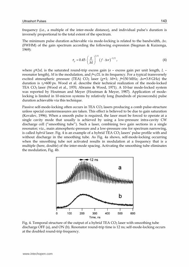
Passive self-mode-locking often occurs in TEA CO2 lasers producing a comb pulse-structure unless special countermeasures are taken. This effect is believed to be due to gain saturation (Kovalev, 1996). When a smooth pulse is required, the laser must be forced to operate at a single cavity mode that usually is achieved by using a low-pressure intra-cavity CW discharge cell (“smoothing tube”). Such a laser, combining two gain sections in a single resonator; viz., main atmospheric-pressure and a low-pressure one for spectrum narrowing, is called hybrid laser. Fig. 4 is an example of a hybrid TEA CO2 lasers’ pulse profile with and without discharge in the smoothing tube. As Fig. 4a shows, self-mode-locking occurring when the smoothing tube not activated results in modulation at a frequency that is a multiple (here, double) of the inter-mode spacing. Activating the smoothing tube eliminates the modulation, Fig. 4b.
Fig. 4. Temporal structure of the output of a hybrid TEA CO2 laser with smoothing tube discharge OFF (a), and ON (b). Resonator round-trip time is 12 ns; self-mode-locking occurs at the doubled round-trip frequency.
www.intechopen.com
CO2 Laser – Optimisation and Application
144
2.2 Plasma shutter and optical free-induction decay
Highly intense laser pulses focused in gas media can initiate avalanche ionization (laser breakdown). If gas density is high enough, overcritical plasma forms, blocking the trailing part of the laser pulse, partially absorbing and partially reflecting it. This effect itself, usually termed plasma shutter, can be used to cut the tail of the pulse thus reducing its overall duration. However, it is not sufficient for producing an ultrashort pulse because the front part of the initial pulse passes the plasma shutter unchanged. The possibility of generating a pulse as short as a few optical cycles lies in the fact that the fast switching-out of the laser field by plasma entails a very rapid variation in the field spectra. Essentially, we can approximate the spectrum of the transmitted pulse by the Fourier-transform of a step function. Frequencies different from those present in the original pulse briefly appear in the spectrum. If we now filter-out the frequency of the initial pulse from the resulting spectrum, we end up with a very short pulse (Yablonovich, 1973, 1974a, 1974b). Free-induction decay technique is relatively simple to realize and can allow achieving ~20 ps pulse duration at the expense of large losses and strong alteration of the spectrum.
2.3 Pulse-slicing techniques
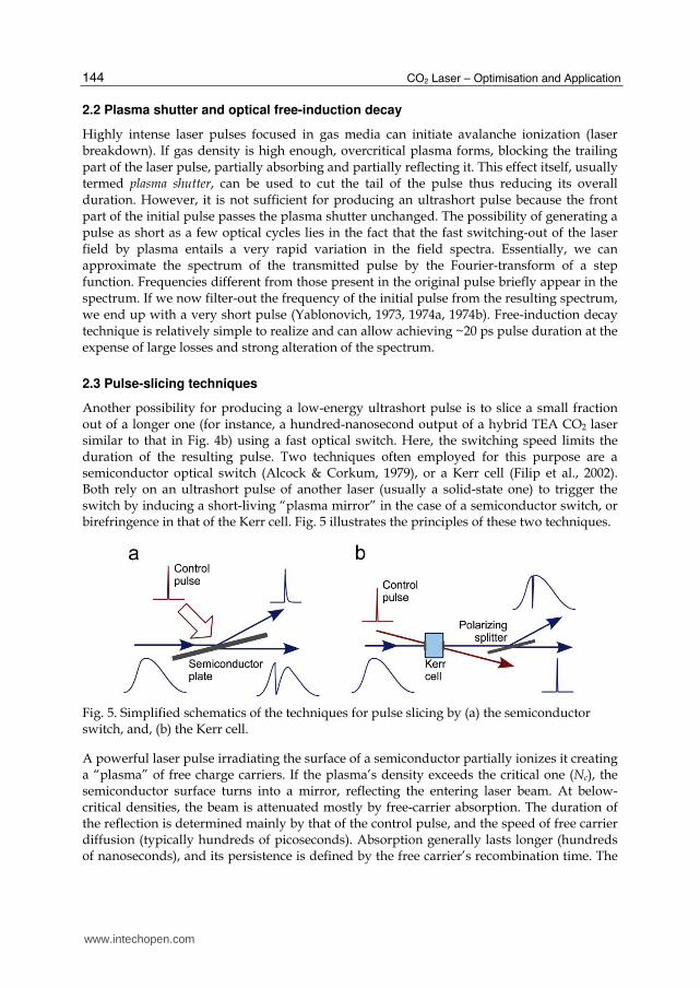
Another possibility for producing a low-energy ultrashort pulse is to slice a small fraction out of a longer one (for instance, a hundred-nanosecond output of a hybrid TEA CO2 laser similar to that in Fig. 4b) using a fast optical switch. Here, the switching speed limits the duration of the resulting pulse. Two techniques often employed for this purpose are a semiconductor optical switch (Alcock & Corkum, 1979), or a Kerr cell (Filip et al., 2002). Both rely on an ultrashort pulse of another laser (usually a solid-state one) to trigger the switch by inducing a short-living “plasma mirror” in the case of a semiconductor switch, or birefringence in that of the Kerr cell. Fig. 5 illustrates the principles of these two techniques.
Fig. 5. Simplified schematics of the techniques for pulse slicing by (a) the semiconductor switch, and, (b) the Kerr cell.
A powerful laser pulse irradiating the surface of a semiconductor partially ionizes it creating a “plasma” of free charge carriers. If the plasma’s density exceeds the critical one (Nc), the semiconductor surface turns into a mirror, reflecting the entering laser beam. At below-critical densities, the beam is attenuated mostly by free-carrier absorption. The duration of the reflection is determined mainly by that of the control pulse, and the speed of free carrier diffusion (typically hundreds of picoseconds). Absorption generally lasts longer (hundreds of nanoseconds), and its persistence is defined by the free carrier’s recombination time. The
www.intechopen.com
Ultrashort Pulses
145
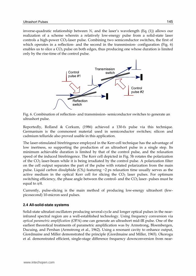
inverse-quadratic relationship between Nc and the laser’s wavelength (Eq. (1)) allows our realization of a scheme wherein a relatively low-energy pulse from a solid-state laser controls a high-power CO2-laser pulse. Combining two semiconductor switches, the first of which operates in a reflection- and the second in the transmission- configuration (Fig. 6) enables us to slice a CO2 pulse on both edges, thus producing one whose duration is limited only by the rise-time of the control pulse.
Fig. 6. Combination of reflection- and transmission- semiconductor switches to generate an ultrashort pulse.
Reportedly, Rolland & Corkum, (1986) achieved a 130-fs pulse via this technique. Germanium is the commonest material used in semiconductor switches; silicon and cadmium telluride also proved usable in this application.
The laser-stimulated birefringence employed in the Kerr-cell technique has the advantage of low inertness, so supporting the production of an ultrashort pulse in a single step. Its minimum achievable duration is limited by that of the control pulse, and the relaxation speed of the induced birefringence. The Kerr cell depicted in Fig. 5b rotates the polarization of the CO2 laser-beam while it is being irradiated by the control pulse. A polarization filter on the cell output separates the part of the pulse with rotated polarization from the main pulse. Liquid carbon disulphide (CS2) featuring ~2 ps relaxation time usually serves as the active medium in the optical Kerr cell for slicing the CO2 laser pulses. For optimum switching efficiency, the phase angle between the control- and the CO2 laser- pulses must be equal to π/4.
Currently, pulse-slicing is the main method of producing low-energy ultrashort (few-picosecond) 10-micron seed pulses.
2.4 All-solid-state systems
Solid-state ultrafast oscillators producing several-cycle and longer optical pulses in the near-infrared spectral region are a well-established technology. Using frequency conversion via optical parametric amplification (OPA) one can generate an ultrashort mid-IR pulse. One of the earliest theoretical treatments of parametric amplification was by Armstrong, Bloembergen, Ducuing, and Pershan (Armstrong et al., 1962). Using a resonant cavity to enhance output, Giordmaine and Miller demonstrated the principle (Giordmaine and Miller, 1965). Okorogu et al. demonstrated efficient, single-stage difference frequency downconversion from near-
www.intechopen.com
CO2 Laser – Optimisation and Application
146
to mid-IR (Okorogu et al., 1998). The combination of compact size, various free-space or fiber-based configurations, and efficient pump sources provide an advantageous starting point for CO2 laser seed sources. One method used for frequency conversion is covered below with attention toward stable and reliable operation as a sub-component of a larger CO2 laser system.
Titanium-doped sapphire is now the dominant laser system in many industrial and research fields such as physical chemistry, materials science and processing, and strong-field physics. Therefore, a large commercial infrastructure exists for producing reliable amplifiers delivering high energy pulses suitable for nonlinear conversion. Diode-pumped Neodymium lasers which are frequency-doubled for pumping the broadband Ti:Al2O3 gain medium are turn-key and have lifetimes on the order of 10 000 hours. Many amplifier systems are available producing pulse energies above 5 mJ near 1 kHz repetition rates. In such a configuration, the pump pulses have energy stability better than 1% because the energy is removed on a time scale comparable to the upper-state lifetime, and a quasi-steady-state exists between pumping and energy extraction.
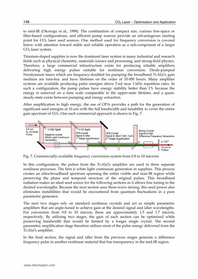
After amplification to high energy, the use of OPA provides a path for the generation of significant seed energies at 10 µm with the full bandwidth and tunability to cover the entire gain spectrum of CO2. One such commercial approach is shown in Fig. 7.
Fig. 7. Commercially-available frequency conversion system from 0.8 to 10 microns
In this configuration, the pulses from the Ti:Al2O3 amplifier are used in three separate nonlinear processes. The first is white light continuum generation in sapphire. This process creates an ultra-broadband spectrum spanning the entire visible and near-IR region while preserving the phase and temporal structure of the original pulses. This broadband radiation makes an ideal seed source for the following sections as it allows free tuning to the desired wavelengths. Because the next section uses three-wave mixing, this seed power also eliminates instabilities that would be encountered from quantum fluctuations in a pure parametric generator.
The next two stages rely on standard nonlinear crystals and act as simple parametric amplifiers that are angle-tuned to achieve gain at the desired signal and idler wavelengths. For conversion from 0.8 to 10 micron, these are approximately 1.5 and 1.7 micron, respectively. By utilizing two stages, the gain of each section can be optimized while preserving bandwidth that would be limited by a longer single crystal. The second parametric amplification stage therefore utilizes most of the pulse energy delivered from the Ti:Al2O3 amplifier.
In the final section, the signal and idler from the previous stages generate a difference frequency pulse in another nonlinear material that has transparency in the mid-IR region.
www.intechopen.com
Ultrashort Pulses
147
These cascaded nonlinear processes allow stable, repeatable conversion of the ultrafast pump pulses from the near- to the mid-IR region, while providing broad bandwidth, wavelength tunability, and ultrashort duration. The theoretical maximum energy conversion efficiency from 0.8 to 10 micron via this cascaded three-photon mixing is near 3.5%, however when real beams which are non-uniform in time and space are considered, as well as losses on the large number of optical elements required, the realized efficiency is approximately an order of magnitude lower. Pulsewidths under 500 fs are easily achievable, as well as bandwidth covering any single branch of the CO2 gain spectrum.
All-solid-state systems provide good control of pulse synchronization and shape, but are much more elaborate than the other techniques used for ultrashort mid-IR pulse generation.
3. Amplification
3.1 “Smoothing” the gain spectrum
A major problem in seamlessly amplifying picosecond pulses is the discrete rotational-line structure of the gain spectrum, causing modulation of the pulse spectrum and pulse splitting. The gain spectrum’s modulation can be smeared either by broadening individual rotational lines, thus assuring their better overlap, or by increasing their density. In the first case, we can use pressure- (collision-) and/or field- (power-) broadening effects. Several approaches increase line density: (1) Using an R-branch of a laser transition having a 1.4 times denser line structure than a conventional P-branch; (2) isotopic enrichment of the CO2 molecules, wherein the superposition of the slightly shifted spectra of different isotopic species (isotopologues) generates a denser effective spectrum; and, (3) combining the sequence bands of laser transition with regular ones. We briefly overview these approaches next.
Pressure broadening. As discussed in the Section 1.2, increasing the pressure lowers modulation in the gain spectrum. Complete suppression occurs when collisionally broadened bandwidths of the rotational lines become about twice the interline distance. However, the 20-25 bar pressure required for this, according to the Eq. (3), is impractical due to difficulties in arranging the uniform electric-discharge pumping the large volume of active gas required for building a high-power CO2 laser amplifier. Replacing discharge- with optical- pumping may afford using a pure-CO2 active medium and increased working pressure, thus considerably extending the pressure broadening effect. Rapid progress in the solid-state laser technology might well lead to the availability of a reliable source for optical excitation of CO2 active medium in the near future. Gordienko & Platonenko, (2010) consider that here the ErCr:YSGG (2.79 µm) laser is a promising candidate.
Field broadening. We can approximate the magnitude of line broadening (FWHM) appearing in the intense laser field due to the Autler-Townes (or dynamic Stark) effect (Autler &
Townes, 1955) by the doubled Rabi frequency ┑: Δ 2 2fieldν d E=
h= Ω
⋅, where d is the
transition dipole momentum, E is the laser field, and h is Plank's constant. Substituting the laser field with its expression through the intensity, I, and using the numerical values of the involved constants, we get the following equation:
20.02764 [D] [W/Δ [G cm ]Hz]field d Iν ≈ (5)
www.intechopen.com
CO2 Laser – Optimisation and Application
148
With Eq. (5), and the known value of the laser’s transition dipole momentum d=0.0275 D (the value for the 10P(20) line from HITRAN database (Rothman et al., 2009)), we find that field broadening is sufficient to completely suppress modulation at a laser intensity 15-20 GW/cm2; this is reachable in the modern high-power picosecond CO2 laser systems. Capitalizing on this approach supported the attainment of 15 TW peak power in the CO2 laser system of Neptune Laboratory of the University of California, Loss Angeles (Section 6.2).
R-branch. The R-branches of the CO2 laser transitions have a rotational structure 1.4 times denser than the more often used P-branches (Witteman, 1987); thus, they offer better overlap between collisionally broadened lines, and, hence, yield a smoother gain spectrum (Fig. 2). Interestingly, under high-pressure conditions, such as 10 bar or higher, the overlap between rotational lines increases the peak intensity of the R-branch compared to that of the P-branch that otherwise prevails in conventional low-pressure lasers.
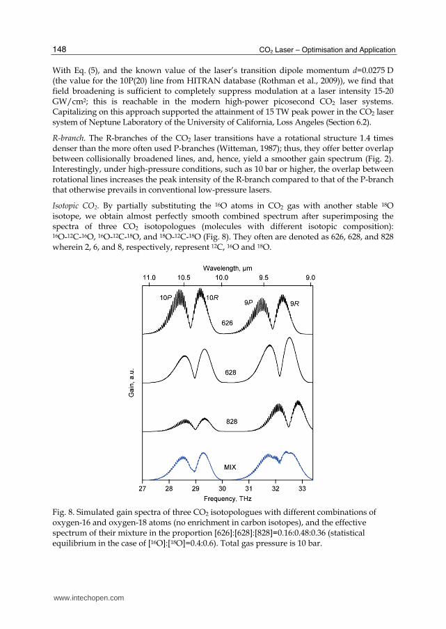
Isotopic CO2. By partially substituting the 16O atoms in CO2 gas with another stable 18O isotope, we obtain almost perfectly smooth combined spectrum after superimposing the spectra of three CO2 isotopologues (molecules with different isotopic composition): 16O-12C-16O, 16O-12C-18O, and 18O-12C-18O (Fig. 8). They often are denoted as 626, 628, and 828 wherein 2, 6, and 8, respectively, represent 12C, 16O and 18O.
Fig. 8. Simulated gain spectra of three CO2 isotopologues with different combinations of oxygen-16 and oxygen-18 atoms (no enrichment in carbon isotopes), and the effective spectrum of their mixture in the proportion [626]:[628]:[828]=0.16:0.48:0.36 (statistical equilibrium in the case of [16O]:[18O]=0.4:0.6). Total gas pressure is 10 bar.
www.intechopen.com
Ultrashort Pulses
149
For a given proportion [16O]:[18O], independent of the initial distribution of 16O and 18O between the CO2 molecules, statistical equilibration via intermolecular isotope-exchange leads to [626]:[628]:[828]= [16O]2:2[16O] [18O]:[18O]2. We note that due to the broken symmetry of the 628 molecule, it has twice as many rotational lines in each rotational branch compared to more symmetric 626- and 828- isotopologues. The combination of three CO2 isotopologues, as depicted in Fig. 8, results in a smooth spectrum already apparent at 10 bar. The gain of the isotopic mixture in the 10-micron branches at this pressure is 1.4 times lower than that of the regular gas, mainly reflecting the relatively low gain of the 828 CO2 isotopologue. Thus, a longer path through an active medium or a higher CO2 concentration is needed to maintain the same net amplification. The isotope-based approach is practically implemented in the CO2 laser of Accelerator Test Facility at Brookhaven National Laboratory (Section 6.1).
Sequence bands. Transitions between high-lying vibrational overtones of the CO2 molecule can contribute considerably to the high-pressure amplifier gain. In this case, the rotational spectra of the regular- and sequence- bands overlap, so providing a denser effective spectrum. Exploiting the sequence band for smoothing the gain spectrum seems especially promising for the 10R branch wherein the rotational lines belonging to the sequence band 0002-[1001,0201]I fall very close to the centers of the gaps between the lines of the regular band 0001-[1000,0200]I. Simple estimation of the ratio of gains of the sequence- and the regular- band, assuming the Boltzmann energy distribution within a vibrational mode (Reid & Siemsen, 1976):
3 3/ 2 exp( / )seq regG G h kTν= − , (6)
where T3 and ν3 are the vibrational temperature and frequency of the asymmetric stretch- mode of the CO2 molecule, and h and k respectively are the Plank’s and Boltzmann’s constants, show that sequence band’s gain reaches 50% of the regular band’s gain at T3=2500 K, viz., comparable to the conditions of high-pressure CO2 amplifiers.
3.2 Effects in optical materials
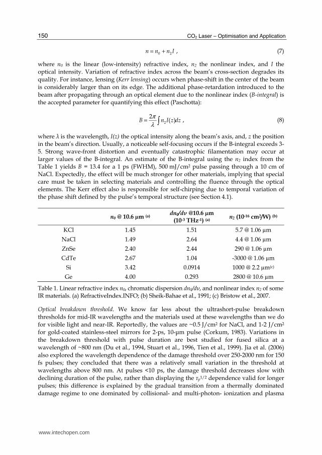
To assure highly intense laser fields, special attention must be given to properly selecting and utilizing the optical elements, and to accounting for their influence on the laser field. This especially is challenging in the 10-┤m spectral region because of the dearth of optical materials compared to the visible or near-IR diapasons, and lack of data on the materials’ behavior under ultrashort mid-IR pulses. Below, we summarize the properties of optical materials most important for using in the high-peak-power 10-┤m laser field. Table 1 gives numerical data on the refractive indices and dispersion of some popular IR materials used in CO2 lasers.
Chromatic dispersion plays an important role due to the hundreds of GHz-wide spectrum of (sub-) picosecond 10-┤m pulses that may entail considerable pulse stretching. For example, a pulse of 1 ps (FWHM) spreads to 1.27 ps after a single pass through a 10-cm NaCl window. Accordingly, the amount and thickness of optical elements should be minimized, and/or a grating compensator added for recompressing the pulse.
Nonlinear index, B-integral. A high-power laser pulse propagating through a medium changes its refractive index n (the Kerr effect):
www.intechopen.com
CO2 Laser – Optimisation and Application
150
0 2n n n I= + , (7)
where n0 is the linear (low-intensity) refractive index, n2 the nonlinear index, and I the
optical intensity. Variation of refractive index across the beam’s cross-section degrades its
quality. For instance, lensing (Kerr lensing) occurs when phase-shift in the center of the beam
is considerably larger than on its edge. The additional phase-retardation introduced to the
beam after propagating through an optical element due to the nonlinear index (B-integral) is
the accepted parameter for quantifying this effect (Paschotta):
2
2( )B n I z dz
π
λ= , (8)
where λ is the wavelength, I(z) the optical intensity along the beam’s axis, and, z the position in the beam’s direction. Usually, a noticeable self-focusing occurs if the B-integral exceeds 3-5. Strong wave-front distortion and eventually catastrophic filamentation may occur at larger values of the B-integral. An estimate of the B-integral using the n2 index from the Table 1 yields B = 13.4 for a 1 ps (FWHM), 500 mJ/cm2 pulse passing through a 10 cm of NaCl. Expectedly, the effect will be much stronger for other materials, implying that special care must be taken in selecting materials and controlling the fluence through the optical elements. The Kerr effect also is responsible for self-chirping due to temporal variation of the phase shift defined by the pulse’s temporal structure (see Section 4.1).
n0 @ 10.6 µm (a) dn0/dν @10.6 µm
(10-3 THz-1) (a) n2 (10-16 cm2/W) (b)
KCl 1.45 1.51 5.7 @ 1.06 µm
NaCl 1.49 2.64 4.4 @ 1.06 µm
ZnSe 2.40 2.44 290 @ 1.06 µm
CdTe 2.67 1.04 -3000 @ 1.06 µm
Si 3.42 0.0914 1000 @ 2.2 µm(c)
Ge 4.00 0.293 2800 @ 10.6 µm
Table 1. Linear refractive index n0, chromatic dispersion dn0/dν, and nonlinear index n2 of some IR materials. (a) RefractiveIndex.INFO; (b) Sheik-Bahae et al., 1991; (c) Bristow et al., 2007.
Optical breakdown threshold. We know far less about the ultrashort-pulse breakdown
thresholds for mid-IR wavelengths and the materials used at these wavelengths than we do
for visible light and near-IR. Reportedly, the values are ~0.5 J/cm2 for NaCl, and 1-2 J/cm2
for gold-coated stainless-steel mirrors for 2-ps, 10-┤m pulse (Corkum, 1983). Variations in
the breakdown threshold with pulse duration are best studied for fused silica at a
wavelength of ~800 nm (Du et al., 1994, Stuart et al., 1996, Tien et al., 1999). Jia et al. (2006)
also explored the wavelength dependence of the damage threshold over 250-2000 nm for 150
fs pulses; they concluded that there was a relatively small variation in the threshold at
wavelengths above 800 nm. At pulses <10 ps, the damage threshold decreases slow with
declining duration of the pulse, rather than displaying the τp1/2 dependence valid for longer
pulses; this difference is explained by the gradual transition from a thermally dominated
damage regime to one dominated by collisional- and multi-photon- ionization and plasma
www.intechopen.com
Ultrashort Pulses
151
formation. Assuming a similar behavior in mid-IR, we conclude there is relatively small
variation of the breakdown threshold fluence as a function of pulse duration for pulses of a
few picoseconds or shorter; thus, as a guideline in system design, in most cases we can
adopt 0.5 J/cm2 for transparent optics, and 1 J/cm2 for mirrors.
3.3 Chirped-pulse amplification
We can minimize the high-power effects in optical materials on the pulse by employing the
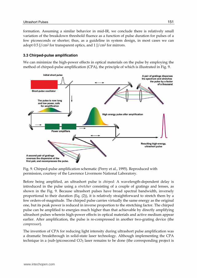
method of chirped-pulse amplification (CPA), the principle of which is illustrated in Fig. 9.
Fig. 9. Chirped-pulse amplification schematic (Perry et al., 1995). Reproduced with permission, courtesy of the Lawrence Livermore National Laboratory.
Before being amplified, an ultrashort pulse is chirped: A wavelength-dependent delay is
introduced in the pulse using a stretcher consisting of a couple of gratings and lenses, as
shown in the Fig. 9. Because ultrashort pulses have broad spectral bandwidth, inversely
proportional to their duration (Eq. (2)), it is relatively straightforward to stretch them by a
few orders-of-magnitude. The chirped pulse carries virtually the same energy as the original
one, but its peak power is reduced in inverse proportion to the stretching factor. The chirped
pulse can be amplified to energies much higher than that achievable by directly amplifying
ultrashort pulses wherein high-power effects in optical materials and active medium appear
earlier. After amplification, the pulse is re-compressed in another two-grating device (the
compressor).
The invention of CPA for reducing light intensity during ultrashort pulse amplification was
a dramatic breakthrough in solid-state laser technology. Although implementing the CPA
technique in a (sub-)picosecond CO2 laser remains to be done (the corresponding project is
www.intechopen.com
CO2 Laser – Optimisation and Application
152
planned at the Accelerator Test Facility of the Brookhaven National Laboratory), it is
reasonable to expect that the outcome will comparably be valuable.
3.4 Energy extraction efficiency
Optimal use of the energy stored in the active medium is a key characteristic of a mature
laser design. The difficulty in efficiently extracting excitation energy from gaseous active
media via an ultrashort pulse arises from the fact that the pulse’s duration is either shorter
than, or comparable to the characteristic times of the involved excitation- and relaxation-
processes. Below, we briefly consider these processes and their influence on the efficiency of
extracting energy.
Excitation and vibrational relaxation. In a typical CO2 laser, an electric discharge is used to
create population inversion. Fast electrons accelerated by electric field collide with CO2 and
N2 molecules, so exciting their upper vibrational states. Nitrogen serves as reservoir for
storing the excitation energy which is then transferred to CO2 via vibrational relaxation. The
typical duration of discharge in a pulsed CO2 laser is about a microsecond, and vibrational
relaxation times range from 1-10 ns·bar. This implies that a (sub-)picosecond laser pulse only
extracts energy already available at the upper vibrational laser-level, with negligible energy
deposition from the discharge or from redistribution from other vibrational levels during
pulse propagation. To maximize extraction, wherever possible a regenerative amplification
scheme is used, wherein the pulse passes the amplifier medium many times allowing
repopulation of the upper vibrational level of the laser transition between the passes.
However, realizing this scheme practically is problematic for high-energy pulses when
beam must be wide to increase the active volume and avoid damaging optical elements.
Thus, two-stage amplification usually is adopted (see Section 6); a regenerative amplifier
providing amplification up to millijoules level is followed by a final high-energy amplifier
arranged either in a single-pass configuration, or several passes are only partially
overlapped. Slow pumping and vibrational relaxation limit energy extraction in the final
amplification stage. A possible solution is replacing pumping by electric discharge, with
optical pumping by a short laser pulse that quickly and directly excites the upper laser level,
and eliminates the need for redistributing vibrational energy.
Rotational relaxation. Rotational relaxation processes limit the fraction of energy extractable
from the upper vibrational laser level in a single pass through the active medium. The laser
pulse interacts only with a limited number of rotational transitions that is defined by the
overlap between the pulse’s spectrum and the amplification band. At high pressure, when
collisionally broadened rotational lines overlap, or for a very short pulse, when pulse’s
spectrum covers several rotational lines, energy is extracted from several rotational sub-
levels. Otherwise, energy is extracted only from a single sub-level containing about 1/15th of
the entire energy stored in that vibrational level. Three scenarios support the complete
emptying of the vibrational level: (1) The pulse is long enough to provide time for
repopulation of the active rotational levels. Typical rotational relaxation times are
~100 ps·bar; about 15 collisions are required effectively to empty all rotational sub-levels
through a single active rotational transition. Thus, the minimum required pulse duration is
~1.5 ns·bar (e.g., 150 ps at 10 bar). (2) Pressure broadening allows all rotational transitions to
interact with the laser field. Using Eq. (3) we find that ~100 bar is needed to broaden the
www.intechopen.com
Ultrashort Pulses
153
rotational lines to the ~0.5 THz necessary for this regime. (3) The spectrum of the pulse
covers the entire rotational branch, as happens when the pulse duration is ≤1 ps (Eq. (2)).
The last regime is preferable if the aim is to keep pulse’s span as brief as possible.
4. Pulse compression
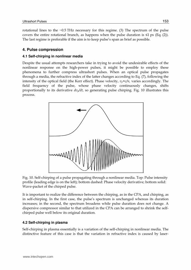
4.1 Self-chirping in nonlinear media
Despite the usual attempts researchers take in trying to avoid the undesirable effects of the
nonlinear response on the high-power pulses, it might be possible to employ these
phenomena to further compress ultrashort pulses. When an optical pulse propagates
through a media, the refractive index of the latter changes according to Eq. (7), following the
intensity of the optical field (the Kerr effect). Phase velocity, vp=c/n, varies accordingly. The
field frequency of the pulse, whose phase velocity continuously changes, shifts
proportionally to its derivative dvp/dt, so generating pulse chirping. Fig. 10 illustrates this
process.
Fig. 10. Self-chirping of a pulse propagating through a nonlinear media. Top: Pulse intensity profile (leading edge is on the left); bottom dashed: Phase velocity derivative; bottom solid: Wave-packet of the chirped pulse.
It is important to realize the difference between the chirping, as in the CPA, and chirping, as
in self-chirping. In the first case, the pulse’s spectrum is unchanged whereas its duration
increases; in the second, the spectrum broadens while pulse duration does not change. A
dispersive compressor similar to that utilized in the CPA can be arranged to shrink the self-
chirped pulse well below its original duration.
4.2 Self-chirping in plasma
Self-chirping in plasma essentially is a variation of the self-chirping in nonlinear media. The
distinctive feature of this case is that the variation in refractive index is caused by laser-
www.intechopen.com
CO2 Laser – Optimisation and Application
154
induced gas-ionization rather than the Kerr effect. Refractive index of the ionized gas is
determined by the linear refractive index of the media, n0, and the plasma density, Ne:
1/2
0 1 e
c
Nn n
N
= − , (9)
where Nc is the critical density (Eq. (1)). Unlike the Kerr effect, where refractive index
usually increases with laser intensity, strong ionization in high-intensity fields decreases the
refractive index. Therefore, the direction of chirping is reversed: The field frequency of the
leading edge of the pulse is higher than that of the trailing one (blue chirp), allowing the
compression of the chirped pulse via the linear dispersion in an optical material. By sending
the pulse through a window of a properly selected thickness, made of a material with
negative group velocity dispersion (e.g., NaCl), we can delay the blue-shifted leading edge
of the pulse more than the trailing edge, thus shrinking the pulse.
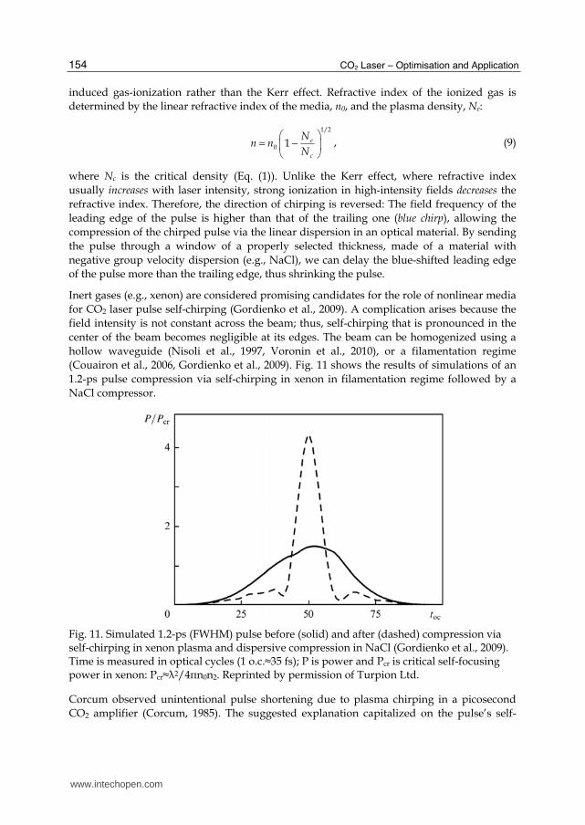
Inert gases (e.g., xenon) are considered promising candidates for the role of nonlinear media
for CO2 laser pulse self-chirping (Gordienko et al., 2009). A complication arises because the
field intensity is not constant across the beam; thus, self-chirping that is pronounced in the
center of the beam becomes negligible at its edges. The beam can be homogenized using a
hollow waveguide (Nisoli et al., 1997, Voronin et al., 2010), or a filamentation regime
(Couairon et al., 2006, Gordienko et al., 2009). Fig. 11 shows the results of simulations of an
1.2-ps pulse compression via self-chirping in xenon in filamentation regime followed by a
NaCl compressor.
Fig. 11. Simulated 1.2-ps (FWHM) pulse before (solid) and after (dashed) compression via self-chirping in xenon plasma and dispersive compression in NaCl (Gordienko et al., 2009). Time is measured in optical cycles (1 o.c.≈35 fs); P is power and Pcr is critical self-focusing power in xenon: Pcr≈┣2/4πn0n2. Reprinted by permission of Turpion Ltd.
Corcum observed unintentional pulse shortening due to plasma chirping in a picosecond
CO2 amplifier (Corcum, 1985). The suggested explanation capitalized on the pulse’s self-
www.intechopen.com
Ultrashort Pulses
155
chirping in the partially ionized active media, and compression in the material of the cavity
windows. Controlled shortening was realized using an external gas cell by Tochitsky et al.
(Tochitsky et al., 2001).
5. Pulse diagnostics
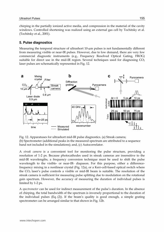
Measuring the temporal structure of ultrashort 10-µm pulses is not fundamentally different from measuring visible or near-IR pulses. However, due to low demand, there are very few commercial diagnostic instruments (e.g., Frequency Resolved Optical Gating, FROG) suitable for direct use in the mid-IR region. Several techniques used for diagnosing CO2 laser pulses are schematically represented in Fig. 12.
Fig. 12. Apparatuses for ultrashort mid-IR pulse diagnostics. (a) Streak camera; (b) Spectrometer (additional peaks in the measured spectrum are attributed to a sequence band not included in the simulations); and, (c) Autocorrelator.
A streak camera is a convenient tool for monitoring the pulse structure, providing a
resolution of 1-2 ps. Because photocathodes used in streak cameras are insensitive to the
mid-IR wavelengths, a frequency conversion technique must be used to shift the pulse
wavelength to the visible- or near-IR- diapason. For this purpose, either a difference-
frequency mixing in a nonlinear crystal (Fig. 12a), or a Kerr-cell-based optical switch where
the CO2 laser’s pulse controls a visible or mid-IR beam is suitable. The resolution of the
streak camera is sufficient for measuring pulse splitting due to modulation on the rotational
gain spectrum. However, the accuracy of measuring the duration of individual pulses is
limited by 1-2 ps.
A spectrometer can be used for indirect measurement of the pulse’s duration. In the absence
of chirping, the total bandwidth of the spectrum is inversely proportional to the duration of
the individual pulses (Eq. (2)). If the beam’s quality is good enough, a simple grating
spectrometer can be arranged similar to that shown in Fig. 12b.
www.intechopen.com
CO2 Laser – Optimisation and Application
156
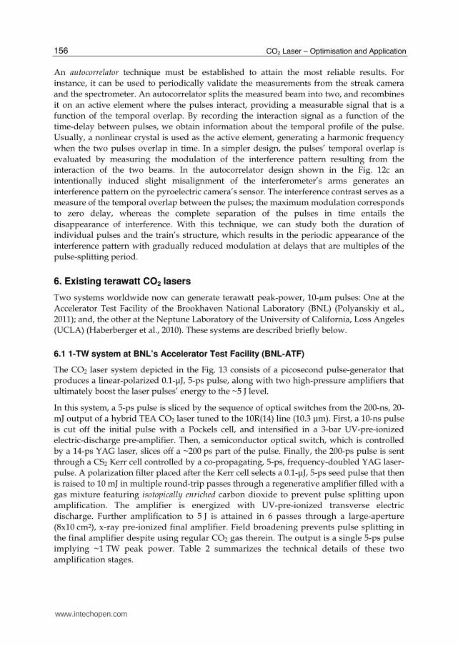
An autocorrelator technique must be established to attain the most reliable results. For
instance, it can be used to periodically validate the measurements from the streak camera
and the spectrometer. An autocorrelator splits the measured beam into two, and recombines
it on an active element where the pulses interact, providing a measurable signal that is a
function of the temporal overlap. By recording the interaction signal as a function of the
time-delay between pulses, we obtain information about the temporal profile of the pulse.
Usually, a nonlinear crystal is used as the active element, generating a harmonic frequency
when the two pulses overlap in time. In a simpler design, the pulses’ temporal overlap is
evaluated by measuring the modulation of the interference pattern resulting from the
interaction of the two beams. In the autocorrelator design shown in the Fig. 12c an
intentionally induced slight misalignment of the interferometer’s arms generates an
interference pattern on the pyroelectric camera’s sensor. The interference contrast serves as a
measure of the temporal overlap between the pulses; the maximum modulation corresponds
to zero delay, whereas the complete separation of the pulses in time entails the
disappearance of interference. With this technique, we can study both the duration of
individual pulses and the train’s structure, which results in the periodic appearance of the
interference pattern with gradually reduced modulation at delays that are multiples of the
pulse-splitting period.
6. Existing terawatt CO2 lasers
Two systems worldwide now can generate terawatt peak-power, 10-µm pulses: One at the
Accelerator Test Facility of the Brookhaven National Laboratory (BNL) (Polyanskiy et al.,
2011); and, the other at the Neptune Laboratory of the University of California, Loss Angeles
(UCLA) (Haberberger et al., 2010). These systems are described briefly below.
6.1 1-TW system at BNL’s Accelerator Test Facility (BNL-ATF)
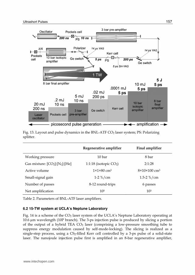
The CO2 laser system depicted in the Fig. 13 consists of a picosecond pulse-generator that produces a linear-polarized 0.1-┤J, 5-ps pulse, along with two high-pressure amplifiers that ultimately boost the laser pulses’ energy to the ~5 J level.
In this system, a 5-ps pulse is sliced by the sequence of optical switches from the 200-ns, 20-
mJ output of a hybrid TEA CO2 laser tuned to the 10R(14) line (10.3 ┤m). First, a 10-ns pulse
is cut off the initial pulse with a Pockels cell, and intensified in a 3-bar UV-pre-ionized
electric-discharge pre-amplifier. Then, a semiconductor optical switch, which is controlled
by a 14-ps YAG laser, slices off a ~200 ps part of the pulse. Finally, the 200-ps pulse is sent
through a CS2 Kerr cell controlled by a co-propagating, 5-ps, frequency-doubled YAG laser-
pulse. A polarization filter placed after the Kerr cell selects a 0.1-┤J, 5-ps seed pulse that then
is raised to 10 mJ in multiple round-trip passes through a regenerative amplifier filled with a
gas mixture featuring isotopically enriched carbon dioxide to prevent pulse splitting upon
amplification. The amplifier is energized with UV-pre-ionized transverse electric
discharge. Further amplification to 5 J is attained in 6 passes through a large-aperture
(8x10 cm2), x-ray pre-ionized final amplifier. Field broadening prevents pulse splitting in
the final amplifier despite using regular CO2 gas therein. The output is a single 5-ps pulse
implying ~1 TW peak power. Table 2 summarizes the technical details of these two
amplification stages.
www.intechopen.com
Ultrashort Pulses
157
Fig. 13. Layout and pulse dynamics in the BNL-ATF CO2 laser system; PS: Polarizing splitter.
Regenerative amplifier Final amplifier
Working pressure 10 bar 8 bar
Gas mixture: [CO2]:[N2]:[He] 1:1:18 (isotopic CO2) 2:1:28
Active volume 1×1×80 cm3 8×10×100 cm3
Small-signal gain 1-2 %/cm 1.5-2 %/cm
Number of passes 8-12 round-trips 6 passes
Net amplification 105 103
Table 2. Parameters of BNL-ATF laser amplifiers.
6.2 15-TW system at UCLA’s Neptune Laboratory
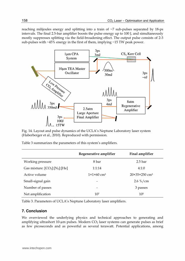
Fig. 14 is a scheme of the CO2 laser system of the UCLA’s Neptune Laboratory operating at 10.6 µm wavelength (10P branch). The 3-ps injection pulse is produced by slicing a portion of the output of a hybrid TEA CO2 laser (comprising a low-pressure smoothing tube to suppress energy modulation caused by self-mode-locking). The slicing is realized as a single-step process, using a CS2-filled Kerr cell controlled by a 3-ps pulse of a solid-state laser. The nanojoule injection pulse first is amplified in an 8-bar regenerative amplifier,
www.intechopen.com
CO2 Laser – Optimisation and Application
158
reaching milijoules energy and splitting into a train of ~7 sub-pulses separated by 18-ps intervals. The final 2.5-bar amplifier boosts the pulse energy up to 100 J, and simultaneously mostly suppresses splitting via the field-broadening effect. The output pulse consists of 2-3 sub-pulses with ~45% energy in the first of them, implying ~15 TW peak power.
Fig. 14. Layout and pulse dynamics of the UCLA’s Neptune Laboratory laser system (Haberberger et al., 2010). Reproduced with permission.
Table 3 summarizes the parameters of this system’s amplifiers.
Regenerative amplifier Final amplifier
Working pressure 8 bar 2.5 bar
Gas mixture: [CO2]:[N2]:[He] 1:1:14 4:1:0
Active volume 1×1×60 cm3 20×35×250 cm3
Small-signal gain - 2.6 %/cm
Number of passes - 3 passes
Net amplification 107 105
Table 3. Parameters of UCLA’s Neptune Laboratory laser amplifiers.
7. Conclusion
We overviewed the underlying physics and technical approaches to generating and amplifying ultrashort 10-µm pulses. Modern CO2 laser systems can generate pulses as brief as few picoseconds and as powerful as several terawatt. Potential applications, among
www.intechopen.com
Ultrashort Pulses
159
which are the high-energy physics experiments and the proton acceleration for cancer therapy, call for even higher peak power.
Achievements in solid-state laser technology can help the further development of ultrashort-pulse, high-peak-power CO2 laser systems. Modern solid-state lasers can be directly used in mid-IR systems, e.g., for controlling optical switches, pumping CO2 laser transition, or generating the ultrashort 10-µm seed pulses via nonlinear frequency conversion and parametric amplification. Apart from that, the advanced techniques initially developed for solid-state lasers (e.g. chirped pulse amplification) can be adopted in CO2 laser systems.
8. Acknowledgements
This work is supported by the US DOE contract DE-AC02-98CH10886 and by the BNL Laboratory Directed R&D (LDRD) grant #07-004. The authors are thankful to Sergei Tochitsky from UCLA’s Neptune Laboratory for providing information on the Neptune’s CO2 laser.
9. References
Abrams, R. L. & Wood, O. R. (1971). Characteristics of a mode-locked TEA CO2 laser. Appl. Phys. Lett., Vol.19, No.12, (December 1971), pp. 518-520, ISSN 0003-6951
Alcock, A. J. & Corkum, P. B. (1979). Ultra-fast switching of infrared radiation by laser-produced carriers in semiconductors. Can. J. Phys., Vol.57, No.9, (September 1979), pp. 1280-1290, ISSN 0008-4204
Armstrong, J. A., Bloembergen, N., Ducuing, J. & Pershan, P. S. (1962). Interactions between light waves in a nonlinear dielectric. Phys. Rev., Vol.127,No.6, (September 1962), pp. 1918-1939, ISSN 1943-2879
Autler, S. H. & Townes, C. H. (1955). Stark effect in rapidly varying fields. Phys. Rev., Vol.100,No.2, (October 1955), pp. 703-722, ISSN 1943-2879
Brimacombe, R. K. & Reid, J. (1983). Accurate measurements of pressure-broadened linewidths in a transversely excited CO2 discharge. IEEE J. Quantum Electron., Vol.19, No.11, (November 1983), pp. 1668-1673, ISSN 0018-9197
Bristow, A. D., Rotenberg, N., & van Driel, H. M. (2007). Two-photon absorption and Kerr coefficients of silicon for 850–2200 nm. Appl. Phys. Lett., Vol.90, No.19 (May 2007), p. 191104, ISSN 0003-6951
Corkum, P. B. & Krausz, F. (2007). Attosecond science. Nature Physics., Vol.3, No.6, (June 2007), pp. 381-387, ISSN 1745-2473
Corkum, P. B. (1983). High-power, subpicosecond 10-┤m pulse generation. Opt. Lett., Vol.8, No.10, (October 1983), pp. 514-516, ISSN 0146-9592
Corkum, P. B. (1985). Amplification of picosecond 10 µm pulses in multiatmosphere CO2 lasers. IEEE J. Quantum Electron., Vol.21, No.3, (March 1985), pp. 216-232, ISSN 0018-9197
Couairon, A., Biegert, J., Hauri, C. P., Kornelis, W., Helbing, F. W., Keller, U. & Mysyrowicz, A., F. (2006). Self-compression of ultra-short laser pulses down to one optical cycle by filamentation. J. Modern Opt., Vol.53, No.1-2, (January 2006), pp. 75-85, ISSN 0950–0340
www.intechopen.com
CO2 Laser – Optimisation and Application
160
Du, D., Liu, X., Korn, G., Squier, J., & Mourou, G. (1994). Laser-induced breakdown by impact ionization in SiO2 with pulse widths from 7 ns to 150 fs. Appl. Phys.Lett., Vol.64, No.26 (June 1994), pp. 3071-3073, ISSN 0003-6951
Esirkepov, T., Borghesi, M., Bulanov, S. V., Mourou, G. & Tajima, T. (2004). Highly efficient relativistic-ion generation in the laser-piston regime. Phys. Rev. Lett., Vol.92, No.17 (April 2004), p. 175003, ISSN 0031-9007
Filip, C. V., Narang R., Tochitsky, S. Ya., Clayton, C. E. &. Joshi, C. (2002). Optical Kerr switching technique for the production of a picosecond, multiwavelength CO2 laser pulse. Appl. Opt., Vol.41, No.18, (June 2002), pp. 3743-3747, ISSN 0003-6935
Giordmaine, J. A. & Miller, R. C. (1965). Tunable coherent parametric oscillation in LiNbO3 at optical frequencies. Phys. Rev. Lett., Vol.14, No.24 (June 1965), p. 973-976, ISSN 0031-9007
Gordienko, V. M., & Platonenko, V. T. (2010). Regenerative amplification of picosecond 10-┤m pulses in a high-pressure optically pumped CO2 laser. Quant. Electron., Vol.40, No.12, (December 2009), pp. 1118-1122, ISSN 1063-7818
Gordienko, V. M., Platonenko, V. T. & Sterzhantov, A. F. (2009). Self-action of a high-power 10-┤m laser radiation in gases: control of the pulse duration and generation of hot electrons. Quant. Electron., Vol.39, No.7, (July 2009), pp. 663-668, ISSN 1063-7818
Haberberger, D., Tochitsky, S. & Joshi, C. (2010). Fifteen terawatt picosecond CO2 laser system. Opt. Express, Vol.18, No.17, (August 2010), pp. 17865-17875, ISSN 1094-4087
Houfman, H. & Meyer, J. (1987). Ultrashort CO2 laser pulse generation by square-wave mode locking and cavity dumping. Opt. Lett., Vol.12, No.2, (February 1987), pp. 87-89, ISSN 0146-9592
Jia, T. Q., Chen, H. X., Huang, M., Zhao, F. L., Li, X. X., Xu, S. Z., Sun, H. Y., Feng, D. H., Li, C. B., Wang, X. F., Li, R. X., Xu, Z. Z., He, X. K. & Kuroda, H. (2006). Ultraviolet-infrared femtosecond laser-induced damage in fused silica and CaF2 crystals. Phys. Rev. B, Vol.73, No.5 (February, 2006) p.054105, ISSN 0163-1829
Korzhimanov, A. V., Gonoskov, A. A., Khazanov, E. A. & Sergeev, A. M. (2011). Horizons of petawatt laser technology. Physics - Uspekhi, Vol.54, No.1, (January 2011), pp. 9-28, ISSN 1063-7869
Kovalev, V. I. (1996). Mechanism of self-mode-locking in the active medium of CO2 lasers. Quant. Electron., Vol.26, No.2, (February 1996), pp. 131-132, ISSN 1063-7818
Nisoli, M., Stagira, S., De Silvestri, S., Svelto, O., Sartania, S., Cheng, Z., Lenzner, M., Spielmann, C. & Krausz, F. (1997). A novel high-energy pulse compression system: generation of multigigawatt sub-5-fs pulses. Appl. Phys. B, Vol.65, No.2, (August 1997), pp. 189-196, ISSN 0946-2171
Norreys, P. (2011). Particle acceleration: Pushing protons with photons. Nature Photonics, Vol.5, No.3, (March 2011), pp. 134-135, ISSN 1749-4885
Okorogu, A. O., Mirov, S. B., Lee, W., Crouthamel, D. I., Jenkins, N., Dergachev, A. Yu., Vodopyanov, K. L. & Badikov, V. V. (1998). Tunable middle infrared downconversion in GaSe and AgGaS2. Opt. Commun., Vol.155, No.4-6, (October 1998), pp. 307-312, ISSN 0030-4018
Palmer, C. A. J., Dover, N. P., Pogorelsky, I., Babzien, M., Dudnikova, G. I., Ispiriyan, M., Polyanskiy, M. N., Schreiber, J., Shkolnikov, P., Yakimenko, V. & Najmudin, Z.
www.intechopen.com
Ultrashort Pulses
161
(2011). Monoenergetic proton beams accelerated by a radiation pressure driven shock. Phys. Rev. Lett., Vol.106, No.1 (January 2011), p. 014801, ISSN 0031-9007
Paschotta, R. (2008). Field Guide to Laser Pulse Generation, SPIE Press, ISBN 978-0-8194-7248-9, Bellingham, Washington, USA
Paschotta, R.. B-Integral. Encyclopedia of laser physics and technology. Available from: http://www.rp-photonics.com/b_integral.html. Accessed October 6, 2011
Perry, M., Shore, B., Boyd, R. & Britten, J. (1995). Multilayer dielectric gratings: Increasing the power of light. LLNL Sci. Technol. Rev., (September 1995), pp. 24-33
Polyanskiy, M. N., Pogorelsky, I. V. & Yakimenko, V. (2011). Picosecond pulse amplification in isotopic CO2 active medium. Opt. Express, Vol.19, No.8, (April 2011), pp. 7717-7725, ISSN 1094-4087
RefractiveIndex.INFO. Refractive index database. Available from http://refractiveindex.info. Accessed September 30, 2011
Reid, J. & Siemsen, K. (1976). New CO2 laser bands in the 9–11-┤m wavelength region. Appl. Phys. Lett., Vol.29, No.4 (August 1976), pp. 250-251, ISSN 0003-6951
Rolland, C. & Corkum, P. B. (1986). Generation of 130-fsec midinfrared pulses. J. Opt. Soc. Am. B, Vol.3, No.12, (December 1986), pp. 1625-1629, ISSN 0740-3224
Rothman, L. S., Gordon, I. E., Barbe, A. et al. (2009) The HITRAN 2008 molecular spectroscopic database. J. Quant. Spectr. Rad. Transfer, Vol.110, No.9-10 (June-July 2009), pp. 533-572, ISSN: 0022-4073
Sheik-Bahae, M., Hutchings, D. C., Hagan, D. J. & Van Stryland, E. W. (1991). Dispersion of bound electron nonlinear refraction in solids. IEEE J. Quantum Electron., Vol.27, No.6, (June 1991), pp. 1296-1309, ISSN 0018-9197
Siegman, A. E. & Kuizenga, D. J. (1969). Simple analytical expressions for AM and FM mode-locked pulses in homogeneous lasers. Appl. Phys. Lett., Vol.14, No.6, (March 1969), pp. 518-520, ISSN 0003-6951
Stuart, B. C., Feit, M. D., Rubenchik, A. M., Shore, B. W., and Perry, M. D. (1996). Nanosecond-to-femtosecond laser-induced breakdown in dielectrics. Phys. Rev. B, Vol.53, No.4, (January 1996), pp. 1749-1761, ISSN 0163-1829
Tien, A.-C., Backus, S., Kapteyn, H., Murnane M., & Mourou G. (1999). Short-pulse laser damage in transparent materials as a function of pulse duration. Phys. Rev. Lett., Vol.82, No.19 (May 1999), pp. 3883-3886, ISSN 0031-9007
Tochitsky, S. Ya., Filip, C., Narang, R., Clayton, C. E., Marsh, K. A. & Joshi, C. (2001). Efficient shortening of self-chirped picosecond pulses in a high-power CO2 amplifier. Opt. Lett., Vol.26, No.11, (June 2001), pp. 813-815, ISSN 0146-9592
Voronin, A. A., Gordienko, V. M., Platonenko, V. T., Panchenko, V. Ya. & Zheltikov, A. M. (2010). Ionization-assisted guided-wave pulse compression to extreme peak powers and single-cycle pulse widths in the mid-infrared. Opt. Lett., Vol.35, No.21, (November 2010), pp. 3640-3642, ISSN 0146-9592
Witteman, W. J. (1987). The CO2 laser. Springer-Verlag, ISBN 0-387-17657-8, Berlin Heidelberg New York London Paris Tokyo
Wood, O. R., Abrams R. L. & Bridges, T. J. (1970). Mode locking of a transversively excited atmospheric pressure CO2 Laseer. Appl. Phys. Lett., Vol.17, No.9, (November 1970), pp. 376-378, ISSN 0003-6951
www.intechopen.com
CO2 Laser – Optimisation and Application
162
Yablonovich, E. (1973). Spectral broadening in the light transmitted through a rapidly growing plasma. Phys. Rev. Lett., Vol.31, No.14, (October 1973), pp. 877–879, ISSN 0031-9007
Yablonovich, E. (1974a). Short CO2 laser pulse generation by optical free induction decay. Appl. Phys. Lett., Vol.25, No.10, (November 1974), pp. 580-582, ISSN 0003-6951
Yablonovich, E. (1974b). Self-phase modulation and short-pulse generation from laser-breakdown plasmas. Phys. Rev. A, Vol.10, No.5, (November 1974), pp. 1888-1895, ISSN 1050-2947
Yakimenlo, V. & Pogorelsky, I. (2006). Polarized γ source based on Compton backscattering in a laser cavity. Phys. Rev. ST Accel. Beams, Vol.9, No.9, (September 2006), p. 091001, ISSN 1098-4402
www.intechopen.com
CO2 Laser - Optimisation and ApplicationEdited by Dr. Dan C. Dumitras
ISBN 978-953-51-0351-6Hard cover, 436 pagesPublisher InTechPublished online 21, March, 2012Published in print edition March, 2012
InTech EuropeUniversity Campus STeP Ri Slavka Krautzeka 83/A 51000 Rijeka, Croatia Phone: +385 (51) 770 447 Fax: +385 (51) 686 166www.intechopen.com
InTech ChinaUnit 405, Office Block, Hotel Equatorial Shanghai No.65, Yan An Road (West), Shanghai, 200040, China
Phone: +86-21-62489820 Fax: +86-21-62489821
The present book includes several contributions aiming a deeper understanding of the basic processes in theoperation of CO2 lasers (lasing on non-traditional bands, frequency stabilization, photoacoustic spectroscopy)and achievement of new systems (CO2 lasers generating ultrashort pulses or high average power, lasersbased on diffusion cooled V-fold geometry, transmission of IR radiation through hollow core microstructuredfibers). The second part of the book is dedicated to applications in material processing (heat treatment,welding, synthesis of new materials, micro fluidics) and in medicine (clinical applications, dentistry, non-ablativetherapy, acceleration of protons for cancer treatment).
How to referenceIn order to correctly reference this scholarly work, feel free to copy and paste the following:
Mikhail N. Polyanskiy and Marcus Babzien (2012). Ultrashort Pulses, CO2 Laser - Optimisation andApplication, Dr. Dan C. Dumitras (Ed.), ISBN: 978-953-51-0351-6, InTech, Available from:http://www.intechopen.com/books/co2-laser-optimisation-and-application/ultrashort-pulses

© 2012 The Author(s). Licensee IntechOpen. This is an open access articledistributed under the terms of the Creative Commons Attribution 3.0License, which permits unrestricted use, distribution, and reproduction inany medium, provided the original work is properly cited.