The SDHCAL prototype present status & developments · resolution. The high granularity is used for...
15
IPRD 2016 Siena 1 The SDHCAL prototype present status & developments L.Mirabito, IPN Lyon on behalf of CALICE collaboration
Transcript of The SDHCAL prototype present status & developments · resolution. The high granularity is used for...

IPRD 2016 Siena 1
The SDHCAL prototypepresent status & developments
L.Mirabito, IPN Lyonon behalf of CALICE collaboration
2
Brief history of SDHCAL
● 2010-2011– Construction of a 1 m3 technological prototype of HCAL for ILD
● Module : 48 x 1 m2 Glass RPC chambers with 2.2 cm of iron absorber (6 λI)● Semi digital readout ( 1 cm2 pads, 3 thresholds) with power-pulsed electronic● Self-supporting mechanics with embedded absorber
● 2012– First beam test on PS & SPS beam @ cern
● 2014-2015– Second measurement campaign
● improved daq and calibration
● 2016– First ECAL-HCAL beamtest
– Development of larger size detection plan (up to 3 m2)
– Development of new readout and daq system
3
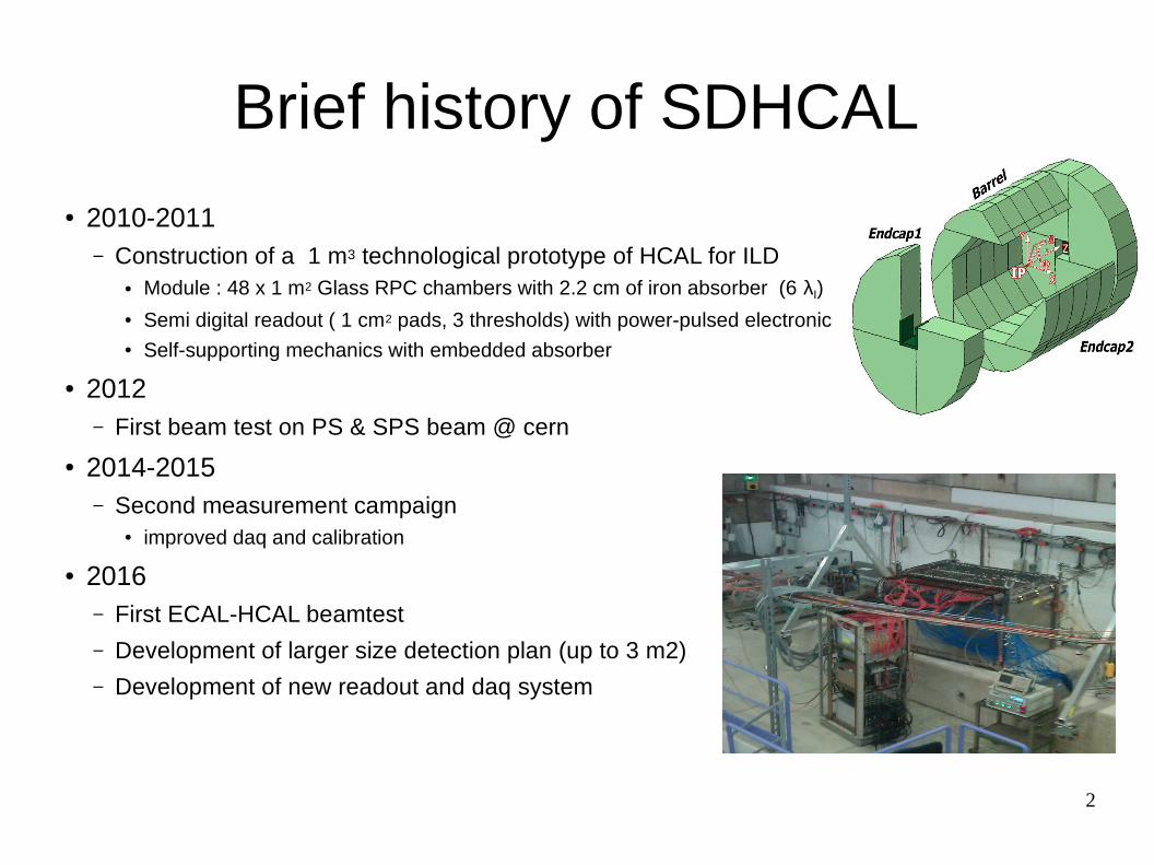
● 10500 ASICs (64 ch Hardroc2 Ω) tested. – 93 % yield
● 310 PCB (24 Asics) produced and tested● 170 DIF (FPGA based,front end interface) ● 50 detectors built , mounted in cassettes, tested and
inserted in self supporting mechanical structure● USB2 readout. Daq based on DIM (data) and web
protocols (control)
Prototype construction
4
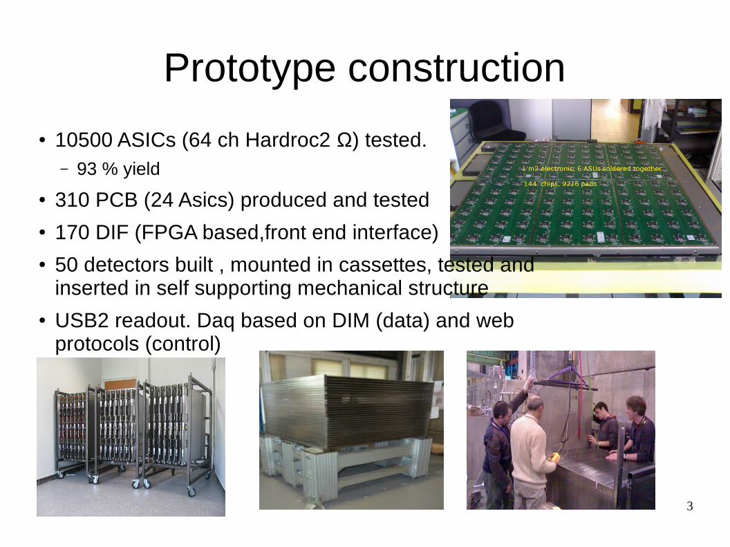
Running condition & Commissioning
● Power pulsing using SPS/PS spill structure– Lateral cooling with cold water (15 oC)
● Self triggering ASICs improved dead-time wrt external trigger● Thresholds → Particle multiplicity / pad● Hadron,electron and muon (efficiency) beams from 1 to 90 GeV/c● RPC nominal settings
– Gas 95 % TFE/ 5 % CO2/ 3% SF6
– HV ~ 6900 V
● Noise ~ 3 Hz/cm2 , MIP ε ~ 96 %, MIP cluster size ~ 1.8● Limitation:
– RPC → rate / cm2 < 100 Hz, i.e shower rate ~ 30 Hz
5
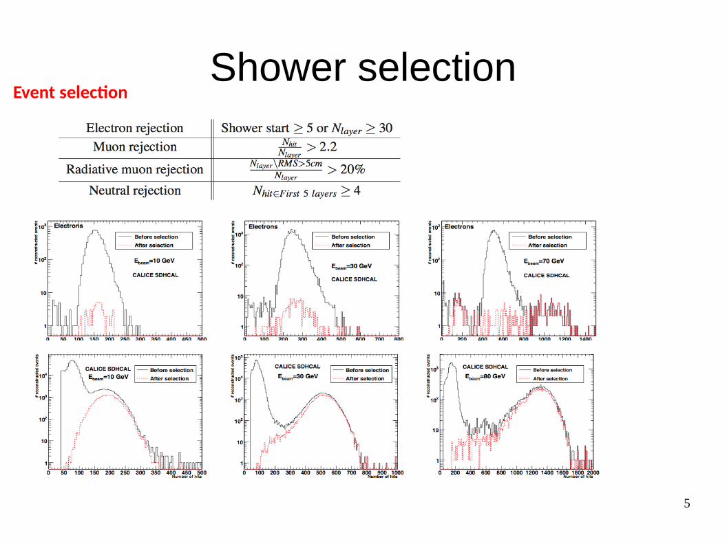
Shower selectionEvent selection
6
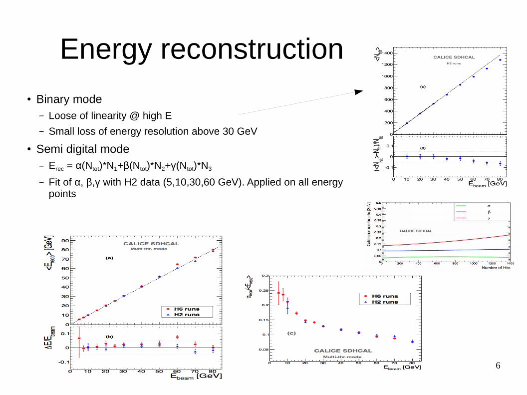
Energy reconstruction
● Binary mode– Loose of linearity @ high E
– Small loss of energy resolution above 30 GeV
● Semi digital mode– Erec = α(Ntot)*N1+β(Ntot)*N2+γ(Ntot)*N3
– Fit of α, β,γ with H2 data (5,10,30,60 GeV). Applied on all energy points
7
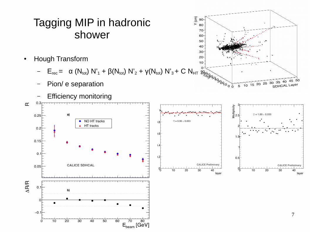
Tagging MIP in hadronic shower
● Hough Transform
– Erec = α (Ntot) N’1 + β(Ntot) N’2 + γ(Ntot) N’3 + C NHT
– Pion/ e separation
– Efficiency monitoring
8
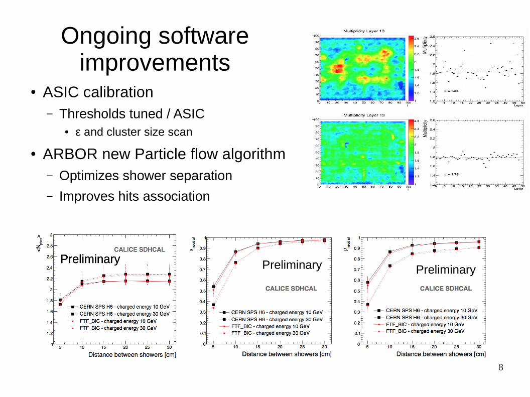
Ongoing software improvements
● ASIC calibration– Thresholds tuned / ASIC
● ε and cluster size scan
● ARBOR new Particle flow algorithm– Optimizes shower separation
– Improves hits association
PreliminaryPreliminary Preliminary Preliminary
9
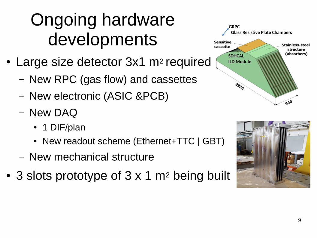
Ongoing hardware developments
● Large size detector 3x1 m2 required– New RPC (gas flow) and cassettes
– New electronic (ASIC &PCB)
– New DAQ ● 1 DIF/plan● New readout scheme (Ethernet+TTC | GBT)
– New mechanical structure
● 3 slots prototype of 3 x 1 m2 being built
SDHCALILD Module
GRPC Glass Resistive Plate Chambers
10
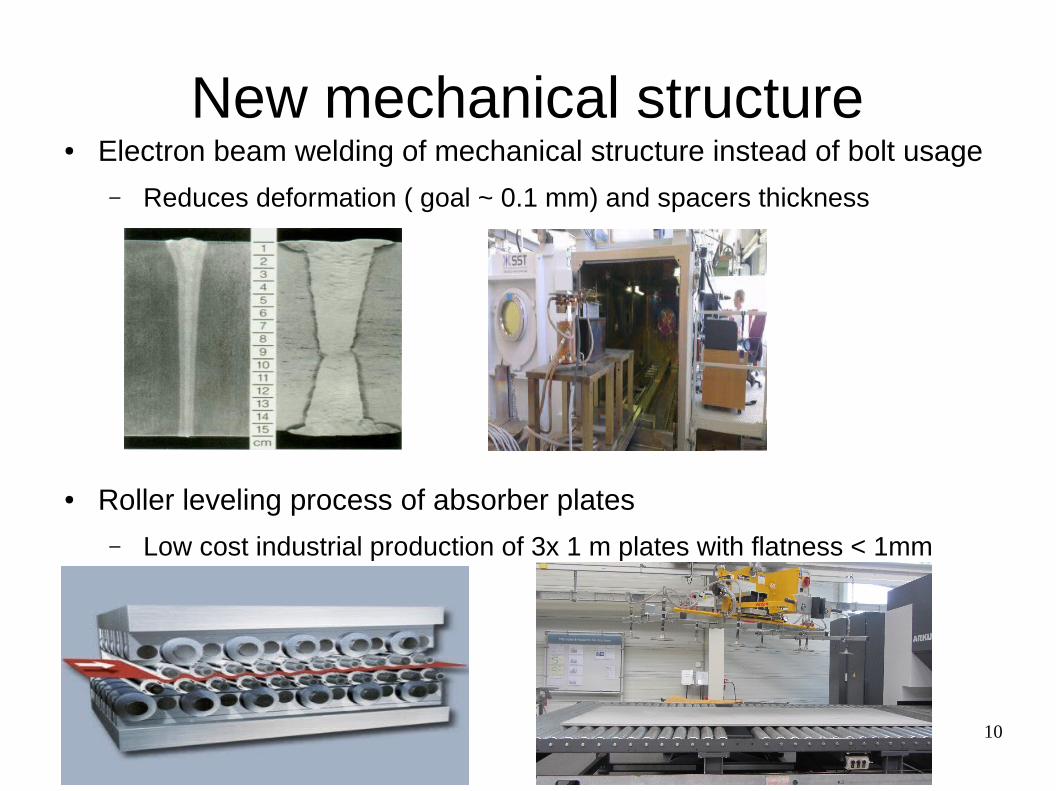
New mechanical structure● Electron beam welding of mechanical structure instead of bolt usage
– Reduces deformation ( goal ~ 0.1 mm) and spacers thickness
● Roller leveling process of absorber plates
– Low cost industrial production of 3x 1 m plates with flatness < 1mm
11
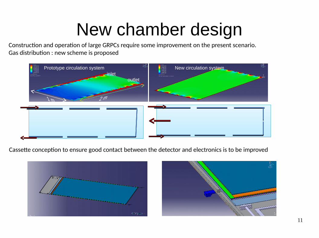
New chamber design
inletoutlet
Prototype circulation system New circulation system
Construction and operation of large GRPCs require some improvement on the present scenario.Gas distribution : new scheme is proposed
Cassette conception to ensure good contact between the detector and electronics is to be improved
12
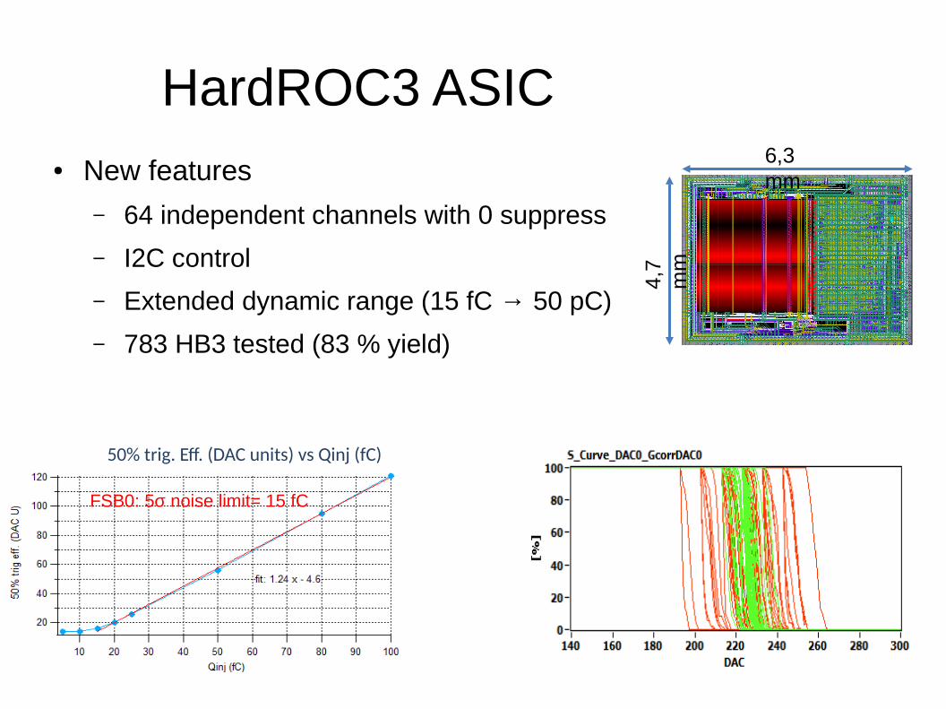
HardROC3 ASIC● New features
– 64 independent channels with 0 suppress
– I2C control
– Extended dynamic range (15 fC → 50 pC)
– 783 HB3 tested (83 % yield)
6,3 mm
4,7
mm
FSB0: 5σ noise limit= 15 fC
50% trig. Eff. (DAC units) vs Qinj (fC)
13
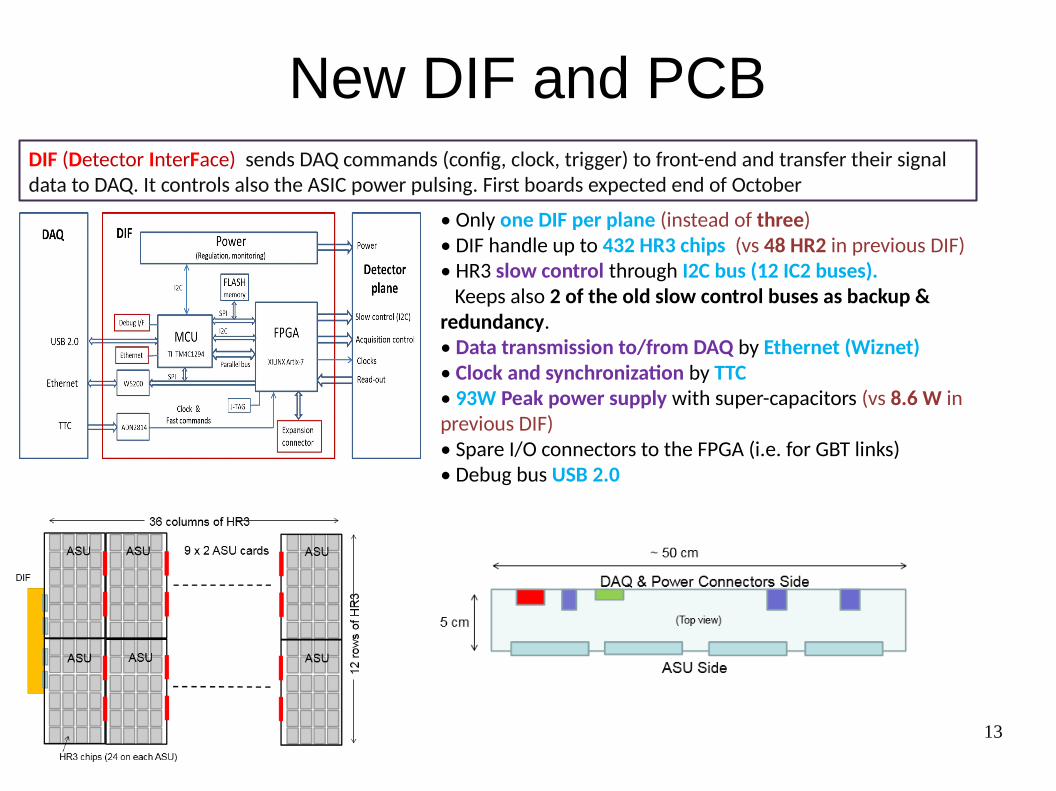
New DIF and PCB
• Only one DIF per plane (instead of three)• DIF handle up to 432 HR3 chips (vs 48 HR2 in previous DIF)• HR3 slow control through I2C bus (12 IC2 buses). Keeps also 2 of the old slow control buses as backup & redundancy.• Data transmission to/from DAQ by Ethernet (Wiznet)• Clock and synchronization by TTC • 93W Peak power supply with super-capacitors (vs 8.6 W in previous DIF)• Spare I/O connectors to the FPGA (i.e. for GBT links)• Debug bus USB 2.0
DIF (Detector InterFace) sends DAQ commands (config, clock, trigger) to front-end and transfer their signal data to DAQ. It controls also the ASIC power pulsing. First boards expected end of October
14
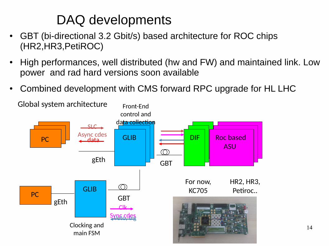
DAQ developments● GBT (bi-directional 3.2 Gbit/s) based architecture for ROC chips
(HR2,HR3,PetiROC)
● High performances, well distributed (hw and FW) and maintained link. Low power and rad hard versions soon available
● Combined development with CMS forward RPC upgrade for HL LHC
Global system architecture
HR2, HR3, Petiroc..
For now, KC705
GBT
GLIB
Front-End control and
data collection
Clocking and main FSM
PC
gEth
gEth GBT
PC GLIB DIF Roc based ASU
ClkSync cdes
SLCAsync cdes
Veto, trg
data
15
Conclusions
● The GRPC-SDHCAL 1 m3 prototype was built according ILD constraints– One-side services, ~ no cooling, minimized size
● It was tested during several beam tests on cern facilities with hadron and electron beam and achieved very good performances both in term of RPCs efficiencies and noise and in energy reconstruction and resolution. The high granularity is used for PFA and particle id. The 3 thresholds electronic allows a refined treatment of high energy showers or electrons.
● The next step is a technological prototype of large (3x1 m2 planes) ILD HCAL module. It will include updated versions of nearly all components (mechanic,chambers, ASICs, Front end and DAQ). Construction and performances tests are expected for end of 2017.