Teldronix - docmesure.free.frdocmesure.free.fr/manuels/Tektronix/Serie 7000/plugins...
26
T eld ronix COMMITTED TO EXCELLENCE Digitpl Accuracy Analog Interpretation 7000 Series Digital Plug-in Applications time and frequency digital delay amplitude temperature .. .more than an oscilloscope
-
Upload
hoanghuong -
Category
Documents
-
view
215 -
download
0
Transcript of Teldronix - docmesure.free.frdocmesure.free.fr/manuels/Tektronix/Serie 7000/plugins...
TeldronixCOMMITTED TO EXCELLENCE
Digitpl Accuracy
Analog Interpretation
7000 SeriesDigital Plug-inApplications
time and frequencydigital delayamplitude
temperature
. ..morethan an oscilloscope
TABLE OF CONTENTS
I ntrod uction
. . . . . . . . . . . . Page
31Α. Timing and Freq uency ;
Introduction to 7D14Digital Counter and7D15 Universal Counter/Timer Plug-ins
. . . . . Pages
4-71Β. Timing Measurements
with the 7D15
. . . . . . Pages . 8-121 C . Frequency Measurements
with the 7D14 and7D15 . . . . . . . . . . . . . . Pages 12-13
2Α. Digital Delay; Intro-duction to the 7D10and 7D11 DigitalDelay Units . . . . . . . . Pages 14-15
213. Delay-by-TimeM easurements withthe 7D11
. . . . . . . . . . Pages 15-182C. Delay-by-Events
with the 7D10 and7D11 . . . . . . . . . . . . . . Page 18
3Α . Amp litude andVoltage ; Introductionto the 7D12 Α/DConverter and 7D13Digital Multimeter withModules-Ml, M ulti-function Module, Μ2,Sam ple/ Hold M oduleand Μ3, VoltsModule
. . . . . . . . . . . Page
183Β . Sam ple and Hold and
True RMS Meas ure-ments with the 7D12/Μ2and 7D12/M3
. . . . . . Pages 19-204.
Temperature Measure-ments with the 7D12/M2an d 7D13 . . . . . . . . . . Page 21
Digital Ap plication Notes,Ordering Information an dBusiness Rep ly Card
. . . . Pages 22-23
The purpose of this booklet . . .
. . . is to familiarize you with the Tek-
The oscilloscope is α po p ular, timetronix 7000 Series d igital plug-in units,
proven electronic measurement tool . Itsand to show you how they can make
bandwid th, sensitivity, and the interpre-your oscilloscope α more versatile, ac-
tiυe power in herent in its visual d isplaycurate and easy to use measurement
make it an unparalleled device for ac-tool . The booklet is divided- into four
q uiring an d displaying electronic sig-sectio ns : Timin g and Frequency Mea-
nals. Yet with its many irreplaceablesuremen ts, Digital Delay Measure-
qualities, theoscilloscope typically can-ments, Am p lit u d e and Voltage
not compare with α d igital instrumentMeasurements,
andTemperature
such as α DVM or α d igital counter forMeasurements, with α helpful cross-
accuracy or resolution .in dex of applications and d igital plug-
The plug-in compartments in the Tek-in units.
tronix 7000 Series mainframes and theEach section p rovides α brief descri p-
availability of crt readout, offer α εοη-tion of the featu res and operation of the
venient method of add i n g true d igitalrelated plug-ins, and some applications
measurement capability to your oscillo-to help illustrate the full measurement
scope. The Tektronix 7000 Series offerspossibilities that these plug-ins offer.
α full complement of digital measure-
This booklet will be updated period ical-
ment plug-ins. The units include α εουη -
ly with new applications and other in-
ter, universal counter/timer, two d igitalformation to hel p you makefuller use of
delays, multimeter, samp le and hold
your digital plug-ins.
DVM, and RMS voltmeter.
Includ ing one or more digital plug-insi n your 7000 Series oscillosco pe systemprovides you with the added accuracyand resolution of α d igital instrumeIt also opens the door to α numberWmeasurements that cannot be madewith either an oscillosco pe or α d igitalmeasurement instrument alone.
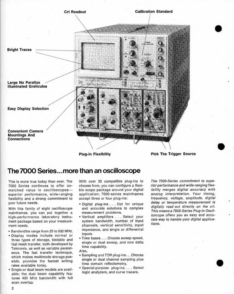
Bright Traces
Large No ParallaxIlluminated Graticules
Easy Display Selection
Convenient CameraMountings AndConnections
2
tu nes 400 MHz ban dwid th with fullscan overlap .
Crt Readout
Calibration Standard
Plug-in Flexibility
Pick The Trigger Source
The 7000 Series . . . more than an oscilloscopeTh is is more true tod ay than ever . The
With over 35 com p atible plug-ins to
The 7000-Se ries commitment to supe-
7000 Series continues to offer υη -
choose from, you can configure α flexi-
rior performance and wide-ranging flex-
m atch e d value i n oscillosco pes-
ble scope package arou nd your digital
ib ί lίty merges digital accuracy withs up erior performance, wi d e-ran ging
app lication ; 7000-series mai nframes
analog interpretation . Your timing,flexibility and α strong commitment to
accept three or four plug-ins:
frequency, voltage, amplitude, digitalyour future nee ds.
" Digital p lug-i ns . . . Op t for unique
delay or temperature measurement is
With this family of eight oscillosco pe
and accurate solutions to complex
digitally read out directly on the crt .
mainframes, you can put together α
measurement problems.
This means α 7000-Series Plug-in Oscil-
hig h-performance lab oratory instru-
" Vertical amp lifiers . . . Select your
loscope offers you an easy and accu-
ment pac kage based on your meas u re-
system bandwid th, number of input
rate way to handle your digital αρρ1ίεα -
ment needs.
channels, vertical sensitivity, i nput
tίons .
" Ban dwid ths range from 25 to 500 MHz.
impedance, an d single or differential
*Display modes incl ude normal or
inputs.
three types of storage, bistable and
" Time bases . . . Choose sweep speed,
fast mesh transfer, both developed by
si ngle or dual sweep , and now delta
ί
Te ktronix, as well as variable persist- time cap ability .
Ι
ence . The fast tran sfer tech nique, Also,
which makes multimode storage pos-
" Sam pling and TDR plug-ins . . . Choose
sible, p rovides the fastest writing
single or du al channel samp li ng plusrates available tod ay .
time domain reflectometry .
" Single o ravailable
beam models are avail-
" Special-purpose p lug-ins . . . Selectdualable ; th e dual beam capability tea-
logic analyzers, and cu rve tracers.
Time and Frequency. With our universalcounter/timer γου can visually selectcounter start and stop points on your
Tektronix has long recognized the con-
'
waveform to measure p ulse period ,
venience and ease of operation af-
pulse width, or more complex parame-
forded by crt readout of scale factors,
ters li ke risetime, the time betwee n non-
test dates, test numbers, and other per-
adjacentad j acent events, or the freq uency of α
tinent test data . The d igital plug-insgated burst. Two examples of visually
give you the further convenience of the
selected meas u rements t h at you can
speed , repeatability, and p recision of
make are the time between the first and
d igital measurements, with the mea-
eighth pulse in α data trai n or th e width
surement res u lts displayed on the crt.
of α pulse that occurs in the midd le of
Individual d igital plug-ins provide other
α control sequence . Both our counters
time saving features . Th e universal
p rovide gate d is plays of their measure-
counter/timer, for examp le, offers fin-
ment intervals, which can be d isp layedgerti p selection of frequency, p ulse
on the crt to reduce errors in trigger
period , p ulse wid th and time interval
level adjustments, and make it easier
measurements . Visual d isp lay of the
for you to see exactly what measure-
gate waveforms lets you set up mea-
me nt you are making. You can also
surements quickly and precisely .
make single-s h ot measuremen ts withboth counters . You mig h t, for exam p le,
more accuracymeasure th e wi dth of α noise sp i ke in αcontrol sequence to determine th eamount of filtering needed in α circuit .
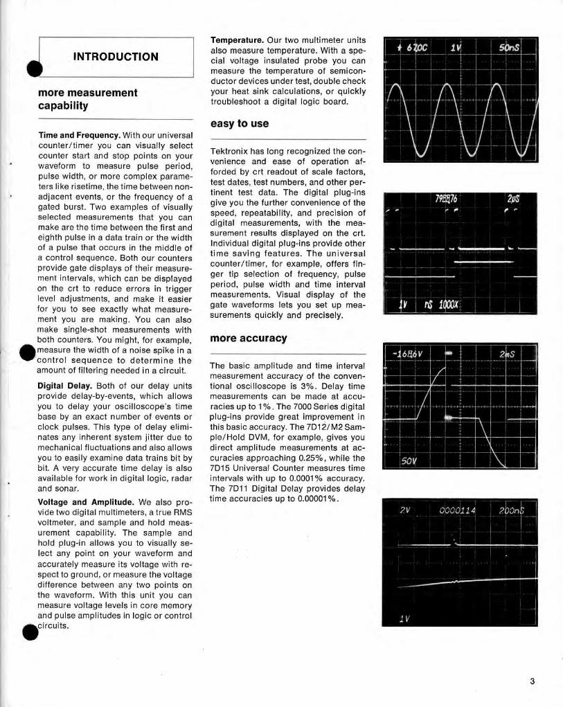
The basic amp litude and time intervalmeasurement accuracy of the conven-
`
Temperature. Ou r two multimeter units
I NTRODUCTION
also measure temperature. With α spe-cial voltage insulated probe you canmeasure the temperature of semicon-ductor devices under test, double check
more measurement
your heat sink calculations, or quicklycapability
troubleshoot α d igital logic board .
vid e two d igital multimeters, α true RM Svoltmeter, and samp le and hold meas-u rement capability . The sample an dhold plug-in allows you to visually se-lect any poi nt on you r waveform an daccurately measure its voltage with re-s pect to groun d , or measure the voltagedifference between any two points onthe waveform . With th is unit you canmeasure voltage levels in core memoryand pulse am p litudes in logic or control
icircuits.
easy to use
Digital Delay. Both of our delay units
tional oscilloscope is 3°/ο . Delay timep rovi de d elay-by-events, which allows
measurements can be mad e at accu-you to delay your oscilloscope's time
racies up to 1 % . The 7000 Series digitalbase by an exact number of events or
p l ug-ins p rovi de great imp rovement i nclock pulses . T h is type of delay elimi-
this basic accuracy . The 7D12/M2 Sam-nates any inheren t system jitter due to
p le/Hol d DVM, for exam p le, gives youmechanical fluctuations and also allows
direct amp litude measurements at ac-you to easily exami ne data trains bit by
curacies app roaching 0.25%, wh ile theb it . Α very accurate time d elay is also
7D15 Universal Counter measures timeavailable for work in d igital logic, radar
i ntervals with up to 0.0001 °/ο accuracy .and sonar.
The 7D11 Digital Delay p rovides delayVoltage and Am plitude. We also pro-
time accuracies up to 0.00001% .
1Α TIM ING ANDFREQUENCY
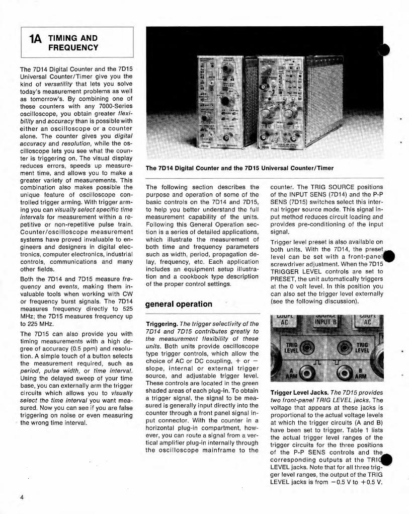
The 7D14 Digital Counter and the 7D15Universal Counter/Timer give you thek ind of versatility that lets you solvetod ay's measurement p roblems as wellas tomorrow's . By combin ing one ofthese co unters with any 7000-Seriesoscilloscope, you obtain greater flexi-bility and accuracy than is possible witheit her an oscillosco p e or α co unteralone. The counter gives you digitalaccu racy and resolution, wh ile the os-cillosco pe lets you see what the cou n -ter is triggeri ng on . The visual d isplayreduces errors, speed s up measure-
The 7D14 Digital Counter and the 7D15 Universal Counter/Timerment time, and allows you to make αgreater variety of meas urements. Thiscombination also makes possible the
The following section describes the
counter. The TRIG SOURCE positionsu niq ue feature of oscillosco pe con-
purpose and operation of some of the
of the INPUT SEN S (7D14) an d the Ρ-Ρtrolled trigger arming. W it h trigger arm-
basic controls on the 7D14 and 7D15,
SENS (7D15) switch es select this inter-ing you can visually select specific time
to h el p you better u n derstand the full
παΙ trigger source mode. This signal in-intervals for measurement with in α re-
measurement cap ability of the units.
put method red uces circuit loading andpetitive or non-repetitive pulse trai n.
Following this General Operation sec-
provides pre-conditioni ng of the inputCounter/oscilloscope measurement
tion is α series of detailed applications,
signal .systems have p roved invaluable to en-
whichillustrate the measurement of
Trigger level preset is also available ongineers and d esigners in d igital elec-
both time an d frequency parameters
both units. With the 7D14, the presettronics, computer electronics, industrial
such as wid th, period , propagation de-
level can be set wit h α front-panel,controls,
communications
andmany
lay, frequency, etc . Each app lication
screwd river adjustment . When the 7D15other fields.
i ncl ud es an equi pment setu p illustra-
TRIGGER LEVEL controls are set toBoth the 7D14 and 7D15 measure fre-
tion and α cookbook type descriptionPRESET,the unit automatically triggersquency and even ts, makin g them i n-
of the p roper control settings .
at th e 0 volt level. In th is position youvaluable tools wh en working with CW
can also set the trigger level externallyor frequen cy burst signals. Th e 7D14
eneral et eration
(see the following discussion) .g pmeasures frequency directly to 525MHz; the 7D15 measures freq uency upto 225 MHz.
Triggering . The trigger selectivity of the
The 7D15 can also provide you with
7D14 and 7D15 contributes greatly to
timing measurements with α high de-
the measurement flexibility of these
gree of accuracy (0 .5 ppm) an d resolu-
units. Both units provi de oscillosco pe
tion . Α simp le touch of α button selects
type trigger controls, wh ich allow the
the measurement req uired, suc h as
choice of AC or DC cou pling, + or -
period, pulse width , or time inte rval.
slope, i nter n al or extern al trigger
Using the d elayed swee p of your time
source, an d ad j ustable trigger level.
base, you can externally arm the trigger
These controls are located in the green
circuits which allows you to visually
shaded areas of each plug-in . Το obtain
Trigger Level Jacks. The 7D15 providesselect the time interval you want mea-
α trigger signal, the signal to be mea-
two front-panel TRIG LEVEL jacks. T hesured. Now you can see if you are false
sured is generally in put d irectly into the
voltage that appears at these j acks istriggering on noise or even measuring
counter th rough α front panel signal in-
proportional to th e actual voltage levelst he wrong time inte rval.
p ut connector. With the counter in α
at which the trigger circuits (Α and Β)horizontal plug-in compartment, how-
have been set to trigger. Table 1 listsever, you can ro ute α sig nal from α ver-
the actual trigger level ranges of thetical am p lifier plug-in internally throug htriggercircuits for the three positio nsth e oscillosco p e mainframe to t h e
of the Ρ-Ρ SENS co ntrols and th ecorrespon d ing outp u ts at th e TRIOLEVEL jacks. Note that for all th ree trig-ger level ranges, th e output of the TRIGLEVEL jacks is from -0 .5 V to +0.5 V.
For t h e 5 V and 50 V ranges, the TRIG
counter to make highly accurate mea-
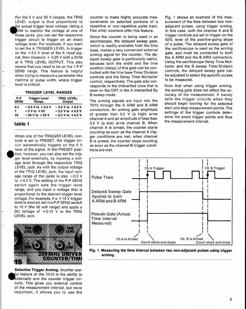
Fig . 1 shows an exam ple of the mea-LEVEL output is thus pro portional to
surements on selected portions of α
surement of the time between two non-he actual trigger level voltage. Usi ng α
repetitive or non-repetitive pulse train.
adj acent pulses, using trigger arming .VM to monitor the voltage at one of
Few other counters offer th is feature .
In th is case, both the channel Α and Βth ese jacks, you can set the respective
Since the counter is being used in an
trigger controls are set to trigger on thetrigger circuit to trigger on an exact
oscilloscope, the delayed sweep gate,
50% level of the positive-going slopevoltage level . For examp le, if you want
which is readily available from the time
of α pulse . The delayed sweep gate ofto set the Α TRIGGER LEVEL to trigger
base, ma kes α very convenient external
the oscilloscope is used as the armin gon th e +2.5 V level of the Α i nput sig-
armi ng signal for the counter . The de-
gate, and must be connected to bothηαΙ, then measure + 0.25 V with α DVM
layed swee p gate is particularly useful,
the Α ARM and the Β ARM connectors .at Α TRIG LEVEL OUTPUT. This also
because both the wid th and the time
Using theoscilloscope Delay Time ΜυΙ-means that you need to be on the 1 Ρ-Ρ
position (delay) of th is gate can be con-
tiplier and the Β swee p Time/Divisio nSENS
range . This feature is helpful
trolled with thetime base Time/ Division
controls, th e delayed swee p gate canwhen trying to measure α parameter like
controls an d the Delay Time M ulti plier
beadj usted to select the specific pulsesrisetime or pulse width, where trigger
control, respectively. The gate also cor-
to be measured.level is critical,
responds to the intensified zone that is
Note th at when using trigger arming,
Ρ-Ρ
Trigge r Level
TRIG LEVELThe arming signals are input i nto the
tells t he trigger circuits when t hey
7D15 th rough the Α A RM and Β ARM should begin looki ng for the selected0.1
-0.5 ν to + 0.5 ν
-0.5 ν to +0.5 ν start and stop measurement points.-5 ν to +5ν
-0.5V to +0.5V
connectors. An arming gate amp litude . The
10
-5ο ν tο +50V
- ο.5 ν to +ο.5 ν
of greater than 0.5 V (α high) arms
settings of the trigger controls deter-ch annel Α and an am plitude of less thanminethe exact trigger points and thus0.2 V (α low) arms channel Β . When
the measurement interval .
SENS Range Output
table 1
TRIGGER LEVEL RANGES
seen on the CRT in the Α Intensified By
the arming gate does not affect the ac-Β sweep mode .
curacy of the measurement. It merely
chan nel Α is armed, the counter starts- -
---
counting as soon as the channel Α trigWh en on e of the TRIGGER LEVEL con-
ger con ditions are met; when c hanneltrols is set to PRESET, the trigger cir-
Β is armed, the counter stops cou ntingcu it automatically triggers on the 0 V
as soon as the channel Β trigger con d i-
10level of t he signal . In the PRESET posi-
tions are met.tion, however, you can also set the trig-ger level extern ally, by i nputin g α volt-
Ι
Ιage level throug h the respective TRIG
Ι
Ι
ΙLEVEL jack. As with the output voltage
Ch Α Trigger
Ι Ch Β Trigge rof the TRIG LEVEL j ack, the i nput volt-
Ί
FILage range of the jacks is also -0 .5 V
Pulse Trainto +0.5 V. T he setting of th e Ρ-Ρ SENS
Ι
ΙF1
switc h agai n sets th e trigger levelrange, an d you input α voltage that is
Ι
Ι
Ι
Ιproportio nal to the desired trigger level
Delayed Sweep Gate
voltage. For exam ple, if α +15 Vtrigger
Applied to both
Ι
level is desired, set th e Ρ-Ρ SENS switch
ΑARM and ΒARM
Ι
Ιto 10 V (the 50 volt ran ge) and apply α
Ι
Ι
ΙDC voltage of +0.15 V to the TRIGLEVEL jac k.
Pseudo Gate (Actual
Ι
Ι
ΙTime Interval
Ι
ΙMeasu red)
Ιj.TRIG
Ι Ι
Ι ΙLEVEL ,¬ ~
Ι
ι
ι
ι
ΒARM
Selective Trigger Arming. Another use-ΜυΙ feature of the 7D15 is the ability tom
xternally arm the counte r trigger circuits . Th is gives you external controlof the measurement interval, but moreim portant, it allows you to use th e
ChΑ is Armed
Ch B is ArmedCount starts and slope
Count stops and slope
Fig . 1 Measuring the time interval between two non-adjacent pu lses using trigger225MHz UNIVERarming.G0UΝΤΕR/ΤΙΜ1
_
-___,
5
: .
r
. i . . .-. . .
. .
.. . ι
.
the signal being measured, you have, ., , _ _ _,
. . -
non-repetitivenals, like gated bursts . As with time
interval measurements, the delayed.display .
-sweepgate
.
- oscilloscope . .Intensified
.
.
.-
.nvenient gating signal .cates position of arming gate .
is generated each time the trigger an darming conditions are met. Α th ird dis-play, CH Β , is α conditio n ed signal that6
is derived from the 7D15's CH Β triggercircuit . It is useful for setting up thetrigger conditions of chan nel Β .
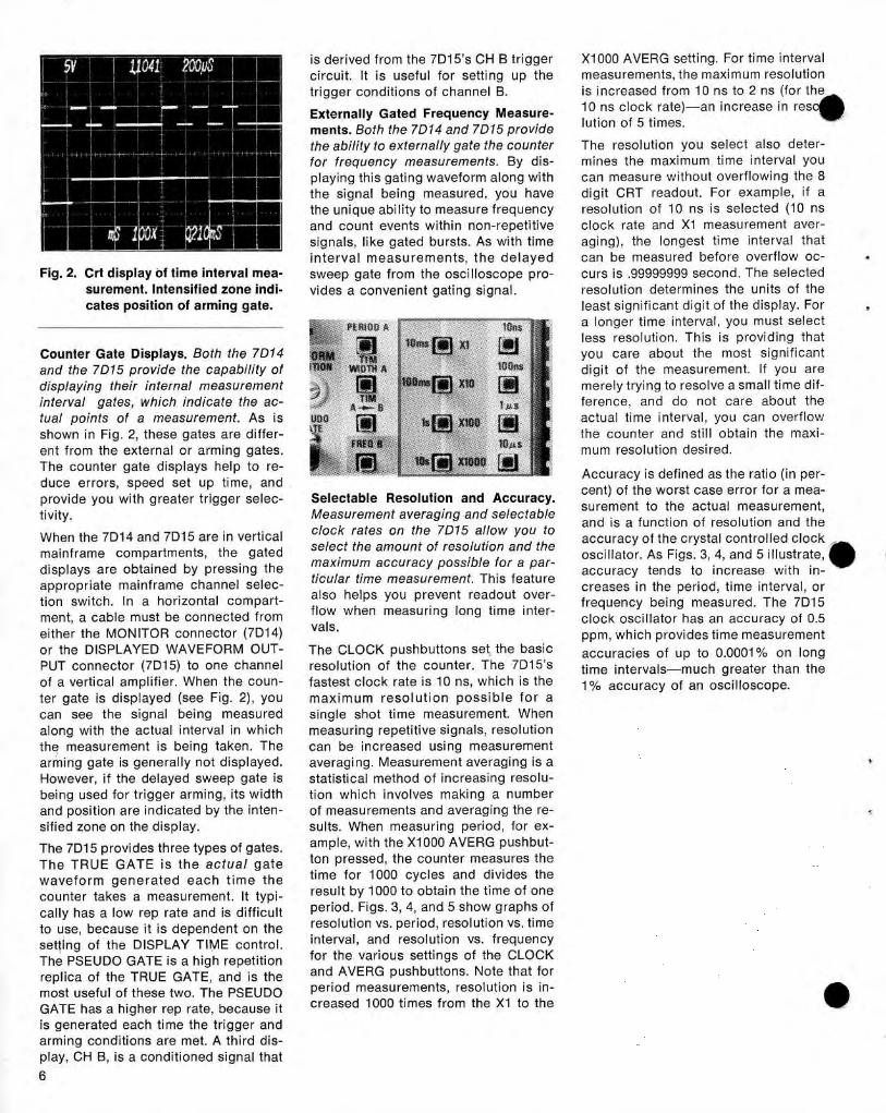
Counter Gate Displays . Both the 7D14and the 7D15 provide the capability ofdisplaying their internal measurementinterva l gates, which indicate the ac-tual points of α measurement. As isshown in Fig . 2, these gates are d iffer-ent from the external or arming gates.The counter gate d isplays h el p to re-duce errors, s peed set up time, andprovide you with greater trigger selec-
Selectable Resolution and Accuracy .tivity .
Measurement averaging and selectable
When the 7D14 an d 7D15 are in vertical
clock rates on the 7D15 allow you to
mainframe compartments,
t he
gated
select the amount of resolution and the
d isp lays are obtained by p ressing the
maximum accuracy possible for α par-
app ro priate mainframe c hannel selec-
ticular time measurement. This featu re
tion switch. In α horizontal compart-
also helps you prevent readout over-
ment, α cable must be connected from
flow when measuring long time inter-
either the MONITOR conn ector (7D14)
vals.
or the DISPLAYED WAVEFORM OUT-
The CLOCK p us h buttons set the basicPUT connector (7D15) to one channel
resolution of the counter. The 7D15'sof α vertical am plifier. When the coun-
fastest clock rate is 10 ns, whic h is theter gate is d isp layed (see Fig . 2), you
maximum resolution possible for αcan see the signal being measuredsingleshot time measurement. Whenalong with the actual i nterval in wh ichmeasuringre petitive signals, resolutionth e measu rement is being taken . The
can be increased using measurementarming gate is generally not displayed.
averagi ng . Measurement averaging is αHowever, if the delayed sweep gate is
statistical method of increasing resolu-bei n g used for trigger arming, its widthtionwhich involves making α numberan d position are i ndicated by the inten-
of measurements and averaging the re-sified zone on the d isplay.
sults . When measuring period, for ex-
The 7D15 provides th ree types of gates.
ample, with the Χ1000 AVERG pushbut-The TRUE GATE is the actual gate
ton p resse d, the cou nter measu res the
waveform gen erated eac h time t he
time for 1000 cycles and divides the
counter takes α measurement . It typ i-
result by 1000 to obtain t h e time of one
cally h as α low rep rate and is difficult
period . Figs. 3, 4, and 5 s how graphs of
to use, because it is dependent on the
resolution vs . period, resolution vs . time
settin g of th e DISPLAY TIME control.
interval, and resolution vs . freq uency
The PSEU DO GATE is α high repetition
for the various settings of the CLOCK
rep lica of the TRUE GATE, and is the
and AVERG p ush butto n s . Note that for
most useful of these two. The PSEUDO
period measu rements, resolution is in-
GATE has α h ig h er rep rate, because it
creased 1000 times from the Χ1 to the
Χ1000 AVERG setting . For time intervalmeasurements, the maximum resolutionis increased from 10 ns to 2 ns (for the10 ns clock rate)-an increase in reso~lution of 5 times .
The resolution you select also deter-mines the maximum time interval youcan measure wit h out overflowing the 8d igit CRT readou t . For exam ple, if αresolution of 10 ns is selected (10 nsclock rate and Χ 1 measurement aver-aging), the longest time interval thatcan be measured before overflow oc-curs is .99999999 second . The selectedresolution determines the u nits of theleast sign ificant digit of the d isplay . Forα longer time interval, you mu st selectless resolution . T his is p roviding thatyou care about the most significantd igit of the measu rement . If you aremerely trying to resolve α small time dif-feren ce, and do not care about theactual time interval, you can overflowt h e counter and still obtain the maxi-mum resolution desired.
Accuracy is defined as the ratio (in per-cent) of the worst case error for α mea-su rement to the actual measurement,an d is α fun ction of resol ution and theaccuracy of the crystal controlled clockoscillator . As Figs. 3, 4, an d 5 illustrate,*
Ιaccuracy tends to i ncrease with in-creases in the period, time interval, orfrequency being measured . T h e 7D15cloc k oscillator h as an accuracy of 0.5ppm, whic h p rovi des time measurementaccuracies of up to 0.0001% on longtime intervals-much greater than the1% accuracy of an oscillosco pe.
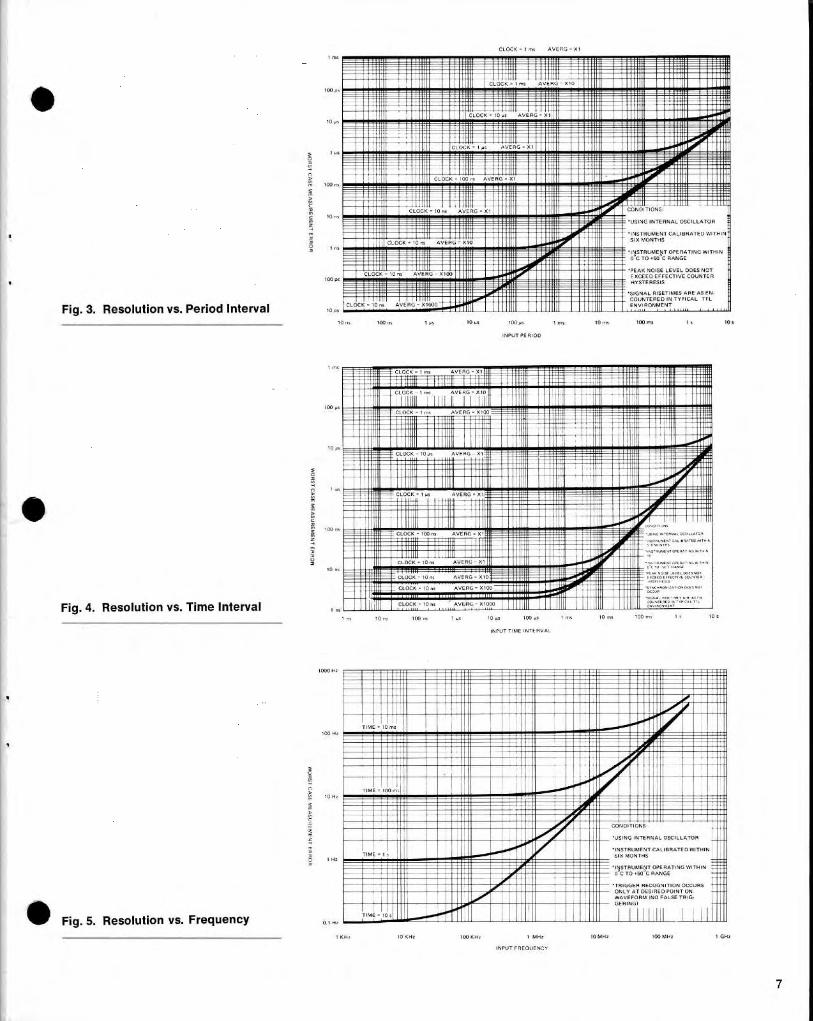
Fig . 3 . Resolution vs . Period Interval
Fig . 4 . Resolution vs . Time Interval
Fig . 5 . Resolution vs . Frequency
CLOCK - ιπα
AV- = χι
1Q"υl ιιι
ι/ ι~mrιιΙσσιηιι
ωσιιιι~Ν~ΙΙΙιιι "ωιιισσι r ιιιΝθ1"ΙΝΙ"ΙΝ~Ν"~~~"ii"ΝΙΝΙΙΙΙ~ΝΙΙΙΙΙΙΙ"Ν" ΙΝΙΙ~~:;~, ιπ
~~"ρ11 ΊΊ
ι mv~i ι~W:: :iιi ~ιιιιιiω::::ίιίS:Sί: ιίιιιiι~ _ ~Ιιιi"iΙΑ
"ΙίΙΙι~ιιω lιιιι~ ΥΙ"ιι=σr ιιιι
η 1 Ι; ;ίθ~/" Ι111Ί11
ι lιωιιΙιΙιlιιιlιιϋίίiιι"~., ι ~
ΙΙι "//ΙΙΙΙσ~ " /υ 111σ. ". ΙΛΊ~"Ληlηιi'__ ι""ΙΊΊΛσ~" Λη11 Λ~~i111i~H1111 / ΙΙωΙ1ι/ΝΙ""Ι~!:;,ιθΙ~ι/11 ΙΙΙΙΙ//1111Ι 1
"%Νι~'~Ιιυ1
. ιι
~~ ίΙ1{{"~~ΝΙΙΙ/iiilrιr ι ιι
ιη
ilιι~ό~;ING INTERNAL OSCILLATOR
ί:"""~"WΎΙΙθ~~1Ι ~ΝΙΙΙΙΙ~~ "/ /1 Ι/σ lΙΙιΙι!~ιΙ
11
_
Ιι~i:_ sαs
SIX MONTHS
~~~"YIIIi_r "" 1ΙΙ ω""""ΙΧ
ιJ
1
i--'
IL",
ι 0ο ,*
, ω
ιοχ~α
ιοα ",m α
,0 ιητ
ι 00 ms
ια
ι0 α
INPUT PE πιοο
Wσrιr'
"
.
ιιι~sέe :°
-___'°Φ~3:". -
σΙιιem=
"~ι,Ίι~~=;ΙιίίΙiίίίίρ'mi~ ι "έ ;ί"ΊΙΙΘιΙΙ~ΙΙίΙ..~ ΙlΙ!~ίΙθίΙΙΙΙί"~ ίΙρ ?ι!lιιιΙθΙ
Ι
ΊΊ
Ι III_
σ."ιηιιιΤ"i:: ιιιιί ΙΙΙιιι
υ" ωι i~I11 ":: ιι σ" ιιωαιιισσιιιιιι
ιιιιιι Ιίί{ίΙΙΙ7
"χω
.ι
.ι~ ίφιΙι
ι""Ιιιιιι~υ" Ιιιιι~"ιιιιιιι
~~ : ιιι~~ι~~ υ~11ΙΙιιιι~_Νιωιιωιιιιιιιιιιιιιι"ΙΙΙίιιωΜιιι
ιιι
ΙΙ θθθ~~1 ~~_ _ι !__+
.:Ι
"""~ ισ~__" ιl ιω"~""Ι" ιΙ ΙυιΙι
: ιιχ~ΙΙΙΡΙ
ΙηΙιιισιωlΙιιισιυιηιισσΙιιi/Ιι lίιίι
συιιιιι ra/~πιιιιΙ :ι
Ι
slim
~ΝΊΊΪ~
ΊΊΊΙΊ
1
1i ~1ι:
~
ιιιι"
ΙΙ{ Φ
υι1
~ " "Ιιιι ~
-
CLOCK =1~ τ
AVERS - XI
Ι~
Ι- Lλ λ ' .1 ϋm
,1ΙΙ Ι
ϊ Ι Ι
ΙΙΙ
Ι
~
Ι
~'::ϊίί~σπlιιι~σ '"~sS ιιιιΙ --~"μι'~rW:Ισ ~ y~= ~~~ιιισσηιιιιισσίίιι liσσηιιιιιs/11 "σσ~Ιύύ~1' . " υηΛ
il Ιίιιι~~lιιιιι
Ι :ια lυιυ~"υίWι~ιιι~ ~ριι~iι l:υιιι Ιιιιι
ιιιΙtιιιιιιΙ"ιιιιιιι~,, Ι ~ ;~ηη~ ρΙ
ω " ί 1 ;1ιΙΙΙ=!
' ιτ~' -ON!-11ΙΝΙΙ!//ι_ ~' υΙΙΧ
mωχιιιmσm "ιι-~~~,
Ιυ
:1 Ι Ιi1Ιa ιΙm ΙΙΙΙιισυιιιΙ"" Ι Ι
lc ,α
ιοο ,σ
INPUT TIME INTERVII
ιο mα , αα m, ,, ιοτ
~~"i%ΙΊϋί~ Ι%0Ό$ilιiiί~ ιι~σ
ι σΥrι~σπΛΙl ιι~σωrrι. ~~ι ~ιιι~i~Ιιίι~ιυσυι~~1/ι " αιι~σ~~υι"Νυ1"~"υΛ111~~ Ι"Ι "o0"Ι~m"υυ :ι ll~ώ/"1
"i~llili " ι1 ~ι~ιlιιrι ιιωυιι~i2ιιrι"" Ι~
"
Ι~TI .
" ~""
ισα Ητ
Ι~ηασα~-"=~ω~ι~ίί"~~ώώί"iS=~ "Ι ~ιΥ~ΙΟ~/ΝΙΙΙϋΟ®C1Ιρ-
Ι
υιιl~σιi~rl~
r""ιι~σσ1 "ηrι
~ΙΙME ίFlΪn-M~ΦΙ~1fΙ~~sυίΝάΙe~ Ι .-°.άι~~_Ι :Ι" σσ" wrιrw on
ι:1ί~®"ιιι~ιii""Λ r
Ιι-T. NI-FR RECOGNITIONNLY AT DE
S'RED POINT ON
1 ΚΗι 1αΚΗτ
1 ΦΚΗι
1 -
ΙΟΜΗ +
1001011
1GHzINPUT FREQUENCY
1Β TIMINGMEASUREMENT
pulse width
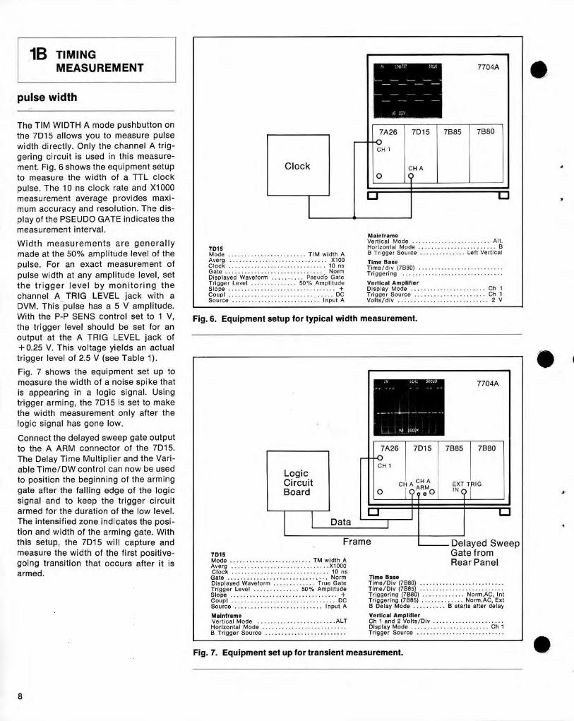
The TIM WIDTH Α mode pushbutto n onthe 7D15 allows you to measure pulsewi dth directly. Only the channel Α trig-geri ng circuit is used in this measure-ment . Fig . 6 shows the equ ipment setupto measure the width of α TTL clockpulse . The 10 ns clock rate and Χ1000measurement average p rovi des maxi-mum accuracy and resolution . The dis-play of the PSEUDO GATE ind icates themeasurement interval .
Widt h measurements are ge nerallymade at the 50%ο amplitude level of thepulse . For an exact measurement ofpulse wi dth at any amplitude level, sett he trigger level by monitoring th ec hannel Α TRIG LEVEL j ack with αDVM . This pulse has α 5 V amp litude.W it h the Ρ-Ρ SEN S control set to 1 V,the trigger level should be set for ano u tput at the Α TRIG LEVEL jac k of+0.25 V . This voltage yiel ds an actualtrigger level of 2.5 V (see Table 1) .
Fig . 7 shows t he equ i pment set up tomeasure the wi dth of α noise spi ke thatis appearing in α logic signal . Usi ngtrigger armin g, the 7D15 is set to makethe wid th measurement o n ly after thelogic signal has gone low.
Connect the delayed sweep gate outp utto the Α ARM connector of the 7D15 .The Delay Time Multiplier and the Vari-
able Time/DW control can now be usedto positio n the beginning of t h e armi nggate after the falling edge of the logicsignal and to keep the trigger circuitarmed for th e duration of the low level.The intensified zone i nd icates the posi-tion and width of the arming gate . Withth is setup, the 7D15 will capt ure andmeasure the width of the first positive-going transition that occu rs after it isarmed.
Mai nframeVe rtical M od e . . . . . . . . . . . . . . . . . . . . . . . . Alt .
711315
Ho r izo ntal M o de. . . . . . . . . . . . . . . . . . . . . .
. . ΒMode . . . . . . . . . . . . . . . . . . . . . . . . TIM wi d t h Α
8 Trigge r So ur ce . . . . . . . . . . . . . . Left Vertical
loc k . . . . . .. . . . . . . .. . . . . . . . . . . . . . . . . . . . . . .1 ρ 100
Time BaseC Time/div (7Β80) . . . . . . . . . . . . . . . . . . . . . . . . . .Gate . . . . . . . . . . . . . . . . . . . . . . . . . . . . . . . No rm
Triggering . . . . . . . . . . . . . . . . . . . . . . . . . . . . . . .Displayed Wavefo rm . . . . . . . . . . Pseudo GateT r igge r L evel . . . . . . . . . . . . . . 50% Amplitu d e
Ve rtical Ampli f ie rSlo p e . . . . . . . . . . . . . . . . . . . . . . . . . . . . . . . . . +
Display Mode . . . . . . . . . . . . . . . . . . . . . . . C h 1Co up l . . . . . . . . . . . . . . . . . . . . . . . . . ,
. DC
Tr igge r So urce . . . . . . . . . . . . . . . . . . . . . . C h 1Source . . . . . . . . . . . . . . . . . . . . . . . . . . . Input Α
Volts/div . . . . . . . . . . . . . . . . . . . . . . . . . . . . 2 V
Fig . 6. Equipment setup for typical width measurement.
7113115 Gate fromMo d e . . . . . . . . . . . . . . . . . . . . . . . . . TM width Α
RearPanelAverg . . . . . . . . . . . . . . . . . . . . . . . . . . . . . . Χ 1000Cloc k . . . . . . . . . . . . . . . . . . . . . . . . . . . . . . 10 nsGate . . . . . . . . . . . . . . . . . . . . . . . . . . . . . . . Norm
Time BaseDIsplayed Wavefo rm . . . . . . . . . . . . . True Gate
Time/Div (7880) . . . . . . . . . . . . . . . . . . . . . . . . . .T rigge r Level . . . . . . . . . . . . . . 50% Amp litude
Time/Div (7885) .Slope . . . . . . . . . . . . . . . . . . . . . . . . . . . . . . . . . +
T rigge ring (71380) . . . . . . . ..
..
. . . . . . . . . .,Α C, .1 π t
Source. . . . . . . . . . . . . . . . . . . . . . . . . . . . . . . .
DC
Triggering (71385)
. . . . . . .
.
Norm,AC, E xtou
rce
. . . . . . . . . . . . . . . . . . . . . . . . . . .
Input Α
Β Delay Mo d e
. . . . . . . . . .
Β starts afte r d elay
Mai n f r am e
Vertical Amp li f ie rVe r t ί ca Ι Mode . . . . . . . . . . . . . . . . . . . . . . . .ALT
Ch 1 and 2 Volts/Div . . . . . . . . . . . . . . . . .Ho rizo ntal Mode . . . . . . . . . . . . . . . . . . . . . . . . . .
Display M ode . . . . . . . . . . . . . . . . . . . . . . . . C h 1Β T rigge r Sou rce . . . . . . . . . . . . . . . . . . . . . . . . .
T rigge r Source . . . . . . . . . . . . . . . . . . . . . . . . . . .
Fig . 7. Equipment set up for transient measurement.
Clock
LogicCircu itBoard
2ν
12αη7Α ΙαμS ;̀
4 j~A
11
7Ή26
7D15
~
7Β85
~
7Β80
~
CH A
σ
Data `
LL Ι 41o*
6143 $QΟυβ
7704Α
7704Α
7Α26 Ι 7D15 Ι 7Β85 Ι 7880
ΟCH 1
CH Α A
ιRM
''
ΕΧΤ TR IG
Ι 4ροΟ IN?
Ι
Frame
Ι
Delayed Sweep
500m ν 'OQ06
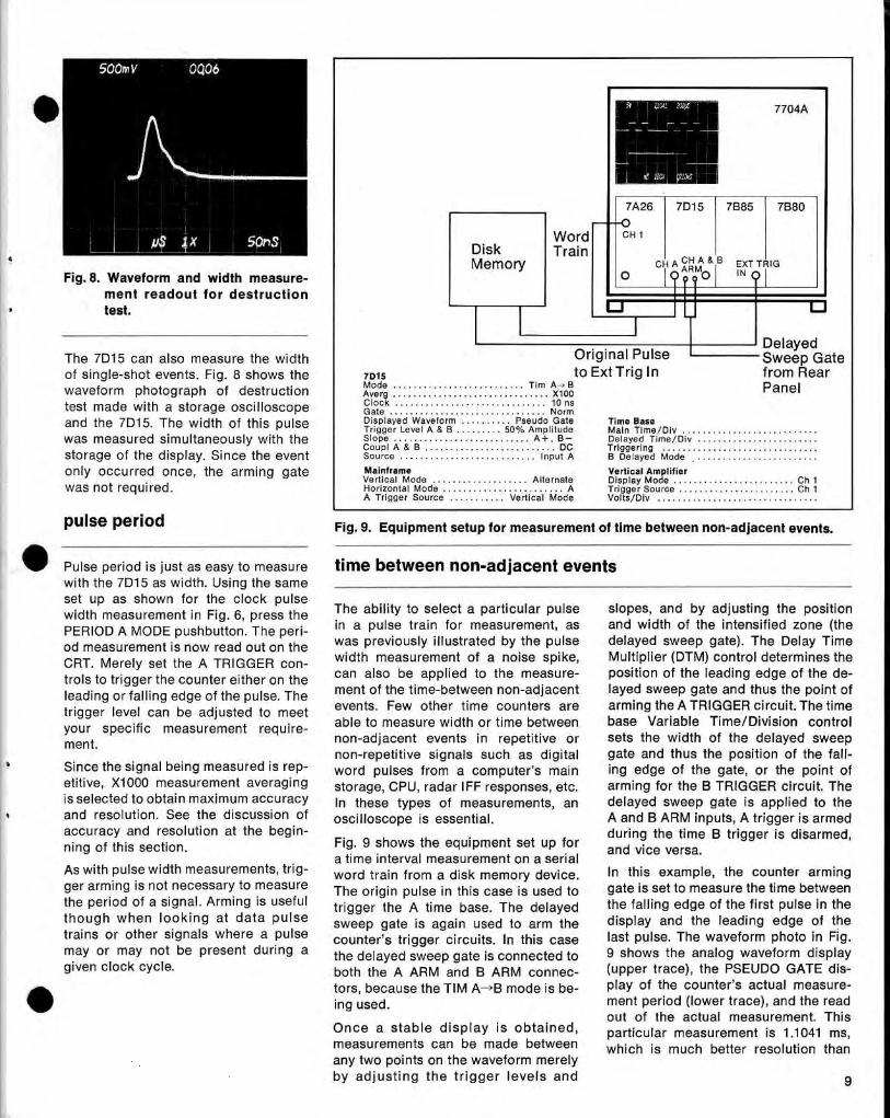
Fig. 8. Waveform and wid th measure-ment readout fo r destructiontest .
The 7D15 can also measure the wid thof single-shot events . Fig . 8 shows thewaveform photograp h of destructiontest made with α storage oscilloscopeand the 7D15 . The width of this pulsewas measured simultaneously with thestorage of the display . Since the eventonly occurred once, the arming gatewas not required .
pulse period
7D15
to Ext Trig In
from RearMode . . . . . . . . . . . . . . . . . . . . . . . . . . Tim Α-ι Β
PanelAverg . . . . . . . . . . . . . . . . . . . . . . . . . . . . . . . Χ100Clock . . . . . . . . . . . . . . . . . . . . . . . . . . . . . . 10 nsGate
.. . . . . . . . . . . . . . . . . . . . . . .
. . N ormDisplayed Waveform . . . . . . . . . . Pseudo Gate
Time BaseTr igge r Level Α & Β . . . . . . . . .50% Amp lit ud e
Main Ti me/Div . . . . . . . . . . . . . . . . . . . . . . . . . . .Slo pe . . . . . . . . . . . . . . . . . . . . . . . . . . . A+, 13-
Delayed Ti me/Div . . . . . . . . . . . . . . . . . . . . . . . .CουρΙ Α & Β . . . . . . . . . . . . . . . . . . . . . . . . . . DC
Trigge ring . . . . . . . . . . . . . . . . . . . . . . . . . . . . . . .Source . . . . . . . . . . . . . . . . . . . . . . . . . .Inp ut Α
Β Delayed Mod . . . . . . . . . . . . . . . . . . . . . . . . .
Mainfr ame
Vertical Amp lifie rV e rtical Mo d e . . . . . . . . . . . . . . . . . . . Alter nate
Disp lay Mo d e . . . . . . . . . . . . . . . . . . . . . . . . Ch 1Hor izontal Mo d e . . . . . . . . . . . . . . . . . . . . . . . . . Α
T r igger So u rce . . . . . . . . . . . . . . . . . . . . . . . Ch 1Α Trigger Sou rce . . . . . . . . . . Ve rtica Mode
Volts/Div . . . . . . . . . . . . . . . . . . . . . . . . . . . . . . . .
Fig . 9. Equipment setup for measurement of time between non-adjacent events .
Pulse period is ju st as easy to meas u re
time between non-adjacent eventswith the 7D15 as wid th. Using the sameset υρ as shown for the cloc k pulsewidth measurement in Fig . 6, press the
The ability to select α particular pulse
slopes, and by ad j usting the positionPERIOD Α MOD E push button . The ρ~r ί-
in α pulse train for measurement, as
and wi d th of the intensified zone (t h e
od meas urement is now read out on the
was p reviously illustrated by the p u lse
delayed sweep gate). The Delay Time
CRT. M erely set the Α TRIGGER con-
wid th measurement of α noise sp i ke,
Multip lier (DTM) control determines the
trols to trigger the counter either on the
can also be applied to th e measure-
positio n of the leading edge of the de-lead i n g or falling edge of the pulse . The
ment of the time-between non-adjacent
layed sweep gate and th us th e point of
trigger level can be ad j usted to meet
events . Few other time counters are
armi ng the Α TRIGGER circuit . The time
your specific
measurement require-
able to measure wi d th or time between
base Variable Time/Division control
ment .
non-adjacent events in repetitive or
sets the width of the delayed sweepnon-repetitive signals such as digital
gate and thus the position of the fall-Sin ce the signal being measured is rep-
word pulses from α computer's main
ing edge of the gate, or the point ofetitive, Χ1000 measurement averagi ng
storage, CPU, radar I FF responses, etc.
arming for the Β TRIGGER circuit . Theis selected to obtain maximum accuracy
In these types of measurements, an
delayed sweep gate is app lied to theand resol ution . See the discussion of
oscilloscope is essential.
Α and Β ARM inputs, Α trigger is armedaccuracy and resolution at the begin-
d uring the time Β trigger is disarmed ,nin9 of this section.
Fig . 9 shows the eq uipment set up for and vice versa.α time interval meas u rement on α serial
As wit h pu lse width measurements, trig-
word train from α d is k memory device .
In this exam p le, the counter armingger arming is not necessary to measure
The origin pu lse in this case is used to
gate is set to measu re the time betweenthe period of α signal . Arming is useful
trigger the Α time base
the falling edgeth o ugh when look ing at data pulse
. The delayeddisplayand gheο leading edge of the
trains or other signals where α pulse
counter's trigger circuits . In this case
last pulse . Th e waveform photo in Fig .may or may not be p resent d uring α
the d elayed sweep gate is connected to
9 shows the analog waveform d isp laygiven clock cycle.
both the Α ARM and Β ARM connec-
(upper trace), t he PSEUDO GATE dis-tors, because the TIM Α-Β mode is be-
play of the coun ter's actu al meas u reing used .
ment period (lower trace), and the readout of the actual measurement. This
Once α stable disp lay is obtain e d ,
particular measurement is 1 .1041 ms,measurements can be made betweenwhich is much better resolution thanany two points on t h e waveform merelyby ad j usting th e trigger levels and 9
Uλ.'~ 2ι1Αι
τLVΧ ; ON, ;
7704Α
7Α26 Ι 7D15 Ι 7Β85 Ι 7Β80
Word
CH 1Disk Trai nMemory
c
L.J
IY
ΑCH
θΆ & Β
ΕΧΤ TRIG
1D44 0IN ηΙ
Original Pu lse
Sweep Gateρ
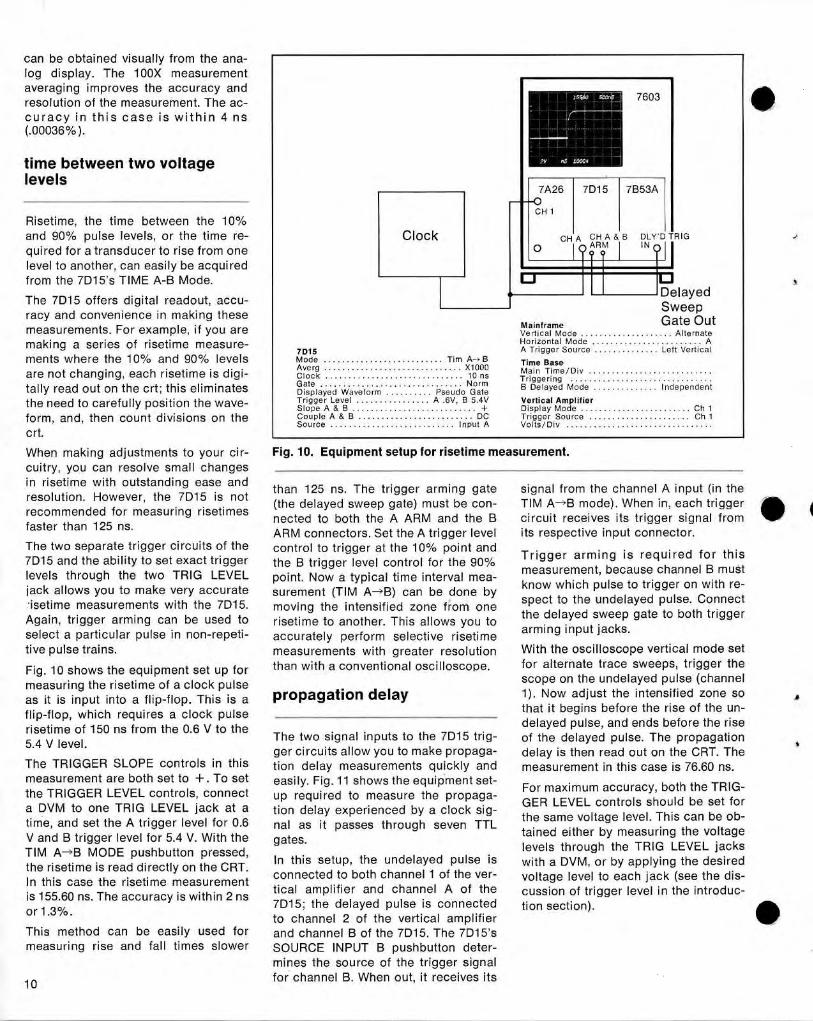
can be obtained visually from the ana-log d isplay. The 100Χ measurementaveragi ng improves the accuracy andresolution of the measurement. Th e ac-curacy in th is case is wit h in 4 ns(.00036%) .
time between two voltagelevels
Risetime, th e time between the 10%and 90% p ulse levels, or the time re-quired for α tran sducer to rise from onelevel to anot h er, can easily be acq u iredfrom the 7D15's TIME Α-Β Mode.The 7D15 offers digital reado ut, accu-racy and convenience in making t h esemeasurements . For example, if you aremaki ng α series of risetime measure-ments where the 10% and 90% levelsare not c h anging, eac h risetime is digi-tally read out on th e crt ; this eliminatest h e need to carefully position t h e wave-form, and, then count divisions on t h ecrt.
Clock
7603
0DelayedSweepGate C)"+
Mainf r a m eVertical M o d e . . . . . . . . . . . . . . . . . . . . Alte rnateHe r ί zοπtαt
Mode
. . . . . . . . . . . . . . . . . . . . . . . .
Α
713115
Α Trigge r So ur ce . . . . . . . . . . . . . . Left Ve r ticalMo d e . . . . . . . . . . . . . . . . . . . . . . . . . . Tim Α-ι Β
Time BaseAverg . . . . . . . . . . . . . . . . . . . . . . . . . . . . . . Χ1000
Main Time/Div . . . . . . . . . . . . . . . . . . . . . . . . .Clock . . . . . . . . . . . . . . . . . . . . . . . . . . . . . . 10 ns
Trigge r i ng ,
. .
Gate . . . . . . . . . . . . . . . . . . . . . . . . . . . . . . . No rm
Β Delaye d M ode
1ndependent. . . . . . . . . . . . . .Displaye d Waveform . . . . . . . . . Pse udo GateTrigger Level . . . . . . . . . . . . . . . . Α .6V, Β 5.4V
Vertical Amplifie rSlo pe Α & Β . . . . . . . . . . . . . . . . . . . . . . . . . . . +
Display Mode . . . . . . . . . . . . . . . . . . . . . . . . Ch 1Coup le Α & Β . . . . . . . . . . . . . . . . . . . . . . . . . DC
Trigger Sou rce . . . . . . . . . . . . . . . . . . . . . . C h 1Source . . . . . . . . . . . . . . . . . . . . . . . . . . . Ιπρυt Α
V olts/Div . . . . . . . . . . . . . . . . . . . . . . . . . . . . . . . .
When making adj ustments to your cir-
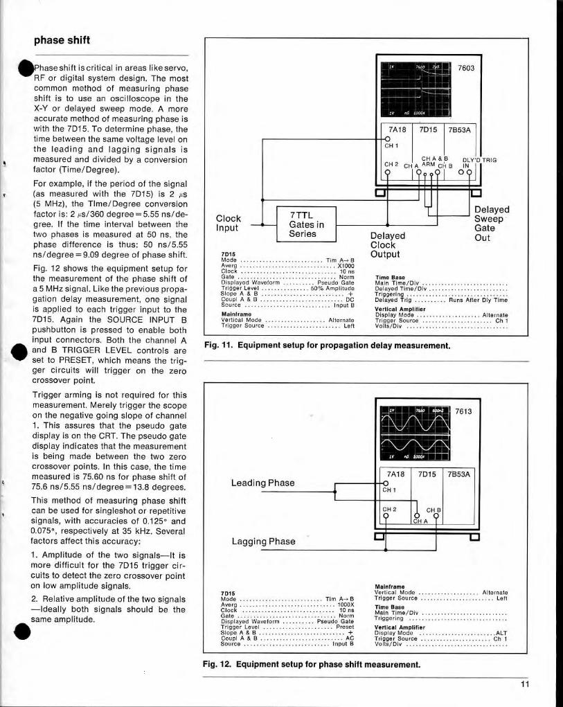
Fig . 10 . Equipment setup for risetime measurement.
cu itry, you can resolve small changesin risetime with outstandi n g ease and
than 125 ns . T he trigger arming gate
signal from t h e c h annel Α inp ut (in theresolution . However, the 7D15 is not
(the delayed sweep gate) must be con-
TIM Α-Β mode) . When in, each triggerrecommended for measuring risetimes
nected to both the Α ARM and th e Β
circuit receives its trigger
1faster than 125 ns.
gger signal fromARM connectors . Set the Α trigger level
its respective in put connector.The two separate trigger circuits of th e
control to trigger at the 10% point and7D15 and t h e ability to set exact trigger
t he Β trigger level co ntrol for the 90%
Trigger armi n g is required for th is
levels throug h the two TRIG LEVEL
point . Now α typical time interval mea-
measurement, because channel Β must
jack allows you to make very accurate
surement (TIM Α-Β) can be done by
know which pu lse to trigger on with re-
-isetime measurements with th e 7D15 .
moving the intensified zone from one
seect to the undelayed pulse . Connect
Again, trigger arming can be used to
risetime to another . This allows you to
the delayed sweep gate to both trigger
select α particular pulse i n non-repeti-
accurately perform selective risetime
arming input j acks.
tive pulse trains .
measurements with greater resol u tionWit h the oscilloscope vertical mode set
Fig . 10 s hows the eq ui pment set up for
than with α conventional oscilloscope.
for alternate trace sweeps, trigger the
measuring t h e risetime of α cloc k p ulse
scope on the undelayed pulse (ch annel
as it is input into α flip-flop . This is α
propagation delay
1) . Now adjust the intensified zone so
fΙίρ-flo p which regυί res α clock p ulse
that it begins before the rise of the υη -,risetime of 150 ns from the 0.6 V to th e
d elayed pulse, and en ds before th e rise
5.4 V level.
The two signal inputs to the 7D15 trig-
of the delayed p u lse. The propagationger circuits allow you to make p ropaga-
d elay is then read out on the CRT. TheThe TRIGGER SLOPE controls i n this
tion delay measurements quickly andmeasurement in this case is 76.60 ns .measurement are both set to + . To set
easily. Fig . 11 shows the equi p ment set-the TRIGGER LEVEL controls, connect
up required to measure the p ropaga-
FoGERr
LEVEL
accuracy, both the et for
α DVM to one TRIG LEVEL jack at α
tion delay experienced by α cloc k sig-
the
LEVEL controls should be s
time, and set the Α trigger level for 0.6
ηαΙ as it passes through seven TTLsamevoltage level . ring can be ob-
V an d Β trigger level for 5.4 V . W it h th e
gates.
tained either by measuring the voltage
TIM Α~Β MOD E p ushbutton pressed ,
levels throug h th e TRIG LEVEL jacks
t he r ί et ίme is read directly on the CRT.
In this setup, the undelayed pulse is
with α DVM, or by app lying the desired1η this case the αί diec measurement
connected to both channel 1 of the ver-
voltage level to each j ac k (see the d is-
is 155.60 ns . The accuracy is within 2 ns
tical amplifier and chann el Α of the
cussion of trigger level in the introduc-
or 1 .3% .
7D15; the delayed p ulse is connectedtionsectio n ) .to channel 2 of the vertical amp lifier
10This method can be easily used for
and channel Β of th e 7D15 . The 7D15'smeasuri n g rise and fall times slower
SOURCE INPUT Β push button deter-mines the so u rce of the trigger signal
10
for c h annel Β . When out, it receives its
Σ
phase s h ift
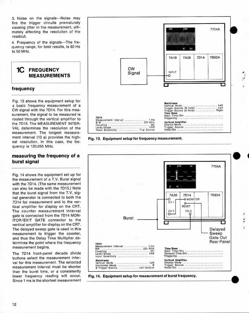
Phase shift is critical in areas li ke servo,RF or digital system design . The mostcommon method of measuring p haseshift is to use an oscilloscope in theΧ-Υ or delayed sweep mo de. Α moreaccurate method of measuring ph ase iswith the 7D15 . To determine phase, thetime between the same voltage level ont he lea d ing an d lagging sig n als ismeasured and d ivided by α conversionfactor (Time/Degree).
For examp le, if the period of the signal(as measu red with th e 7D15) is 2 its(5 MHz), the Time/Degree conversionfactor is : 2 μs/360 degree =5.55 ns/de-gree. If th e time interval between thetwo phases is meas u red at 50 ns, thephase difference is thus : 50 ns/5.55ns/degree=9 .09 d egree of phase s hift.Fig . 12 shows the eq uipment set up forth e measurement of the ph ase shift ofα5 MHz signal . L i ke the previous p ro pa-gation delay measurement, one signalis a pplied to each trigger in put to the7D15 . Again the SOURCE I NPUT Βp ushbutton is p ressed to enable bothin pu t connectors. Both the channel Αand Β TRIGGER LEVEL controls areset to PRESET, wh ich means the trig-ger circuits will trigger on th e zerocrossover point.
Trigger arming is not re quired for thismeasurement. Merely trigger the scopeon the negative goi ng slop e of ch annel1 . This assures that the pseudo gated isplay is on the CRT. The pseudo gatedisplay in dicates t h at th e measurementis being made between the two zerocrossover points. In th is case, the timemeasured is 75.60 ns for phase shift of75.6 ns/5 .55 ns/ degree=13.8 degrees .
This method of measuring p h ase sh iftcan be used for singleshot or repetitivesign als, with accuracies of 0.125° and0.075°, respectively at 35 kHz. Severalfactors affect t h is accuracy :1 . Amp litude of the two signals-It ismore d ifficult for the 7D15 trigger cir-cuits to detect the zero crossover pointon low am p litude signals.2. Relative amp litude of the two signals-I deally both signals s hou ld be thesame am p litude .
Cloc kIn p ut
7TTLGates i nSeries
Lead ing Ph ase
I
11 CH 1
Laggi n g Phase
DelayedClock
7Α18 Ι 7D15 Ι 7Β53Α
CH Α & Β
DLY'D TR IGCH 2 ςΗ Α ARM C Fi Β
INΙ
ο
7DIs
Out putMode . . . . . . . . . . . . . . . . . . . . . . . . . . Tim Α-ΒAve rg . . . . . . . . . . . . . . . . . . . . . . . . . . . . . . Χ1000Clock . . . . . . . . . . . . . . . . . . . . . . . . . . . . . . 10 π5Gate . . . . . . . . . . . . . . . . . . . . . . . . . . . . . . . Norm
Time BaseDisplayed Wavefor m . . . . . . . . . . Pse udo Gate
Main Ti me/Div . . . . . . . . . . . . . . . . . . . . . . . . . . .Trigger Level . . . . . . . . . . . . . . . 50% Amp lit ud e
Delayed Ti me/Div . . . . . . . . . . . . . . . . . . . . . . . . .Slo p e Α & Β . . . . . . . . . . . . . . . . . . . . . . . . . . +
Triggering
. .Coup l Α & Β . . . . . . . . . . . . . . . . . . . . . . . . . . DC
Delaye d Trig . . . . . . . . . . Runs After Dly TimeSo urce . . . . . . . . . . . . . . . . . . . . . . . . . . . Input Β
Vertical Am p lifierMai nframe
Disp lay Mode . . . . . . . . . . . . . . . . . . . . AlternateVertical M od e . . . . . . . . . . . . . . . . . . . Alte r nate
Trigger So u rce . . . . . . . . . . . . . . . . . . . . . . C h 1T r igge r Sou r ce . . . . . . . . . . . . . . . . . . . . . . . Left
Volts/Div . . . . . . . . . . . . . . . . . . . . . . . . . . . . . . . .
Fig . 11 . Eq ui pment setup for propagation delay measurement.
Fig . 12 . Equipment setup for phase shift measurement .
7603
7Α18 Ι 7D15 Ι 7Β53Α
ο
DelayedSweepGateOut
Mai nfr ame7 ρης
Ve r tical Mo d e . . . . . . . . . . . . . . . . . . . Alte r nateMode . . . . . . . . . . . . . . . . . . . . . . . . . . Ti m Α-ιΒ
Trigger So u rce . . . . . . . . . . . . . . . . . . . . . . . LeftAverg . . . . . . . . . . . . . . . . . . . . . . . . . . . . . . 1000Χ
Time BaseCloc k . . . . . . . . . . . . . . . . . . . . . . . . . . . . . 10 π s
Mai n Ti m e/Div .Gate
. . . . . . . . . . . . . .. . . . . . . . . . . . . . . . . Norm
I r igge r ing
- . . . . . . . . . . . . . . . . . . . . . . . . .. . . . . . . . . . . . . . . . . . . . . . . . . . . . . . .Disp laye d W aveform Pseudo Gate. . . . . . . . . .
Trigge r L evel . . . . . . . . . . . . . . . . . . . . . . Preset
Vertical Amp lifierSlope Α & Β . . . . . . . . . . . . . . . . . . . . . . . . . . . +
Disp lay Mode
. . . . . . . . . . . . . . . . . . . . . . ALTCουρΙ Α & Β . . . . . . . . . . . . . . . . . . . . . .
.
. . .AC
Trigge r So urce . . . . . . . . . . . . . . . . . . . . . . Ch 1So ur ce . . . . . . . . . . . . . . . . . . . . . . . . . . .I n put Β
V olts/Div . . . . . . . . . . . . . . . . . . . . . . . . . . . . . . . .
3. Noise on the signals-Noise mayfire the trigger circuits p rematurelycausing j itter in the measuremen t, ulti-mately affecting the resolution of thereadout.
4 . Frequen cy of the signals-T h e fre-quency ran ge, for best results, is 60 Hzto 50 MHz .
FREQUENCYMEASUREMENTS
frequency
Fig . 13 shows the equ i pment setup forα basic frequency measurement of αCW signal with the 7D14 . For this mea-su rement, the signal to be measured isrouted throug h the vertical am p lifier toth e 7D15. The MEAS UREMENT I NTER-VAL determines the resolution of th emeasu rement. The longest measure-ment interval (10 s) provides the high-est resolution . In this case, the fre-q uency is 120.055 MHz.
measuring the frequency of αburst signal
Fig . 14 shows the equ ipment set up forthe meas u rement of α T.V. Burst signalwith the 7D14. (The same measurementcan also be made with the 7D15.) Notethat the burst signal from the T.V. sig-nal generator is connected to both the713114 for measurement and to the ver-tical amplifier for d isp lay on the CRT.Th e co u nter measurement i n tervalgate is connected from the 7D14 MON-ITOR/EXIT GATE connector to thevertical am p lifier for d isplay on the CRT.The delayed sweep gate is used in th ismeasu rement to trigger the counter,and th us the Delay Time Mu ltip lier . de-termines the point where the frequencymeasurement begi ns.
Th e 7D14 front-panel decade dividebuttons select the measurement inter-val for th is measurement. The selectedmeasurement i nterval must be shorterthan the burst time, or α consistentlylower frequency reading will occur.Since 1 ms is the shortest measurement
CWSignal
Burst
7Α19 i 7Α26 i 7D14 i 7 1392Α
I NPUTο
Fig . 13 . Equipment setup for frequency measurement.
μριΙμιιΙΙιιιμΙΙΙ f
ν , Sπκ
se
MONITO R
FVCΗ 1FT-00
I
RESET
CH 2
Ι
CHQA
Fig . 14 . Equipment setup for measurement of burst frequency.
7704Α
Mainfr ameVertical Mode . . . . . . . . . . . . . . . . . . . . . . . . LeftTr igge r So urce (B Hole) . . . . . . . . . . . . . . . LeftTrigge r So urce ( Α H ole) . . . . . . . . . . . . . . Rig h tTime BaseMai n Time/Div . . . . . . . . . . . . . . . . . . . . . . . . . . .
71314
Triggeri n g . . . . . . . . . . . . . . . . . . . . . . . . . . . . . . . .Measurem e n t I n te rval . . . . . . . . . . . . . . . . 1 msΒ W . . . . . . . . . . . . . . . . . . . . . . . . . . . . . 525 MHz
Vertical Amplifie rCoupli ng . . . . . . . . . . . . . . . . . . . . . . . . . . . . . DC
Display Mode . . . . . . . . . . . . . . . . . . . . . . . . . . . . .Level/Slope . . . . . . . . . . . . . . . . . . . . . . . . . VAR
Trigger Source . . . . . . . . . . .I nput Se nsitivity . . . . . . . . . . . . . . Trig So urce
Volts/Div . . . . . . . . . . . . . . . . . . . . . . . . . . . . . . .
7704Α
7Α26 7D14
7 1392Α
Ο
DelayedSweepGate OutRear Panel
71314Meas u reme n t I nterval . . . . . . . . . . . . . . . . 1 msBW . . . . . . . .
.. . . . . . . . . . . . . . . . . . . . 525 MHz
Time BaseCoup li ng . . . . . . . . . . . . . . . . . . . . . . . . . . . . DC
Mai n Time/Div . . . . . . . . . . . . . . . . . . . . . . . . . . .Level/Slope . . . . . . . . . . . . . . . . . . . . . . . . . VA R
Delaye d Time/Div . . . . . . . . . . . . . . . . . . . . . . . . .Input Sensitivity . . . . . . . . . . . . . . . . . . . . . . . . . .
Triggeri ng . . . . . . . . . . . . . . . . . . . . . . . . . . . . . . . .
Mai nf rame
Vertical AmplifierVe r tical Mod e . . . . . . . . . . . . . . . . . . . . . . . Left
Display Mo de . . . . . . . . . . . . . . . . . . . . . . . . . . . . .Horizontal Mode . . . . . . . . . . . . . . . . . . . . . . . . Β
Trigge r Source . . . . . . . . . . .Β T r igge r So urce . . . . . . . . . . . . . . Left Ve rtical
Volts/Div . . . . . . . . . . . . . . . . . . . . . . . . . . . . . . . .
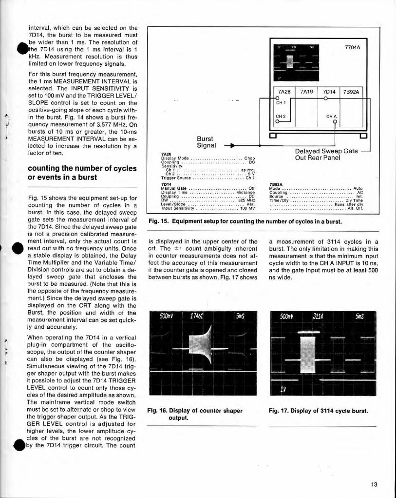
interval, which can be selected on the7D14, the burst to be measured mustbe wider than 1 ms . The resol ution of
*he 7D14 using th e 1 ms interval is 1kH z. Measurement resolution is thuslimited on lower frequency signals.
For this burst freq uen cy measurement,the 1 ms MEASUREMENT I NTERVAL isselected . The I NPUT SENSITIVITY isset to 100 mVand theTRIGGER LEVEL/SLOPE control is set to count on thepositive-going slope of each cycle with-in the burst. F ig . 14 shows α bu rst fre-quency measurement of 3.577 MHz. Onbursts of 10 ms or greater, the 10-msMEAS UREMENT I NTERVAL can be se-lected to increase the resolution by αfactor of ten .
counting the number of cyclesor events in α burst
7Α26Dis p lay Mo d e . . . . . . . . . . . . . . . . . . . . . . . C h o pCo up ling . . . . . . . . . . . . . . . . . . . . . . . . . . . . . DCSe n sitivityC h 1 . . . . . . . . . . . . . . . . . . . . . . . . . . . . as re q .C h 2 . . . . . . . . . . . . . . . . . . . . . . . . . . . . . . . 5 V
Trigge r So urce . . . . . . . . . . . . . . . . . . . . . . . C h 1
BurstSignal
7Α26 7Α19 7D14 7Β92Α
CH 1
σCH A
7704Α
Delaye d Sweep GateOut Rear P anel
7D14
7Β92ΑManual Gate . . . . . . . . . . . . . . . . . . . . . . . . . . Off
Mo de . . . . . . . . . . . . . . . . . . . . . . . . . . . . . . . A utoDisplay Ti me . . . . . . . . . . . . . . . . . . . . M i drange
Coup li ng . . . . . . . . . . . . . . . . . . . . . . . . . . . . . AC
Fig. 15 SNOWS the equipment Set-Ufor
Coup li n g . . . . . . . . . . . . . . . . . . . . . . . . . . . . . DC
Source . . . . . . . . . . . . . . . . . . . . . . . . . . . . . . Ιη t.ρ
Βω . . . . . . . . . . . . . . . . . . . . . . . . . . . . . . 525 MHz
τime/ οι y . . . . . . . . . . . . . . . . . . . . . . . . D ι y TimeCounting the n u mber of Cycles i n α
Ι
Level/Slo pe . . . . . . . . . . . . . . . . . . . . . . . . . V ar.
. . . . . . . . . . . . . . . . . . . . . . . . . . . . Ru ns afte r d lyInput Sensitivity . . . . . . . . . . . . . . . . . . . 100 MV
. . . . . . . . . . . . . . . . . . . . . . . . . . . . . . . . . . Alt . Off .burst . In t h is case, the delayed sweepgate sets th e measurement interval of
Fig . 15 . Equipment setup for cou nting the number of cycles in α burst.the 7D14 . Si nce the delayed sweep gateis not α precision calibrated measure-ment interval, οηΙγ t he actual count is
is d isplayed in the u pp er center of the
α measurement
fO 3114 cycles in α" read out with no frequency units. Once
crt. The ±1 count ambiguity inherent
burst. The only limitation in making thisα stable d isplay is obtained, the Delay
in cou n ter measurements does not af-
measurement is that the minimum inputTime M ultiplier and the Variable Time/
fect the accuracy of this measu rement
cycle width to th e CH Α I NPUT is 10 ns,Division controls are set to obtain α de-
if the counter gate is o pened and closed
and the gate input must be at least 500layed sweep gate that encloses the
between bursts as shown . Fig . 17 shows
ns wi de.burst to be measured . (N ote that this isthe opposite of the frequency measure-ment.) Sin ce the delayed swee p gate isd isplayed on the CRT along with theBurst, the position and width of themeasurement interval can be set quick-ly and accurately .
Wh en operating the 7D14 in α verticalplug-in compartment of the oscillo-scope, the output of the counter s h apercan also be d isplayed (see F ig . 16) .Simultaneo us viewin g of the 7D14 trig-ger shaper output with the burst makesit possible to adj ust the 7D14 TRIGGERLEVEL control to count only those cy-cles of the desired amplitude as shown.The mainframe vertical mode switchmust be set to alternate or c hop to view
Fig . 16 . Display of counter shaper
Fig . 17. Display of 3114 cycle burst.the trigger shaper output . As the TRIG-
output.GER LEVEL control is ad j usted forhigher levels, the lower amp litude cy-cles of the bu rst are not recognized~by the 7D14 trigger circuit. The count
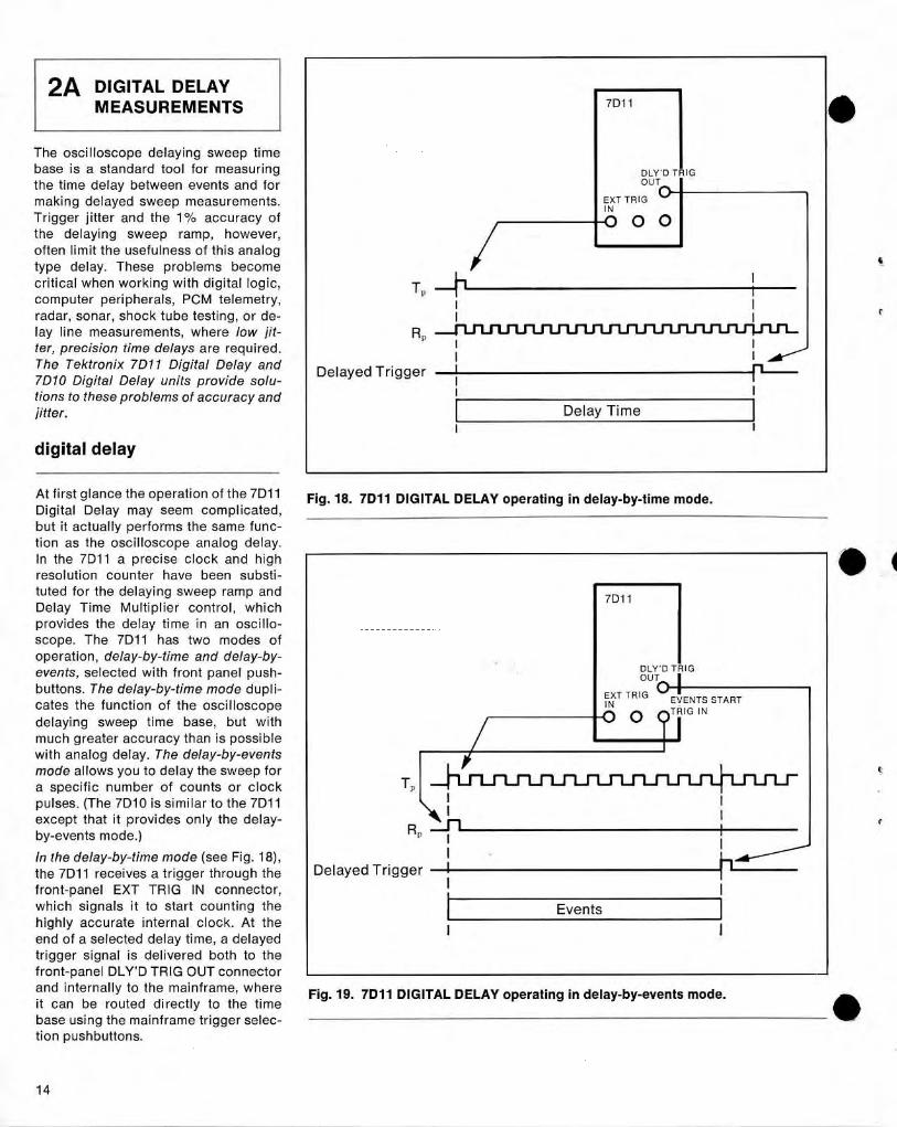
The oscilloscope delaying sweep timebase is α standard tool for measuringthe time delay between events and formaking delayed sweep measurements .Trigger jitter an d th e 1%ο accuracy ofthe delaying sweep ramp , however,often limit the usefulness of this analogtype delay . These problems becomecritical when working with d igital logic,com puter peripherals, PCM telemetry,radar, sonar, shock tube testing, or de-lay line measurements, where low f it-ter, precision time delays are req uired .The Tektronix 7D11 Digital Delay and7D10 Digital Delay units provide solu-tions to these problems of accuracy andjitter .
At first glance the operation of the 7D11Digital Delay may seem com plicated,but it actually performs the same func-tion as the oscillosco pe analog delay .In the 7D11 α p recise clock an d highresol ution counter have been su bsti-tuted for the delaying sweep ram p andDelay Time M ulti p lier control, whichprovides the delay time i n an oscillo-scope. T he 7D11 has two modes ofoperation, delay-by-time and de lay-by-events, selected with front p anel pushbuttons . The delay-by-timemode dupli-
cates the function of the oscillosco pedelaying sweep time base, but withmuch greater accuracy th an is possiblewith analog delay . The delay-by-eventsmode allows you to delay the sweep forα specific n umber of counts or cloc kpulses . (The 7D10 is similar to the 7D11except that it p rovides only the delay-by-events mode .)
1η the delay-by-time mode (see Fig . 18),the 7D11 receives α trigger through thefront-panel ΕΧΤ TRIG IN connector,which signals it to start counting t heh igh ly accurate internal clock. At t heen d of α selected delay time, α delayedtrigger signal is delivered both to thefront-panel DLY'D TRIG OUT con n ectorand i nternally to the mainframe, whereit can be routed directly to the timebase using the mainframe trigger selec-tion p ush buttons.
2Α DIGITAL DELAYMEASUREMENTS
digital delay
Τ�
R�
Delaye d Trigger
Ι
Delaye d TriggerΙ
Events
7D11
Delay Time
Fig. 18. 7D11 DIGITAL DELAY operating in delay-by-time mode.
7D11
ιΙ
DLY'D TRIGOUT
ΕΧΤ TRIG C)'EVEN TS~
IN
STARTΟ
?
T
I
RIG IN
Fig . 19 . 7D11 DIGITAL D ELAY operating in delay-by-events mode.
The delay time is selected with thefront panel DELAY TIME OR EVENTS
d F I NE DELAY controls . For conve-J
nence, th e setting of the DELAY TIME
OR EVENTS control is displayed on theoscilloscope crt readout.
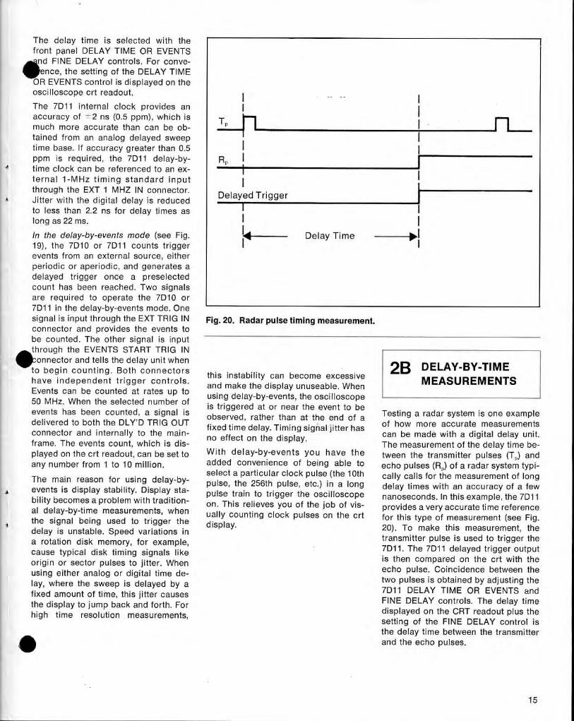
The 7D11 internal cloc k provi des anacc u racy of --2 ns (0.5 ppm), wh ich is
Τmuch more accurate than can be ob-tained from an analog delayed sweeptime base . If accuracy greater th an 0.5ppm is req uired , the 7D11 delay-by-
RP Ιtime clock can be referenced to an ex-ternal 1- MHz timing sta n d ard i nput
Ιth rough the ΕΧΤ 1 ΜΗΖ IN connector.
Delayed TriggerJ itter with the d igital delay is red ucedto less tha n 2.2 ns for d elay times as
Ιlon g as 22 ms .
1η the delay-by-events m ode (see Fig .
Ί---
Delay Time
-j,19), the 7D10 or 7D11 counts triggerevents from an extern al source, eitherperiodic or aperiod ic, and generates αdelayed trigger once α preselectedco unt has been reached . Two signalsare req uired to operate the 7D10 or7D11 in the delay-by-events mode . Onesignal is in put throug h the ΕΧΤ TRIG IN
Fig . 20 . Radar pulse timing measurement.connector an d p rovi des t h e events tobe cou n ted . The other signal is in putthroug h th e EVENTS START TRIG ΙΝ ,-------------. onnector and tells the delay u nit when
GB
p ELAY-ΒΥ -ΤΙΜΕto begin counting . B oth connectors
this instability can become excessiveh ave in d e p en d ent trigger controls .
and make t he d isplay unuseable When MEASUREMENTS.50 MH zEvents can be counted at rates up to
using d elay-by-events, the oscilloscope, When the selected number of
is triggere d at or near the event to beevents has been cou nted , α signal is
observed , rather than at the end of α
Testing α radar system is one exam pledelivered to both the DLY'D TRIG OUT
fixed time d elay . Timing signal j itter has
of how more accurate measurementsconnector an d i n ternally to the main-
no effect on the d isplay.
can be made with α d igital delay unit .frame. The events count, which is d is-
The measurement of the d elay time be-played on the crt readout, can be set to
With delay-by-events you have t h e
tween the transmitter pulses (Τ) an dany number from 1 to 10 million .
added convenience of being able to
echo pulses (R) of α radar system typ i-select α particular clock pulse (the 10thc αΙΙγ calls for the measurement of longThe main reason for usi ng delay-by- pulse, the 256th pulse, etc. in αlong
is disp lay stability . Disp lay sta-
ρ
)
g d elay times wit h αη accuracy of α fewb ί lity becomes α p roblem with trαd ί t ί α-
pulse train to trigger the oscilloscope
nanosecon ds. Ιη this exam p le, the 7D11οη . Th is relieves you of the job of vis-
p rovides α very accurate time referenceαΙ d elay-by-time measurements, when
υαΙΙγ counting cloc k pulses οη the crt
for this type of measurement (see F ig .the sign al b eing used to trigger the d isplay.
20). Το make this measurement, thed elay is unstable . Speed variations inα rotation d isk memory, for example,
transmitter pulse is used to trigger the
cause typ ical d is k timing signals li ke
7D11 . The 7D11 delayed trigger output
origin or sector p u lses to j itter. Wh en
is t hen compared οη the crt with theusing either analog or d igital time d e-
echo pulse . Coincidence between theΙαγ, where the sweep is delayed by α
two pulses is obtained by ad j usting thefixed amount of time, this j itter causes
7D11 DELAY ΤΙΜΕ OR EVENTS and
the d isplay to jum p back απd forth. For
F I NE DELAY controls . The delay time
high time
resolution
measurements
d isp layed οη the CRT readout p lus the,
setting of the F I NE DELAY control isthe delay time between the transmitter
,-
an d th e ec h o pulses.
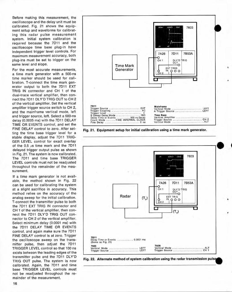
Before making this measurement, theoscilloscope and the delay unit must becalibrated . Fig . 21 shows the equi p-ment setu p and waveforms for cali b rat-ing t h is rad ar p u lse measurementsystem . Initial system calibration isrequired because the 7D11 and theoscilloscope time base plug-in haveinde pendent trigger level controls . Formaximum measurement accuracy, bothp lug-ins must be set to trigger on thesame level and slope.For th e most acc urate meas u rements,α time mark generator with α 500-nstime marker should be used for cali-bration . Τ-connect the time mark gen-erator outp ut to both the 7D11 ΕΧΤTRIG IN connector and CH 1 of thedual-trace vertical amp lifier, then con-nect th e 7D11 DLY'D TRIG OUT to CH 2of the vertical amp lifier . Set the verticalamp lifier trigger source switch to CH 2,and the mainframe vertical mode, leftand trigger source, left . Select α 500-nsdelay (0.0005 ms) with the 7D11 DELAYTIME OR EVENTS control, and set theFI NE DELAY control to zero . After set-ting the time base trigger level for αstable d isplay, adju st the 7D11 TRIG-GER LEVEL control for exact overlayof the 0.5 μs time mark and the 7D11delayed trigger output pulse as shownin F ig . 21 . The system is now cali brated .Th e 7D11 an d time base TRIGGERLEVEL controls must not be read j ustedth roughout the remainder of the mea-surement .
16
Time MarkGenerator
5ά0+ν ~ ~QbSI '~, 54#ι5''.
IN
7603
7Α26 7D11 712153ΑοCH 1
DLY'D TRIGOUT
ΕΧΤ TRIGΟΟCH 2
7011
MainframeTrigge r Source . . . . . . . . . . . . . . . . . . . . . . . ΕΧΤ
V ertical Mode . . . . . . . . . . . . . . . . . . . . . . . LEFTTrigger Coup ling . . . . . . . . . . . . . . . . . . . . . . AC
Α T rigger So u rce . . . . . . . . . . . . . . . . . . . . LEFTTrigger Level . . . . . . . . . . . . . . . . . . . . . . . .
..+
Β Sweep Delay Mode . . . . . . . . . . . . . . . . . . IND
Time BaseDelay Time or Events . . . . . . . . . . 500 ns Delay
Vertical Amplifier . . . . . . . . . . . . . . . . . . . . . . . . .Count Mode . . . . . . . ΤΙΜΕ INTERNAL CLOCK
Trigger Source . . . . . . . . . . . . . . . . . . . . . . CH 2Fine Delay . . . . . . . . . . . . . . . . . . . . . . . . . . 0 ns
Vertical Mode . . . . . . . . . . . . . . . . . . . . . . . .ALT
Fig . 21 . Equipment setup for initial calibration using α time mark generator.
If α time mark gen erator is not avail-able, the method s h own in Fig . 22
7Α26
7D11
7Β53Αcan be used for calibrating the systemat α slight sacrifice in accuracy. Th is
CH 1
DLY'D TRIG
method relies on the accuracy of t h e
OUT
analog sweep for th e initial calibration .
Radar
(Τ )
Ε Τ TR IGΤ-connect the transmitter p ulse to both
Ρ
CH 2
ο ο
the 7D11 ΕΧΤ TRIG IN conn ector an dCH 1 of the vertical am p lifier, then con -
(T)nect the 7D11 DLY'D TRIG OUT con-nector to CH 2 of the vertical am p lifier.Select minimum delay (0.0001 ms) withthe 7D11 DELAY TIME OR EVENTScontrol, and again ma ke sure the 7D11F INE DELAY control is at zero . Trigger
7ρ11the oscilloscope swee p on the trans-
Delay Time or Events . . . . . . . . . . . . 0 .0001 ms
mitter
p ulse,
then
adjust the
7D11
(same as F ig . 21)7603
7Α2ΒTRIGGER LEVEL control so that 100 ns
Vertical Mode . . . . . . . . . . . . . . . . . . . . . . LEFT
Vertical Mode . . . . . . . . . . . . . . . . . . . . . . . . ALT
exists between the leading edges of the
Trigger Source . . . . . . . . . . . . . . . . . . . . . . LEFT
Trigger Source . . . . . . . . . . . . . . . . . . . . . . CH 1
transmitter p ulse and the 7D11 DLY'DTRIG OUT pulse . The system is now
Fig . 22. Alternate method of system calibration using the radar transmission puls~
calibrated . Again, the 7D11 and timebase TRIGGER LEVEL controls mustnot be read j usted th ro ughout the re-mainder of the measurement.
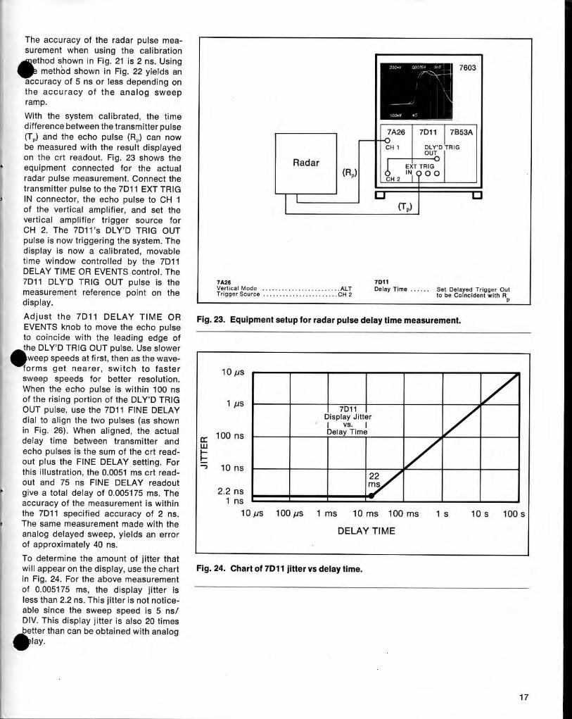
The accuracy of the radar pulse mea-su rement when using the cali bration
thod shown in Fig. 21 is 2 ns. U sing1W
emethOd shown i n Fig . 22 yields an
accuracy of 5 ns or less depen ding onthe accuracy of t he a nalog sweepramp .W it h the system cali brated , the timedifference between the transmitter pulse(Τ) and th e ec ho pulse (R) can nowbe measured with the result d isplayedon the crt readout. Fig . 23 s h ows theequipment connected for the actualradar pulse measurement. Connect thetransmitter pulse to the 7D11 ΕΧΤ TRIGIN connector, the ec ho pulse to CH 1of the vertical amp lifier, and set thevertical am p lifier trigger source forCH 2. The 7D11's DLY'D TRIG OUTpu lse is now triggering the system . Th edisplay is now α calibrated , movabletime window controlled by the 7D11DELAY TIME OR EVENTS control. The7D11 DLY'D TRIG OUT pulse is themeasurement reference point on thedisplay.
Ad ju st t he 7D11
DELAY TIME OR
Fig, 23. Equipment setup for radar pulse delay time measurement.EVENTS knob to move the echo pulseto coincide with the leading edge ofthe DLY'D TRIG OUT pulse . Use slowerwee p speeds at first, then as the waveforms get nearer, switch to faster
10 μssweep speeds for better resolution.When the echo pulse is with in 100 nsof the risi ng portion of the DLY'D TRIG
1 μSOUT p ulse, use the 7D11 F INE DELAY
Ι
7D11 Ιdial to align the two pulses (as shown
Display ,litte rΙ vs . Ιin Fig . 26) . When aligned , the actual
1 ρ0
Delay Timeηsdelay time between transmitter andec ho pulses is th e su m of the crt read-out plus the F INE DELAY setti ng . For
10 nsthis illustration , the 0.0051 ms crt read-
22out and 75 ns F INE DELAY readout
msgive α total delay of 0.005175 ms . The
2.2 n saccuracy of the measurement is with in
1 nsthe 7D11 specified accuracy of 2 ns.
10 μs
100 μs
1 ms
10 ms
100 ms
1 s
10S
100SThe same measurement made with theanalog d elayed swee p , yields an error
DELAY TIMEof app roximately 40 ns .
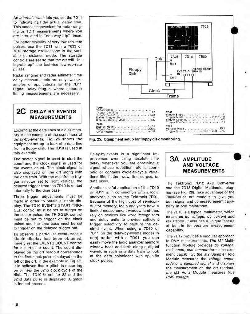
To determine the amount of j itter thatwill appear on the display, use the charti n Fig . 24 . For the a bove measurementof 0.005175 ms, the d isplay j itter isless than 2.2 ns . Th is jitter is not notice-able since the sweep speed is 5 ns/DIV. T h is display j itter is also 20 timesbetter than can be obtai ned with an aloggΙαγ.
Radar
7Α26
713111Vertical Mode . . . . . . . . . . . . . . . . . . . . . . . ALT
Delay Time . . . . . .
Set Delayed Trigger OutTrigger Source . . . . . . . . . . . . . . . . . . . . . . . ςΗ 2
to be Coincident with RΡ
F ig . 24 . Chart of 7D11 jitter vs delay time.
(R) i
ιιδΗ 2 ΙΝ , ? 0 ο
σ
5000
7Α26 Ι 7D11 Ι 71353Α
I GH 1
Ι
DLY'D ITRIG
ααοσs+
s+υ ; :
) ΙΙΙΙΙ~
OUTΕΧΤ TRIG
An internal switch lets you set the 7D11to indicate h alf t he actual delay time .Th is mode is convenie nt for radar rang-ing or TD R measurements w h ere youare i nterested in "one-way trip" times .
For better visi b ility of very low rep-ratepulses, use the 7D11 with α 7633 or7613 storage oscillosco pe in the vari-able persistence mod e . T h e storagecontrols are set so th at the crt will "in-tegrate up" the fast-rise low-rep-ratepulses .
Radar ran gi ng and radar altimeter timed elay measurements are only two ex-amp les of applications for the 7D11Digital Delay P lug-in, where accuratetiming measurements are necessary .
2C DELAY-BY-EVENTSMEASUREMENTS
Looking at the data lines of α d isk mem-ory is one example of t h e usefulness ofd elay-by-eve nts . Fig . 25 shows t h eequi pment set up to look at α data li nefrom α flo ppy disk . The 7D10 is used inthis example .
The sector signal is used to start thecount an d the clock signal is used forth e even ts co u nt . The cloc k signal isalso d isp layed on the crt along withthe data train . Wit h the mainframe trig-ger selector set to right vertical, thed elayed trigger from the 7D10 is routedinternally to the time base .
Th ree trigger adjustments must bemade in order to obtain α stable dis-play . The 7D10 EVENTS START TR IG-G ER control must be set to trigger onth e sector pulse ; t h e TRIGG ER controlmust be set to trigger on the clockpulse ; and the time base must be setto trigger on the delayed trigger out .
To observe α particular event, once αstable d is p lay h as been obtained ,merely set the EVENTS CO UNT co ntrolfor α particular count. The count dis-played on th e crt reado ut correspondsto the first cloc k p ulse d is played on theleft of the crt . In t he exam ple in F ig . 25,it is believed th at α glitch is occurri n gon or near the 82nd clock cycle of thedisk . The 7D10 is set for 82 an d the82nd d ata pulse is disp layed . Α glitchis indeed p resent .
F lo p pyDisk
71370T r igge r Slo p e . . . . . . . . . . . . . . . . . . . . . . . . . . +T r igge r Coupling . . . . . . . . . . . . . . . . . . . . . . AC
7Β80T r igge r Sour ce . . . . . . . . . . . . . . . . . . . . . . . ΕΧΤ
Tr igge r Slo p e . . . . . . . . . . . . . . . . . . . . . . . . . . +Eve n ts Trigger Sta r t . . . . . . . . . . . . . . . . . . . +
Trigge r M o d e . . . . . . . . . . . . . . . . . .
Ρ - Ρ AUTOΒ Sweep Dis play Mo d . . . . . . . . . . . . . . . . I N D
Trigger Coupli n g . . . . . . . . . . . . . . . . . . . . . . ACT r igge r Source . . . . . . . . . . . . . . . . . . . . . . . . ΙΝΤ
7Α26Display Mode . . . . . . . . . . . . . . . . . . . . . . C HO P
7603T r igge r So ur ce . . . . . . . . . . . . . . . . . . . . . MODE
Vertical Mode . . . . . . . . . . . . . . . . . . . . . . . LEFTCH 2 Pola r ity . . . . . . . . . . . . . . . . . . . . . . . + UP
Trigge r So u rce
. . . . . . . . . . . RIGHT VERTICAL
Fig . 25 . Equipment setup for floppy disk monitoring .
Delay-by-events is α significant im-provemen t over using absol ute timedelay, whenever you are observing αsignal whose repetition rate is aper ί -odic or contains cycle-to-cycle varia-tions li ke flutter, wow, line surges, ordata skew . The Tektronix 7D12 Α/D ConverterAnother useful a pp lication of the 7D10
and the 7D13 Digital Multimeter plug-or 7D11 is in con j unction with α logic
ins (see Fig . 26), take advantage of theanalyzer, such as the Tektron ix 7D01 .
7000-Series crt readout to give youBecause of the h igh cost of semicon-
both sign al and do measurement capa-d uctor memory, logic analyzers have α
bility in one mainframe .limite d measurement window, an d thus
The 7D13 is α typical m ultimeter, w h ichrely on devices li ke word recognizers
measures do voltage, do current andan d delay units to provi de sufficient
resistan ce . It also h as α uni que featuretrigger selectivity to capture the de-
of built-in temperature measurementsired even t . When using α 7D10 or
capability .7D11 (in the delay-by-events mode) inconjunction wit h α 7D01, you can
The 7D12 p rovi des α mod ular app roac h
easilv move the loaic analvzer memorv
to DVM measurements . The Μ 1 M ulti-
wi ndow bac k and forth along α digitalwaveform such as α data train to lookat the data coinci den t with specificcloc k pulses .
Data
σClock `~-
Frame
_~ί_ ι
i
_-
rι-Ϊ.~_
ιι ®
EVENTS STARTΕΧΤ TR IG T R IG IN
Ι
3Α AMPLITUD EAND VO LTAG EMEASUREMENTS
function Module p rovides do voltage,resistance, and temperature measure-ment capability ; the Μ2 Sam ple/ HoldModule measures the voltage ampli-tude of α sampled signal and displaysthe meas u rement on the crt readout ;the Μ3 Volts Mod ule measures trueRMS voltage.
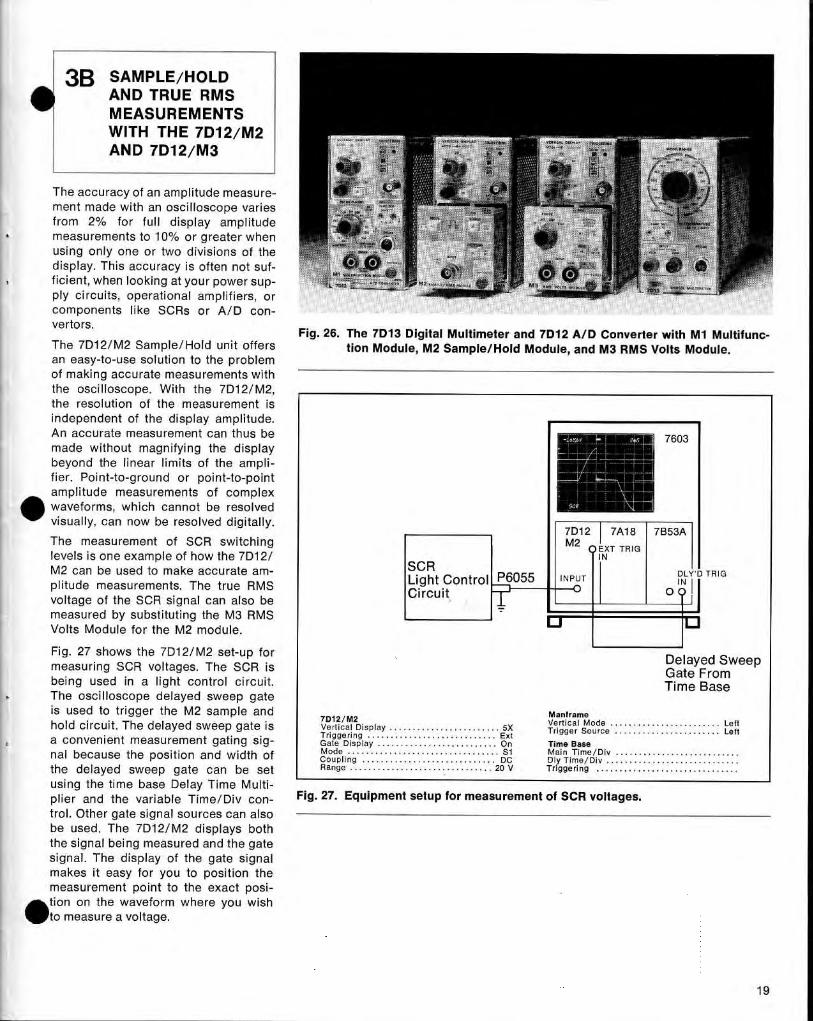
3Β SAMPLE/HO LDAND TRUE RM SMEASUREMENTSWITH THE 7D12/M2AND 7D12/M3
Th e accuracy of an amp litu de meas u re-ment made with an oscilloscope variesfrom 2% for full display amp litudemeasurements to 10% or greater whenusing only one or two divisions of thed isp lay. T h is accuracy is often n ot suf-ficient, when looking at you r power sup-p ly circuits, operational am p lifiers, orcom ponents li ke SCRs or Α/D con-vertors .
The 7D12/M2 Sample/Hol d unit offersan easy-to-use solution to the problemof maki ng accurate meas u rements withthe oscilloscope. W it h th e 7D12/M2,the resolution of the measurement isind ependent of the display amp litude.An accurate measurement can th us bemade without magnifying the d isplaybeyon d th e li near limits of the am p li-fier . Point-to-ground or point-to-pointamp litude measurements of complexwaveforms, wh ich can not be resolvedvisually, can now be resolved d igitally.
The measurement of SCR switchinglevels is one example of how the 7D12/Μ2 can be used to make accu rate am-p litu de measu rements . The true RMSvoltage of the SCR signal can also bemeasured by substituting the Μ3 RMSVolts Module for the Μ2 module .
F ig . 27 shows the 7D12/M2 set-up formeasuring SC R voltages . The SCR isbei ng used in α light control circuit .The oscilloscope d elaye d sweep gateis used to trigger the Μ2 samp le an dhold circuit . The delayed sweep gate isα convenient measurement gating sig-nal because the position and width ofthe delayed sweep gate can be setusing the time base Delay Time M ulti-p lier and t he variable Time/Div con-trol . Other gate signal sources can alsobe used . The 7D12/M2 d isplays bothth e signal being measured and the gatesignal . The display of the gate sign almakes it easy for you to position themeasurement point to the exact posi-tion on the waveform where you wishto measure α voltage.
Fig . 26 . The 7D13 Digital Multimeter and 7D12 Α/D Converter with Μ1 Multifunc-tion Module, Μ2 Sample/Hold Modu le, and Μ3 RMS Volts Module.
SC RLight Control P6055
INPUT
Ci rcuit
7D12 Ι 7Α18 Ι 7Β53ΑΜ 2 Q ΕΧΤ TRIG
Ι IN
7D12/M2
Manfr ame
Ve rtical Display
Vertical Mode . . . . . . . . . . . . . . . . . . . . . . . . Left. . . . . . . . . . . . . . . . . . . .. . . . . . . . . . . . . . . . . . . . . . . . 5Χ
Trigger So urce . . . . . . . . . . . . . . . . . . . . . . . LeftTriggeri ng . . . . . . . . . . . . . . . . . . . . . . . . . . . . E xtGate Display . . . . . . . . . . . . . . . . . . . . . . . . . . On
Time BaseMode . . . . . . . . . . . . . . . . . . . . . . . . . . . . . . . . . S1
Mai n Time/Div . . . . . . . . . . . . . . . . . . . . . . . . . . .Coup ling . . . . . . . . . . . . . . . . . . . . . . . . . . . . . DC
Dly Time/Div . . . . . . . . . . . . . . . . . . . . . . . . . . . . .Range . . . . . . . . . . . . . . . . . . . . . . . . . . . . . . . 20 V
Trigge ring . . . . . . . . . . . . . . . . . . . . . . . . . . . . . . .
Fig . 27. Equipment setup for measurement of SCR voltages .
7603
DLY'D TR IG
ο 0 .~
Delayed Swee pGate F romTime Base
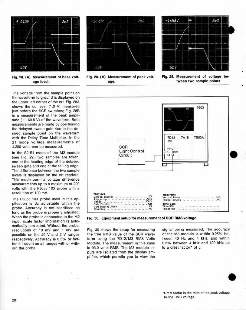
Fig . 28. (Α) Measurement of base volt-
Fig . 28 . ( Β) Measurement of peak volt-
Fig . 29 . Measurement of voltage be-age level.
age.
tween two sample points .
The voltage from the sample point onthe waveform to ground is d isplayed onthe upper left corner of the crt . F ig . 28Αshows the do level (1 .0 V) measuredj ust before the SCR switches ; Fig . 28Βis α measurement of t h e peak amp li-tude (+169.8 V) of the waveform . Bothmeasurements are made by positioningthe delayed swee p gate rise to the de-sired sam ple poi nt on the waveformwith the Delay Time Multip lier . In theS1 mode voltage measuremen ts of±200 volts can be measured .
In the S2-S1 mode of the Μ2 mod ule(see Fig . 29), two sam ples are taken,one at the leading edge of the delayedsweep gate and one at the falling edge .T h e difference between the two samplelevels is displayed on the crt readout .Th is mode permits voltage d ifferencemeasu rements up to α maximum of 200volts with the Ρ6055 10Χ probe with αresol u tion of 100 mV.
20
-50Υ
INPUT ΙH IGH COM
7603
7D12 7Α18 7Β53ΑΜ3
7D12/M3
Mai n fr ameVe rtical Dis p lay . . . . . . . . . . . . . . . . . . . . . . . . 5Χ
"~rt ίοα 1 Mo de
Left. .
. . .The Ρ6055 10Χ probe used in this αρ -
Tr igge ri n g . . . . . . . . . . . . . . . . . . . . . . . . . . . Auto
Trigger source . . . . . . . . . . . . . . . . . . . . . LeftRange . . . . . . . . . . . . . . . . . . . . . . . . . . . . . . 200 Vplication is do ad j ustable within the
Gate Display . . : . . . . . . . . . . . . . . . . . . . . . . . Off
Time Baserobe . Accuracy is not sacrificed as
νert Dis p lay Atte n . . . . . . . . . . . . . . . . . . . . . Χ1
Time/Div . . . . . . . . . . . . . . . . . . . . . . . . . . . . . . . .probe. Accuracy
Coup li ng . . . . . . . . . . . . . . . . . . . . . . . . . . . . . AC
Triggeri n g . . . . . . . . . . . . . . . . . . . . . . . . . . . . . . .
long as the p robe is properly adjusted .Wh en the probe is connected to the Μ2
Fig. 30 . Equi pment setup for measurement of SCR RMS voltage.inp ut, scale factor information is auto-matically corrected . Without the probe,resolutions of 10 mV and 1 mV are
Fig . 30 shows the setup for measuring
signal bei ng measured . The accuracypossible on the 20 V and 2 V ranges
the true RM S value of the SC R wave-
of the Μ3 module is within 0.25% be-respectively . Accuracy is 0.5% or bet-
form using the 7D12/M3 RMS Volts
tween 40 Hz and 4 kHz, and withinter ±1 count on αΙΙ ranges with or with-
Mod ule. The measurement i n th is case
0.5% between 4 kHz and 100 kHz upout the p robe .
is 93.0 volts RMS. The Μ3 mod ule in-
to α crest factor of 5.puts are isolated from the d isplay am-p lifier, whic h permits you to view the
"Crest factor is the ratio of the peak voltageto the RMS voltage.
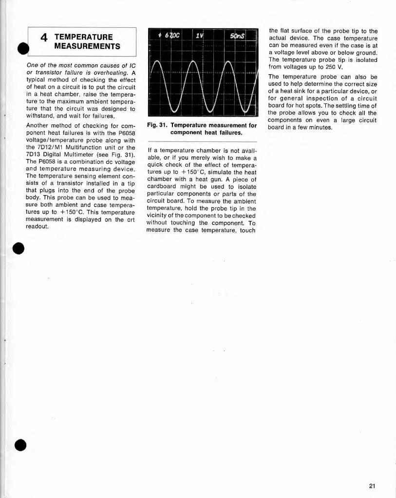
4 TEMPERATUREMEASUREMENTS
One of the most common causes of lCor transistor failure is overheating . Αtypical method of checking the effectof heat on α circuit is to put the circuitin α heat c h amber, raise the tempera-ture to the maximum ambient tempera-ture that the circuit was designed towithstand , and wait for failures .Another method of chec k ing for com-ponent heat fail ures is with the Ρ6058voltage/temperature probe along withthe 7D12/M1 M ultifunction unit or th e7D13 Digital Multimeter (see Fig . 31).The Ρ6058 is α comb ination do voltageand temperature meas u ring d evice.The temperature sensing element con-sists of α transistor installed in α ti pthat p l ugs into the end of the p robebody. This probe can be used to mea-sure both am bient an d case tempera-tures up to +150`C . This temperaturemeasurement is d isplayed on the crtreadout.
th e flat surface of the probe ti p to theactual device. The case temperaturecan be measured even if the case is atα voltage level above or below ground .The temperature probe ti p is isolatedfrom voltages up to 250 V .
The tem perature p robe can also beused to h el p determine th e correct sizeof α heat sink for α p articular device, orfor general insp ection of α circuitboard for hot spots. The settling time ofthe probe allows you to chec k all thecom ponents on even α large circuit
Fig . 31 . Temperature measurement for
board in α few mi nutes .component heat failures .
If α temperature c h amber is not avail-able, or if you merely wish to make αquick check of the effect of tempera-tures up to +150"C, simu late the h eatchamber with α heat gun. Α piece ofcard board might be used to isolateparticular components or parts of thecircuit board . To measure the am bienttem perature, h ol d the probe tip in thevicinity of thecom ponent to be checkedwithout touc hin g the component. Tomeasure the case tem perature, touch
Digital Application NotesUse the attac h ed rep ly card to request any of the appli-cation notes listed below.
Measuring time Interval Between Νοη-Ad jacent Dίg ί tα 1
Measuring D ίsc DϊΊVV AccessT;-.and Access VoltagesWord Train Pulses or M ulti-Echo Radar Pulses.
with Tektronix 7000-Series Digital Plug-ins.This app lication n ote descri bes how the 7D15 Time-
This application note demonstrates how the 7D12/M2Interval plug-in in α 7000-Series M ainframe p rovi des the
Samp le/Hold Mo dule makes voltage measu rements onability to make selective d igital time-interval measure-
any portion of α waveform accu rately with d igital reso-ments from any repetitive or non-repetitive pulse . It also
l ution to 1 mV. It also d escribes how the time betweendescribes how this combi nation can make time-interval
two points on α waveform can be accurately determine dmeasurements between non-adjacent pulses with out
using the 7D15 225 MHz Un iversal Counter/Timer .sacrificing d igital counter accuracy .
SCR Gating Waveform Measurements with H igh Reso-Counting Events i n α Burst and M easuring Burst Fre-
lution Digital Accuracy.quency .
This application note d emonstrates how you can mea-Α procedure shows you how the 7D14, 525 MHz h ig h-
sure any point on waveforms up to 220V ρ-ρ with 100 mVfrequency counter can be used to measure the fre-
resolution an d better th an 0.5% accuracy using thequency or events on any part of α waveform . Α delayed
7D12/M2 Samp le/Hold DVM. It also describes how thisgate is used to isolate the portion of the waveform to
is an excellent means to accurately measure the voltagesbe measured .
of α waveform and avoi d the difficulties of sampling
Digital Delay in an Oscilloscope Makes Your Radar
oscilloscopes and overd rive recovery problems of ver-
Pulse Time Delay Measurements Quic ker, Easier and
tical am p lifiers .
More Accurate .
Why Use Digital Events in Your Measurement Applica-This app lication note describes how to easily make delay
tions.time meas urements to within 2 ns accuracy using the
Th is app lication note demonstrates how the 7D11 Digital7D11 Digital Delay Unit .
Delay Unit gives you stable displays, eliminates trigger
M easuring M emory Core 1/Ο Signals with Digital
ambiguity and accurately determines wh ic h clock p ulse
Accuracy.
is on screen . For examp le, you would be able to tell if
T his application note d escribes how the 7D12/M2
you were on th e 1st cloc k pulse, the 129th clock pulse
Sample/Hold Module is used to make amp litu de mea-
or any clock pulse to 107.
su rements on any poi nt on α waveform with accu raciesbetter th an 0.5% . It also demonstrates how th e timebetween two points on α waveform can be measuredwith digital accuracy usi ng the 7D15 225 MHz UniversalCounter/Timer Plug-in .22
CHILE
INTERNATIONAL FIELD OFFICES DISTRIBUTORS AN D REPRESENTATIVES
~Ε RΙΑ
DENMARK
INDIA
MEXICO
REPUBLIC OF SOUTH AFRICA
THAILANDMeasurelec
Te ktronix Α/5
Hinditron Services Private Ltd .
P rotea Ph ysical & Nuclear
G. Simon Radio Company Ltd .Dκ τοασ α
d,α.
sαιαη Βουακου 'r -agsvaer
T-1- Arg σ stal $ Αea ss Α ι. υα 9mοηαηααs Marg., . .
InstrumentationΑΙ9ίειτ
Κισ9α hοΙνeΊ τ9
BambaY-4σ0bb"
(Pty.)
Ltd .
30, ΡαΓρσπ g Avenue
T-μ-, 60 .4570 απΠ 60 .45 71
Ρη eι ( σ 21 98 77 11
Ρhοπ e : 365744
DepτO. Control ds Calίdad
Ρ.Ο. θσχ 39121 Θαπ94οk(Plglers).7e ι ex'. 16482
- elax : 95}0112326
ν . JαΙιτεσ 180
Bremley 201α
Phane'. 3σθ91 -37elex: (Ριιναle lelex Ι 5 rot avallable
Gable : TCKHINO, Blob,
μΑΡd σ. ΡσsιαΙ Μ-2511, Μαπlεσ 1, Ο .F.J
746 S ι xlh Street
Cub'.α : θΙΜΟΝCΟ, Θαπ9 ΚυΚισ d αγ .)
σ 19, ο.F .
Wynbe"9. 5l απdtσπ(A(able :
ddress us α 6σνα)
412 Raj Mahxl Vilas Eztension
1-1
¢ : s1s~ θ 5 θο
Τ rαπαναΙΙEAST AFRICA (Kenya, Tanzania
Θαπg σισ r ε- τ 6 α oos
τe ι* : σν-7ατσα
Ρησπα ~. 78s-mτσΡπησα : 331 9s
c αmε : ARCOSτ A ι , vi,-
T .-and
9-usas
THE NETHERLANDSθΛ d Uganda)
τ e ι eχ : s5a-σα 3-7α 1
Αν . U π 'ινers ιd ασ 3335Nod,
7e4b οσίχ Ι1 οΙΙαΠ d N.V.ARGENTINAARG ENTINA
c αbie : 7 εκΗιΝο, Bangumre
Ρ . ο. αe
Μon ιerrey, Ν . ι.Coasin S.Α.
Engine ring & Sales Co., Ltd .Ltd .
Phone: s-13 -so~ Ριι.ηα 7azo-
Μ ;do rnweg τ
vi-, ηe ι Pin. 4071
eαπκηου se, covernment Roea
ταιeχ, o3eess
υ?. : κιυπα sι r¢ ει
'pos ι eυs 114 °AD.θοχ 4sssB)
αnQe πeιιαπα ιcασ¢ τοωη α rαπεη j
ΒααhσενεασνΡΘυeπσs At,,
Ν e ΙισρΙ, καηγα
ΙΝ DΟΝΕ$ΙΑ
οαΙχ. J. Jesus Glx . Gal' σ 383
Ρισ rιε¢ 51-3247
Ρπο .,e : 029ύθ-ύ 155Ρhαπ ¢ ι 52-3185, 51-93ύ3
Ρηππει .6015
Guadalajara, Jal.
ίeΙεχ : 5 -7 ί 55 Ι
Τ. Ι .χι 7 Θ49οΤΥιeχ : 32-229 α
Cad ιe: επ9seιαs Nelru bl
Ο . Μ, 0 ωί Τυη 99 αΙ Dj aj a
Ρπσπe : 1 τ -26-46, 17-78-12
_oeble: Γ,ΟΑ Sιμ θυαποα A�,
7.1-)68 271 σ
P.- S- 47031-
ΡΙπt υ
Air
Νσ .
9
Or ev υill11 e 1125γα Ν° 1930
υakurlu
176 Stamfnrncο
NJI ROadmοοα α
Ρησπe :46369
o υ rba,
TURKE YPhone : 51-3037
ECUADOR
cebιε '. C νονπτο J ΑJΑ
MOROCCO
-11 οσ
E r kman E le ktroni k Alefler2 sΡισ lαεσ Coasin Cia Ltda .
S πεα re ι Anomm sιι 4eαCRMΝ eεαι bev cedaes ι s2/3AUSTRA LIA
A-, s σα 0e είemm° α65 ν I�'
αο οιιαrd οιCa(Ρ . 0. Θσχ 22 ΘΑ j
IRAN
Κα " akoy, ΙσlαπδυΙTektronix Australia Pty. Limite d
ουίιο
σαδιαηεα
ΡΓ. ηη ¢ : 4+ 1 . 4 ω4π 7 ύ sαο weterισ o Rasd
Ρηοπ¢ : 5z-σ759 . 52-966α
Berke h Com pany Lt d .
Ρησπ e : τ 7 ss 11
SA UDI ARABIA
Ταιαπ : 2α5sιι ~ Μ SΕ TRΝοπh Ryde, N.S.W. 2113
Τ¢lex : 2865 ΡΛΟΤΕCΟ-ED
^0 Sulm Ruud
7elex ι 21815
Cable.
Ιπσπι.υer
Ι s ΙπεδιιΙ
5γπησγ
Cable'. PROTEGO, chit.
RoOSavelt Αν ¢πυα cαb' α: SCRM cASA (2ισι 5)
Elect ronie Eq u ί pmant Mar ketingΡποο e. 881 -6
ταπιση
Establishment2d269
Ρhσπε '. Θ2Θ294 δ -564
Ρ. 0 . Βαχ 7750Cable : ΤΕΚΤΘΟΝΙχ Αυ 5lrαΙία
Ti- 212956 BERK IR
NEW ZEALAND
Rly ααk
UNIT ED KINGDOMPlPh138 G ;Iles Street
EGYPT
Cable: ΘERKEHKAR, Tehran
W, & Ι( . McLeaΠ Lt d .
Tel.s ι 2[Ρ2~0 ' 32761
Taktrcni % UK. LimitedAl-al S-1, A .-.1. 6 Φο G ΊΖα Υ$ 6fem8e
Engineering
σ3- , α5 Felton Math,, Avenue
vertan ΗουSα. zza-291,.1 Αυb υιπ Road
Comoany
G ιειι ιr ι r,ISRA EL0, Ρ. 0eeox 3 σ97)
SINGAPORE
3s -3 Β, oold η erbour Le ηeΗαωιηο rη , νίε . s ιττ
Ρ. ο
B- 1-
Αυεκιαπα s
ss)ΙΡ ο . ΘεχΜ emσυιπι
4 ελ +es π Sir-
Eestron'ιε s Ltd.
Ρηοπ. : 537-or
Mec hanical & Combustion
~αισeπα ' η, ιια rιτΡησπα 81 059d
GI
ηοπe: Harpenden 83ι41, 51251cαπο
11 Roxan ιs sιreel
Τe ια * : Ντ 2763 κσs εν
Engineering Co. Pte . Ltd .
ται¢χ . 1-1Ρ h σπσ. IF 711 α
τ¢ ι h
Came : κ osFV, Α,ιεκιαm
eαme, τεκι RοΝιχ Ηαιρ eπα e π9 s 7278
in--Ο. Θσχ 39300)
6 "h Floσr, Wcstbroak Ηοιs α
ο - 2 . J αΙαιι ΚΙΙαπ9¢1
Ιν
ΙΡ . 1 Ο. Θοχ 45, Alxendra P- Off~ σe)AUSTRIA
Ρ παΑrπe . αι5 151
1.1 νιιιιιτ sιι¢¢ι
sΊη sανο r¢ α
ι 31 Α . M11-1, Ρααπι e*: 11
-.1
(c .
Ρ.
ο.
eο*
4ss1
Ρηοπ ¢.
E47151 BurnaseH ohd e & Sc hwarz-Te ktrOn'ιχ
τe ωc ιι ms ιοπ ι
Μαπεη eαισ r 7sGeS.m . b , H .
FE D ER A L REPUBLIC
Cable: εηs τβοινιχ τe ι ΑνΙν
υηe : 85ι -α5 σ
c, ππΕ Cόπαά . 5inqapore
Ρηεη ¢ π ααα - οιαssαηπιeιιππ eι q αsss χσ
OF GERMANY
τeιι e π : NO 3053 κosrv
Ται ¢ χ . cs9u .ιsρ -11 οο vi
Ro hde & Se hwarz
21,d Floε r, 6Λειααη αυί:αιηοποπα . -- 62 s1 α1
ITA LY
2 ιο ο χιε rα -r-
7 smeι Ηουτ <, sme ι ωσικτe ιαχ. νι c ηπα 13933
Vertriebs GmbHS Ί lverstar S
(c . Ρ . α - α °κ 2421)
ίSPAIN
^ ε randGIosse α11 9 1 ιr ατ s ε 213 217
Spa, L td.
ιπιίσιεηυνεh ι
ινίπ gσιαπ . W-1 ι
απPnare. Θα -4σα
C . R .
Mares,
S A .
Ρηπηe :
ι
π~ιση s1~~ ε s/7ς ° C
ααχ
2267
Vi le
Graactn
Νο
20. . .
enclaα Hamburg 5ο
2346 Mil.. .
V~
333Barcelone 191BELGIUM
Phone : (1411) 38 '4 66
Ρποπσ 4sss ητ ιίπ eαl
Ρησηα 2s7 ύ 2 σσ. . .τeισχ : σ
α1α
749 ~ sιι sτΑR -sιes ΜTEK T RONIX ° Cabι a : R οκοε sc βωΑRτ Hambu νg
c~ύι e . s ιινεβ sτΑR rπιιαπο ο
NIG ER IA
cα ιeιΡ : Μήάέ s ααιε e ιοπα
URUGUAYΑν. J . eeseι .ιaana2
κπα9 ατι rααασ as
'υία Ραιτιηιιπ Νσ . 3ο
Metal Engineering Co . L td.
cax ι ambιee, εσ-1°
Cπααίπ Uιιι gιιαγα S .R . L.Brussel 115σ Bruxolles
001
oma9ΘΡη °,
Ρ. ο. Θσχ 6369
Maαrld ςιι5Ρ hσπ¢ ι (7 ηί71 .9θ <¢
(Ρ75Ο. OP. 522Θ )
eR: Θ44 θθ . α t/S (f- ΙΙπε s Ι ί
Θ9 Wakeman S ΙΓΘΘΓ
C-11. a e -- Νσ. 1 ΛΟπ33 ΛΠ-1-ha-1-haTelex- 2 Γ, ϊ 3
ΡΛοπα Ιρ72'j 2 39 77
ΤcΙσχ , 61511 SILSTFR RI .,
Vaba
cιeι
41Υ332
Gorraσ CentralCαρΙ ¢ ι TEKBEL
χι 7 Θ 26 73Π
Ch-. 51LVERSTAR R-
L α9οα
Cσblc : MARES Medι 'ι d
ΡΓππ eΥ9Cα6 Ι ¢ ι RCHOESCHWAR τ -r-h . 1ρΠ739α 7 οιίσσr ο ΘTelexB216a9 ι5M
ιαυΙ ει OOAGR, Monleν7de0Seden .slrasse 13-17
ΡΛαπι α4 .3276/Β
Οαη eMpFA7EN62 LHGOSBRAZI L
5 κασιπ 1
c α ble : s ιινε RS τΑα -m,swB/1s1 ιΙα bσ uye-pass
SRI L A NKAImporlacao,
} η~π-?- ΒαΚ~°5αι z2ι 77 22 ι
οκα-Απ °
Μαυ rί c ο R oc he LimitedIn dustria e Comeo
cabι e . βοΗυεsc ΗωΑατ κπσιπ
%~άαθοχa4se
VENEZUELA
Am briex 5 . Α.
JA PAN
Ρ h σπι- 22824
c.Ρ .ο. eοχ ε 1
Ε g υιια 6, Ο. Α .er 5l ιαττα 709
Iamb.αιPi,, Ce.arα, 1σ4 2° e 3° ends .
ΒΜυ¢ πεπe π 37
Sony/Tektronix Cor poration
Ρησηe ι 25846, 25347 . 258λα
Tore κ_rJ ε οΙSσια J e Janeiro, RJ
W,επ e ι 1 081' 1 52 1 υ 41
Gabe-. L ΑΧΑΡΑΝΑ, Oclomba
� 'rdu R σπυΙσ GalegoxΡ h οπιι 260.740 Θ, 264-7625, 264-σ461
Te'e2523703
9-71, K,411-1 .9 .1 θηΊπα gαωα-Κυ
^ απ :α Εευνι gιτe αb ιε. ΡcΗοε sc κωΑΙτνεηΤ R ιεα
Τ° Κ 141
NORWAY ςΑραιιαdσ ύ 97)7elex: 391112 Ι 2 Ι 128
ιΡ.Ό~ θαg 1 ι , Haneda Airporf,
C αιαεατ 10Gable : RAIO(ARDIO, Rlo de J απαι m
Μυ e πεπ e π
ηκνη 1
gens
Ρ h σ ,= ι tΈύ ιΙrrs77
M0 r
lierne & Co
Α / S SUDAN ΟοΙχα τυ ι, s.
ΡΠοπσ. aasoτ zl ςηr εα σαποκνο .
SUDAN
ταΙ =*Ρ
Ci & Ph t Sl¢ π .02422850
κonqhe ιιesc3.nc oo upp y
Ch- -1116eo P .."SP
ΘΡηπσe
677 os, θ6 1112 ,
ι bι
οΝντεκ τ kyo
ΓΡο
α χ 6688 αοαe ιοκκα
οs ιο s ι
Com pany (CPSC)_'1a sυατο
FI NLAND
° ι
ι
Ρο Θοπ Bsa/ 7
-Ebl
Β Idlng 1 -ύ-7t. .E bInto Ο / Υ
Eb
m 3mb γ 4 υ
ΤT 1. ο
oRbF π 5 σ 7~~62 7-3
~α ακαατ 47 θ
WEST AFR ICA: zs ιπΡ ο Θοχ 157
Ρ
. .
σ-Θ
Γ . οσ /Τσκνσ)CANADA
Cc C1
Νσια ηΜ
/
τ χ
ρ τ ι
Θ
- ο
lιιιι Νο . z
-1. : ΡπαιαΚ πα
SIT ELTektronix Cana da
L td.
PP,,'Ί9σ 171123
z-1s ι s
αεηι
Ρσmιε ειαυα
ο
κιια- υ
Νsοει ° ιι ιν
¢ aeelex . 21 θ3ύ
επ
οr Ι eσιαlίεπXD s αικιικ sιισσι ιβοπι e ottica)
cαT
ρι e :
Ντο , Ηαι 5 ίη 4 ιι
οαακα-απί
PAKISTAN
2 στή ~e°ιι~~ άεπ α ιosse,
σεb¢ ε
τ3οΗ9 α
as'
Phone . 31 τ -2τ5 ι (erea 06,0-,)
Ρα 4-Lan d Cor porat'ιοη
SURINAME
er 150Αb ίαΊαη I-, dl,,,,,Ρππησ . ς51 <7 6w-5340
Ηηιe-εho-τ Naxamura-ku
ε¢ πιιαι eommarεia ι Area
Wοη
S απ
T_& Co
rooι y c ...tοασιτ eιε*- sαzι sτσ
Θ
9 .Guble : TEKANADA
FRANCE
Να9σΥα
Ρσbal Rn α d
Ρ,c πει :
α λλ t α.7 Ε581 -8 (urea 052 / Να 9 οyα)
ΕC .H- S σεΓθ lγFIELD
- < υ m ίπ Γ" α -αΓ
Ta.x . 525 1 RΑΥΘη C ΗπαιρJ πΝT EKTRONIX
ρ°°° `
καιαε h ί -τ s
2p. zo . ααχ ιs3)
OFFICES :
Ζ. Ι . Gourteboeul, OF . 13
Ρησπε '. 4373t5, 4380Θ4
erib0Montmal
91401 Orsay
(αbΙ ,ι PAKLANO, K--
ΡΓοπ e: ί3571, ί5187, 72 15 4 . 7Ε3599 ου 5εικι rk street
τπο ,e : s07 ια 27
JORDAN
Cable. sarι c τsn ι co, F ιn .ι mar ;m
Η s~l~s~l α be, 0,,b,,
C'_ι σ : τέκFάάΝΝScαey2TA REO Scientific Bureau
WEST BERLINΡΓιυπe : (514)637-5340
Gent,, Re9 ιοπαΙ deL"'
Salt Road
Rohd e & SChW'αντΤ¢ ι e χι 05.82157r,
153,Bouιevard αΑ. ειαττ-υπιs
Ρ. ο . Dr. 463
PANAMA
SWE DEN
Handels-Gm bHGub ι e : TEKANADA
89008 Lyon
Amman
Executive Marketing Corporation
Te ktronix AB
ε r ητι +c ι rer-ριοι , 1 οΡησπει (7Θ17640 .03
Ρηηπ e, α6855 Θ α 8856
g
ρΟνα [ ΊΟπ-12λ Ανeπυe S.W.
ΤεΙχ : 7EKLVON 3 0Ο15 σ
T, m .: 1611 ADER JO
Apartadn -,1
1-,.e
.
1 Β e ιΙιπ 1 σa
Alberle
CαπΟι , Re
G~ebl¢ : ADERDRUG AMMAN
Panama 5
FF οπι : Γ0311) 34 1 α ο3 ΕνΥ ,
gional de Ναπε y
ΡΓ
tiι-9354, 64-985 Ι
-7- Οα SσΙπα
Τelx ι 0 Ια1 fi7672R OJ2
1ά, ru¢ de Ια Cote
ππ e
rhone ι σθ / 8 3 σ0 80ΡΠοπ eι (4D31,269-38
S υ00 Ναπιγ
T-
--a
Geble : ΛOiGESCI ι VlARZ ΒeιΙ π
7,l,,:02Θ-21730
GuLle'. MARKE71NG ΡΑ , Ραπem α
Tele κ: 17 Θ91 7Qk5We α Sphone, (2θ )27.2α-8 Β
Cable : 7EKTROSWEO θ[ock η olm7ele *: ΤΕΚΝΑΝ Cν 850872
KOREAέάό .mη ,Α ήι eαάh
Μ{ International (Korea) Ltd.Τ "3Η 2J7
Centre Re9i σnal d'Ai*-επ -Ρισνeπεe
Kommendors9atan ύ
ΖΑΜΒΙΑ
e ι (407Ί<34-9α66
Ru¢ Le Ο arbusiστ
Ro om14 0 7 . Ccnter Θυι ldίπ 3
PERU
3- Λ 14 59 GοΦεπ bυr97 λειχ οπ-s79s
1 α 10 ο Αιχ -< π-Ρισν e πεσ
s,-1
s οκοιι 9αοπ g, chung- κυ
Ρhυπσ, υα, /4τ ια 3
-
Baird and Tatloc k (Zam b ia) Ltd .117
Ρποπ e . Ι 91)27 24 87
IC . Ρ. Ο
Θσχ.
1355)
1mp0 Γtuc i Ones y
πwe
σπαα 1111T.,
t .
Telcx 7ΕΚΑΙΧ 111145
6eau1133 ωνπΙl Γd on,, Ρ hυπ e: 23-α101/5
Rep ΓeBenSaCi 0 Π e5
LIT
uwka°ιΜ1υτσ381
ροπ ΜΙΙια οηιαΠ°
Genue α e9 ιοηα π e Rαππe. τ
τ e ιεχ : κ 242θ
Electr0nicas S . Α.
SWITZ ERLAND
r ηo,e : 753 51EΜ301 Κ 1
3σ3Α , ανe πυ e εε [ η m°ε
Oadleι ΕΜΟεΕκαRΕΑ, ΒασΦ
(IRE lngen ιeros)
Τ e ιαχ : 277ΡΛσπ e . (ύ 1 ύι445-9659
sοοσ R πετ
Tektronix International A.G ,cabie . νι r εττε , L-1.7elex- σ -9 659°
Ρπσηα,(9s) 61 21 5
Αναα . FrαπχΙΙπ D, Roosevmt 105τe ι e .
τ,
ΕκβεΝ
ι4 οθ 29
Ed ί t ιε ; ο πιm αε
I-
Θ° χ 5 η
α rυοπαιι Rοαα
9τcσιπrωσοα Γ cι¢s εem
~ . .όηeωη, οηιeΝο
i~~°¢Rσι lπαι ae ττυιαυαeαe
KUWAIT
Ριιhαm α
η e'. 2Θ-BS-5ο
-
s, 32
Ραοια
Βοχ 1097)r.H sρηι ά~ι9
κτczes
ιηο,¢ sαι ms ι mo°
τeισ *. xs6s3
Ρ
ι . 2,
rn°πe3sττ α τττs/ α/sτeιαχ.7eΡηοπε. ς s ια )z2s-ze5o
3136 σ τσυισυαε
'TA RE O Com pany
c α bια : ι R εΝG, ιι mα
cab.a
ιέκιe ιηα
ce ιtiιe: PIPETTE , ΝαοιαTelex ι 053-4119
Ρhοπει (I
24 .1a
ρ . Ο. Βοχ Selet 2 )506Τ¢Ι ¢χ' 7CKTOULS 53ο2α.{.
'hone: 43ύ10 σ Α α36045: ZUAITER 7
4519 Canade Wa
7elex
ο15 ΚΤ
θυιπαργ, D .C.
y
Oab αι 2VΑ ITFR NUW Α IT
VSG ιΚι
GREECEΡ .ησηα : ςsοοα3ιια62,τ e ιeχ : 043 54602
Mar ί os DalleggioΝαιιιαχ Representations LEBANON--al, eommerc ι a ι camra
2 . αιον e κι s s ιναα t
Proj ects S.A. L.
'Π Akerley
ΒΙυd.
Αheπν
139
ςρ . ο- θσχ 5281)Dertmounth, Νσνα Scotia
Ρ,επ e . 71 σ.669, Τ¢ι¢χ . 216435Θ7θ 1J4
7αΙ¢χ Απαωer Code'. CALM Gπ
ΡΛοπ =: 251680Ρhοπα : (9021469-9d76
Cable: DALLΛΑ R Athans
Telex: 20<86LC.
Telex: Π1992658
csble: rΠOJECTS ae ιr υ t
Eq ui pos In dustr ί ales S.A .C .I .Mi .πα-α-or,οι. s1z
3niiel,asso)j
aeoΡhοηαι 716-882, 3θ2-942ΤεΙe ν : 3520241 FLOBRACσb- ι FLO ΘRA, 5e πίια g σ
HONG KONGGi 1m0n
& Cc.
Lt d .Electrical/ Electronic De p t.
PH I L IPPI NE SPh ili pp ine Electronic
In dustries, Inc .11nA-rh -la-8755 Ρσ sευ dc Rozas( Ρ.Cυ
Ο Θ χ α9θ , Μαkα 1 Ί Oommerc ιelσr)πΙ
ukutς Rlzel 3117Ρ 'ποπ. ι 87-99-26, 87-9947, 87-99-23τe ι ¢*: 7 222σ3 6Cable P111LΕ CTRON, Manila
PORTUGAL
TAIWANHe ίghten Trading Co . L td.1 ύ 6-'P9 P-1 P-1, Seειίσπ αIF . ο. αε 1-0τhαίσeι ισα
ρσπ rv. 551-99t62ι 472
Geιb e, ΗΕΙ G ΗΤΕΝ , 7αίοeΊ
MALAYSIAMecom b Malays 'ια Said, Ere .
2 Θσ Gισυε ¢τι e ν Ηααα
NIP . 2, Lorong to,'kA
Equi pamentos Be
'Customers inwor:d τre ασ ce πιrι , 24rF.
(Ρ . ο . ο οχ 24)
Lab σ ratorio
Lda-ιαυσ eωαy Βαy
Ρ<ταιίσ 9 Jηα se ι a,gor
Fsσαπα ιί slοοα -s ιπrα Α mαεαr α
United Arab Emirates(c Ρ. ο. Θσχ 5sί
Ρπ°ηα : 7zααss
Ρ. ο."'
1 αο ς cα s αι de caroιoj
c-- τΑRεη COMPANY κιωηιττ94z '
χssΡηοηι: 5-
ταιe *, μϊsα 5
ιίαb απ83θ7εΙιχ.
θ7 GILMN Ηχ
Cabla, ε C ΟΜθ P-1,19 J-
ρηοπe ι 97 ε5 5'Cable: GILMAN, H- Κση9
7elex Ι 2702 ΕΟΙLΑΒCuble ι EOJILAB, Lisboa
Customers iOMΒΙΑ n the following countries:
lectronica Lt da .
Bulgaria, Czechoslovakia, H ungary, Poland,ι ° ,z Ν 1. τ-7τ, Of . 717
Romania, U.S.S .R . a nd Yugoslaviaασ Aereo 25124)Cοπωε LRοπαe85ιηωαr τ-7ek ι ronix Gas.m.ρ.H α Co . KG
Ρ bσπυα 422376, 322413
-16th nergasse 20, Α-1100 WI.., ΑυτίΓΙα.
Ρhαπε Vίσηπσ 52 61 Α 1 . ΤαΙαχ ΥΙeηπα 13933
TektronixCOMMITTEDTO EXCELLENCE
Copyright = 1977, Te ktronix, Inc.All rights reserved. Printed inU .S.A . Foreign an d U .S .A . Produ ctsof Te ktronix, Inc. are covered byForeig n and U .S.A . P atents an d /orPatents Pending. Information i nt his pu b lication supe rsed es allp reviously pu blished material .Specificatio n and price c hangep rivileges reserved . TEKTRON IX .ΤΕΚ, SCOPE-MOBI LE, TELEQU I P-.ΜΕΝΤ , and r
are registeredtradema rk s of Tektronix, Inc .Ρ. Ο. Box 500, Beaverto n , Orego n97077. Phon e : (Area Code 503)644-0161, ΤWΧ : 910-467-8708 .Cab le : TEKTRONIX . OverseasDist rib uto rs in over 50 Countries.