150 W BG 65 - dunkermotoren.com · N = f (M) J = f (M) MN η 02 04 08 06 01 00 1201 40 1601 80 200N...
1
64 | Visit www.dunkermotoren.com for further product information/ Besuchen Sie www.dunkermotoren.de für weitere Produktinformationen Visit www.dunkermotoren.com for further product information/ Besuchen Sie www.dunkermotoren.de für weitere Produktinformationen | 65 » Highly dynamic 3-phase EC motor with 10-pole magnet » Hall sensors for rotor position detection » Standard lead version » On request, this motor can be manufactured with different voltage versions » Version KI with integral commutation electronic available » Hochdynamischer 3-strängiger EC-Motor mit 10-poligem Magnet » Hallsensoren zur Rotorlageerfassung » Standardmäßig Litzenausführung » Diese Motoren werden auf Anfrage mit anderen Spannungsvarianten hergestellt » Ausführung KI mit integrierter Kom- mutierungselektronik verfügbar Data/ Technische Daten BG 65x25 BG 65x50 BG 65x75 BG 65x75 Nominal voltage/ Nennspannung VDC 24 24 42 325 Nominal current/ Nennstrom A *) 4 5.6 4.5 0.62 Nominal torque/ Nennmoment Ncm *) 17.4 26 40 39 Nominal speed/ Nenndrehzahl rpm *) 3080 3090 2860 3500 Friction torque/ Reibungsmoment Ncm *) 4 7 11 11 Stall torque/ Anhaltemoment Ncm **) 97 163 330 330 No load speed/ Leerlaufdrehzahl rpm *) 5830 5700 5560 6160 Nominal output power/ Dauerabgabeleistung W **) 55.9 84 120 140 Maximum output power/ Maximale Abgabeleistung W 92.2 145 260 - Torque constant/ Drehmomentkonstante Ncm A -1***) 6.7 6.2 12 - Terminal Resistance/ Anschlusswiderstand Ω ***) 0.29 0.18 0.31 14.5 Terminal inductance/ Anschlussinduktivität mH ***) 2 1.43 3.8 180 Peak current/ Zulässiger Spitzenstrom A **) 26.5 48 38.5 5.6 Rotor inertia/ Rotor Trägheitsmoment gcm 2 71.6 128 172 172 Weight of motor/ Motorgewicht kg 0.87 1.3 1.8 1.8 *) ∆ϑw = 100 K; **) J R = 20°C ***) only for hall version/ nur für Hall-Version BG 65 | cont. 120 W, peak 260 W Modular System/ Modulares Baukastensystem » Planetary gearbox/ Planetengetriebe PLG 52, Page/ Seite 192 PLG 52 H, Page/ Seite 193 PLG 60, Page/ Seite 194 PLG 63, Page/ Seite 194 PLG 75, Page/ Seite 198 PLG 60 LB » Worm gearbox/ Schneckengetriebe SG 80, Page/ Seite 207 SG 120, Page/ Seite 208 » Spirotec gearbox/ Spirotec Getriebe STG 65, Page/ Seite 204 » Brakes & Encoder/ Bremsen & Anbauten E 90, Page/ Seite 212 E 100, Page/ Seite 212 E 300, Page/ Seite 212 RE 30 (TI), Page/ Seite 214 RE 56 (TI), Page/ Seite 214 AE 38, Page/ Seite 214 R 37 » Controller/ Regelelektroniken BGE 6005 A, Page/ Seite 177 BGE 6010 A, Page/ Seite 178 BGE 6060 A, Page/ Seite 179 DME 230x4 (CANopen / EtherCAT / Profinet), Page/ Seite 180 » Accessories/ Zubehör Cover/ Verschlussdeckel Page/ Seite 220 PLG 52 PLG 52 H PLG 60 PLG 60 LB PLG 63 PLG 75 SG 80 SG 120 RE 30 RE 56 AE 38 0 10 20 30 40 50 60 70 80 90 100 Ncm 7000 6000 5000 4000 3000 2000 1000 0 70 60 50 40 30 20 10 0 35 30 25 20 15 10 5 0 rated speed/Drehzahl n (rpm) efficiency/Wirkungsgrad η (%) current/Strom I (A) N = f (M) J = f (M) M N η 0 20 40 60 80 100 120 140 160 180 200 Ncm 7000 6000 5000 4000 3000 2000 1000 0 70 60 50 40 30 20 10 0 35 30 25 20 15 10 5 0 rated speed/Drehzahl n (rpm) efficiency/Wirkungsgrad η (%) current/Strom I (A) N = f (M) J = f (M) M N η 0 30 60 90 120 150 180 210 240 270 300 Ncm 7000 6000 5000 4000 3000 2000 1000 0 70 60 50 40 30 20 10 0 70 60 50 40 30 20 10 0 rated speed/Drehzahl n (rpm) efficiency/Wirkungsgrad η (%) current/Strom I (A) M N N = f (M) J = f (M) η ϑ R = 20 °C Δϑ W = 100K ϑ R = 20 °C Δϑ W = 100K ϑ R = 20 °C Δϑ W = 100K E 90 E 100 E 300 BG 65 Pin assignment/ Pinbelegung Colour/ Farbe Power | Signal Colour/ Farbe Power | Signal AWG 18 AWG 26 blue A (motor) yellow HALL1 white B (motor) green HALL2 grey C (motor) brown HALL3 red U Hall black GND Hall Dimensions in mm/ Maßzeichnung in mm BG 65x50, 24V 45° Ø 48 ±0.1 A Ø 25 -0.04 Ø 36 ±0.1 Ø 40 ±0.1 Ø 48 ±0.1 4x M4 7 -1 mm 4x M5 7 -1 mm 4x M5 7 -1 mm 2 -0.3 L 2 -0.3 25 ±1 Anschlusslitzen/ Connection Leads L = 300 ±30 -0.005 0.06 A 0.03 Ø 8 -0.011 65 ±0.5 4x Ø 3. 7 -0.11 4x Ø 4.66 -0.11 4x Ø 4.66 -0.11 Ø 40 ±0.1 Ø 36 ±0.1 B Ø 25 -0.04 BG 65x25, 24V Motor L BG 65x25 75 ±0.8 BG 65x50 100±0.8 BG 65x75 125±0.8 BG 65x75, 42V BG 65 | cont. 120 W, peak 260 W F axial = max. 150N F radial = max. 150N n = KI 7-1 mm 7-1 mm 7-1 mm Version/ Ausführung KI Version/ Ausführung Hall » All attachments also fully in the motor housing availbale./ Alle Anbauten auch vollständig im Motorgehäuse erhältlich. Characteristic diagram/ Belastungskennlinien In accordance with/ Belastungskennlinien gezeichnet nach EN 60034 Preference/ Vorzugsreihe On request/ auf Anfrage BG motors STG 65 R 37
Transcript of 150 W BG 65 - dunkermotoren.com · N = f (M) J = f (M) MN η 02 04 08 06 01 00 1201 40 1601 80 200N...
64 | Visit www.dunkermotoren.com for further product information/ Besuchen Sie www.dunkermotoren.de für weitere Produktinformationen Visit www.dunkermotoren.com for further product information/ Besuchen Sie www.dunkermotoren.de für weitere Produktinformationen | 65
» Highly dynamic 3-phase EC motor with 10-pole magnet » Hall sensors for rotor position detection » Standard lead version » On request, this motor can be manufactured
with different voltage versions » Version KI with integral commutation
electronic available
» Hochdynamischer 3-strängiger EC-Motor mit 10-poligem Magnet » Hallsensoren zur Rotorlageerfassung » Standardmäßig Litzenausführung » Diese Motoren werden auf Anfrage mit
anderen Spannungsvarianten hergestellt » Ausführung KI mit integrierter Kom-
mutierungselektronik verfügbar
Data/ Technische Daten BG 65x25 BG 65x50 BG 65x75 BG 65x75Nominal voltage/Nennspannung VDC 24 24 42 325
Nominal current/Nennstrom A*) 4 5.6 4.5 0.62
Nominal torque/Nennmoment Ncm*) 17.4 26 40 39
Nominal speed/Nenndrehzahl rpm*) 3080 3090 2860 3500
Friction torque/Reibungsmoment Ncm*) 4 7 11 11
Stall torque/Anhaltemoment Ncm**) 97 163 330 330
No load speed/Leerlaufdrehzahl rpm*) 5830 5700 5560 6160
Nominal output power/Dauerabgabeleistung W**) 55.9 84 120 140
Maximum output power/Maximale Abgabeleistung W 92.2 145 260 -
Torque constant/Drehmomentkonstante Ncm A-1* * *) 6.7 6.2 12 -
Terminal Resistance/Anschlusswiderstand Ω* * *) 0.29 0.18 0.31 14.5
Terminal inductance/Anschlussinduktivität mH* * *) 2 1.43 3.8 180
Peak current/Zulässiger Spitzenstrom A**) 26.5 48 38.5 5.6
Rotor inertia/Rotor Trägheitsmoment gcm2 71.6 128 172 172
Weight of motor/Motorgewicht kg 0.87 1.3 1.8 1.8
*) ∆ϑw = 100 K; **) JR = 20°C ***) only for hall version/ nur für Hall-Version
BG 65 | cont. 120 W, peak 260 W
Modular System/ Modulares Baukastensystem
» Planetary gearbox/ Planetengetriebe PLG 52, Page/ Seite 192 PLG 52 H, Page/ Seite 193 PLG 60, Page/ Seite 194 PLG 63, Page/ Seite 194 PLG 75, Page/ Seite 198 PLG 60 LB » Worm gearbox/ Schneckengetriebe SG 80, Page/ Seite 207 SG 120, Page/ Seite 208 » Spirotec gearbox/ Spirotec Getriebe STG 65, Page/ Seite 204
» Brakes & Encoder/ Bremsen & Anbauten E 90, Page/ Seite 212 E 100, Page/ Seite 212 E 300, Page/ Seite 212 RE 30 (TI), Page/ Seite 214 RE 56 (TI), Page/ Seite 214 AE 38, Page/ Seite 214 R 37
» Controller/ Regelelektroniken BGE 6005 A, Page/ Seite 177 BGE 6010 A, Page/ Seite 178 BGE 6060 A, Page/ Seite 179 DME 230x4 (CANopen / EtherCAT / Profinet), Page/ Seite 180 » Accessories/ Zubehör Cover/ Verschlussdeckel Page/ Seite 220
PLG 52 PLG 52 HPLG 60PLG 60 LB PLG 63 PLG 75
SG 80
SG 120
RE 30 RE 56 AE 38
35
45°
Ø 48 ±0.1
A
Ø 25 -0.04
Ø 36 ±0.1
Ø 40 ±0.1
Ø 48 ±0.1
4x M4 7 -1 mm
4x M5 7 -1 mm
4x M5 7 -1 mm
2 -0.3
L
2 -0.3
25 ±1
Anschlusslitzen/Connection Leads
L = 300 ±30
-0.00
5
0.06 A
0.03
Ø 8 g
5 -0
.011
65±0
.5
4x Ø 3. 7 -0.11
4x Ø 4.66 -0.11
4x Ø 4.66 -0.11
Ø 40 ±0.1
Ø 36 ±0.1
B
Ø 25 -0.04
(
)
BG 65 / BG 65 KI, 50 - 150 W
Dimensions in mm / Maßzeichnung in mm
Motor L Hall L KIBG 65x25 75±0.8 90±0.8BG 65x50 100±0.8 115±0.8BG 65x75 125±0.8 140±0.8
Faxial = max. 150NFradial = max. 150N
0 10 20 30 40 50 60 70 80 90 100 Ncm
7000
6000
5000
4000
3000
2000
1000
0
70
60
50
40
30
20
10
0
35
30
25
20
15
10
5
0 rated
spee
d/Dr
ehza
hl n (
rpm)
effic
iency
/Wirk
ungs
grad
η (%
)
curre
nt/S
trom
I (A)
N = f (M)
J = f (M)
MN
η
0 20 40 60 80 100 120 140 160 180 200 Ncm
7000
6000
5000
4000
3000
2000
1000
0
70
60
50
40
30
20
10
0
35
30
25
20
15
10
5
0 rated
spee
d/Dr
ehza
hl n (
rpm)
effic
iency
/Wirk
ungs
grad
η (%
)
curre
nt/S
trom
I (A)
N = f (M)J = f (M)
MN
η
0 30 60 90 120 150 180 210 240 270 300 Ncm
7000
6000
5000
4000
3000
2000
1000
0
70
60
50
40
30
20
10
0
70
60
50
40
30
20
10
0 rated
spee
d/Dr
ehza
hl n (
rpm)
effic
iency
/Wirk
ungs
grad
η (%
)
curre
nt/S
trom
I(A)
MN
N = f (M)
J = f (M)η
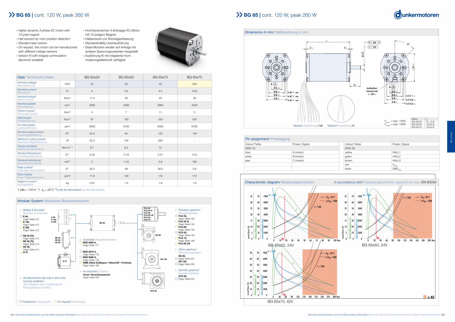
ϑR = 20°C
ΔϑW = 100K
ϑR = 20°C
ΔϑW = 100K
ϑR = 20°C
ΔϑW = 100K
Characteristic diagram / Belastungskennlinien In accordance with EN 60034 Belastungskennlinien gezeichnet nach EN 60034
BG 65x50, 24V
BG 65x75, 42V
BG 65x25, 24V
n = KI
Pin assignment / Pinbelegung (BG 65 Hall)Colour/Farbe Power Colour/Farbe SignalAWG 18 AWG 26blue A yellow HS1white B green HS2grey C brown HS3
red UHall
black GNDHall
Pin assignment / Pinbelegung (BG 65 KI)Colour/Farbe Powerred UPower
black GNDPower
4x Ø 3.7 -0.11
4x Ø 4.66 -0.11
4x Ø 4.66 -0.11
B
2 -0.3
L
2 -0.3
A
Ø 25 -0.04
Ø 36 ±0.1
Ø 40 ±0.1
Ø 48 ±0.1
4x M4 7-1 mm4x M5 7-1 mm4x M5 7-1 mm
25 ±1
Ø 8 -
0.011
-0.00
5
0.03
A0.06
Ø 25 -0.04
Ø 36 ±0.1
Ø 40 ±0.1
Ø 48 ±0.1
45°
65±0
.5
Anschlusslitzen/Connection Leads
L = 300 ±30
B
Ø 25Ø 25
Version / Ausführung KIVersion / Ausführung Hall
E 90 E 100 E 300 BG 65
Pin assignment/ Pinbelegung
Colour/ Farbe Power | Signal Colour/ Farbe Power | Signal
AWG 18 AWG 26
blue A (motor) yellow HALL1
white B (motor) green HALL2
grey C (motor) brown HALL3
red UHall
black GNDHall
Dimensions in mm/ Maßzeichnung in mm
BG 65x50, 24V
45°
Ø 48 ±0.1
A
Ø 25 -0.04
Ø 36 ±0.1
Ø 40 ±0.1
Ø 48 ±0.1
4x M4 7 -1 mm
4x M5 7 -1 mm
4x M5 7 -1 mm
2 -0.3
L
2 -0.3
25 ±1
Anschlusslitzen/Connection Leads
L = 300 ±30
-0.00
5
0.06 A
0.03
Ø 8 -
0.011
65±0
.5
4x Ø 3. 7 -0.11
4x Ø 4.66 -0.11
4x Ø 4.66 -0.11
Ø 40 ±0.1
Ø 36 ±0.1
B
Ø 25 -0.04
BG 65x25, 24V
Motor LBG 65x25 75 ±0.8BG 65x50 100±0.8BG 65x75 125±0.8
BG 65x75, 42V
BG 65 | cont. 120 W, peak 260 W
Faxial = max. 150NFradial = max. 150N
35
45°
Ø 48 ±0.1
A
Ø 25 -0.04
Ø 36 ±0.1
Ø 40 ±0.1
Ø 48 ±0.1
4x M4 7 -1 mm
4x M5 7 -1 mm
4x M5 7 -1 mm
2 -0.3
L
2 -0.3
25 ±1
Anschlusslitzen/Connection Leads
L = 300 ±30
-0.00
5
0.06 A
0.03
Ø 8 g
5 -0
.011
65±0
.5
4x Ø 3. 7 -0.11
4x Ø 4.66 -0.11
4x Ø 4.66 -0.11
Ø 40 ±0.1
Ø 36 ±0.1
B
Ø 25 -0.04
(
)
BG 65 / BG 65 KI, 50 - 150 W
Dimensions in mm / Maßzeichnung in mm
Motor L Hall L KIBG 65x25 75±0.8 90±0.8BG 65x50 100±0.8 115±0.8BG 65x75 125±0.8 140±0.8
Faxial = max. 150NFradial = max. 150N
0 10 20 30 40 50 60 70 80 90 100 Ncm
7000
6000
5000
4000
3000
2000
1000
0
70
60
50
40
30
20
10
0
35
30
25
20
15
10
5
0 rated
spee
d/Dr
ehza
hl n (
rpm)
effic
iency
/Wirk
ungs
grad
η (%
)
curre
nt/S
trom
I (A)
N = f (M)
J = f (M)
MN
η
0 20 40 60 80 100 120 140 160 180 200 Ncm
7000
6000
5000
4000
3000
2000
1000
0
70
60
50
40
30
20
10
0
35
30
25
20
15
10
5
0 rated
spee
d/Dr
ehza
hl n (
rpm)
effic
iency
/Wirk
ungs
grad
η (%
)
curre
nt/S
trom
I (A)
N = f (M)J = f (M)
MN
η
0 30 60 90 120 150 180 210 240 270 300 Ncm
7000
6000
5000
4000
3000
2000
1000
0
70
60
50
40
30
20
10
0
70
60
50
40
30
20
10
0 rated
spee
d/Dr
ehza
hl n (
rpm)
effic
iency
/Wirk
ungs
grad
η (%
)
curre
nt/S
trom
I(A)
MN
N = f (M)
J = f (M)η
ϑR = 20°C
ΔϑW = 100K
ϑR = 20°C
ΔϑW = 100K
ϑR = 20°C
ΔϑW = 100K
Characteristic diagram / Belastungskennlinien In accordance with EN 60034 Belastungskennlinien gezeichnet nach EN 60034
BG 65x50, 24V
BG 65x75, 42V
BG 65x25, 24V
n = KI
Pin assignment / Pinbelegung (BG 65 Hall)Colour/Farbe Power Colour/Farbe SignalAWG 18 AWG 26blue A yellow HS1white B green HS2grey C brown HS3
red UHall
black GNDHall
Pin assignment / Pinbelegung (BG 65 KI)Colour/Farbe Powerred UPower
black GNDPower
4x Ø 3.7 -0.11
4x Ø 4.66 -0.11
4x Ø 4.66 -0.11
B
2 -0.3
L
2 -0.3
A
Ø 25 -0.04
Ø 36 ±0.1
Ø 40 ±0.1
Ø 48 ±0.1
4x M4 7-1 mm4x M5 7-1 mm4x M5 7-1 mm
25 ±1
Ø 8 -
0.011
-0.00
5
0.03
A0.06
Ø 25 -0.04
Ø 36 ±0.1
Ø 40 ±0.1
Ø 48 ±0.1
45°
65±0
.5
Anschlusslitzen/Connection Leads
L = 300 ±30
B
Ø 25Ø 25
Version / Ausführung KIVersion / Ausführung Hall
35
45°
Ø 48 ±0.1
A
Ø 25 -0.04
Ø 36 ±0.1
Ø 40 ±0.1
Ø 48 ±0.1
4x M4 7 -1 mm
4x M5 7 -1 mm
4x M5 7 -1 mm
2 -0.3
L
2 -0.3
25 ±1
Anschlusslitzen/Connection Leads
L = 300 ±30
-0.00
5
0.06 A
0.03
Ø 8 g
5 -0
.011
65±0
.5
4x Ø 3. 7 -0.11
4x Ø 4.66 -0.11
4x Ø 4.66 -0.11
Ø 40 ±0.1
Ø 36 ±0.1
B
Ø 25 -0.04
(
)
BG 65 / BG 65 KI, 50 - 150 W
Dimensions in mm / Maßzeichnung in mm
Motor L Hall L KIBG 65x25 75±0.8 90±0.8BG 65x50 100±0.8 115±0.8BG 65x75 125±0.8 140±0.8
Faxial = max. 150NFradial = max. 150N
0 10 20 30 40 50 60 70 80 90 100 Ncm
7000
6000
5000
4000
3000
2000
1000
0
70
60
50
40
30
20
10
0
35
30
25
20
15
10
5
0 rated
spee
d/Dr
ehza
hl n (
rpm)
effic
iency
/Wirk
ungs
grad
η (%
)
curre
nt/S
trom
I (A)
N = f (M)
J = f (M)
MN
η
0 20 40 60 80 100 120 140 160 180 200 Ncm
7000
6000
5000
4000
3000
2000
1000
0
70
60
50
40
30
20
10
0
35
30
25
20
15
10
5
0 rated
spee
d/Dr
ehza
hl n (
rpm)
effic
iency
/Wirk
ungs
grad
η (%
)
curre
nt/S
trom
I (A)
N = f (M)J = f (M)
MN
η
0 30 60 90 120 150 180 210 240 270 300 Ncm
7000
6000
5000
4000
3000
2000
1000
0
70
60
50
40
30
20
10
0
70
60
50
40
30
20
10
0 rated
spee
d/Dr
ehza
hl n (
rpm)
effic
iency
/Wirk
ungs
grad
η (%
)
curre
nt/S
trom
I(A)
MN
N = f (M)
J = f (M)η
ϑR = 20°C
ΔϑW = 100K
ϑR = 20°C
ΔϑW = 100K
ϑR = 20°C
ΔϑW = 100K
Characteristic diagram / Belastungskennlinien In accordance with EN 60034 Belastungskennlinien gezeichnet nach EN 60034
BG 65x50, 24V
BG 65x75, 42V
BG 65x25, 24V
n = KI
Pin assignment / Pinbelegung (BG 65 Hall)Colour/Farbe Power Colour/Farbe SignalAWG 18 AWG 26blue A yellow HS1white B green HS2grey C brown HS3
red UHall
black GNDHall
Pin assignment / Pinbelegung (BG 65 KI)Colour/Farbe Powerred UPower
black GNDPower
4x Ø 3.7 -0.11
4x Ø 4.66 -0.11
4x Ø 4.66 -0.11
B
2 -0.3
L
2 -0.3
A
Ø 25 -0.04
Ø 36 ±0.1
Ø 40 ±0.1
Ø 48 ±0.1
4x M4 7-1 mm4x M5 7-1 mm4x M5 7-1 mm
25 ±1
Ø 8 -
0.011
-0.00
5
0.03
A0.06
Ø 25 -0.04
Ø 36 ±0.1
Ø 40 ±0.1
Ø 48 ±0.1
45°
65±0
.5
Anschlusslitzen/Connection Leads
L = 300 ±30
B
Ø 25Ø 25
Version / Ausführung KIVersion / Ausführung Hall Version/ Ausführung KIVersion/ Ausführung Hall
» All attachments also fully in the motor housing availbale./ Alle Anbauten auch vollständig im Motorgehäuse erhältlich.
Characteristic diagram/ Belastungskennlinien In accordance with/ Belastungskennlinien gezeichnet nach EN 60034
Preference/ Vorzugsreihe On request/ auf Anfrage
BG
mot
ors
STG 65
R 37