TECHNICAL SPECIFICATION FOR DETAIL SURVEY OF … Const. Division... · TECHNICAL SPECIFICATION FOR...
45
CDJ-228 GPS SURVEY TENDER PART-II.doc Page 1 of 42 Signature of Bidder GUJARAT ENERGY TRANSMISSION CORPORATION LIMITED CONSTRUCTION DIVISION JAMBUVA. TECHNICAL SPECIFICATION FOR DETAIL SURVEY OF VARIOUS 220/66KV TRANSMISSION LINES USING MODERN SURVEY TECHNIQUES UNDER JAMBUVA CONSTRUCTION DIVISION (PART-II)
Transcript of TECHNICAL SPECIFICATION FOR DETAIL SURVEY OF … Const. Division... · TECHNICAL SPECIFICATION FOR...

CDJ-228 GPS SURVEY TENDER PART-II.doc Page 1 of
42
Signature of Bidder
GUJARAT ENERGY TRANSMISSION CORPORATION LIMITED
CONSTRUCTION DIVISION
JAMBUVA.
TECHNICAL SPECIFICATION FOR
DETAIL SURVEY OF
VARIOUS 220/66KV TRANSMISSION LINES
USING MODERN SURVEY TECHNIQUES
UNDER JAMBUVA CONSTRUCTION DIVISION
(PART-II)
CDJ-228 GPS SURVEY TENDER PART-II.doc Page 2 of
42
Signature of Bidder
CDJ/ 228
CDJ-228 GPS SURVEY TENDER PART-II.doc Page 3 of
42
Signature of Bidder
INDEX
Clause No. Description Page No. 1.0 Detail of Transmission Line. 4
2.0 Scope of work 4 3.0 Route Alignment 5 4.0 Detailed Survey 7 5.0 Geotechnical Investigation 12 6.0 Statutory Requirement and
Standards 28
Annexure - A
General description of Towers & Foundation & Technical Parameter
29
Annexure – B
Document to be submitted along the bid
36
Annexure- C List of Outputs 37
CDJ-228 GPS SURVEY TENDER PART-II.doc Page 4 of
42
Signature of Bidder
TECHNICAL SPECIFICATIONS FOR SURVEY
CDJ-228 GPS SURVEY TENDER PART-II.doc Page 5 of
42
Signature of Bidder
1.0 General information:- The technical specification covers detailed survey including route alignment, profiling, Tower spotting, contouring and soil investigation etc. 2.0 Scope of work : The scope of work interalia shall include the following: a) Route alignment using satellite imageries of NRSA and Survey of India Maps, interalia
including :- i) Identification of three alternative route alignments & selection of optimized route
alignment. This shall be done using low resolution satellite imageries of NRSA and Survey of India Maps. The output shall be in the form of digitized route alignment drawing with latest topographical and other details / features upto 8 kms on both sides of selected route alignment.
ii) Digital terrain modeling along the selected route using contour data from topographical maps.
b) Detailed survey using GPS, Total work stations, long range scanners & Digital theodolites of reasonable accuracies or alternatively using ALTM (Airborne Laser Terrain Modeling) techniques, interalia including : i) Digitised profiling along the selected route along with plan details using PLS CADD. ii) Computer aided tower spotting & optimization iii) Soil resistivity measurement along the route at interval of every 3 Km. iv) Digitized contouring at undulated / hilly tower locations. v) Trial pit of Size- 1 Meter x 1Meter x 3 Meter at every 3 Km or as per the instruction of
engineer In charge and measurement of records of soil strata and submission of the same with proposed type of foundation and back filling.
c) Soil Investigation d) Preparation of survey reports including estimation of Bill of Quantities tower foundation and
line material, identification and explanation of route constraints, infrastructure details available enroute etc.
e) Training to GETCO engineers for implementation of software. 2.1 The owner reserves the right to split the total work and award the work for different
transmission lines mentioned above to more than one bidder without any change in terms & conditions as applicable for the complete work.
2.2 The Provisional quantities for the scope of work are indicated in relevant Part- III. The final quantities for route alignment & detailed survey (quantities in ‘kms’ unit) shall be the route length along the approved route alignment. For contouring at undulated / hilly tower locations and soil investigations (quantities in ‘locations’ unit), the actual quantities to be executed shall be decided by Site Engineer-in-charge. The route alignment, detailed survey, including profiling & tower spotting, contouring, soil investigation etc. shall be carried out by the Contractor as per the technical specifications stipulated here in.
2.3 The contractor must note that the Owner shall not be responsible for loss or damage to properties, trees etc due to contractor’s work during survey. The contractor shall indemnity the Owner for any loss or damage to properties, trees etc during the survey work.
2.4 The contractor should note Owner will not furnish the NRSA satellite imageries or topographical maps prepared by survey of India but will make available assistance that may be required in obtaining these by providing letters of recommendation to the concerned authorities. Further, in case the contractor opts for use of ALTM techniques for detailed
CDJ-228 GPS SURVEY TENDER PART-II.doc Page 6 of
42
Signature of Bidder
survey, he shall be responsible for obtaining necessary clearances / permissions by providing letters or recommendations to the concerned authorities.
2.5 All the bidders shall present their proposal methodology for execution of the work as per specifications and details of the equipment & facilities including softwares available with them within 21 days from date of invitation of bid, based on which the Owner may issue suitable amendments. A pre-bid conference shall also be held within 30 days from date of invitation of bid.
2.6 The work shall be carried out by the contractor using modern surveying techniques. The bidder shall indicate in his offer, the detailed description of the procedure to be deployed. The details of the equipment & facilities including softwares for image processing, computer aided tower spotting etc. available with the bidder or his associates shall also be furnished with the bid.
2.7 The contractor shall also engage services of a reputed geo-technical consultant or experts from independent educational / research institutions for examining stability aspects of the selected transmission line route / locations in hilly terrain and ualacreble wherever required.
2.8 After carrying out the detailed survey and soil investigations, the contractor shall submit documents as per Annexure- B.
2.9 Location Details 2.10 No Technical deviation whatsoever to certain conditions of the bidding documents
permitted by the Owner and therefore, the Bidders are advised that while making Bid Proposals and quoting prices these conditions may appropriately be taken into consideration.
The Bidder shall complete all the schedules & annexure in the Bid Proposal Sheets, Technical Data Sheets and specified elsewhere. This specification covers the detailing, of survey of 400/220 KV Transmission line and handing over to GETCO including a complete Data 2.11 The above transmission lines are in the State of Gujarat. Bidders may visit the site to
acquaint themselves with the terrain etc. For this purpose, they are requested to contact at the following address :
Executive Engineer (Projects), Gujarat Energy Transmission Corporation Ltd., Construction Division, National Highway No:8 Opp. Jambuva Vilage. Jambuva. VADODARA-390014 Telephone No.: 0265 – 2644406 Fax No.: 0265 – 2640119 3.0 Route Alignment : 3.1 Route alignment shall be done using satellite imageries of NRSA (PAN & LISS-III merged
product of minimum resolution corresponding to 1:25,000 scale) and survey of India topographical maps (scale 1:50,000). In case the required Survey of India, maps are available in digitized form from Survey of India, the same shall be procured and used by the Contractor. The contractor shall identify & examine three alternative route alignments and suggest to the Owner the optimal route alignment between the terminal points.
CDJ-228 GPS SURVEY TENDER PART-II.doc Page 7 of
42
Signature of Bidder
3.2 Requirement of Transmission Line Routing 3.2.1 The alignment of the transmission line shall be most economical from the point of view
of construction and maintenance. 3.2.2 Routing of transmission line through protected / reserved forest area should be avoided.
In case it is not possible to avoid the forests or areas having large trees completely, then keeping in view of the overall economy, the route should be aligned in such a way that cutting of trees is minimum.
3.2.3 The route should have minimum crossings of Major river, Railway lines, National / State highways, overhead EHV power line and communication lines.
3.2.4 The number of angle points shall be kept to a minimum. 3.2.5 The distance between the terminal points specified shall be kept shortest possible,
consistent with the terrain that is encountered. 3.2.6 Marshy and low lying areas, river beds and earth slip zones shall be avoided to
minimize risk to the foundations. & Towers 3.2.7 It would be preferable to utilize level ground for the alignment. 3.2.8 Crossing of power lines shall be minimum. Alignment will be kept at a minimum distance
of 300 m from power lines to avoid induction problems on the lower voltage lines. 3.2.9 Crossing of communication line shall be minimized and it shall be preferably at right
angle. Proximity and parallelism with telecom lines shall be eliminated to avoid danger of induction to them.
3.2.10 Areas subjected to flooding such as nalla shall be avoided. 3.2.11 Restricted areas such as civil and military airfield shall be avoided. Care shall also be
taken to avoid aircraft landing approaches. 3.2.12 All alignment should be easily accessible both in dry and rainy seasons to enable
maintenance throughout the year. 3.2.13 Certain areas such as quarry sites, tea, tobacco and saffron fields and rich plantations,
gardens & nurseries which will present the Owner problems in acquisition of right of way and way leave clearance during construction and maintenance should be avoided.
3.2.14 Angle points should be selected such that shifting of the point within 100 m radius is possible at the time of construction of the line.
3.2.15 The line routing should avoid large habitations, densely populated areas to the extent possible.
3.2.16 The areas requiring special foundations and those prone to flooding should be avoided. 3.3 For examination of the alternatives & identification of the most appropriate route, besides
making use of informations / data / details available / extracted through Survey of India Topographical maps and computer aided processing of NRSA’s satellite imagery, the contractor shall also carry out reconnaissance / preliminary survey as may be required for verification & collection of additional informations / data / details.
3.4 The contractor shall submit his preliminary observations & suggestions along with various
informations / data / details collected and also processed satellite imagery data, topographical map data marked with the alternative routes etc. The final evaluation of the alternative routes shall be conducted by the contractor in consultation with Owner’s representatives and optimal route alignment shall be proposed by the Contractor. Digital terrain modeling using contour data from topographical maps as well as processed satellite data shall be done by the contractor for the selected route. A fly through perspective using suitable software(s) shall be developed for further refinement of the selected route, if
CDJ-228 GPS SURVEY TENDER PART-II.doc Page 8 of
42
Signature of Bidder
required. Site visit and field verification shall be conducted by the contractor jointly with the Owner’s representative for the proposed route alignment.
3.5 Final digitized route alignment drawing with latest topographical and other detail / features
(altitude / longitude) including all rivers, railway lines, canals, roads etc upto 8 kms on both sides of selected routé alignment shall be submitted by the contractor for Owner’s approval along with report containing other informations / details as mentioned above.
4.0 Detailed Survey : 4.1 The detailed walk over survey shall be carried out using GPS, total stations, digital theodolites etc. along the approved route alignment. As an alternative, the contractor may also use ALTM (Airborne Laser Terrain Modeling) techniques of equal or better accuracy for the detailed survey and plotting on topo sheet to fix up angle point. . 4.1 Soil resistivity, along the route alignment shall be measured in dry weather by four
electrode method keeping inter – electrode spacing of 50 mtrs. For calculating soil resistivity formula 2πar (where a=50 m and r=megger reading in ohms) shall be adopted. In case of soil characteristics changes within 2 to 3 km, values shall have to be measured at intermediate locations also. Megger reading and soil characteristics should also be indicated in the soil resistivity results.
4.2 Route Marking
The route of the transmission line shall be recorded using GPS of positional accuracy less than 3m. The co-ordinates of all the angle points as well as other important crossings, landmarks etc. shall be recorded using GPS for easy relocating. At the starting point of the commencement of route survey the co-ordinates shall be recoded. The co-ordinates of the location of the survey instrument shall also be recorded. Further, the co-ordinates at prominent position at intervals of not more than 750 meter along the transmission line to be surveyed upto the next angle point shall also be recorded. Wherever the line alignment crosses the EHT line, Railway line, P&T line or roads, the contractor shall record co-ordinates on the points of crossing. Wherever line route alignment passes over permanent land marks such as rock, boulders, culverts etc. suitable white paint marks with directional and GETCO markings shall be made and co-ordinates recorded.
4.3 Profiling 4.3.1 The complete profiling along the route shall be carried out using surveying equipments
viz. total stations, GPS, digital theodolite, long range scanners etc. Reference levels at every 20 meters along the route are to be recorded. R/Ls at other undulations along the route as well as in the route plan and other enroute details viz. crossings, building & structures, trees & other infrastructure etc shall also be recorded. Areas along the route, which in the view of the contractor, are not suitable for tower spotting, shall also be marked.
4.3.2 The complete profiling details shall be digitized and the data shall be prepared & stored in the format compatible to computer – aided tower spotting software.
4.3.3 A printed / plotted output of the digitized profiling shall be submitted by the contractor to Owner’s site-in-charge for review before taking up computer- aided tower spotting.
CDJ-228 GPS SURVEY TENDER PART-II.doc Page 9 of
42
Signature of Bidder
4.4 Optimization of tower location / tower spotting : 4.4.1 Optimization of tower locations shall be done by the Contractor using computer-aided
tower spotting software ( PLS CADD). In order to verify the results of computer aided tower spotting, the contractor shall supply the Owner, one licensed copy of tower spotting & optimization software(s) and shall also furnish sample calculations and manual tower spotting drawings for some typical sections.
4.4.2 The sag-tension characteristics of the conductor as well as tower spotting data is furnished in Annexure- A . Sag template curves, if any required for tower spotting shall be prepared by the contractor on acrylic sheet indicating cold curve, hot curve, ground clearance curve and support footing curve.
4.4.3 General description of towers is enclosed at Annexure – A for information of the Bidders.
4.4.4 Tower Spotting While profiling & spotting the towers, the following shall to be borne in mind :
(a) Span The number of consecutive spans between the section points shall not exceed 12 spans or 4.5 km in plain terrain and 10 spans or 3 km in hilly terrain for 220KV line. A section point shall comprise of tension point with minimum angle of deviation type towers as applicable.
(b) Extension / Truncation
An individual span shall be as near to the normal design span as possible. In case an individual span becomes too short with normal supports on account of undulations in ground profile, one or both the supports of the span may be extended by inserting standard body / leg extension. In case of locations where the ground clearance is available, truncated towers may be spotted. The provision kept in the design of towers with respect to body/leg extensions, truncations shall be intimated to the contractor by the Owner during execution stage. Indicative sketch of tower configuration depicting possible body / leg extensions, truncation provisions is enclosed at Annexure – A.
(c) Loading
There shall not be any upward force on suspension towers under normal working conditions and the suspension towers shall support at least the minimum weight span as provided in the designs. In case uplift is unavoidable, it shall be examined if the same can be overcome by adding standard body extensions to the towers failing which tension towers designed for the purpose shall be employed at such positions.
(d) Road Crossing
At all important road crossings, the tower shall be fitted with double suspension or tension insulator strings depending on the type of tower but the ground clearance at the roads under maximum temperature and in still air shall be such that even with conductor broken an adjacent span, ground clearance of the conductor from the road surfaces will not be less than 7.015Mtr for 220KV line. At all national highways tension towers shall be utilised and crossing span shall not be more than 250 meters.
(e) Railway Crossings
All the railway crossings coming enroute the transmission line shall be identified by the contractor. At the time of detailed survey, the railway crossings shall be finalized as per the regulation laid down by the Railway Authorities. The following are the important features of the prevailing regulations (revised in 1987).
CDJ-228 GPS SURVEY TENDER PART-II.doc Page 10 of
42
Signature of Bidder
i) The crossing shall be supported on large angle Y/D type tower on either side depending on the merits of each case.
ii) The crossing shall normally be at right angle to the railway track. iii) The minimum distance of the crossing tower shall be at least equal to the height of
the tower plus 6 meters away measured from the centre of the nearest railway track. iv) No crossing shall be located over a booster transformer, traction switching station,
traction sub-station or a track cabin location in an electrified area. v) Minimum ground clearance above rail level of the lowest portion of any conductor
under condition of maximum sag shall be maintained at 15.40 Mtr for 220KV line. And14.6Mtr for 66KV line.
vi) The crossing span will be limited to 80% of Normal Span or 250 meters which ever is less.
(f) River Crossings
In case of major river crossings, towers shall be of suspension type and the anchor towers on either side of the main river crossing shall be large angle Y/ D type tower. Clearance required by navigation authority shall be provided. For non navigable river, clearance shall be reckoned with respect to highest flood level (HFL). Minimum ground clearance above the highest flood level river and lowest point of conductor shall be 5.1 Mtr. for 220KV line.
(g) Power line crossings
Where this line is to cross over another line of the same voltage or lower voltage, R / A type tower with suitable extensions shall be used. Provisions to prevent the possibility of its coming into contact with other overhead lines shall be made in accordance with the Indian Electricity Rules, 1956 / Indian Electricity Act, 2003 as amended upto date. In order to reduce the height of the crossings towers it may be advantageous to remove the ground-wire of the line to be crossed (if this is possible, and permitted by the owner of the line to be crossed). Minimum clearance in meters between lines when crossing each other :
Sr. No.
Nominal system voltage 66 KV &132 KV
220 KV 400 KV
1. 66 KV &132 KV 4.58 4.58 5.49 2. 220 KV 4.58 4.58 5.49 3. 400 KV 5.49 5.49 5.49
For power line crossings of voltage level of 132 KV and above, an angle towers shall be
provided on either side of tangent R /A type tower which can be temporary dead end condition with proper guying.
(h) Telecommunication Line Crossings
The angle of crossing shall be as near to 90 degree possible. However, deviation to the extent of 30 degree may be permitted under exceptionally difficult situations. When the angle of crossing has to be below 60 degree, the matter will be referred to the authority incharge of the telecommunication system. On a request from the contractor, the permission of the telecommunication authority may be obtained by the owner. Also, in the crossing span, power line support will be as near the telecommunication line as possible, to obtain increased vertical clearance between the wires.
CDJ-228 GPS SURVEY TENDER PART-II.doc Page 11 of
42
Signature of Bidder
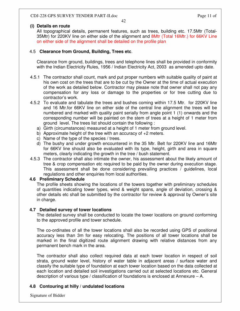
(i) Details en route All topographical details, permanent features, such as trees, building etc. 17.5Mtr (Total- 35Mtr) for 220KV line on either side of the alignment and 8Mtr (Total 16Mtr.) for 66KV Line on either side of the alignment shall be detailed on the profile plan
4.5 Clearance from Ground, Building, Trees etc.
Clearance from ground, buildings, trees and telephone lines shall be provided in conformity with the Indian Electricity Rules, 1956 / Indian Electricity Act, 2003 as amended upto date.
4.5.1 The contractor shall count, mark and put proper numbers with suitable quality of paint at
his own cost on the trees that are to be cut by the Owner at the time of actual execution of the work as detailed below. Contractor may please note that owner shall not pay any compensation for any loss or damage to the properties or for tree cutting due to contractor’s work.
4.5.2 To evaluate and tabulate the trees and bushes coming within 17.5 Mtr. for 220KV line and 16 Mtr.for 66KV line on either side of the central line alignment the trees will be numbered and marked with quality paint serially from angle point 1 (1) onwards and the corresponding number will be painted on the stem of trees at a height of 1 meter from ground level. The trees list should contain the following :
a) Girth (circumstances) measured at a height of 1 meter from ground level. b) Approximate height of the tree with an accuracy of +2 meters. c) Name of the type of the species / trees. d) The bushy and under growth encountered in the 35 Mtr. Belt for 220KV line and 16Mtr
for 66KV line should also be evaluated with its type, height, girth and area in square meters, clearly indicating the growth in the tree / bush statement.
4.5.3 The contractor shall also intimate the owner, his assessment about the likely amount of tree & crop compensation etc required to be paid by the owner during execution stage. This assessment shall be done considering prevailing practices / guidelines, local regulations and other enquiries from local authorities.
4.6 Preliminary Schedule The profile sheets showing the locations of the towers together with preliminary schedules of quantities indicating tower types, wind & weight spans, angle of deviation, crossing & other details etc shall be submitted by the contractor for review & approval by Owner’s site in charge.
4.7 Detailed survey of tower locations
The detailed survey shall be conducted to locate the tower locations on ground conforming to the approved profile and tower schedule. The co-ordinates of all the tower locations shall also be recorded using GPS of positional accuracy less than 3m for easy relocating. The positions of all tower locations shall be marked in the final digitized route alignment drawing with relative distances from any permanent bench mark in the area. The contractor shall also collect required data at each tower location in respect of soil strata, ground water level, history of water table in adjacent areas / surface water and classify the suitable type of foundation at each tower location based on the data collected at each location and detailed soil investigations carried out at selected locations etc. General description of various type / classification of foundations is enclosed at Annexure – A.
4.8 Contouring at hilly / undulated locations
CDJ-228 GPS SURVEY TENDER PART-II.doc Page 12 of
42
Signature of Bidder
The levels up or down of each pit centre with respect to centre of tower location shall be recorded at intervals of 2m using total stations / GPS / digital theodolite and digitized contour plans shall be made. Based on the digitized elevation plans, the quantities of benching & protection work vis-à-vis possible unequal leg extensions shall be optimized using suitable computer aided techniques / softwares. Required tower and foundation details, cost data for comparative evaluation of benching & protection work vis-à-vis unequal leg extension shall be provided by the owner to the contractor during execution stage.
4.9 The changes desired by the owner in the preliminary tower schedule or as may be
required based on detailed survey of tower locations & contouring by the contractor, shall be carried out by the contractor and the final tower schedule shall be submitted for approval of owner. The tower schedule shall show position of all type of towers, span length, type of foundation for each tower, benching & revetment requirement, unequal leg extensions, deviation at all angles, crossings & other details etc.
4.10 Survey Methodology & Precision
All elevations shall be referenced to benchmarks established by the survey of India. Leveling operations shall begin and end at benchmarks approved by the Owner. During the leveling of the profile, check surveys will be effected at intervals not exceeding 50 kms. with benchmarks of known elevations. The difference in elevations as surveyed by the contractor and as declared by survey of India for these benchmarks shall not exceed the precision required for 3rd order surveys e≤24k where k is the distance between benchmarks in km and e is the difference between elevations in mm. In the absence of suitable benchmarks the leveling shall be done by two independent leveling parties working in opposite directions along the same line. The difference in elevations between the two surveys shall not exceed the precision required for 3rd order surveys as stated above. All important objects and features along the transmission line centerline (railways, highways, roads, canals, rivers, transmission lines, distribution lines, telephone lines etc) shall be surveyed and located with a positional accuracy of 1:2000 between points of known horizontal position.
4.11 Survey Report List of output please refer Annexure – C.
CDJ-228 GPS SURVEY TENDER PART-II.doc Page 13 of
42
Signature of Bidder
5.0 GEOTECHNICAL INVESTIGATIONS 5.1 General 5.1.1 Owner requires that a detailed Geotechnical investigation be carried out at various tower
locations to provide the designer with sufficiently accurate information, both general and specific, about the substrata profile and relevant soil and rock parameters at site on the basis of which the foundation of transmission line towers can be classified and designed rationally.
5.1.2 These specifications provide general guidelines for geotechnical investigation of normal soils. Cases of marshy locations and these affected by salt water or saltpeter shall be treated as special locations and the corresponding description in these specifications shall apply. Any other information required for such locations shall be obtained by contractor and furnished to owner.
5.2 Scope 5.2.1 The scope of work includes detail soil investigations and furnishing bore log data at
various tower locations. The provisional quantities have been indicated in Bill of Quantities. However, during actual execution of work, the quantities shall be decided by Engineer – in – Charge, depending upon the soil strata and terrain. Based on the bore log data / soil parameter / soil investigation results, the contractor shall recommend the type of foundations suitable for each locations and the same shall be got approved by the owner.
5.2.2 These specifications cover the technical requirement for a detailed Geotechnical investigation and submission of a detailed Geotechnical Report. The work shall include mobilization of all necessary tools and equipment, provision of necessary engineering supervision and technical personnel, skilled and unskilled labour, etc. as required to carry out the entire field investigation as well as laboratory tests, analysis and interpretations of data collected and preparation of the Geotechnical Report. Contractor shall also collect data regarding variation of subsoil water table along the proposed line route. The aforementioned work shall be supervised by a graduate in Civil Engineering having at least 5 years of site experience in geotechnical investigation work.
5.2.3 Contractor shall make his own arrangements to establish the co-ordinate system required to position boreholes, tests pits and other field test locations as per the drawings / sketches supplied by Owner. Contractor shall determine the reduced levels (RL’s) at these locations with respect to benchmarks used in the detailed survey. Two reference lines shall be established based on survey data / details. Contractor shall provide at site all required survey instruments to the satisfactions of the owner so that the work can be carried out accurately according to specifications and drawings. Contractor shall arrange to collect the data regarding change of course of rivers, major natural streams and nalas etc., encountered along the transmission line route from the best available sources and shall furnish complete hydrological details including maximum velocity discharge, highest flood level (H.F.L), scour depth etc. of the concerned rivers, major streams and nalas (canals).

CDJ-228 GPS SURVEY TENDER PART-II.doc Page 14 of
42
Signature of Bidder
5.2.4 The field and laboratory data shall be recorded on the proforma recommended in relevant Indian Standards. Contractor shall submit to owner two copies of filed bore logs (one copy each to owner site and corporate office) and all the field records (countersigned by the owner) soon after the completion of each boreholes / test.
5.2.5 Whenever contractor is unable to extract undisturbed samples, he shall immediately inform the owner. Payment for boring charges shall be subject to owner being satisfied that adequate effort has been made to extract undisturbed samples. Special care shall be taken for locations where marshy soils are encountered and contractor in such cases shall ensure that specified number of vane shear tests are performed and the results correlated with other soil parameters.
5.2.6 One copy of all field records and laboratory test results shall be sent to owner on a weekly basis. Owner may observe, all the laboratory testing procedures.
5.2.7 The contractor shall interact with the owner to get acquainted with the different types of structures envisaged and in assessing the load intensities on the foundation for the various types of towers in order to enable him to make specific recommendation for the depth, founding strata, type of foundation and the allowable bearing pressure.
5.2.8 After reviewing contractor’s geotechnical investigation draft report, owner will call for discussions, to be held normally within one week at owners site office, in order to comment on the report in the presence of contractor’s Geotechnical Engineer. All expenditure associated with the redrafting and finalizing the report, traveling etc. shall be deemed included in the rates quoted for the geotechnical investigations.
5.2.9 Contractor shall carry out all work expressed and implied in clause no. 4.1.2 of these specifications in accordance with requirements of the specification.
5.2.10 The contractor shall prepare and submit soil profile along the transmission line route (in digitized form, with digitized route alignment drawing as base) indicating salient soil characteristics / features, water table etc. based on detailed soil investigations and other details / information collected during detailed survey.
5.3 General Requirements 5.3.1 Wherever possible, contractor shall research and review existing local knowledge,
records of test pits, boreholes etc., types of foundations adopted and the behavior of exiting structures, particularly those similar to the present project.
5.3.2 Contractor shall make use of information gathered from nearby quarries, unlined wells, excavation etc. study of the general topography of the surrounding areas will often help in the delineation of different soil types.
5.3.3 Contractor shall gather data regarding the removal of overburden in the project area either by performing test excavations, or by observing soil erosion or land slides in order to estimate reconsolidation of the soil strata. Similarly, data regarding recent land fills shall be studied to detennine the characteristics of such land fills as well as the original soil strata.
5.3.4 The water level in neighboring streams and water courses shall be noted. Contractor shall make enquiries and shall verify whether there are abandoned under ground works e.g. worked out ballast pits, quarries, old brick fields, mines, mineral workings etc.
5.3.5 It is essential that equipment and instruments be properly calibrated at the commencement of the work. If the owner so desires. Contractor shall arrange for having the instruments tested at an approved laboratory at their cost and shall submit the test reports to the owner. If the owner desires to witness such tests, contractor shall arrange for the same.
5.4 Codes and standards for Geotechnical Investigations
CDJ-228 GPS SURVEY TENDER PART-II.doc Page 15 of
42
Signature of Bidder
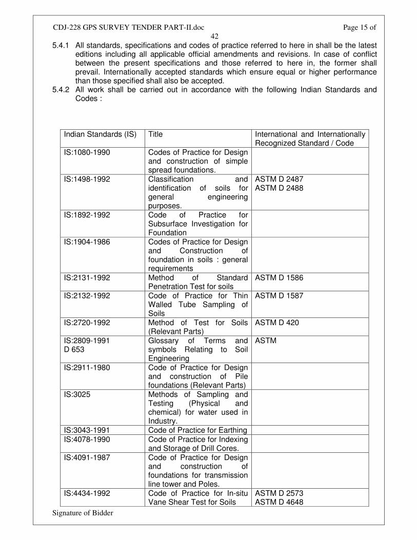
5.4.1 All standards, specifications and codes of practice referred to here in shall be the latest editions including all applicable official amendments and revisions. In case of conflict between the present specifications and those referred to here in, the former shall prevail. Internationally accepted standards which ensure equal or higher performance than those specified shall also be accepted.
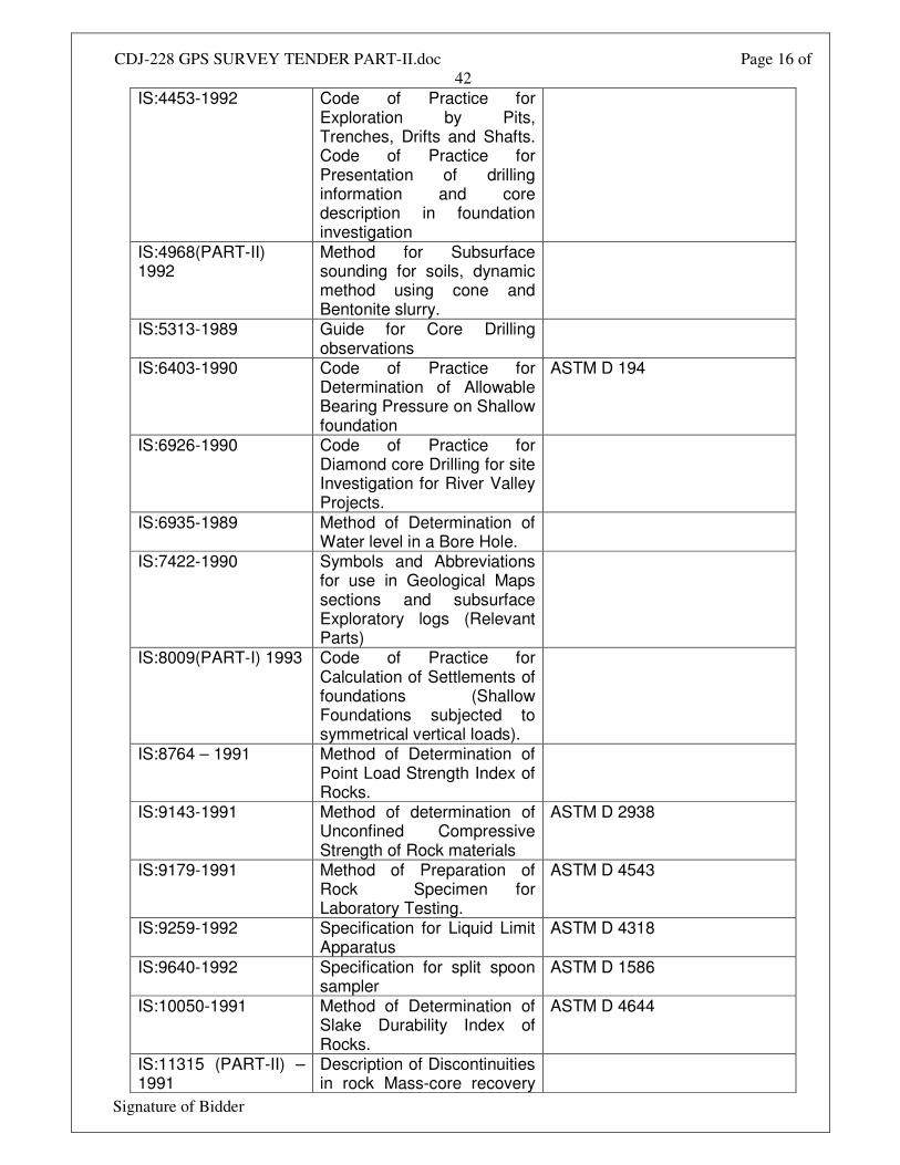
5.4.2 All work shall be carried out in accordance with the following Indian Standards and Codes :
Indian Standards (IS) Title International and Internationally Recognized Standard / Code
IS:1080-1990 Codes of Practice for Design and construction of simple spread foundations.
IS:1498-1992 Classification and identification of soils for general engineering purposes.
ASTM D 2487 ASTM D 2488
IS:1892-1992 Code of Practice for Subsurface Investigation for Foundation
IS:1904-1986 Codes of Practice for Design and Construction of foundation in soils : general requirements
IS:2131-1992 Method of Standard Penetration Test for soils
ASTM D 1586
IS:2132-1992 Code of Practice for Thin Walled Tube Sampling of Soils
ASTM D 1587
IS:2720-1992 Method of Test for Soils (Relevant Parts)
ASTM D 420
IS:2809-1991 D 653
Glossary of Terms and symbols Relating to Soil Engineering
ASTM
IS:2911-1980 Code of Practice for Design and construction of Pile foundations (Relevant Parts)
IS:3025 Methods of Sampling and Testing (Physical and chemical) for water used in Industry.
IS:3043-1991 Code of Practice for Earthing IS:4078-1990 Code of Practice for Indexing
and Storage of Drill Cores.
IS:4091-1987 Code of Practice for Design and construction of foundations for transmission line tower and Poles.
IS:4434-1992 Code of Practice for In-situ Vane Shear Test for Soils
ASTM D 2573 ASTM D 4648
CDJ-228 GPS SURVEY TENDER PART-II.doc Page 16 of
42
Signature of Bidder
IS:4453-1992 Code of Practice for Exploration by Pits, Trenches, Drifts and Shafts. Code of Practice for Presentation of drilling information and core description in foundation investigation
IS:4968(PART-II) 1992
Method for Subsurface sounding for soils, dynamic method using cone and Bentonite slurry.
IS:5313-1989 Guide for Core Drilling observations
IS:6403-1990 Code of Practice for Determination of Allowable Bearing Pressure on Shallow foundation
ASTM D 194
IS:6926-1990 Code of Practice for Diamond core Drilling for site Investigation for River Valley Projects.
IS:6935-1989 Method of Determination of Water level in a Bore Hole.
IS:7422-1990 Symbols and Abbreviations for use in Geological Maps sections and subsurface Exploratory logs (Relevant Parts)
IS:8009(PART-I) 1993 Code of Practice for Calculation of Settlements of foundations (Shallow Foundations subjected to symmetrical vertical loads).
IS:8764 – 1991 Method of Determination of Point Load Strength Index of Rocks.
IS:9143-1991 Method of determination of Unconfined Compressive Strength of Rock materials
ASTM D 2938
IS:9179-1991 Method of Preparation of Rock Specimen for Laboratory Testing.
ASTM D 4543
IS:9259-1992 Specification for Liquid Limit Apparatus
ASTM D 4318
IS:9640-1992 Specification for split spoon sampler
ASTM D 1586
IS:10050-1991 Method of Determination of Slake Durability Index of Rocks.
ASTM D 4644
IS:11315 (PART-II) – 1991
Description of Discontinuities in rock Mass-core recovery
CDJ-228 GPS SURVEY TENDER PART-II.doc Page 17 of
42
Signature of Bidder
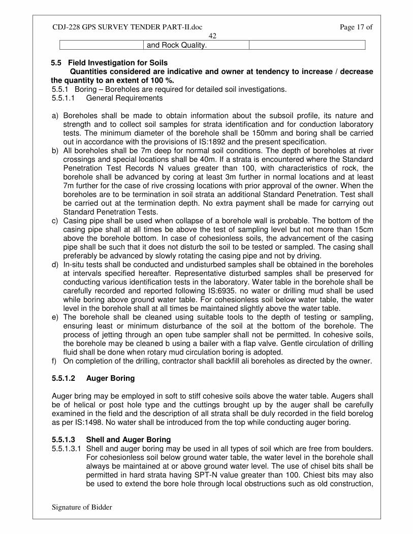
and Rock Quality. 5.5 Field Investigation for Soils Quantities considered are indicative and owner at tendency to increase / decrease the quantity to an extent of 100 %. 5.5.1 Boring – Boreholes are required for detailed soil investigations. 5.5.1.1 General Requirements a) Boreholes shall be made to obtain information about the subsoil profile, its nature and
strength and to collect soil samples for strata identification and for conduction laboratory tests. The minimum diameter of the borehole shall be 150mm and boring shall be carried out in accordance with the provisions of IS:1892 and the present specification.
b) All boreholes shall be 7m deep for normal soil conditions. The depth of boreholes at river crossings and special locations shall be 40m. If a strata is encountered where the Standard Penetration Test Records N values greater than 100, with characteristics of rock, the borehole shall be advanced by coring at least 3m further in normal locations and at least 7m further for the case of rive crossing locations with prior approval of the owner. When the boreholes are to be termination in soil strata an additional Standard Penetration. Test shall be carried out at the termination depth. No extra payment shall be made for carrying out Standard Penetration Tests.
c) Casing pipe shall be used when collapse of a borehole wall is probable. The bottom of the casing pipe shall at all times be above the test of sampling level but not more than 15cm above the borehole bottom. In case of cohesionless soils, the advancement of the casing pipe shall be such that it does not disturb the soil to be tested or sampled. The casing shall preferably be advanced by slowly rotating the casing pipe and not by driving.
d) In-situ tests shall be conducted and undisturbed samples shall be obtained in the boreholes at intervals specified hereafter. Representative disturbed samples shall be preserved for conducting various identification tests in the laboratory. Water table in the borehole shall be carefully recorded and reported following IS:6935. no water or drilling mud shall be used while boring above ground water table. For cohesionless soil below water table, the water level in the borehole shall at all times be maintained slightly above the water table.
e) The borehole shall be cleaned using suitable tools to the depth of testing or sampling, ensuring least or minimum disturbance of the soil at the bottom of the borehole. The process of jetting through an open tube sampler shall not be permitted. In cohesive soils, the borehole may be cleaned b using a bailer with a flap valve. Gentle circulation of drilling fluid shall be done when rotary mud circulation boring is adopted.
f) On completion of the drilling, contractor shall backfill ali boreholes as directed by the owner. 5.5.1.2 Auger Boring Auger bring may be employed in soft to stiff cohesive soils above the water table. Augers shall be of helical or post hole type and the cuttings brought up by the auger shall be carefully examined in the field and the description of all strata shall be duly recorded in the field borelog as per IS:1498. No water shall be introduced from the top while conducting auger boring. 5.5.1.3 Shell and Auger Boring 5.5.1.3.1 Shell and auger boring may be used in all types of soil which are free from boulders.
For cohesionless soil below ground water table, the water level in the borehole shall always be maintained at or above ground water level. The use of chisel bits shall be permitted in hard strata having SPT-N value greater than 100. Chiest bits may also be used to extend the bore hole through local obstructions such as old construction,
CDJ-228 GPS SURVEY TENDER PART-II.doc Page 18 of
42
Signature of Bidder
boulders rocky formations etc. the requirements in Clause 5.5.1.2 shall apply for this type of boring also. Rotary method may be used in all types of soil below water table. In this method the boring is carried out by rotating the bit fixed at the lower end of the drill rod. Proper care shall be taken to maintain firm contact between the bit and the bottom of the borehole. Bentonite or drilling mud shall be used as drillings fluid to stabilize and protect the inside surface of the borehole. Use of percussion tools shall be permitted in hard clays and in dense sandy deposits.
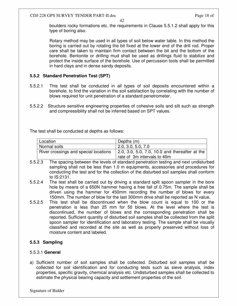
5.5.2 Standard Penetration Test (SPT) 5.5.2.1 This test shall be conducted in all types of soil deposits encountered within a
borehole, to find the variation in the soil satisfaction by correlating with the number of blows required for unit penetration of a standard penetrometer.
5.5.2.2 Structure sensitive engineering properties of cohesive soils and silt such as strength
and compressibility shall not be inferred based on SPT values. The test shall be conducted at depths as follows:
Location Depths (m) Normal soils 2.0, 3.0, 5.0, 7.0 River crossings and special locations 2.0, 3.0, 5.0, 7.0, 10.0 and thereafter at the
rate of 3m intervals to 40m 5.5.2.3 The spacing between the levels of standard penetration testing and next undisturbed
sampling shall not be less than 1.0 m equipments, accessories and procedures for conducting the test and for the collection of the disturbed soil samples shall conform to IS:2131.
5.5.2.4 The test shall be carried out by driving a standard split spoon sampler in the bore hole by means of a 650N hammer having a free fall of 0.75m. The sample shall be driven using the hammer for 450mm recording the number of blows for every 150mm. The number of blow for the last 300mm drive shall be reported as N value.
5.5.2.5 This test shall be discontinued when the blow count is equal to 100 or the penetration is less than 25 mm for 50 blows. At the level where the test is discontinued, the number of blows and the corresponding penetration shall be reported. Sufficient quantity of disturbed soil samples shall be collected from the split spoon sampler for identification and laboratory testing. The sample shall be visually classified and recorded at the site as well as properly preserved without loss of moisture content and labeled.
5.5.3 Sampling 5.5.3.1 General a) Sufficient number of soil samples shall be collected. Disturbed soil samples shall be
collected for soil identification and for conducting tests such as sieve analysis, index properties, specific gravity, chemical analysis etc. Undisturbed samples shall be collected to estimate the physical bearing capacity and settlement properties of the soil.
CDJ-228 GPS SURVEY TENDER PART-II.doc Page 19 of
42
Signature of Bidder
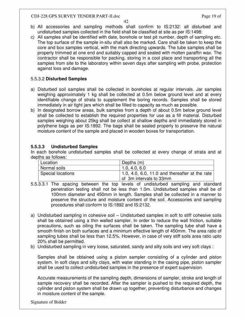
b) All accessories and sampling methods shall confirm to IS:2132: all disturbed and undisturbed samples collected in the field shall be classified at site as per IS:1498:
c) All samples shall be identified with date, borehole or test pit number, depth of sampling etc. The top surface of the sample in-situ shall also be marked. Care shall be taken to keep the core and box samples vertical, with the mark directing upwards. The tube samples shall be properly trimmed at one end and suitably capped and sealed with molten paraffin wax. The contractor shall be responsible for packing, storing in a cool place and transporting all the samples from site to the laboratory within seven days after sampling with probe, protection against loss and damage.
5.5.3.2 Disturbed Samples a) Disturbed soil samples shall be collected in boreholes at regular intervals. Jar samples
weighing approximately 1 kg shall be collected at 0.5m below ground level and at every identifiable change of strata to supplement the boring records. Samples shall be stored immediately in air tight jars which shall be filled to capacity as much as possible.
b) In designated borrow areas, bulk samples from a depth of about 0.5m below ground level shall be collected to establish the required properties for use as a fill material. Disturbed samples weighing about 25kg shall be collect at shallow depths and immediately stored in polythene bags as per IS:1892. The bags shall be sealed properly to preserve the natural moisture content of the sample and placed in wooden boxes for transportation.
5.5.3.3 Undisturbed Samples In each borehole undisturbed samples shall be collected at every change of strata and at depths as follows:
Location Depths (m) Normal soils 1.0, 4.0, 6.0 Special locations 1.0, 4.0, 6.0, 11.0 and thereafter at the rate
of 3m intervals to 33mm 5.5.3.3.1 The spacing between the top levels of undisturbed sampling and standard
penetration testing shall not be less than 1.0m. Undisturbed samples shall be of 100mm diameter and 450mm in length. Samples shall be collected in a manner to preserve the structure and moisture content of the soil. Accessories and sampling procedures shall conform to IS:1892 and IS:2132.
a) Undisturbed sampling in cohesive soil – Undisturbed samples in soft to stiff cohesive soils
shall be obtained using a thin walled sampler. In order to reduce the wall friction, suitable precautions, such as oiling the surfaces shall be taken. The sampling tube shall have a smooth finish on both surfaces and a minimum effective length of 450mm. The area ratio of sampling tubes shall be less than 12.5%. However, in case of very stiff soils area ratio upto 20% shall be permitted.
b) Undisturbed sampling in very loose, saturated, sandy and silty soils and very soft clays : Samples shall be obtained using a piston sampler consisting of a cylinder and piston system. In soft clays and silty clays, with water standing in the casing pipe, piston sampler shall be used to collect undisturbed samples in the presence of expert supervision. Accurate measurements of the sampling depth, dimensions of sampler, stroke and length of sample recovery shall be recorded. After the sampler is pushed to the required depth, the cylinder and piston system shall be drawn up together, preventing disturbance and changes in moisture content of the sample.
CDJ-228 GPS SURVEY TENDER PART-II.doc Page 20 of
42
Signature of Bidder
c) Undisturbed sampling in cohesionless soils Undisturbed samples in cohesionless soils shall be obtained in accordance with IS:8763. Sampler operated by compressed air shall be used to sample cohesionless soils below ground water table.
5.5.4 Ground Water 5.5.4.1 One of the following methods shall be adopted for determining the elevation of ground water table in boreholes as per IS:6935 and the instructions of the Owner:
a) In permeable soils, the water level in the borehole shall be allowed to stabilize after depressing it adequately by bailing before recording its level. Stability of sides and bottom of the boreholes shall be ensured at all times.
b) For both permeable and impermeable soils, the following method shall be suitable. The borehole shall be filled with water and then bailed out to various depths. Observations on the raise or fall of water nor rise is observed shall be considered the water table elevation and confirmed by three successive readings of water level taken at two hours interval.
5.5.4.2 If any variation of the ground water level is observed in any specific boreholes, the
water level in these boreholes shall be recorded during the course of the field investigation. Levels in nearby wells, streams, etc. if any, shall also be noted in parallel.
5.5.4.3 Subsoil water samples (only at special locations) a) Sub soil water samples shall be collected for performing chemical analysis.
Representative ground water samples shall be collected when first encountered in boreholes and before the addition of water to aid boring or drilling.
b) Chemical analysis of water samples shall include determination of pH value, turbidity, sulphate, carbonate, nitrate and chloride contents, presence of organic matter and suspended solids. Chemical preservatives may be added to the sample for cases as specified in the test methods or in applicable Indian Standards. This shall only be done if analysis can not be conducted within an hour of collection and shall have the prior written permission and approval of the Owner.
5.5.5 Dynamic Cone Penetration Test (only at Special locations) Dynamic cone penetration test shall be conducted to predict stratification, density, bearing capacity of granular soils etc. The test shall be conducted to the specified depth or refusal, whichever comes first. Refusal shall be recorded when the blow count exceeds 150 for 300 mm penetration. Equipment, accessories test procedures, field observations and reporting of results shall confirm to IS:4968, Part-II. The driving system shall comprise of a 650 kg weight having a free fall of 0.75m. The cone shall be of 65mm diameter provide with vents for continuous flow of bentonite slurry through the cone and rods in order to avoid friction between the rods and soil. On completion of the test the results shall be presented as a continuous record of the number of blows required for every 300 mm penetration of the cone into the soil in a suitable chart supplemented by a graphical plot of blow count for 300 mm penetration vs. depth. On completion of the test, the results shall be presented on the proforma approved by the Owner.
CDJ-228 GPS SURVEY TENDER PART-II.doc Page 21 of
42
Signature of Bidder
5.5.6 Vane Shear Test - required for boreholes where UDS is not possible (Only at Special Locations)
Field vane shear test shall be performed inside the borehole to determine the shear strength and bearing capacity of cohesive soils. Equipment, accessories, test procedures, field observations shall correspond to IS:4434. Tests may also be conducted by direct penetration from ground surface. If the cuttings at the test depth in the borehole show any presence of gravel, sand shells, decomposed wood, etc. which are likely to influence the test results substantially, the test at that particular depth may be omitted with the permission of the owner. However, the test shall be conducted at depth where these obstructions cease to occur. On completion of the test, the results shall be reported in an approved proforma as specified in IS:4434, Appendix-A. 5.6 Field Investigation for Rock 5.6.1 Rock Drilling 5.6.1.1 If, during the investigations, large hard fragments or natural rock beds are encountered, work shall proceed with core drilling methods. The equipment and procedures for this operation shall confirm to IS:1892. The starting depth of drilling in rock shall be certified by the owner. At the end of the investigation, the hole drilled in rock shall be backfilled with grout consisting of 1 part cement and 3 parts sand by weight. 5.6.1.2 Drilling shall be carried out with NX size tungsten carbide (TC) or diamond tipped drill bits, depending on the type of rock and according to IS:6926. Suitable type of drill bit (TC/Diamond) and core catchers shall be used to ensure continuous and good core recovery. Core barrels and core catchers shall be used for breaking off the core and retaining it when the rods are withdrawn. Double tube core barrels shall be used to ensure better core recovery and to retrieve cores from layers of bedrock. Water shall be circulated continuously in the hollow rods and the sludge conveying the rock cuttings to the surface shall be collected. A very high core recovery ratio shall be aimed at in order to obtain a satisfactory undisturbed sample. Attempt shall be made to recover cores of 1.5m length. Normally TC bit shall be used. Change over to a diamond bit shall require the specific written approval of the owner and his decision as to whether a TC or a diamond bit is to be used shall be final and binding on contractor. 5.6.1.3 No drilling run shall exceed 1.5m in depth. If the core recovery is less than 80% in any run, the length of the subsequent run shall be reduced to 0.75m. During drilling operations observations on return water, rate of penetration etc. shall be made recorded and recorded as per IS:5313. a) The colour of return water at regular intervals, the depth at which any change of colour of
return water is observed, the depth of occurrence and amount of flow of hot water, if encountered, shall be recorded.
b) The depth through which a uniform rate of penetration was maintained, the depth at which marked change in rate of penetration or sudden fall on drill rod occurs, the depth at which any blockage of drill bit causing core loss, if any, shall be recorded.
c) Any heavy vibration or torque noticed during the drilling should be recorded together with the depth of occurrence.
d) Special conditions like the depth at which grouting was done during drilling, presence of artesian conditions, loss of drilling fluid observations of gas discharge with return water etc. shall also be observed and recorded.
CDJ-228 GPS SURVEY TENDER PART-II.doc Page 22 of
42
Signature of Bidder
e) All the observations and other details shall be recorded as per daily drill and reported in a proforma as given in IS:5313, Appendix A.
5.6.2 Core Sampling 5.6.2.1 Core samples shall be extracted by the application of a continuous pressure at one end of the core with the barrel held horizontally without vibration. Friable cores shall be extracted from the barrel directly into a suitably sized half round plastic channel section. Care shall be taken to extrude the samples in the direction of coring to avoid stress reversal. 5.6.2.2 Immediately after withdrawal from the core barrel, the cores shall be placed in a tray and transferred to boxes specially prepared for this purpose. The boxes shall be made from seasoned timber or any other durably material and shall be indexed on top pf the lid according to IS:4078. The cores shall be numbered serially and arranged in the boxes in a sequential order. The description of the core samples shall be recorded as instructed in IS:4464. Where no core is recovered, it shall be recorded as specified in the standard. Continuous record of core recovery and rock quality designation (RQD) are to be mentioned in the borelog in accordance with IS:1 1315 (Part-II). 5.7 Laboratory Testing 5.7.1 Essential Requirements a) Depending on the types of substrata encountered, appropriate laboratory tests shall be
conducted on soil and rock samples collected in the field. Laboratory tests shall be scheduled and performed by qualified and experienced personnel who are thoroughly conversant with the work. Tests indicated in the schedule of items shall be performed on soil, water and rock samples as per relevant IS codes. One copy of all laboratory test data records shall be submitted to Owner progressively ever week. Laboratory tests shall be carried out concurrently with the field investigations as initial laboratory test results could be useful in planning the later stages of field work. A schedule of laboratory tests shall be established by contractor to the satisfaction of the owner within one week of completion of the first bore hole.
b) Laboratory tests shall be conducted using approved apparatus complying with the requirements and specification of Indian Standards or other approved standards for this type of work. It shall be checked that the apparatus are in good working condition before starting the laboratory tests. Calibration of all the instruments and their accessories shall be done carefully and precisely at an approved laboratory.
c) All samples, whether undisturbed or disturbed shall be extracted, prepared and examined by competent personnel properly trained and experienced in soil sampling, examination, testing and in using the apparatus in conformance with the specified standards.
d) Undisturbed soil samples retained in liners or seamless tube samplers shall be removed, without causing any disturbance to the samples, using suitably designed extruders just prior to actual testing. If the extruder is horizontal, proper support shall be provided to prevent the sample from breaking. For screw tube extruders, the pushing head shall be free from the screw shaft so that no torque is applied to the soil sample in contact with the pushing head. For soft clay samples, the sample tube shall be cut by means of a high speed hacksaw to proper test length and placed over the mould before pushing the sample into it with a suitable piston.
e) While extracting a sample from a liner or tube, care shall be taken to assure that its direction of movement is the same as that during sampling to avoid stress reversal.
CDJ-228 GPS SURVEY TENDER PART-II.doc Page 23 of
42
Signature of Bidder
5.7.2 Tests 5.7.2.1 Tests as indicated in these specifications and as may be requested by the owner, shall be conducted. These tests shall include but may not be limited to the following : a) Tests of undisturbed and disturbed samples
- Visual and engineering classification - Sieve analysis and hydrometric analysis - Liquid, plastic and shrinkage limits - Specific gravity - Chemical analysis - Swell pressure and free swell index determination - Proctor compaction test
b) Tests of undisturbed samples - Bulk density and moisture content - Relative density (for sand) - Unconfined compression test - Box shear test (for sand) - Triaxial shear tests (depending on the type of soil and field conditions on undisturbed or
remoulded samples) - Unconsolidated undrained - Consolidated drained test - Consolidation
c) Tests on rock samples - Visual classification - Moisture content, porosity and density - Specific gravity - Hardness - Stake durability - Unconfined compression test (both saturated and at in-situ water content) - Point load strength index - Deformability test (both saturated and at in-situ water content)
d) Chemical analysis of sub soil water. 5.7.3 Salient Test Requirement a) Triaxial shear tests shall be conducted on undisturbed soil samples, saturated by the
application on back pressure. Only if the water table is at sufficient depth so that chances of its rising to the base of the footing are small or nil, the triaxial tests shall be performed on specimens at natural moisture content. Each test shall be carried out on as set of three test specimens from one sample at cell pressures equal to 100, 200 and 300 KPa respectively or as required depending on the soil conditions.
b) Direct shear test shall be conducted on undisturbed soil samples. The three normal vertical stresses for each test shall be 100, 200 and 300 KPa or as required for the soil conditions.
c) Consolidation test shall have loading stages of 10, 25, 50, 75, 100, 200, 400 and 800 KPa. Rebound curve shaft be recorded for all samples by unloading the specimen at its in-situ stress. Additional rebound curves shall also be recorded wherever desired by the owner.
d) Chemical analysis of subsoil shaft include determination of PH value, carbonate, sulphate (both SO3 and SO4), chloride and nitrate contents, organic matter, salinity and any other chemicals which ,may be harmful to the foundation material. The chemical contents shall be indicated as parts per million (PPM) based on weight.
CDJ-228 GPS SURVEY TENDER PART-II.doc Page 24 of
42
Signature of Bidder
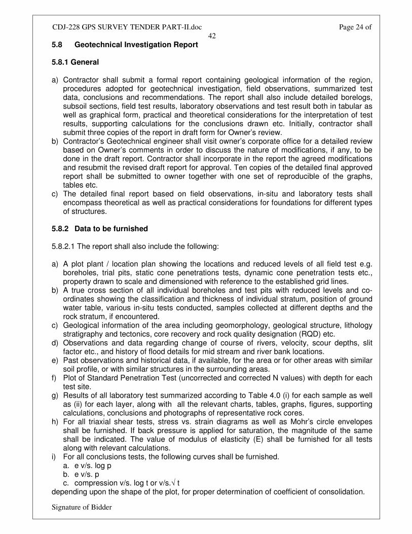
5.8 Geotechnical Investigation Report 5.8.1 General a) Contractor shall submit a formal report containing geological information of the region,
procedures adopted for geotechnical investigation, field observations, summarized test data, conclusions and recommendations. The report shall also include detailed borelogs, subsoil sections, field test results, laboratory observations and test result both in tabular as well as graphical form, practical and theoretical considerations for the interpretation of test results, supporting calculations for the conclusions drawn etc. Initially, contractor shall submit three copies of the report in draft form for Owner’s review.
b) Contractor’s Geotechnical engineer shall visit owner’s corporate office for a detailed review based on Owner’s comments in order to discuss the nature of modifications, if any, to be done in the draft report. Contractor shall incorporate in the report the agreed modifications and resubmit the revised draft report for approval. Ten copies of the detailed final approved report shall be submitted to owner together with one set of reproducible of the graphs, tables etc.
c) The detailed final report based on field observations, in-situ and laboratory tests shall encompass theoretical as well as practical considerations for foundations for different types of structures.
5.8.2 Data to be furnished 5.8.2.1 The report shall also include the following: a) A plot plant / location plan showing the locations and reduced levels of all field test e.g.
boreholes, trial pits, static cone penetrations tests, dynamic cone penetration tests etc., property drawn to scale and dimensioned with reference to the established grid lines.
b) A true cross section of all individual boreholes and test pits with reduced levels and co-ordinates showing the classification and thickness of individual stratum, position of ground water table, various in-situ tests conducted, samples collected at different depths and the rock stratum, if encountered.
c) Geological information of the area including geomorphology, geological structure, lithology stratigraphy and tectonics, core recovery and rock quality designation (RQD) etc.
d) Observations and data regarding change of course of rivers, velocity, scour depths, slit factor etc., and history of flood details for mid stream and river bank locations.
e) Past observations and historical data, if available, for the area or for other areas with similar soil profile, or with similar structures in the surrounding areas.
f) Plot of Standard Penetration Test (uncorrected and corrected N values) with depth for each test site.
g) Results of all laboratory test summarized according to Table 4.0 (i) for each sample as well as (ii) for each layer, along with all the relevant charts, tables, graphs, figures, supporting calculations, conclusions and photographs of representative rock cores.
h) For all triaxial shear tests, stress vs. strain diagrams as well as Mohr’s circle envelopes shall be furnished. If back pressure is applied for saturation, the magnitude of the same shall be indicated. The value of modulus of elasticity (E) shall be furnished for all tests along with relevant calculations.
i) For all conclusions tests, the following curves shall be furnished. a. e v/s. log p b. e v/s. p c. compression v/s. log t or v/s.√ t
depending upon the shape of the plot, for proper determination of coefficient of consolidation.
CDJ-228 GPS SURVEY TENDER PART-II.doc Page 25 of
42
Signature of Bidder
The point showing the initial condition (e0, p0) of the soil shall be marked on the curves. j) The procedure adopted for calculating the compression index from the field curve and
settlement of soil strata shall be clearly specified. The time required for 50% and 90% primary consolidation along with secondary settlements, if significant, shall also be calculated.
CDJ-228 GPS SURVEY TENDER PART-II.doc Page 26 of
42
Signature of Bidder
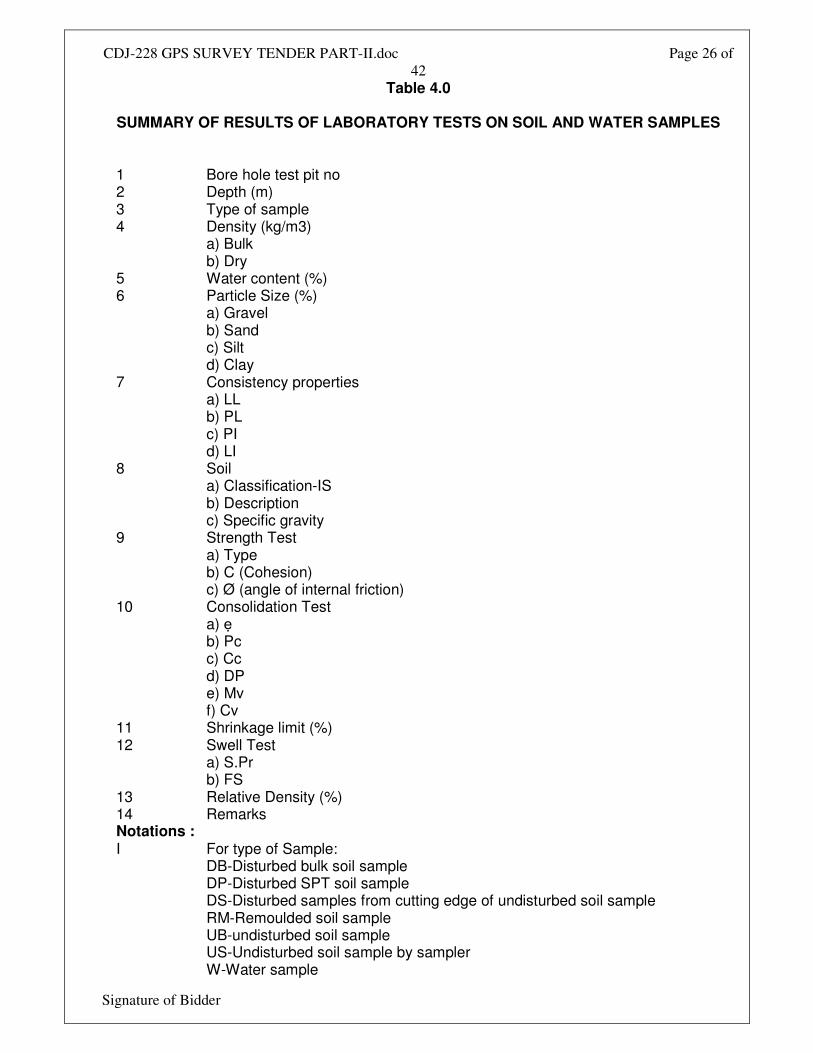
Table 4.0
SUMMARY OF RESULTS OF LABORATORY TESTS ON SOIL AND WATER SAMPLES
1 Bore hole test pit no 2 Depth (m) 3 Type of sample 4 Density (kg/m3) a) Bulk b) Dry 5 Water content (%) 6 Particle Size (%) a) Gravel b) Sand c) Silt d) Clay 7 Consistency properties a) LL b) PL c) PI d) LI 8 Soil a) Classification-IS b) Description c) Specific gravity 9 Strength Test a) Type b) C (Cohesion) c) Ø (angle of internal friction) 10 Consolidation Test a) ẹ b) Pc c) Cc d) DP e) Mv f) Cv 11 Shrinkage limit (%) 12 Swell Test a) S.Pr b) FS 13 Relative Density (%) 14 Remarks Notations : I For type of Sample: DB-Disturbed bulk soil sample DP-Disturbed SPT soil sample DS-Disturbed samples from cutting edge of undisturbed soil sample RM-Remoulded soil sample UB-undisturbed soil sample US-Undisturbed soil sample by sampler W-Water sample
CDJ-228 GPS SURVEY TENDER PART-II.doc Page 27 of
42
Signature of Bidder
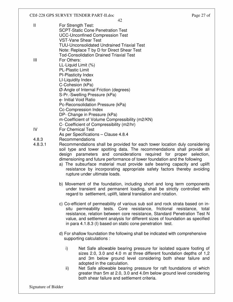
II For Strength Test: SCPT-Static Cone Penetration Test UCC-Unconfined Compression Test VST-Vane Shear Test TUU-Unconsolidated Undrained Triaxial Test Note: Replace T by D for Direct Shear Test Tod-Consolidation Drained Triaxial Test III For Others: LL-Liquid Limit (%) PL-Plastic Limit PI-Plasticity Index LI-Liquidity Index C-Cohesion (kPa) Ø-Angle of Internal Friction (degrees) S-Pr.-Swelling Pressure (kPa) ẹ- Initial Void Ratio Pc-Reconsolidation Pressure (kPa) Cc-Compression Index DP- Change in Pressure (kPa) m-Coefficient of Volume Compressibility (m2/KN) C- Coefficient of Compressibility (m2/hr) IV For Chemical Test As per Specifications – Clause 4.8.4 4.8.3 Recommendations 4.8.3.1 Recommendations shall be provided for each tower location duly considering
soil type and tower spotting data. The recommendations shall provide all design parameters and considerations required for proper selection, dimensioning and future performance of tower foundation and the following
a) The subsurface material must provide safe bearing capacity and uplift resistance by incorporating appropriate safety factors thereby avoiding rupture under ultimate loads.
b) Movement of the foundation, including short and long term components
under transient and permanent loading, shall be strictly controlled with regard to settlement, uplift, lateral translation and rotation.
c) Co-efficient of permeability of various sub soil and rock strata based on in-
situ permeability tests. Core resistance, frictional resistance, total resistance, relation between core resistance, Standard Penetration Test N value, and settlement analysis for different sizes of foundation as specified in para 4.1.8.3 (I) based on static cone penetration test.
d) For shallow foundation the following shall be indicated with comprehensive
supporting calculations :
i) Net Safe allowable bearing pressure for isolated square footing of sizes 2.0, 3.0 and 4.0 m at three different foundation depths of 1,2 and 3m below ground level considering both shear failure and adopted in the calculation.
ii) Net Safe allowable bearing pressure for raft foundations of which greater than 5m at 2.0, 3.0 and 4.0m below ground level considering both shear failure and settlement criteria.
CDJ-228 GPS SURVEY TENDER PART-II.doc Page 28 of
42
Signature of Bidder
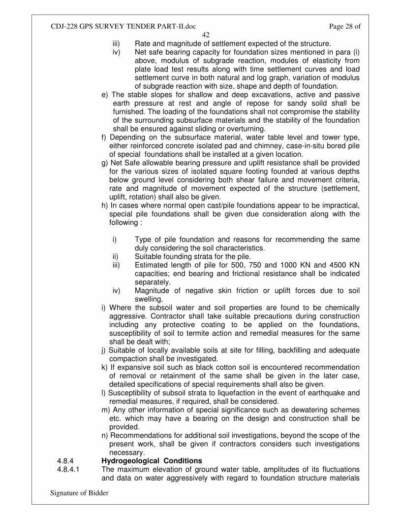
iii) Rate and magnitude of settlement expected of the structure. iv) Net safe bearing capacity for foundation sizes mentioned in para (i)
above, modulus of subgrade reaction, modules of elasticity from plate load test results along with time settlement curves and load settlement curve in both natural and log graph, variation of modulus of subgrade reaction with size, shape and depth of foundation.
e) The stable slopes for shallow and deep excavations, active and passive earth pressure at rest and angle of repose for sandy soild shall be furnished. The loading of the foundations shall not compromise the stability of the surrounding subsurface materials and the stability of the foundation shall be ensured against sliding or overturning.
f) Depending on the subsurface material, water table level and tower type, either reinforced concrete isolated pad and chimney, case-in-situ bored pile of special foundations shall be installed at a given location.
g) Net Safe allowable bearing pressure and uplift resistance shall be provided for the various sizes of isolated square footing founded at various depths below ground level considering both shear failure and movement criteria, rate and magnitude of movement expected of the structure (settlement, uplift, rotation) shall also be given.
h) In cases where normal open cast/pile foundations appear to be impractical, special pile foundations shall be given due consideration along with the following :
i) Type of pile foundation and reasons for recommending the same
duly considering the soil characteristics. ii) Suitable founding strata for the pile. iii) Estimated length of pile for 500, 750 and 1000 KN and 4500 KN
capacities; end bearing and frictional resistance shall be indicated separately.
iv) Magnitude of negative skin friction or uplift forces due to soil swelling.
i) Where the subsoil water and soil properties are found to be chemically aggressive. Contractor shall take suitable precautions during construction including any protective coating to be applied on the foundations, susceptibility of soil to termite action and remedial measures for the same shall be dealt with;
j) Suitable of locally available soils at site for filling, backfilling and adequate compaction shall be investigated.
k) If expansive soil such as black cotton soil is encountered recommendation of removal or retainment of the same shall be given in the later case, detailed specifications of special requirements shall also be given.
l) Susceptibility of subsoil strata to liquefaction in the event of earthquake and remedial measures, if required, shall be considered.
m) Any other information of special significance such as dewatering schemes etc. which may have a bearing on the design and construction shall be provided.
n) Recommendations for additional soil investigations, beyond the scope of the present work, shall be given if contractors considers such investigations necessary.
4.8.4 Hydrogeological Conditions 4.8.4.1 The maximum elevation of ground water table, amplitudes of its fluctuations
and data on water aggressively with regard to foundation structure materials
CDJ-228 GPS SURVEY TENDER PART-II.doc Page 29 of
42
Signature of Bidder
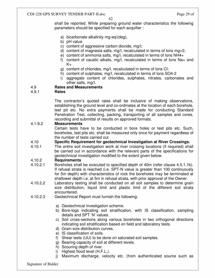
shall be reported. While preparing ground water characteristics the following parameters should be specified for each acquifier :
a) bicarbonate alkalinity mg-eq/(deg), b) pH value c) content of aggressive carbon dioxide, mg/I; d) content of magnesia salts, mg/I, recalculated in terms of lons mg+2; e) content of ammonia salts, mg/I, recalculated in terms of lons NH4+ f) content of caustic alkalis, mg/I, recalculated in terms of lons Na+ and
K+ g) content of chlorides, mg/I, recalculated in terms of lons CI- h) content of sulphates, mg/I, recalculated in terms of lons SO4-2 i) aggregate content of chlorides, sulphates, nitrates, carbonates and
other salts, mg/I. 4.9 Rates and Measurements 4.9.1 Rates
The contractor’s quoted rates shall be inclusive of making observations, establishing the ground level and co-ordinates at the location of each borehole, test pit etc. No extra payments shall be made for conducting Standard Penetration Test, collecting, packing, transporting of all samples and cores, recording and submittal of results on approved formats.
4.1.9.2 Measurements Certain tests have to be conducted in bore holes or test pits etc. Such, boreholes, test pits etc. shall be measured only once for payment regardless of the number of tests carried out
4.10 Specific Requirement for geotechnical Investigation at River Crossings. 4.10.1 The entire soil investigation work at river crossing locations (if required) shall
be carried out in accordance with the relevant parts of the specifications for geotechnical investigation modified to the extent given below.
4.10.2 Requirements 4.10.2.1 Boreholes shall be executed to specified depth of 40m (refer clause 4.5.1.1b).
If refusal strata is reached (i.e. SPT-N value is greater than 100 continuously for 5m depth) with characteristics of rock the boreholes may be terminated at shallower depth i.e. at 5m in refusal strata, with prior approval of the Owner.
4.10.2.2 Laboratory testing shall be conducted on all soil samples to determine grain size distribution, liquid limit and plastic limit of the different soil strata encountered.
4.10.2.3 Geotechnical Report must furnish the following: a) Geotechnical investigation scheme. b) Bore-logs indicating soil stratification, with IS classification, sampling
details and SPT ‘N’ values. c) Soil cross-sections along various boreholes in two orthogonal directions
indicating soil stratification based on field and laboratory tests. d) Grain size distribution curves. e) IS classification of soils. f) Shear tests (UU) to be done on saturated soil samples. g) Bearing capacity of soil at different levels. h) Scouring depth of river. i) Highest flood level (H.F.L.). j) Maximum discharge, velocity etc. (from authenticated source such as
CDJ-228 GPS SURVEY TENDER PART-II.doc Page 30 of
42
Signature of Bidder
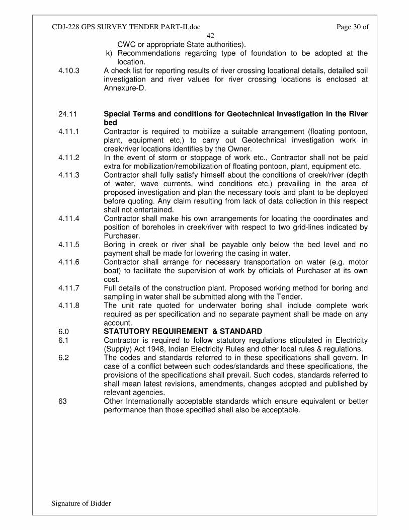
CWC or appropriate State authorities). k) Recommendations regarding type of foundation to be adopted at the
location. 4.10.3 A check list for reporting results of river crossing locational details, detailed soil
investigation and river values for river crossing locations is enclosed at Annexure-D.
24.11 Special Terms and conditions for Geotechnical Investigation in the River bed
4.11.1 Contractor is required to mobilize a suitable arrangement (floating pontoon, plant, equipment etc,) to carry out Geotechnical investigation work in creek/river locations identifies by the Owner.
4.11.2 In the event of storm or stoppage of work etc., Contractor shall not be paid extra for mobilization/remobilization of floating pontoon, plant, equipment etc.
4.11.3 Contractor shall fully satisfy himself about the conditions of creek/river (depth of water, wave currents, wind conditions etc.) prevailing in the area of proposed investigation and plan the necessary tools and plant to be deployed before quoting. Any claim resulting from lack of data collection in this respect shall not entertained.
4.11.4 Contractor shall make his own arrangements for locating the coordinates and position of boreholes in creek/river with respect to two grid-lines indicated by Purchaser.
4.11.5 Boring in creek or river shall be payable only below the bed level and no payment shall be made for lowering the casing in water.
4.11.6 Contractor shall arrange for necessary transportation on water (e.g. motor boat) to facilitate the supervision of work by officials of Purchaser at its own cost.
4.11.7 Full details of the construction plant. Proposed working method for boring and sampling in water shall be submitted along with the Tender.
4.11.8 The unit rate quoted for underwater boring shall include complete work required as per specification and no separate payment shall be made on any account.
6.0 STATUTORY REQUIREMENT & STANDARD 6.1 Contractor is required to follow statutory regulations stipulated in Electricity
(Supply) Act 1948, Indian Electricity Rules and other local rules & regulations. 6.2 The codes and standards referred to in these specifications shall govern. In
case of a conflict between such codes/standards and these specifications, the provisions of the specifications shall prevail. Such codes, standards referred to shall mean latest revisions, amendments, changes adopted and published by relevant agencies.
63 Other Internationally acceptable standards which ensure equivalent or better performance than those specified shall also be acceptable.
CDJ-228 GPS SURVEY TENDER PART-II.doc Page 31 of
42
Signature of Bidder
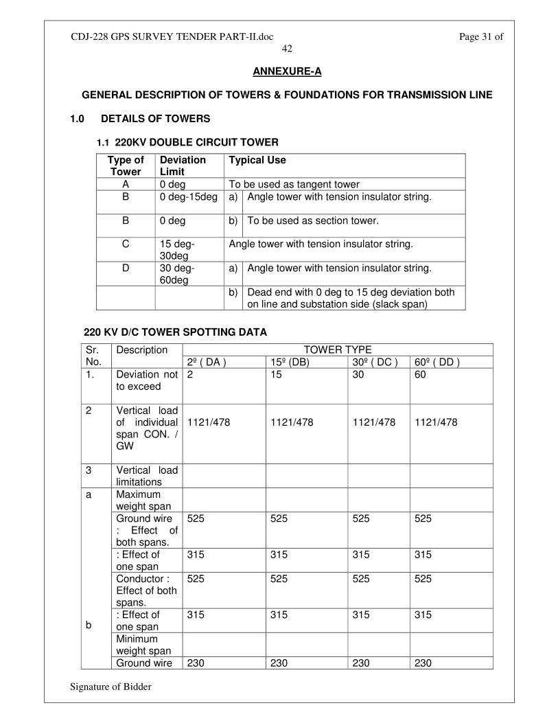
ANNEXURE-A
GENERAL DESCRIPTION OF TOWERS & FOUNDATIONS FOR TRANSMISSION LINE
1.0 DETAILS OF TOWERS
1.1 220KV DOUBLE CIRCUIT TOWER
Type of Tower
Deviation Limit
Typical Use
A 0 deg To be used as tangent tower B 0 deg-15deg a) Angle tower with tension insulator string.
B 0 deg b) To be used as section tower.
C 15 deg-30deg
Angle tower with tension insulator string.
D 30 deg-60deg
a) Angle tower with tension insulator string.
b) Dead end with 0 deg to 15 deg deviation both on line and substation side (slack span)
220 KV D/C TOWER SPOTTING DATA
TOWER TYPE Sr. No.
Description 2º ( DA ) 15º (DB) 30º ( DC ) 60º ( DD )
1. Deviation not to exceed
2 15 30 60
2 Vertical load of individual span CON. / GW
1121/478
1121/478
1121/478
1121/478
3 Vertical load limitations
Maximum weight span
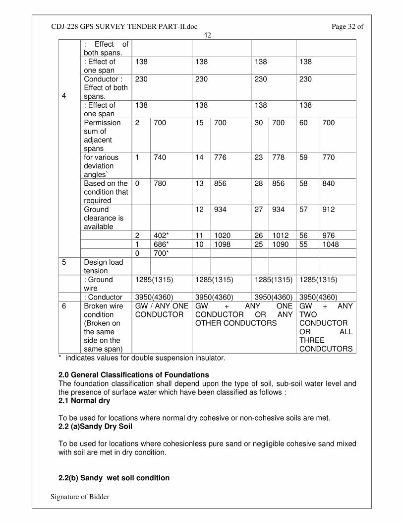
Ground wire : Effect of both spans.
525 525 525 525
: Effect of one span
315 315 315 315
Conductor : Effect of both spans.
525 525 525 525
: Effect of one span
315 315 315 315
Minimum weight span
a b Ground wire 230 230 230 230
CDJ-228 GPS SURVEY TENDER PART-II.doc Page 32 of
42
Signature of Bidder
: Effect of both spans. : Effect of one span
138 138 138 138
Conductor : Effect of both spans.
230 230 230 230
: Effect of one span
138 138 138 138
Permission sum of adjacent spans
2 700 15 700 30 700 60 700
for various deviation angles`
1 740 14 776 23 778 59 770
Based on the condition that required
0 780 13 856 28 856 58 840
Ground clearance is available
12 934 27 934 57 912
2 402* 11 1020 26 1012 56 976 1 686* 10 1098 25 1090 55 1048
4
0 700* 5 Design load
tension
: Ground wire
1285(1315) 1285(1315) 1285(1315) 1285(1315)
: Conductor 3950(4360) 3950(4360) 3950(4360) 3950(4360) 6 Broken wire
condition (Broken on the same side on the same span)
GW / ANY ONE CONDUCTOR
GW + ANY ONE CONDUCTOR OR ANY OTHER CONDUCTORS
GW + ANY TWO CONDUCTOR OR ALL THREE CONDCUTORS
* indicates values for double suspension insulator. 2.0 General Classifications of Foundations The foundation classification shall depend upon the type of soil, sub-soil water level and the presence of surface water which have been classified as follows : 2.1 Normal dry To be used for locations where normal dry cohesive or non-cohesive soils are met. 2.2 (a)Sandy Dry Soil To be used for locations where cohesionless pure sand or negligible cohesive sand mixed with soil are met in dry condition. 2.2(b) Sandy wet soil condition
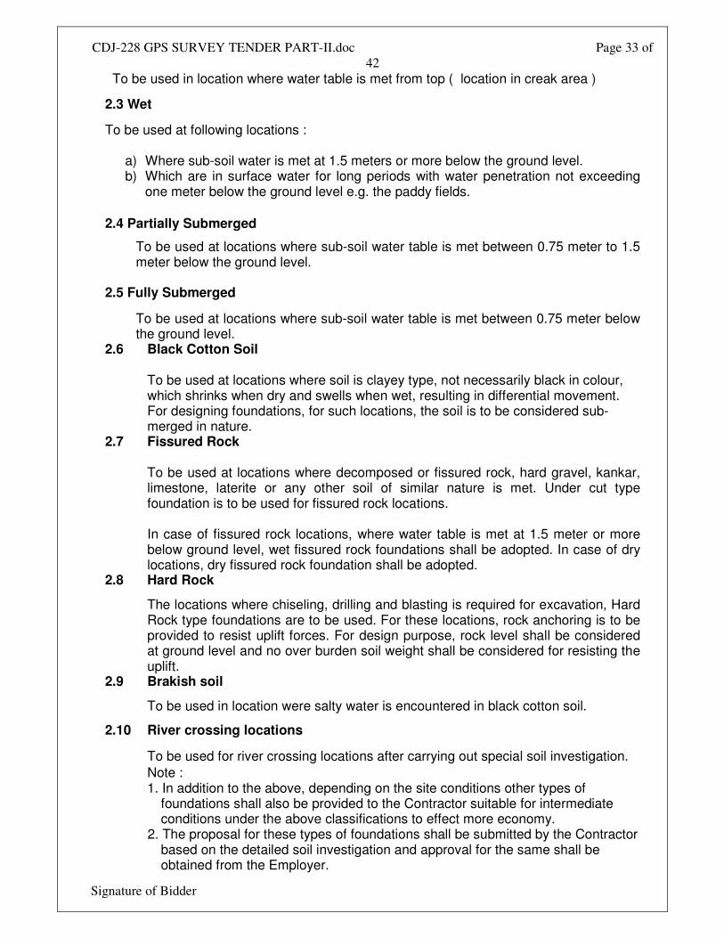
CDJ-228 GPS SURVEY TENDER PART-II.doc Page 33 of
42
Signature of Bidder
To be used in location where water table is met from top ( location in creak area )
2.3 Wet
To be used at following locations :
a) Where sub-soil water is met at 1.5 meters or more below the ground level. b) Which are in surface water for long periods with water penetration not exceeding
one meter below the ground level e.g. the paddy fields.
2.4 Partially Submerged
To be used at locations where sub-soil water table is met between 0.75 meter to 1.5 meter below the ground level.
2.5 Fully Submerged
To be used at locations where sub-soil water table is met between 0.75 meter below the ground level.
2.6 Black Cotton Soil To be used at locations where soil is clayey type, not necessarily black in colour, which shrinks when dry and swells when wet, resulting in differential movement. For designing foundations, for such locations, the soil is to be considered sub-merged in nature.
2.7 Fissured Rock To be used at locations where decomposed or fissured rock, hard gravel, kankar, limestone, laterite or any other soil of similar nature is met. Under cut type foundation is to be used for fissured rock locations. In case of fissured rock locations, where water table is met at 1.5 meter or more below ground level, wet fissured rock foundations shall be adopted. In case of dry locations, dry fissured rock foundation shall be adopted.
2.8 Hard Rock
The locations where chiseling, drilling and blasting is required for excavation, Hard Rock type foundations are to be used. For these locations, rock anchoring is to be provided to resist uplift forces. For design purpose, rock level shall be considered at ground level and no over burden soil weight shall be considered for resisting the uplift.
2.9 Brakish soil
To be used in location were salty water is encountered in black cotton soil.
2.10 River crossing locations
To be used for river crossing locations after carrying out special soil investigation.
Note : 1. In addition to the above, depending on the site conditions other types of
foundations shall also be provided to the Contractor suitable for intermediate conditions under the above classifications to effect more economy.
2. The proposal for these types of foundations shall be submitted by the Contractor based on the detailed soil investigation and approval for the same shall be obtained from the Employer.
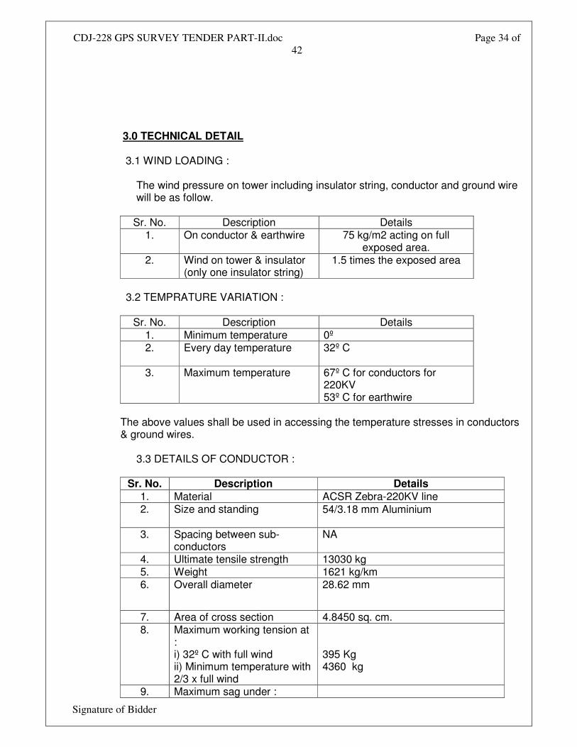
CDJ-228 GPS SURVEY TENDER PART-II.doc Page 34 of
42
Signature of Bidder
3.0 TECHNICAL DETAIL
3.1 WIND LOADING :
The wind pressure on tower including insulator string, conductor and ground wire will be as follow.
Sr. No. Description Details
1. On conductor & earthwire 75 kg/m2 acting on full exposed area.
2.
Wind on tower & insulator (only one insulator string)
1.5 times the exposed area
3.2 TEMPRATURE VARIATION :
Sr. No. Description Details 1. Minimum temperature 0º 2.
Every day temperature 32º C
3. Maximum temperature 67º C for conductors for 220KV 53º C for earthwire
The above values shall be used in accessing the temperature stresses in conductors & ground wires.
3.3 DETAILS OF CONDUCTOR :
Sr. No. Description Details
1. Material ACSR Zebra-220KV line 2.
Size and standing 54/3.18 mm Aluminium
3. Spacing between sub-conductors
NA
4. Ultimate tensile strength 13030 kg 5. Weight 1621 kg/km 6. Overall diameter 28.62 mm
7. Area of cross section 4.8450 sq. cm. 8. Maximum working tension at
: i) 32º C with full wind ii) Minimum temperature with 2/3 x full wind
395 Kg 4360 kg
9. Maximum sag under :
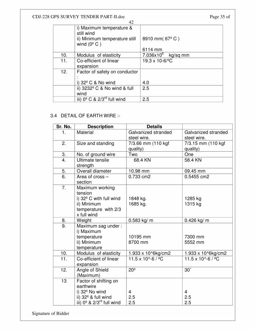
CDJ-228 GPS SURVEY TENDER PART-II.doc Page 35 of
42
Signature of Bidder
i) Maximum temperature & still wind ii) Minimum temperature still wind (0º C )
8910 mm( 67º C ) 6114 mm
10. Modulus of elasticity 7.036x10⁶ kg/sq mm 11. Co-efficient of linear
expansion 19.3 x 10⁻⁶/ºC
12. Factor of safety on conductor : i) 32º C & No wind
4.0
ii) 3232º C & No wind & full wind
2.5
iii) 0º C & 2/3rd full wind 2.5
3.4 DETAIL OF EARTH WIRE :-
Sr. No. Description Details
1. Material Galvanized stranded steel wire.
Galvanized stranded steel wire.
2.
Size and standing 7/3.66 mm (110 kgf quality)
7/3.15 mm (110 kgf quality)
3. No. of ground wire Two One 4. Ultimate tensile
strength 68.4 KN 58.4 KN
5. Overall diameter 10.98 mm 09.45 mm 6. Area of cross –
section 0.733 cm2 0.5455 cm2
7. Maximum working tension i) 32º C with full wind ii) Minimum temperature with 2/3 x full wind
1848 kg. 1685 kg.
1285 kg 1315 kg
8. Weight 0.583 kg/ m 0.426 kg/ m 9. Maximum sag under :
i) Maximum temperature ii) Minimum temperature
10195 mm 8700 mm
7300 mm 5552 mm
10. Modulus of elasticity 1.933 x 10^6kg/cm2 1.933 x 10^6kg/cm2 11. Co-efficient of linear
expansion 11.5 x 10^-6 / ºC 11.5 x 10^-6 / ºC
12. Angle of Shield (Maximum)
20º 30˚
13 Factor of shifting on earthwire i) 32º No wind ii) 32º & full wind iii) 0º & 2/3rd full wind
4 2.5 2.5
4 2.5 2.5
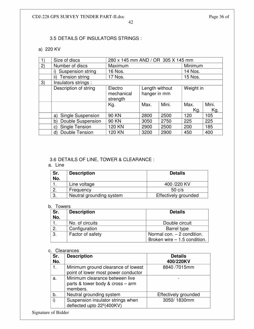
CDJ-228 GPS SURVEY TENDER PART-II.doc Page 36 of
42
Signature of Bidder
3.5 DETAILS OF INSULATORS STRINGS :
a) 220 KV
1) Size of discs 280 x 145 mm AND / OR 305 X 145 mm 2) Number of discs Maximum Minimum i) Suspension string 16 Nos. 14 Nos. ii) Tension string 17 Nos. 15 Nos. 3) Insulators strings : Description of string Electro
mechanical strength
Length without hanger in mm
Weight in
Kg. Max. Mini. Max. Kg.
Mini. Kg.
a) Single Suspension 90 KN 2800 2500 120 105 b) Double Suspension 90 KN 3050 2750 225 225 c) Single Tension 120 KN 2900 2500 200 185 d) Double Tension 120 KN 3200 2900 450 400
3.6 DETAILS OF LINE, TOWER & CLEARANCE :
a. Line
Sr. No.
Description Details
1. Line voltage 400 /220 KV 2. Frequency 50 c/s 3. Neutral grounding system Effectively grounded
b. Towers
Sr. No.
Description Details
1. No. of circuits Double circuit 2. Configuration Barrel type 3. Factor of safety Normal con. – 2 condition.
Broken wire – 1.5 condition. c. Clearances
Sr. No.
Description Details 400/220KV
1. Minimum ground clearance of lowest point of lower most power conductor
8840 /7015mm
a. Minimum clearance between live parts & tower body & cross – arm members.
-
b. Neutral grounding system Effectively grounded i) Suspension insulator strings when
deflected upto 22º(400KV) 3050/ 1830mm
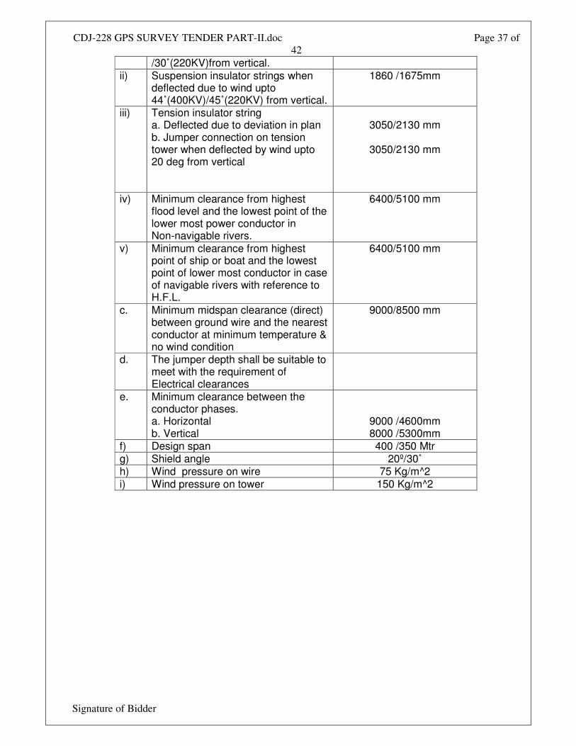
CDJ-228 GPS SURVEY TENDER PART-II.doc Page 37 of
42
Signature of Bidder
/30˚(220KV)from vertical. ii) Suspension insulator strings when
deflected due to wind upto 44˚(400KV)/45˚(220KV) from vertical.
1860 /1675mm
iii) Tension insulator string a. Deflected due to deviation in plan b. Jumper connection on tension tower when deflected by wind upto 20 deg from vertical
3050/2130 mm
3050/2130 mm
iv) Minimum clearance from highest flood level and the lowest point of the lower most power conductor in Non-navigable rivers.
6400/5100 mm
v) Minimum clearance from highest point of ship or boat and the lowest point of lower most conductor in case of navigable rivers with reference to H.F.L.
6400/5100 mm
c. Minimum midspan clearance (direct) between ground wire and the nearest conductor at minimum temperature & no wind condition
9000/8500 mm
d. The jumper depth shall be suitable to meet with the requirement of Electrical clearances
e. Minimum clearance between the conductor phases. a. Horizontal b. Vertical
9000 /4600mm 8000 /5300mm
f) Design span 400 /350 Mtr g) Shield angle 20º/30˚ h) Wind pressure on wire 75 Kg/m^2 i) Wind pressure on tower 150 Kg/m^2
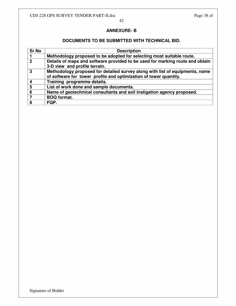
CDJ-228 GPS SURVEY TENDER PART-II.doc Page 38 of
42
Signature of Bidder
ANNEXURE- B
DOCUMENTS TO BE SUBMITTED WITH TECHNICAL BID.
Sr No Description 1 Methodology proposed to be adopted for selecting most suitable route. 2 Details of maps and software provided to be used for marking route and obtain
3-D view and profile terrain. 3 Methodology proposed for detailed survey along with list of equipments, name
of software for tower profile and optimization of tower quantity. 4 Training programme details. 5 List of work done and sample documents. 6 Name of geotechnical consultants and soil instigation agency proposed. 7 BOQ format. 8 FQP.
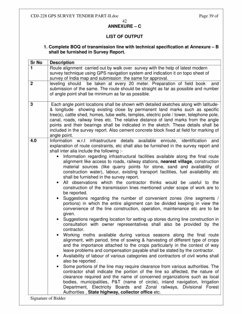
CDJ-228 GPS SURVEY TENDER PART-II.doc Page 39 of
42
Signature of Bidder
ANNEXURE – C
LIST OF OUTPUT
1. Complete BOQ of transmission line with technical specification at Annexure – B shall be furnished in Survey Report.
Sr No Description 1 Route alignment carried out by walk over survey with the help of latest modern
survey technique using GPS navigation system and indication it on topo sheet of survey of India map and submission the same for approval.
2 leveling should be taken at every 20 meter. Preparation of field book and submission of the same. The route should be straight as far as possible and number of angle point shall be minimum as far as possible.
3
Each angle point locations shall be shown with detailed sketches along with latitude-& longitude showing existing close by permanent land marks such as specific tree(s), cattle shed, homes, tube wells, temples, electric pole / tower, telephone pole, canal, roads, railway lines etc. The relative distance of land marks from the angle points and their bearings shall be indicated in the sketch. These details shall be included in the survey report. Also cement concrete block fixed at field for marking of angle point.
4.0
Information w.r.t infrastructure details available enroute, identification and explanation of route constraints, etc shall also be furnished in the survey report and shall inter alia include the following :-
• Information regarding infrastructural facilities available along the final route alignment like access to roads, railway stations, nearest village, construction material sources (like quarry points for stone, sand and availability of construction water), labour, existing transport facilities, fuel availability etc shall be furnished in the survey report.
• All observations which the contractor thinks would be useful to the construction of the transmission lines mentioned under scope of work are to be reported.
• Suggestions regarding the number of convenient zones (line segments / portions) in which the entire alignment can be divided keeping in view the convenience of the line construction, operation, maintenance etc are to be given.
• Suggestions regarding location for setting up stores during line construction in consultation with owner representatives shall also be provided by the contractor.
• Working moths available during various seasons along the final route alignment, with period, time of sowing & harvesting of different type of crops and the importance attached to the crops particularly in the context of way leave problems and compensation payable shall be stated by the contractor.
• Availability of labour of various categories and contractors of civil works shall also be reported .
• Some portions of the line may require clearance from various authorities. The contractor shall indicate the portion of the line so affected, the nature of clearance required and the name of concerned organizations such as local bodies, municipalities, P&T (name of circle), inland navigation, Irrigation Department, Electricity Boards and Zonal railways, Divisional Forest Authorities , State highway, collector office etc.

CDJ-228 GPS SURVEY TENDER PART-II.doc Page 40 of
42
Signature of Bidder
• All the requisite data for processing the case of statutory clearances such as PTCC, Forest and Railway & Highway Authority shall be provided along with the report.
• The details pertaining to pollution levels envisaged along the transmission lines.
• Six copies of survey reports (Hard & soft ) shall be furnished by the contractor to the owner.
• Tower spotting on profile as per technical parameter furnished at Annexure- A.
• Profiles prepared using PLSCADD software shall be submitted for approval.
• Profiles shall be indicating of level , type of tower , line crossing clearance over Railway / Highway/ Line crossing etc on profile base on level and clearance of various crossing.
• Separate profiles for river crossing indicating span, HFL level , type of tower proposed , soil investigation report , suggestion for type of foundation to be adopt etc.
1) Soil resistitivity report at every 3 KM . 2) Trial pit shall be excavated at every 3 KM having depth of 3 meter and
width of 1x1 meter. Detail of soil table shall be indicated for deciding type of foundation will encountered.
3) Soil investigation for river crossing tower shall be carried out and full detail should be submitted.
4) EHT line consisting name of line, voltage class and crossing section and type of towers of existing line.
5) Railway crossing detail consisting gauge, nearest Railway station, Railway pole detail section where proposed line will cross.
6) Forest area , Forest authority etc for submitting proposal for approval during execution of work.
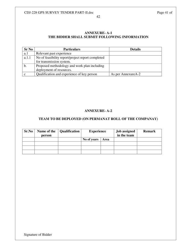
CDJ-228 GPS SURVEY TENDER PART-II.doc Page 41 of
42
Signature of Bidder
ANNEXURE- A-1
THE BIDDER SHALL SUBMIT FOLLOWING INFORMATION
Sr No Particulars Details
a.1 Relevant past experience
a.1.1 No of feasibility report/project report completed
for transmission system.
b. Proposed methodology and work plan including
deployment of resources.
c Qualification and experience of key person As per AnnexureA-2
ANNEXURE- A-2
TEAM TO BE DEPLOYED (ON PERMANAT ROLL OF THE COMPANAY)
Sr.No Name of the
person
Qualification Experience Job assigned
in the team
Remark
No of years Area
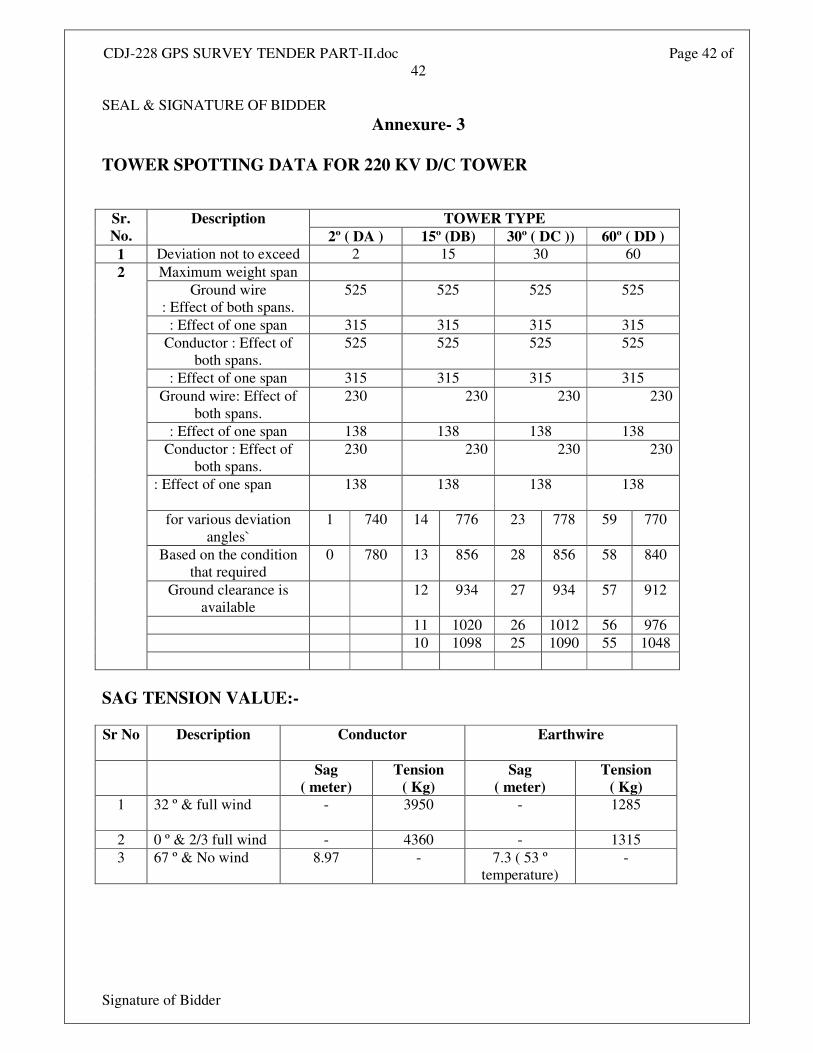
CDJ-228 GPS SURVEY TENDER PART-II.doc Page 42 of
42
Signature of Bidder
SEAL & SIGNATURE OF BIDDER
Annexure- 3
TOWER SPOTTING DATA FOR 220 KV D/C TOWER
TOWER TYPE Sr.
No.
Description
2º ( DA ) 15º (DB) 30º ( DC )) 60º ( DD )
1 Deviation not to exceed 2 15 30 60
Maximum weight span
Ground wire
: Effect of both spans.
525 525 525 525
: Effect of one span 315 315 315 315
Conductor : Effect of
both spans.
525 525 525 525
: Effect of one span 315 315 315 315
Ground wire: Effect of
both spans.
230 230 230 230
: Effect of one span 138 138 138 138
Conductor : Effect of
both spans.
230 230 230 230
: Effect of one span
138 138 138 138
for various deviation
angles`
1 740 14 776 23 778 59 770
Based on the condition
that required
0 780 13 856 28 856 58 840
Ground clearance is
available 12 934 27 934 57 912
11 1020 26 1012 56 976
10 1098 25 1090 55 1048
2
SAG TENSION VALUE:-
Sr No Description Conductor Earthwire
Sag
( meter)
Tension
( Kg)
Sag
( meter)
Tension
( Kg)
1 32 º & full wind - 3950
- 1285
2 0 º & 2/3 full wind - 4360 - 1315
3 67 º & No wind 8.97 - 7.3 ( 53 º
temperature)
-
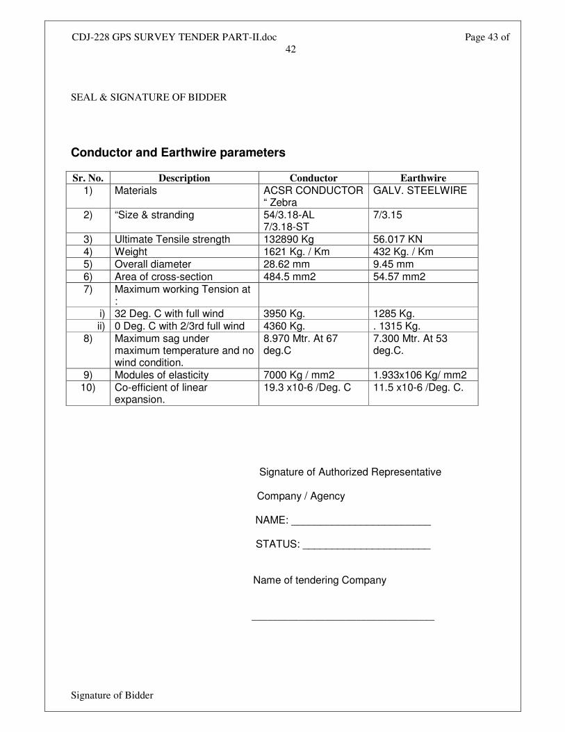
CDJ-228 GPS SURVEY TENDER PART-II.doc Page 43 of
42
Signature of Bidder
SEAL & SIGNATURE OF BIDDER
Conductor and Earthwire parameters
Sr. No. Description Conductor Earthwire
1) Materials ACSR CONDUCTOR “ Zebra
GALV. STEELWIRE
2) “Size & stranding 54/3.18-AL 7/3.18-ST
7/3.15
3) Ultimate Tensile strength 132890 Kg 56.017 KN 4) Weight 1621 Kg. / Km 432 Kg. / Km 5) Overall diameter 28.62 mm 9.45 mm 6) Area of cross-section 484.5 mm2 54.57 mm2 7) Maximum working Tension at
:
i) 32 Deg. C with full wind 3950 Kg. 1285 Kg. ii) 0 Deg. C with 2/3rd full wind 4360 Kg. . 1315 Kg.
8) Maximum sag under maximum temperature and no wind condition.
8.970 Mtr. At 67 deg.C
7.300 Mtr. At 53 deg.C.
9) Modules of elasticity 7000 Kg / mm2 1.933x10⁶ Kg/ mm2 10) Co-efficient of linear
expansion. 19.3 x10⁻⁶ /Deg. C 11.5 x10⁻⁶ /Deg. C.
Signature of Authorized Representative
Company / Agency
NAME: ________________________
STATUS: ______________________
Name of tendering Company
___________________________________
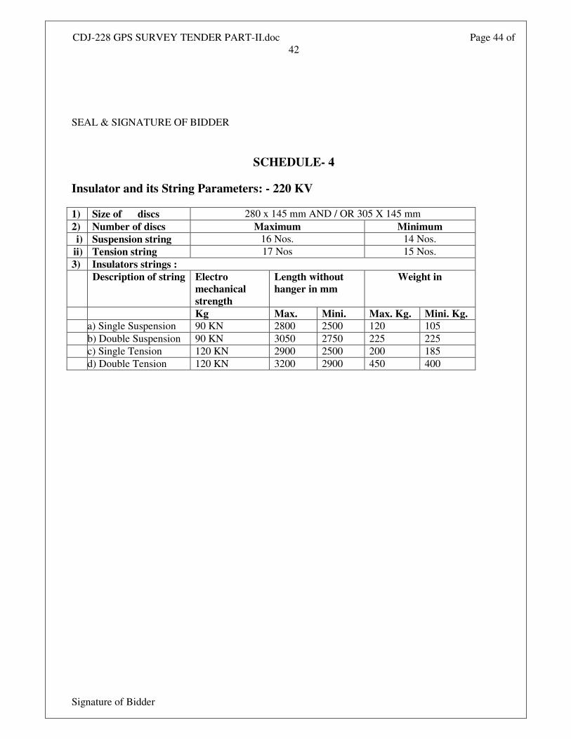
CDJ-228 GPS SURVEY TENDER PART-II.doc Page 44 of
42
Signature of Bidder
SEAL & SIGNATURE OF BIDDER
SCHEDULE- 4
Insulator and its String Parameters: - 220 KV
1) Size of discs 280 x 145 mm AND / OR 305 X 145 mm
2) Number of discs Maximum Minimum
i) Suspension string 16 Nos. 14 Nos.
ii) Tension string 17 Nos 15 Nos.
3) Insulators strings :
Description of string Electro
mechanical
strength
Length without
hanger in mm
Weight in
Kg Max. Mini. Max. Kg. Mini. Kg.
a) Single Suspension 90 KN 2800 2500 120 105
b) Double Suspension 90 KN 3050 2750 225 225
c) Single Tension 120 KN 2900 2500 200 185
d) Double Tension 120 KN 3200 2900 450 400

CDJ-228 GPS SURVEY TENDER PART-II.doc Page 45 of
42
Signature of Bidder
SEAL & SIGNATURE OF BIDDER