Technical Data 10911 HCM1A0703V2 - Eaton...Product features • AEC-Q200 qualified ......
14
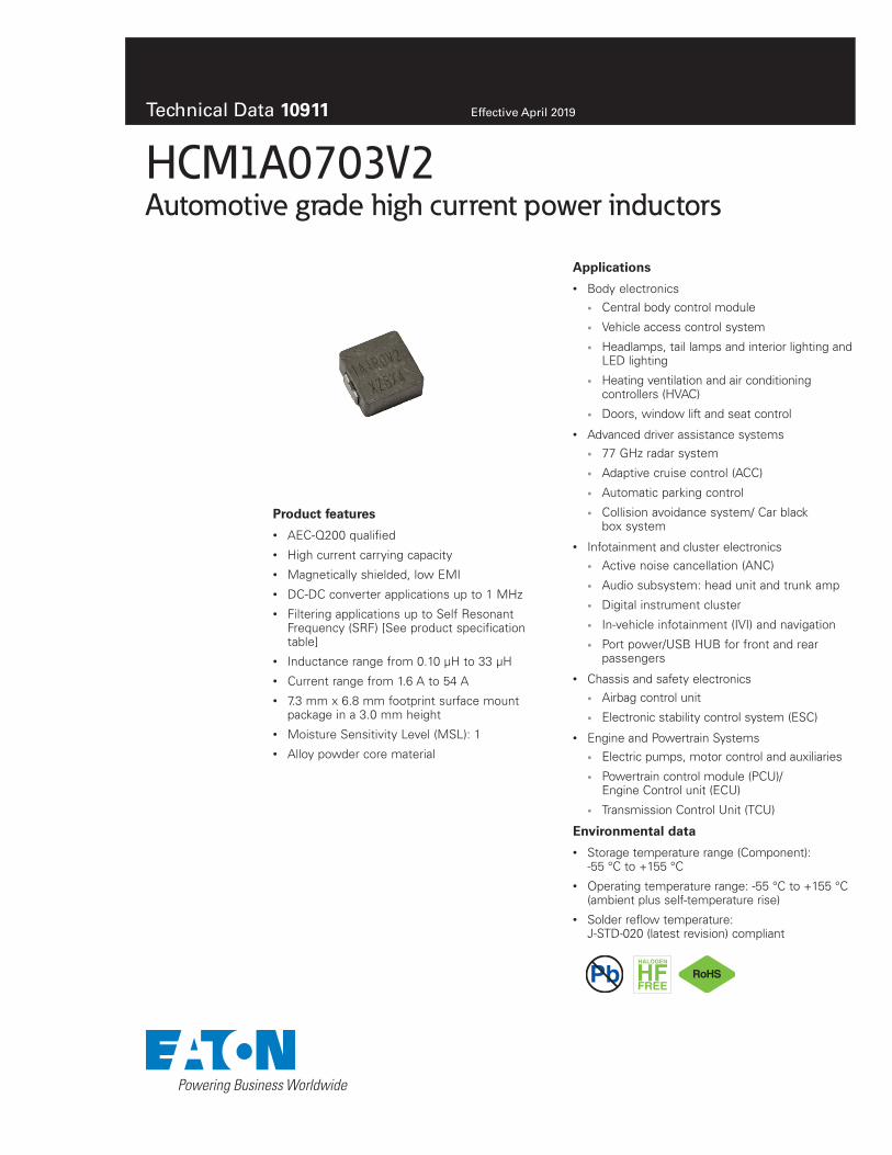
Technical Data 10911 Effective April 2019 HCM1A0703V2 Automotive grade high current power inductors Product features • AEC-Q200 qualified • High current carrying capacity • Magnetically shielded, low EMI • DC-DC converter applications up to 1 MHz • Filtering applications up to Self Resonant Frequency (SRF) [See product specification table] • Inductance range from 0.10 μH to 33 μH • Current range from 1.6 A to 54 A • 7.3 mm x 6.8 mm footprint surface mount package in a 3.0 mm height • Moisture Sensitivity Level (MSL): 1 • Alloy powder core material Applications • Body electronics • Central body control module • Vehicle access control system • Headlamps, tail lamps and interior lighting and LED lighting • Heating ventilation and air conditioning controllers (HVAC) • Doors, window lift and seat control • Advanced driver assistance systems • 77 GHz radar system • Adaptive cruise control (ACC) • Automatic parking control • Collision avoidance system/ Car black box system • Infotainment and cluster electronics • Active noise cancellation (ANC) • Audio subsystem: head unit and trunk amp • Digital instrument cluster • In-vehicle infotainment (IVI) and navigation • Port power/USB HUB for front and rear passengers • Chassis and safety electronics • Airbag control unit • Electronic stability control system (ESC) • Engine and Powertrain Systems • Electric pumps, motor control and auxiliaries • Powertrain control module (PCU)/ Engine Control unit (ECU) • Transmission Control Unit (TCU) Environmental data • Storage temperature range (Component): -55 °C to +155 °C • Operating temperature range: -55 °C to +155 °C (ambient plus self-temperature rise) • Solder reflow temperature: J-STD-020 (latest revision) compliant Pb HALOGEN HF FREE
Transcript of Technical Data 10911 HCM1A0703V2 - Eaton...Product features • AEC-Q200 qualified ......
Technical Data 10911 Effective April 2019
HCM1A0703V2Automotive grade high current power inductors
Product features
• AEC-Q200 qualified• High current carrying capacity• Magnetically shielded, low EMI• DC-DC converter applications up to 1 MHz• Filtering applications up to Self Resonant
Frequency (SRF) [See product specificationtable]
• Inductance range from 0.10 μH to 33 μH• Current range from 1.6 A to 54 A• 7.3 mm x 6.8 mm footprint surface mount
package in a 3.0 mm height• Moisture Sensitivity Level (MSL): 1• Alloy powder core material
Applications
• Body electronics• Central body control module
• Vehicle access control system
• Headlamps, tail lamps and interior lighting andLED lighting
• Heating ventilation and air conditioningcontrollers (HVAC)
• Doors, window lift and seat control
• Advanced driver assistance systems• 77 GHz radar system
• Adaptive cruise control (ACC)
• Automatic parking control
• Collision avoidance system/ Car blackbox system
• Infotainment and cluster electronics• Active noise cancellation (ANC)
• Audio subsystem: head unit and trunk amp
• Digital instrument cluster
• In-vehicle infotainment (IVI) and navigation
• Port power/USB HUB for front and rearpassengers
• Chassis and safety electronics• Airbag control unit
• Electronic stability control system (ESC)
• Engine and Powertrain Systems• Electric pumps, motor control and auxiliaries
• Powertrain control module (PCU)/Engine Control unit (ECU)
• Transmission Control Unit (TCU)
Environmental data
• Storage temperature range (Component):-55 °C to +155 °C
• Operating temperature range: -55 °C to +155 °C(ambient plus self-temperature rise)
• Solder reflow temperature:J-STD-020 (latest revision) compliant
PbHALOGEN
HFFREE
2
Technical Data 10911Effective April 2019
HCM1A0703V2 Automotive grade high current power inductors
www.eaton.com/electronics
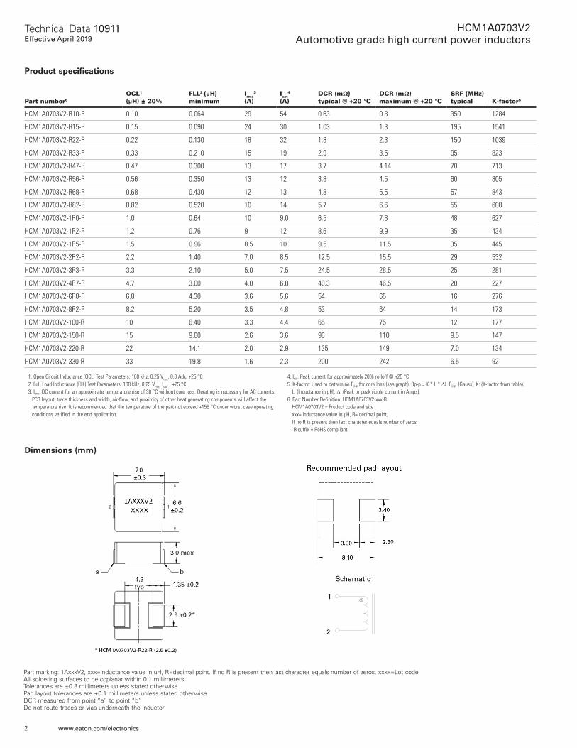
Part marking: 1AxxxV2, xxx=inductance value in uH, R=decimal point. If no R is present then last character equals number of zeros. xxxx=Lot code All soldering surfaces to be coplanar within 0.1 millimeters Tolerances are ±0.3 millimeters unless stated otherwise Pad layout tolerances are ±0.1 millimeters unless stated otherwise DCR measured from point “a” to point “b” Do not route traces or vias underneath the inductor
Dimensions (mm)
Schematic
1
2
Product specifications
Part number6OCL1 (μH) ± 20%
FLL2 (μH) minimum
Irms3
(A)Isat
4 (A)
DCR (mΩ) typical @ +20 °C
DCR (mΩ) maximum @ +20 °C
SRF (MHz) typical K-factor5
HCM1A0703V2-R10-R 0.10 0.064 29 54 0.63 0.8 350 1284
HCM1A0703V2-R15-R 0.15 0.090 24 30 1.03 1.3 195 1541
HCM1A0703V2-R22-R 0.22 0.130 18 32 1.8 2.3 150 1039
HCM1A0703V2-R33-R 0.33 0.210 15 19 2.9 3.5 95 823
HCM1A0703V2-R47-R 0.47 0.300 13 17 3.7 4.14 70 713
HCM1A0703V2-R56-R 0.56 0.350 13 12 3.8 4.5 60 805
HCM1A0703V2-R68-R 0.68 0.430 12 13 4.8 5.5 57 843
HCM1A0703V2-R82-R 0.82 0.520 10 14 5.7 6.6 55 608
HCM1A0703V2-1R0-R 1.0 0.64 10 9.0 6.5 7.8 48 627
HCM1A0703V2-1R2-R 1.2 0.76 9 12 8.6 9.9 35 434
HCM1A0703V2-1R5-R 1.5 0.96 8.5 10 9.5 11.5 35 445
HCM1A0703V2-2R2-R 2.2 1.40 7.0 8.5 12.5 15.5 29 532
HCM1A0703V2-3R3-R 3.3 2.10 5.0 7.5 24.5 28.5 25 281
HCM1A0703V2-4R7-R 4.7 3.00 4.0 6.8 40.3 46.5 20 227
HCM1A0703V2-6R8-R 6.8 4.30 3.6 5.6 54 65 16 276
HCM1A0703V2-8R2-R 8.2 5.20 3.5 4.8 53 64 14 173
HCM1A0703V2-100-R 10 6.40 3.3 4.4 65 75 12 177
HCM1A0703V2-150-R 15 9.60 2.6 3.6 96 110 9.5 147
HCM1A0703V2-220-R 22 14.1 2.0 2.9 135 149 7.0 134
HCM1A0703V2-330-R 33 19.8 1.6 2.3 200 242 6.5 92
1. Open Circuit Inductance (OCL) Test Parameters: 100 kHz, 0.25 Vrms, 0.0 Adc, +25 °C2. Full Load Inductance (FLL) Test Parameters: 100 kHz, 0.25 Vrms, Isat, , +25 °C3. Irms: DC current for an approximate temperature rise of 30 °C without core loss. Derating is necessary for AC currents.
PCB layout, trace thickness and width, air-flow, and proximity of other heat generating components will affect the temperature rise. It is recommended that the temperature of the part not exceed +155 °C under worst case operating conditions verified in the end application.
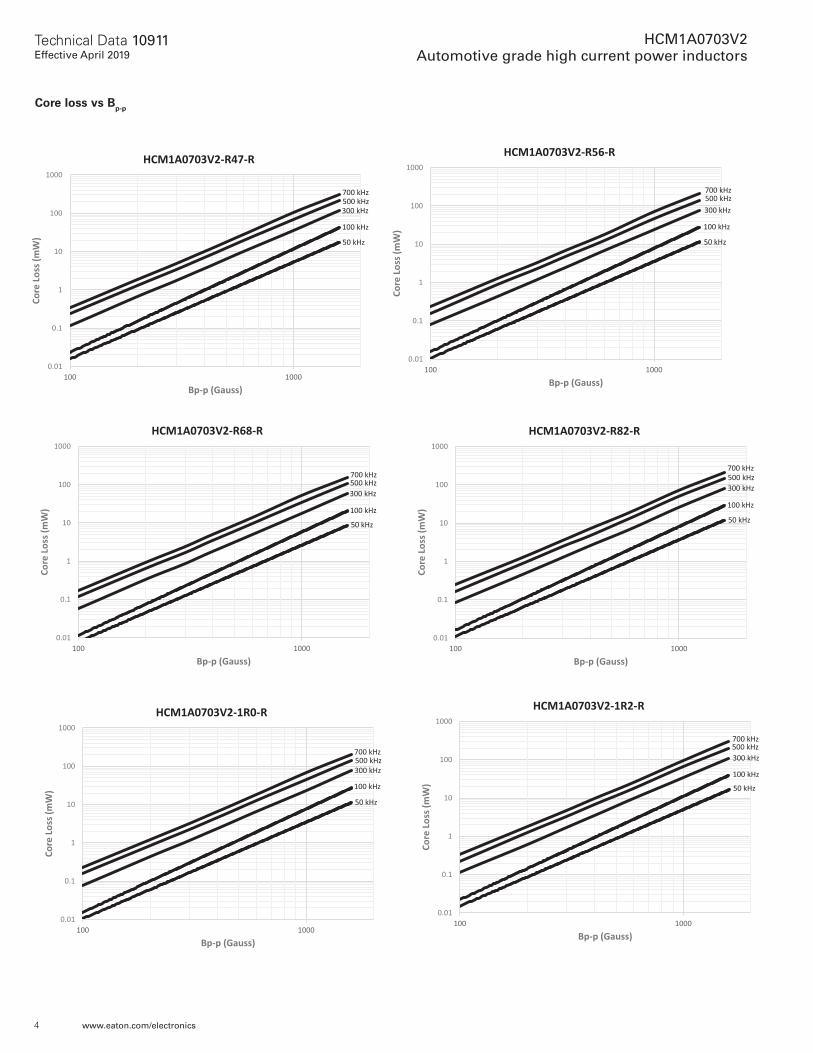
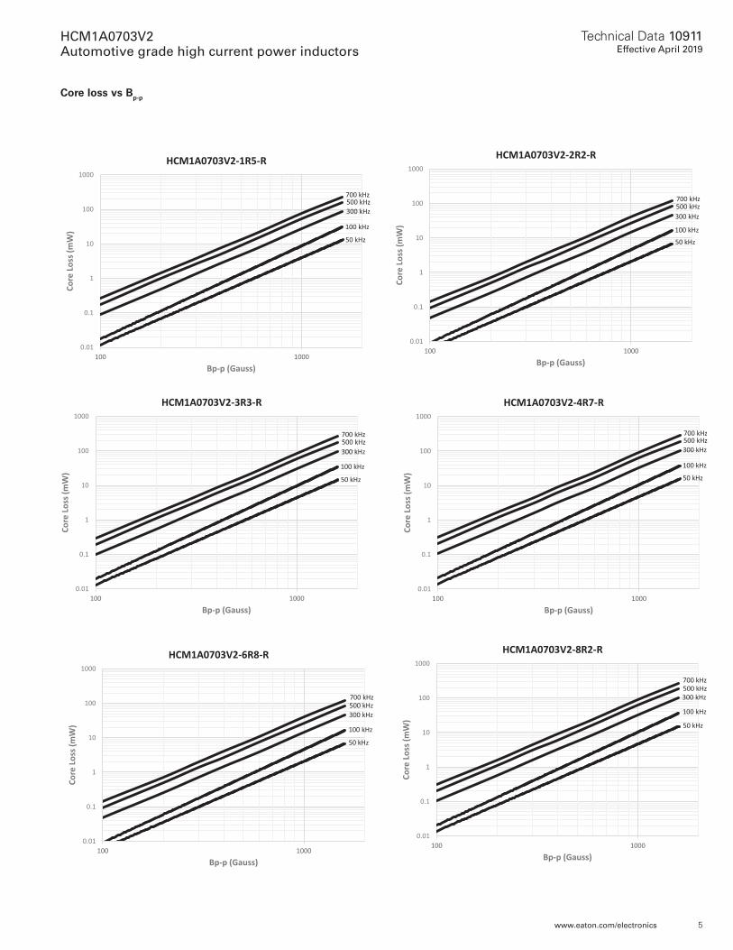
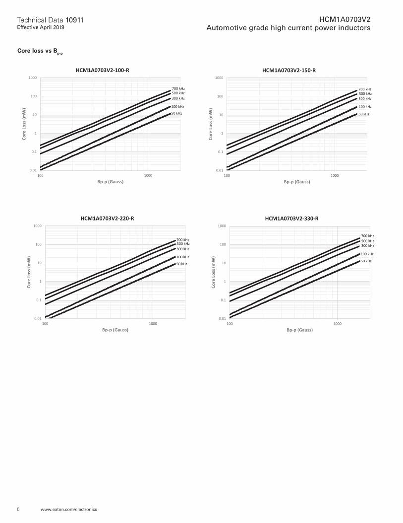
4. Isat: Peak current for approximately 20% rolloff @ +25 °C5. K-factor: Used to determine Bp-p for core loss (see graph). Bp-p = K * L * ΔI. Bp-p: (Gauss), K: (K-factor from table),
L: (Inductance in μH), ΔI (Peak to peak ripple current in Amps).6. Part Number Definition: HCM1A0703V2-xxx-R
HCM1A0703V2 = Product code and size xxx= inductance value in μH, R= decimal point, If no R is present then last character equals number of zeros -R suffix = RoHS compliant
3
Technical Data 10911Effective April 2019
HCM1A0703V2 Automotive grade high current power inductors
www.eaton.com/electronics
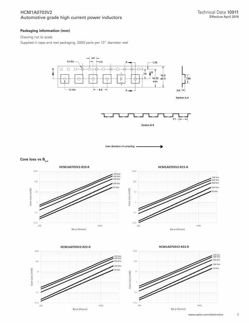
Packaging information (mm)
Drawing not to scale
Supplied in tape and reel packaging, 2000 parts per 13” diameter reel
Core loss vs Bp-p
0.01
0.1
1
10
100
1000
100 1000
Core
Loss
(mW
)
Bp-p (Gauss)
50 kHz
HCM1A0703V2-R10-R
100 kHz
300 kHz500 kHz700 kHz
0.01
0.1
1
10
100
1000
100 1000
Core
Loss
(mW
)
Bp-p (Gauss)
50 kHz
HCM1A0703V2-R15-R
100 kHz
300 kHz500 kHz700 kHz
0.01
0.1
1
10
100
1000
100 1000
Core
Loss
(mW
)
Bp-p (Gauss)
50 kHz
HCM1A0703V2-R22-R
100 kHz
300 kHz500 kHz700 kHz
0.01
0.1
1
10
100
1000
100 1000
Core
Loss
(mW
)
Bp-p (Gauss)
50 kHz
HCM1A0703V2-R33-R
100 kHz
300 kHz500 kHz700 kHz
4
Technical Data 10911Effective April 2019
HCM1A0703V2 Automotive grade high current power inductors
www.eaton.com/electronics
Core loss vs Bp-p
0.01
0.1
1
10
100
1000
100 1000
Core
Loss
(mW
)
Bp-p (Gauss)
50 kHz
HCM1A0703V2-R68-R
100 kHz
300 kHz500 kHz700 kHz
0.01
0.1
1
10
100
1000
100 1000
Core
Loss
(mW
)
Bp-p (Gauss)
50 kHz
HCM1A0703V2-R82-R
100 kHz
300 kHz500 kHz700 kHz
0.01
0.1
1
10
100
1000
100 1000
Core
Loss
(mW
)
Bp-p (Gauss)
50 kHz
HCM1A0703V2-1R0-R
100 kHz
300 kHz500 kHz700 kHz
0.01
0.1
1
10
100
1000
100 1000
Core
Loss
(mW
)
Bp-p (Gauss)
50 kHz
HCM1A0703V2-1R2-R
100 kHz
300 kHz500 kHz700 kHz
0.01
0.1
1
10
100
1000
100 1000
Core
Loss
(mW
)
Bp-p (Gauss)
50 kHz
HCM1A0703V2-R47-R
100 kHz
300 kHz500 kHz700 kHz
0.01
0.1
1
10
100
1000
100 1000
Core
Loss
(mW
)Bp-p (Gauss)
50 kHz
HCM1A0703V2-R56-R
100 kHz
300 kHz500 kHz700 kHz
5
Technical Data 10911Effective April 2019
HCM1A0703V2 Automotive grade high current power inductors
www.eaton.com/electronics
Core loss vs Bp-p
0.01
0.1
1
10
100
1000
100 1000
Core
Loss
(mW
)
Bp-p (Gauss)
50 kHz
HCM1A0703V2-3R3-R
100 kHz
300 kHz500 kHz700 kHz
0.01
0.1
1
10
100
1000
100 1000
Core
Loss
(mW
)
Bp-p (Gauss)
50 kHz
HCM1A0703V2-1R5-R
100 kHz
300 kHz500 kHz700 kHz
0.01
0.1
1
10
100
1000
100 1000
Core
Loss
(mW
)
Bp-p (Gauss)
50 kHz
HCM1A0703V2-2R2-R
100 kHz
300 kHz500 kHz700 kHz
0.01
0.1
1
10
100
1000
100 1000
Core
Loss
(mW
)
Bp-p (Gauss)
50 kHz
HCM1A0703V2-4R7-R
100 kHz
300 kHz500 kHz700 kHz
0.01
0.1
1
10
100
1000
100 1000
Core
Loss
(mW
)
Bp-p (Gauss)
50 kHz
HCM1A0703V2-6R8-R
100 kHz
300 kHz500 kHz700 kHz
0.01
0.1
1
10
100
1000
100 1000
Core
Loss
(mW
)
Bp-p (Gauss)
50 kHz
HCM1A0703V2-8R2-R
100 kHz
300 kHz500 kHz700 kHz
6
Technical Data 10911Effective April 2019
HCM1A0703V2 Automotive grade high current power inductors
www.eaton.com/electronics
0.01
0.1
1
10
100
1000
100 1000
Core
Loss
(mW
)
Bp-p (Gauss)
50 kHz
HCM1A0703V2-100-R
100 kHz
300 kHz500 kHz700 kHz
0.01
0.1
1
10
100
1000
100 1000
Core
Loss
(mW
)
Bp-p (Gauss)
50 kHz
HCM1A0703V2-150-R
100 kHz
300 kHz500 kHz700 kHz
0.01
0.1
1
10
100
1000
100 1000
Core
Loss
(mW
)
Bp-p (Gauss)
50 kHz
HCM1A0703V2-220-R
100 kHz
300 kHz500 kHz700 kHz
0.01
0.1
1
10
100
1000
100 1000
Core
Loss
(mW
)
Bp-p (Gauss)
50 kHz
HCM1A0703V2-330-R
100 kHz
300 kHz500 kHz700 kHz
Core loss vs Bp-p
7
Technical Data 10911Effective April 2019
HCM1A0703V2 Automotive grade high current power inductors
www.eaton.com/electronics
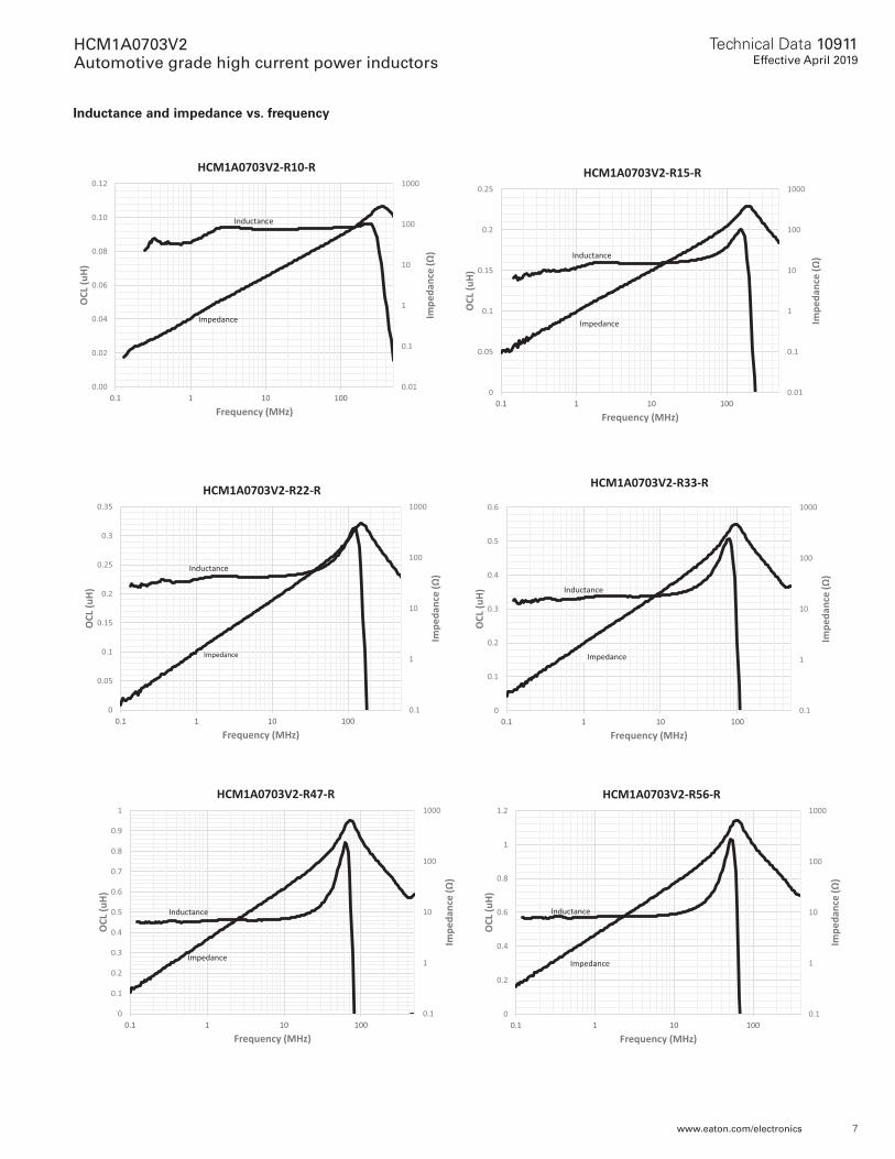
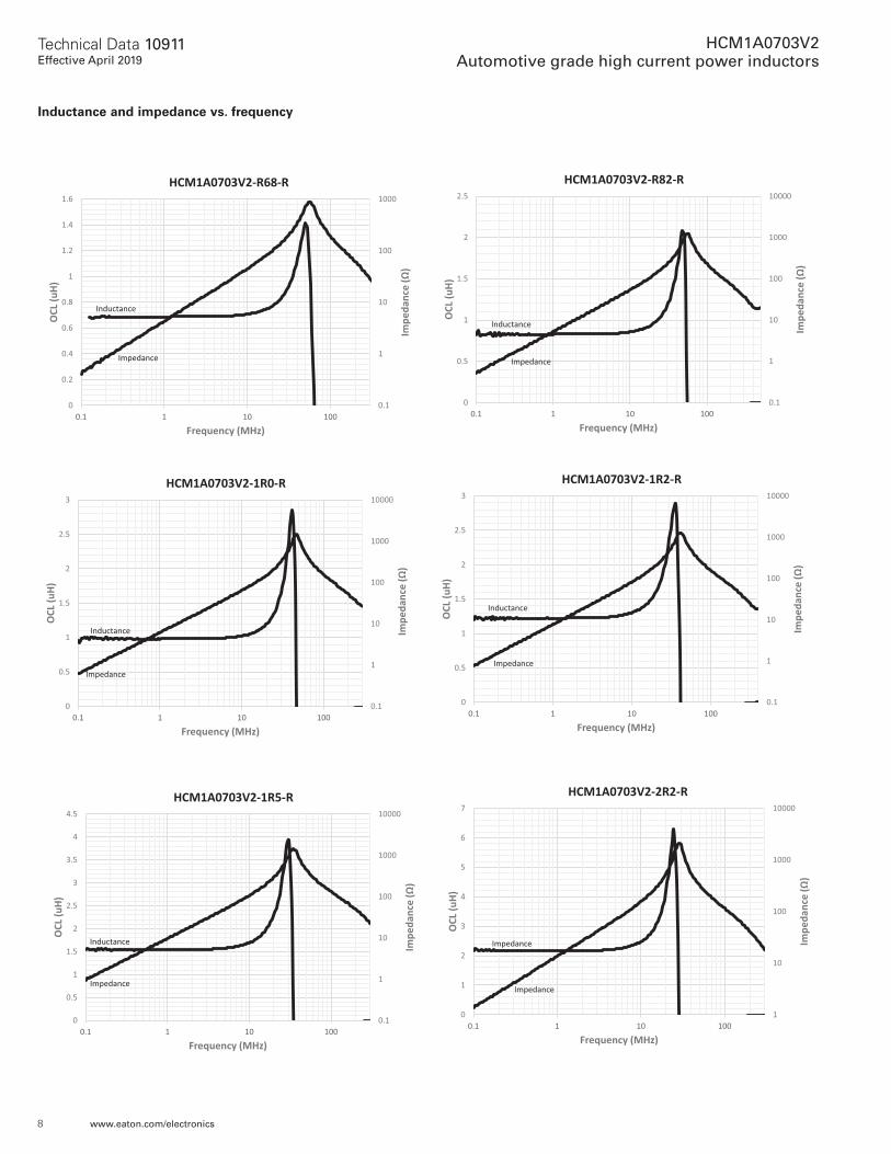
Inductance and impedance vs. frequency
0.01
0.1
1
10
100
1000
0.00
0.02
0.04
0.06
0.08
0.10
0.12
0.1 1 10 100
Impe
danc
e (Ω
)
OCL
(uH)
Frequency (MHz)
HCM1A0703V2-R10-R
Inductance
Impedance
0.01
0.1
1
10
100
1000
0
0.05
0.1
0.15
0.2
0.25
0.1 1 10 100
Impe
danc
e (Ω
)
OCL
(uH)
Frequency (MHz)
HCM1A0703V2-R15-R
Inductance
Impedance
0.1
1
10
100
1000
0
0.05
0.1
0.15
0.2
0.25
0.3
0.35
0.1 1 10 100
Impe
danc
e (Ω
)
OCL
(uH)
Frequency (MHz)
HCM1A0703V2-R22-R
Inductance
Impedance
0.1
1
10
100
1000
0
0.1
0.2
0.3
0.4
0.5
0.6
0.1 1 10 100
Impe
danc
e (Ω
)
OCL
(uH)
Frequency (MHz)
HCM1A0703V2-R33-R
Inductance
Impedance
0.1
1
10
100
1000
0
0.1
0.2
0.3
0.4
0.5
0.6
0.7
0.8
0.9
1
0.1 1 10 100
Impe
danc
e (Ω
)
OCL
(uH)
Frequency (MHz)
HCM1A0703V2-R47-R
Inductance
Impedance
0.1
1
10
100
1000
0
0.2
0.4
0.6
0.8
1
1.2
0.1 1 10 100
Impe
danc
e (Ω
)
OCL
(uH)
Frequency (MHz)
HCM1A0703V2-R56-R
Inductance
Impedance
8
Technical Data 10911Effective April 2019
HCM1A0703V2 Automotive grade high current power inductors
www.eaton.com/electronics
Inductance and impedance vs. frequency
0.1
1
10
100
1000
0
0.2
0.4
0.6
0.8
1
1.2
1.4
1.6
0.1 1 10 100Im
peda
nce
(Ω)
OCL (
uH)
Frequency (MHz)
HCM1A0703V2-R68-R
Inductance
Impedance
0.1
1
10
100
1000
10000
0
0.5
1
1.5
2
2.5
0.1 1 10 100
Impe
danc
e (Ω
)
OCL (
uH)
Frequency (MHz)
HCM1A0703V2-R82-R
Inductance
Impedance
0.1
1
10
100
1000
10000
0
0.5
1
1.5
2
2.5
3
0.1 1 10 100
Impe
danc
e (Ω
)
OCL (
uH)
Frequency (MHz)
HCM1A0703V2-1R0-R
Inductance
Impedance
0.1
1
10
100
1000
10000
0
0.5
1
1.5
2
2.5
3
0.1 1 10 100
Impe
danc
e (Ω
)
OCL (
uH)
Frequency (MHz)
HCM1A0703V2-1R2-R
Inductance
Impedance
0.1
1
10
100
1000
10000
0
0.5
1
1.5
2
2.5
3
3.5
4
4.5
0.1 1 10 100
Impe
danc
e (Ω
)
OCL (
uH)
Frequency (MHz)
HCM1A0703V2-1R5-R
Inductance
Impedance
1
10
100
1000
10000
0
1
2
3
4
5
6
7
0.1 1 10 100
Impe
danc
e (Ω
)
OCL (
uH)
Frequency (MHz)
HCM1A0703V2-2R2-R
Impedance
Impedance
9
Technical Data 10911Effective April 2019
HCM1A0703V2 Automotive grade high current power inductors
www.eaton.com/electronics
1
10
100
1000
10000
0
1
2
3
4
5
6
7
8
0.1 1 10 100
Impe
danc
e (Ω
)
OCL
(uH)
Frequency (MHz)
HCM1A0703V2-3R3-R
Inductance
Impedance
0.1
1
10
100
1000
10000
0
2
4
6
8
10
12
0.1 1 10 100
Impe
danc
e (Ω
)
OCL
(uH)
Frequency (MHz)
HCM1A0703V2-4R7-R
Inductance
Impedance
1
10
100
1000
10000
0
2
4
6
8
10
12
14
16
18
0.1 1 10 100
Impe
danc
e (Ω
)
OCL
(uH)
Frequency (MHz)
HCM1A0703V2-6R8-R
Inductance
Impedance
1
10
100
1000
10000
0
5
10
15
20
25
0.1 1 10 100
Impe
danc
e (Ω
)
OCL
(uH)
Frequency (MHz)
HCM1A0703V2-8R2-R
Inductance
Impedance
1
10
100
1000
10000
0
5
10
15
20
25
30
35
0.1 1 10 100
Impe
danc
e (Ω
)
OCL
(uH)
Frequency (MHz)
HCM1A0703V2-100-R
Inductance
Impedance
10
100
1000
10000
0
5
10
15
20
25
30
35
40
45
0.1 1 10 100
Impe
danc
e (Ω
)
OCL
(uH)
Frequency (MHz)
HCM1A0703V2-150-R
Inductance
Impedance
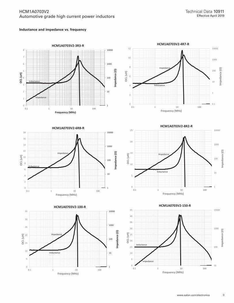
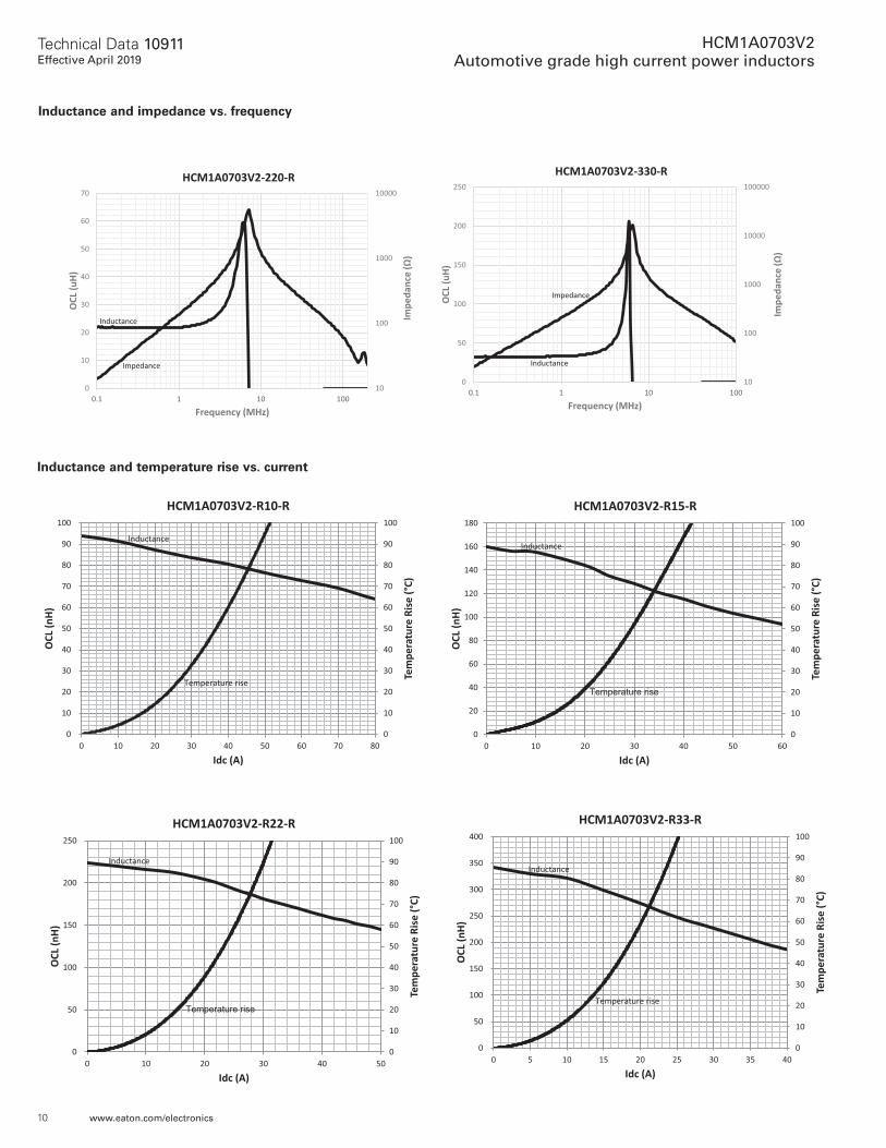
Inductance and impedance vs. frequency
10
Technical Data 10911Effective April 2019
HCM1A0703V2 Automotive grade high current power inductors
www.eaton.com/electronics
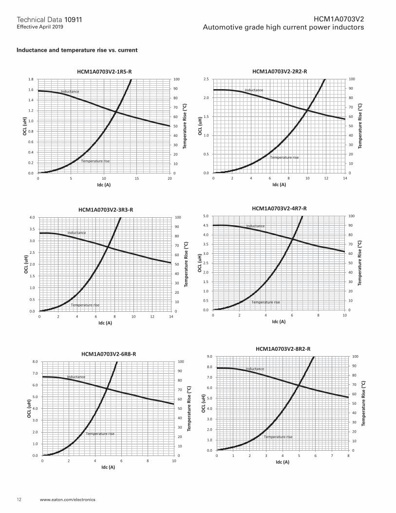
Inductance and temperature rise vs. current
10
100
1000
10000
0
10
20
30
40
50
60
70
0.1 1 10 100Im
peda
nce
(Ω)
OCL
(uH)
Frequency (MHz)
HCM1A0703V2-220-R
Inductance
Impedance
10
100
1000
10000
100000
0
50
100
150
200
250
0.1 1 10 100
Impe
danc
e (Ω
)
OCL
(uH)
Frequency (MHz)
HCM1A0703V2-330-R
Inductance
Impedance
Inductance and impedance vs. frequency
0
10
20
30
40
50
60
70
80
90
100
0
10
20
30
40
50
60
70
80
90
100
0 10 20 30 40 50 60 70 80
OCL (
nH)
Tem
pera
ture
Rise
(°C)
Idc (A)
HCM1A0703V2-R10-R
Inductance
Temperature rise
0
10
20
30
40
50
60
70
80
90
100
0
20
40
60
80
100
120
140
160
180
0 10 20 30 40 50 60
OCL (
nH)
Tem
pera
ture
Rise
(°C)
Idc (A)
HCM1A0703V2-R15-R
Inductance
Temperature rise
0
10
20
30
40
50
60
70
80
90
100
0
50
100
150
200
250
0 10 20 30 40 50
OCL (
nH)
Tem
pera
ture
Rise
(°C)
Idc (A)
HCM1A0703V2-R22-R
Inductance
Temperature rise
0
10
20
30
40
50
60
70
80
90
100
0
50
100
150
200
250
300
350
400
0 5 10 15 20 25 30 35 40
OCL (
nH)
Tem
pera
ture
Rise
(°C)
Idc (A)
HCM1A0703V2-R33-R
Inductance
Temperature rise
11
Technical Data 10911Effective April 2019
HCM1A0703V2 Automotive grade high current power inductors
www.eaton.com/electronics
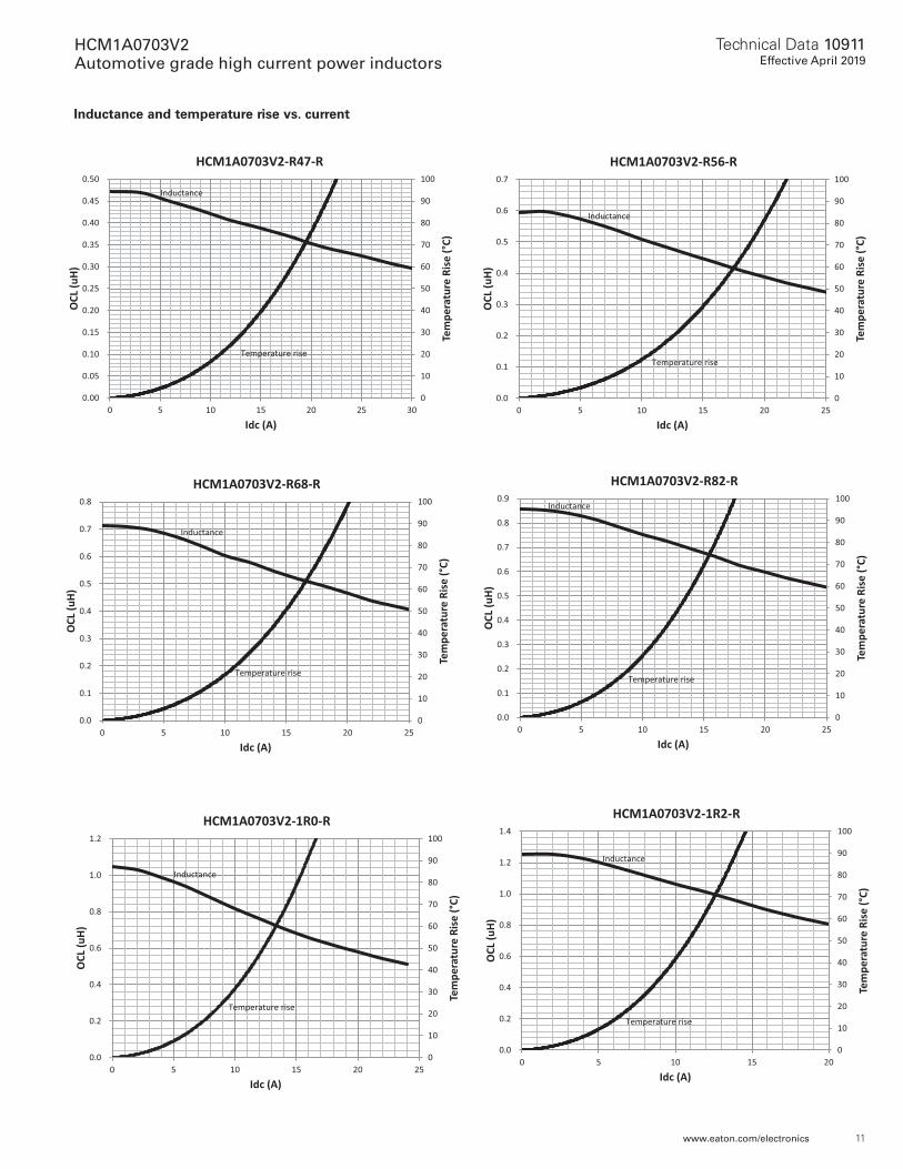
Inductance and temperature rise vs. current
0
10
20
30
40
50
60
70
80
90
100
0.00
0.05
0.10
0.15
0.20
0.25
0.30
0.35
0.40
0.45
0.50
0 5 10 15 20 25 30
OCL (
uH)
Tem
pera
ture
Rise
(°C)
Idc (A)
HCM1A0703V2-R47-R
Inductance
riseTemperature
0
10
20
30
40
50
60
70
80
90
100
0.0
0.1
0.2
0.3
0.4
0.5
0.6
0.7
0 5 10 15 20 25
OCL (
uH)
Tem
pera
ture
Rise
(°C)
Idc (A)
HCM1A0703V2-R56-R
Inductance
riseTemperature
0
10
20
30
40
50
60
70
80
90
100
0.0
0.1
0.2
0.3
0.4
0.5
0.6
0.7
0.8
0 5 10 15 20 25
OCL (
uH)
Tem
pera
ture
Rise
(°C)
Idc (A)
HCM1A0703V2-R68-R
Inductance
riseTemperature
0
10
20
30
40
50
60
70
80
90
100
0.0
0.1
0.2
0.3
0.4
0.5
0.6
0.7
0.8
0.9
0 5 10 15 20 25
OCL (
uH)
Tem
pera
ture
Rise
(°C)
Idc (A)
HCM1A0703V2-R82-RInductance
riseTemperature
0
10
20
30
40
50
60
70
80
90
100
0.0
0.2
0.4
0.6
0.8
1.0
1.2
0 5 10 15 20 25
OCL (
uH)
Tem
pera
ture
Rise
(°C)
Idc (A)
HCM1A0703V2-1R0-R
Inductance
Temperature rise
0
10
20
30
40
50
60
70
80
90
100
0.0
0.2
0.4
0.6
0.8
1.0
1.2
1.4
0 5 10 15 20
OCL (
uH)
Tem
pera
ture
Rise
(°C)
Idc (A)
HCM1A0703V2-1R2-R
Inductance
Temperature rise
12
Technical Data 10911Effective April 2019
HCM1A0703V2 Automotive grade high current power inductors
www.eaton.com/electronics
Inductance and temperature rise vs. current
0
10
20
30
40
50
60
70
80
90
100
0.0
0.2
0.4
0.6
0.8
1.0
1.2
1.4
1.6
1.8
0 5 10 15 20
OCL (
uH)
Tem
pera
ture
Rise
(°C)
Idc (A)
HCM1A0703V2-1R5-R
Inductance
Temperature rise
0
10
20
30
40
50
60
70
80
90
100
0.0
0.5
1.0
1.5
2.0
2.5
0 2 4 6 8 10 12 14
OCL (
uH)
Tem
pera
ture
Rise
(°C)
Idc (A)
HCM1A0703V2-2R2-R
Inductance
riseTemperature
0
10
20
30
40
50
60
70
80
90
100
0.0
0.5
1.0
1.5
2.0
2.5
3.0
3.5
4.0
0 2 4 6 8 10 12 14
OCL (
uH)
Tem
pera
ture
Rise
(°C)
Idc (A)
HCM1A0703V2-3R3-R
Inductance
Temperature rise0
10
20
30
40
50
60
70
80
90
100
0.0
0.5
1.0
1.5
2.0
2.5
3.0
3.5
4.0
4.5
5.0
0 2 4 6 8 10
OCL (
uH)
Tem
pera
ture
Rise
(°C)
Idc (A)
HCM1A0703V2-4R7-R
Inductance
Temperature rise
0
10
20
30
40
50
60
70
80
90
100
0.0
1.0
2.0
3.0
4.0
5.0
6.0
7.0
8.0
0 2 4 6 8 10
OCL (
uH)
Tem
pera
ture
Rise
(°C)
Idc (A)
HCM1A0703V2-6R8-R
Inductance
Temperature rise
0
10
20
30
40
50
60
70
80
90
100
0.0
1.0
2.0
3.0
4.0
5.0
6.0
7.0
8.0
9.0
0 1 2 3 4 5 6 7 8
OCL (
uH)
Tem
pera
ture
Rise
(°C)
Idc (A)
HCM1A0703V2-8R2-R
Inductance
riseTemperature
13
Technical Data 10911Effective April 2019
HCM1A0703V2 Automotive grade high current power inductors
www.eaton.com/electronics
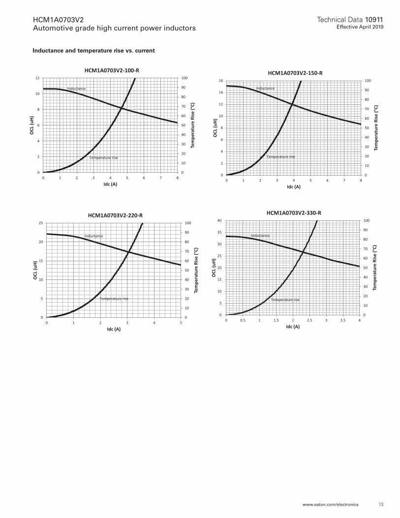
Inductance and temperature rise vs. current
0
10
20
30
40
50
60
70
80
90
100
0
2
4
6
8
10
12
0 1 2 3 4 5 6 7 8
OCL (
uH)
Tem
pera
ture
Rise
(°C)
Idc (A)
HCM1A0703V2-100-R
Inductance
Temperature rise
0
10
20
30
40
50
60
70
80
90
100
0
2
4
6
8
10
12
14
16
0 1 2 3 4 5 6 7 8
OCL (
uH)
Tem
pera
ture
Rise
(°C)
Idc (A)
HCM1A0703V2-150-R
Inductance
Temperature rise
0
10
20
30
40
50
60
70
80
90
100
0
5
10
15
20
25
0 1 2 3 4 5
OCL (
uH)
Tem
pera
ture
Rise
(°C)
Idc (A)
HCM1A0703V2-220-R
Inductance
riseTemperature
0
10
20
30
40
50
60
70
80
90
100
0
5
10
15
20
25
30
35
40
0 0.5 1 1.5 2 2.5 3 3.5 4
OCL (
uH)
Tem
pera
ture
Rise
(°C)
Idc (A)
HCM1A0703V2-330-R
Inductance
riseTemperature
EatonElectronics Division1000 Eaton BoulevardCleveland, OH 44122United Stateswww.eaton.com/electronics
© 2019 EatonAll Rights ReservedPrinted in USAPublication No. 10911 BU-MC19047April 2019
HCM1A0703V2 Automotive grade high current power inductors
Technical Data 10911Effective April 2019
Life Support Policy: Eaton does not authorize the use of any of its products for use in life support devices or systems without the express written approval of an officer of the Company. Life support systems are devices which support or sustain life, and whose failure to perform, when properly used in accordance with instructions for use provided in the labeling, can be reasonably expected to result in significant injury to the user.
Eaton reserves the right, without notice, to change design or construction of any products and to discontinue or limit distribution of any products. Eaton also reserves the right to change or update, without notice, any technical information contained in this bulletin.
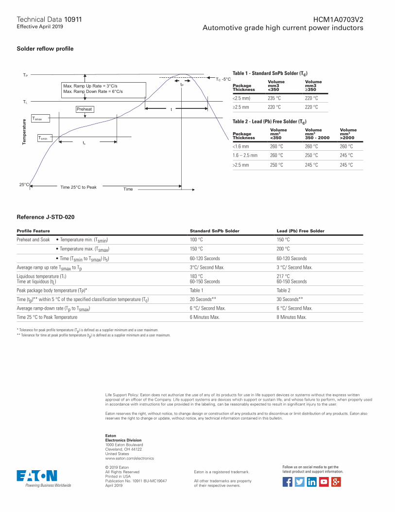
Solder reflow profile
Table 1 - Standard SnPb Solder (Tc)
Package Thickness
Volume mm3 <350
Volume mm3 ≥350
<2.5 mm) 235 °C 220 °C
≥2.5 mm 220 °C 220 °C
Table 2 - Lead (Pb) Free Solder (Tc)
Package Thickness
Volume mm3 <350
Volume mm3 350 - 2000
Volume mm3 >2000
<1.6 mm 260 °C 260 °C 260 °C
1.6 – 2.5 mm 260 °C 250 °C 245 °C
>2.5 mm 250 °C 245 °C 245 °C
Temperature
t
tP
ts
TC -5°C
Time 25°C to Peak Time25°C
Tsmin
Tsmax
TL
TP
PreheatA
Max. Ramp Up Rate = 3°C/sMax. Ramp Down Rate = 6°C/s
Reference J-STD-020
Profile Feature Standard SnPb Solder Lead (Pb) Free Solder
Preheat and Soak • Temperature min. (Tsmin) 100 °C 150 °C
• Temperature max. (Tsmax) 150 °C 200 °C
• Time (Tsmin to Tsmax) (ts) 60-120 Seconds 60-120 Seconds
Average ramp up rate Tsmax to Tp 3°C/ Second Max. 3 °C/ Second Max.
Liquidous temperature (Tl) Time at liquidous (tL)
183 °C 60-150 Seconds
217 °C 60-150 Seconds
Peak package body temperature (TP)* Table 1 Table 2
Time (tp)** within 5 °C of the specified classification temperature (Tc) 20 Seconds** 30 Seconds**
Average ramp-down rate (Tp to Tsmax) 6 °C/ Second Max. 6 °C/ Second Max.
Time 25 °C to Peak Temperature 6 Minutes Max. 8 Minutes Max.
* Tolerance for peak profile temperature (Tp) is defined as a supplier minimum and a user maximum.** Tolerance for time at peak profile temperature (tp) is defined as a supplier minimum and a user maximum.
Eaton is a registered trademark.
All other trademarks are property of their respective owners.
Follow us on social media to get the latest product and support information.


![A Unified Formulation of the Segregated Class of ... · C ρ Coefficient equals ... algorithm of Patankar and Spalding [1,2] developed in the late 60’s beginning 70’s. Over the](https://static.fdocument.org/doc/165x107/5b5b23617f8b9a905c8d717b/a-unified-formulation-of-the-segregated-class-of-c-coefficient-equals.jpg)