STATUS OF GENESIS A 5 MA PROGRAMMABLE ...a lifetime of 1300 to 4150 shots with a 5% probability of...
7
∗ Sandia National Laboratories is a multi-program laboratory managed and operated by Sandia Corporation, a wholly owned subsidiary of Lockheed Martin Corporation, for the U.S. Department of Energy's National Nuclear Security Administration under contract DE-AC04-94AL85000. ξ email: [email protected] STATUS OF GENESIS A 5 MA PROGRAMMABLE PULSED POWER DRIVER * S.F. Glover 1ξ , F.E. White 2 , P.J. Foster 4 , D.J. Lucero 2 , L.X. Schneider 1 , K.W. Reed 1 , G.E. Pena 1 , J.-P. Davis 1 , C.A. Hall 1 , R.J. Hickman 1 , K.C. Hodge 2 , R.W. Lemke 1 , J.M. Lehr 1 , D.H. McDaniel 1 , J. G. Puissant 2 , J.M. Rudys 1 , M.E. Sceiford 1 , S.J. Tullar 2 , D.M. Van De Valde 3 1 Sandia National Laboratories, Albuquerque, NM 87185 USA 2 Raytheon Ktech Corporation, Albuquerque, NM. 87123 USA 3 EG&G, Albuquerque, NM 87107 USA 4 Defense Nuclear Facilities Safety Board, Washington, DC 20004 USA Abstract Genesis is a compact pulsed power platform designed by Sandia National Laboratories to generate precision shaped multi-MA current waves with a rise time of 200- 500 ns. In this system, two hundred and forty, 200 kV, 80 kA modules are selectively triggered to produce 280 kbar of magnetic pressure (>500 kbar pressure in high Z materials) in a stripline load for dynamic materials properties research. This new capability incorporates the use of solid dielectrics to reduce system inductance and size, programmable current shaping, and gas switches that must perform over a large range of operating conditions. Research has continued on this technology base with a focus on demonstrating the integrated performance of key concepts into a Genesis-like prototype called Protogen. Protogen measures approximately 1.4 m by 1.4 m and is designed to hold twelve Genesis modules. A fixed inductance load will allow rep-rate operation for component reliability and system lifetime experiments at the extreme electric field operating conditions expected in Genesis. I. INTRODUCTION The use of pulsed power systems to generate magnetically driven isentropic compression in materials has generated a wealth of data on the properties of materials under dynamic shock loading [1][2]. This technique relies on current shaping to produce magnetic pressures that follow the material’s isentrope while avoiding the formation of shock waves in the target material. The Z machine at Sandia National Laboratories (SNL) has demonstrated shaped current pulses for Isentropic Compression Experiments (ICE) through the staged triggering of 9 sets of pulse forming lines [3]. On smaller platforms, SNL’s Veloce pulser has demonstrated shaped current pulses up to 3 MA, with rise times of ~300 ns using two independently controlled trigger points [4]. The goal of the Genesis project is to extend the efficiency and flexibility of magnetic compression drivers to enable higher fidelity dynamic materials experiments on highly compact platforms up to 500 kbar. The Genesis project has focused on two main objectives; reduce the size of the driver platform and enable user programmable current shaping at multi-MA current levels [5] [6]. A significant portion of the initial stored energy in a driver for low inductance loads is lost to the driver’s internal system inductance. Minimizing the internal driver inductance therefore reduces the initial stored energy, operating voltage requirements, and system size. Genesis is a modular current adder, employing simple two-stage Marx generators configured in parallel to drive a low inductance disk transmission line. Genesis makes use of solid-dielectrics from the energy storage components to the stripline load allowing for operation at extremely high electric fields, which leads to modest operating voltage requirements for a multi-MA current driver. This results in a more compact foot print than expected from conventional pulsed power technologies optimized for voltage addition, such as Linear Transformer Drivers (LTDs). Genetic optimization of module trigger timing enables high fidelity pulse shaping while simultaneously minimizing peak voltages and voltage variation across the transmission line plates. A demonstration of Genesis concepts is being conducted in a prototype system called Protogen. Protogen is designed to include up to 12 high current Genesis modules connected into a plate structure containing all the features of a full scale Genesis system. These features include pre-constructed plate wedges, seam technology to bond wedge sections together in a configuration allowing maintenance, low inductance module interfaces to the transmission line plates, and end seals to eliminate corona at the plate edges. This paper presents the status of Genesis research and the details of the Protogen demonstration test bed. II. GENESIS Genesis includes two hundred and forty, 200 kV, 60 kA modules connected in parallel through a transmission line as shown in the SolidWorks [7] model below. Module charging and trigger cables are not shown for clarity. Two main components form Genesis; a solid dielectric insulated disk transmission line and plug-in high current 978-1-4577-0631-8/11/$26.00 ©2011 IEEE 978-1-4577-0631-8/11/$26.00 ©2011 IEEE 1309
Transcript of STATUS OF GENESIS A 5 MA PROGRAMMABLE ...a lifetime of 1300 to 4150 shots with a 5% probability of...
∗ Sandia National Laboratories is a multi-program laboratory managed and operated by Sandia Corporation, a wholly owned subsidiary of Lockheed Martin Corporation, for the U.S. Department of Energy's National Nuclear Security Administration under contract DE-AC04-94AL85000.
ξ email: [email protected]
STATUS OF GENESIS A 5 MA PROGRAMMABLE PULSED POWER DRIVER*
S.F. Glover1ξ, F.E. White2, P.J. Foster4, D.J. Lucero2, L.X. Schneider1, K.W. Reed1, G.E. Pena1, J.-P. Davis1, C.A. Hall1, R.J. Hickman1, K.C. Hodge2, R.W. Lemke1, J.M. Lehr1,
D.H. McDaniel1, J. G. Puissant2, J.M. Rudys1, M.E. Sceiford1, S.J. Tullar2, D.M. Van De Valde3
1Sandia National Laboratories, Albuquerque, NM 87185 USA 2Raytheon Ktech Corporation, Albuquerque, NM. 87123 USA
3EG&G, Albuquerque, NM 87107 USA 4Defense Nuclear Facilities Safety Board, Washington, DC 20004 USA
Abstract
Genesis is a compact pulsed power platform designed by Sandia National Laboratories to generate precision shaped multi-MA current waves with a rise time of 200-500 ns. In this system, two hundred and forty, 200 kV, 80 kA modules are selectively triggered to produce 280 kbar of magnetic pressure (>500 kbar pressure in high Z materials) in a stripline load for dynamic materials properties research. This new capability incorporates the use of solid dielectrics to reduce system inductance and size, programmable current shaping, and gas switches that must perform over a large range of operating conditions. Research has continued on this technology base with a focus on demonstrating the integrated performance of key concepts into a Genesis-like prototype called Protogen. Protogen measures approximately 1.4 m by 1.4 m and is designed to hold twelve Genesis modules. A fixed inductance load will allow rep-rate operation for component reliability and system lifetime experiments at the extreme electric field operating conditions expected in Genesis.
I. INTRODUCTION
The use of pulsed power systems to generate magnetically driven isentropic compression in materials has generated a wealth of data on the properties of materials under dynamic shock loading [1][2]. This technique relies on current shaping to produce magnetic pressures that follow the material’s isentrope while avoiding the formation of shock waves in the target material. The Z machine at Sandia National Laboratories (SNL) has demonstrated shaped current pulses for Isentropic Compression Experiments (ICE) through the staged triggering of 9 sets of pulse forming lines [3]. On smaller platforms, SNL’s Veloce pulser has demonstrated shaped current pulses up to 3 MA, with rise times of ~300 ns using two independently controlled trigger points [4].
The goal of the Genesis project is to extend the efficiency and flexibility of magnetic compression drivers to enable higher fidelity dynamic materials experiments on highly compact platforms up to 500 kbar. The Genesis
project has focused on two main objectives; reduce the size of the driver platform and enable user programmable current shaping at multi-MA current levels [5] [6]. A significant portion of the initial stored energy in a driver for low inductance loads is lost to the driver’s internal system inductance. Minimizing the internal driver inductance therefore reduces the initial stored energy, operating voltage requirements, and system size.
Genesis is a modular current adder, employing simple two-stage Marx generators configured in parallel to drive a low inductance disk transmission line. Genesis makes use of solid-dielectrics from the energy storage components to the stripline load allowing for operation at extremely high electric fields, which leads to modest operating voltage requirements for a multi-MA current driver. This results in a more compact foot print than expected from conventional pulsed power technologies optimized for voltage addition, such as Linear Transformer Drivers (LTDs). Genetic optimization of module trigger timing enables high fidelity pulse shaping while simultaneously minimizing peak voltages and voltage variation across the transmission line plates.
A demonstration of Genesis concepts is being conducted in a prototype system called Protogen. Protogen is designed to include up to 12 high current Genesis modules connected into a plate structure containing all the features of a full scale Genesis system. These features include pre-constructed plate wedges, seam technology to bond wedge sections together in a configuration allowing maintenance, low inductance module interfaces to the transmission line plates, and end seals to eliminate corona at the plate edges.
This paper presents the status of Genesis research and the details of the Protogen demonstration test bed.
II. GENESIS
Genesis includes two hundred and forty, 200 kV, 60 kA modules connected in parallel through a transmission line as shown in the SolidWorks [7] model below. Module charging and trigger cables are not shown for clarity.
Two main components form Genesis; a solid dielectric insulated disk transmission line and plug-in high current
978-1-4577-0631-8/11/$26.00 ©2011 IEEE
978-1-4577-0631-8/11/$26.00 ©2011 IEEE 1309
Report Documentation Page Form ApprovedOMB No. 0704-0188
Public reporting burden for the collection of information is estimated to average 1 hour per response, including the time for reviewing instructions, searching existing data sources, gathering andmaintaining the data needed, and completing and reviewing the collection of information. Send comments regarding this burden estimate or any other aspect of this collection of information,including suggestions for reducing this burden, to Washington Headquarters Services, Directorate for Information Operations and Reports, 1215 Jefferson Davis Highway, Suite 1204, ArlingtonVA 22202-4302. Respondents should be aware that notwithstanding any other provision of law, no person shall be subject to a penalty for failing to comply with a collection of information if itdoes not display a currently valid OMB control number.
1. REPORT DATE JUN 2011
2. REPORT TYPE N/A
3. DATES COVERED -
4. TITLE AND SUBTITLE Status Of Genesis A 5 Ma Programmable Pulsed Power Driver
5a. CONTRACT NUMBER
5b. GRANT NUMBER
5c. PROGRAM ELEMENT NUMBER
6. AUTHOR(S) 5d. PROJECT NUMBER
5e. TASK NUMBER
5f. WORK UNIT NUMBER
7. PERFORMING ORGANIZATION NAME(S) AND ADDRESS(ES) Sandia National Laboratories, Albuquerque, NM 87185 USA
8. PERFORMING ORGANIZATIONREPORT NUMBER
9. SPONSORING/MONITORING AGENCY NAME(S) AND ADDRESS(ES) 10. SPONSOR/MONITOR’S ACRONYM(S)
11. SPONSOR/MONITOR’S REPORT NUMBER(S)
12. DISTRIBUTION/AVAILABILITY STATEMENT Approved for public release, distribution unlimited
13. SUPPLEMENTARY NOTES See also ADM002371. 2013 IEEE Pulsed Power Conference, Digest of Technical Papers 1976-2013, andAbstracts of the 2013 IEEE International Conference on Plasma Science. IEEE International Pulsed PowerConference (19th). Held in San Francisco, CA on 16-21 June 2013., The original document contains color images.
14. ABSTRACT Genesis is a compact pulsed power platform designed by Sandia National Laboratories to generateprecision shaped multi-MA current waves with a rise time of 200-500 ns. In this system, two hundred andforty, 200 kV, 80 kA modules are selectively triggered to produce 280 kbar of magnetic pressure (>500kbar pressure in high Z materials) in a stripline load for dynamic materials properties research. This newcapability incorporates the use of solid dielectrics to reduce system inductance and size, programmablecurrent shaping, and gas switches that must perform over a large range of operating conditions. Researchhas continued on this technology base with a focus on demonstrating the integrated performance of keyconcepts into a Genesis-like prototype called Protogen. Protogen measures approximately 1.4 m by 1.4 mand is designed to hold twelve Genesis modules. A fixed inductance load will allow rep-rate operation forcomponent reliability and system lifetime experiments at the extreme electric field operating conditionsexpected in Genesis.
15. SUBJECT TERMS
16. SECURITY CLASSIFICATION OF: 17. LIMITATION OF ABSTRACT
SAR
18. NUMBEROF PAGES
6
19a. NAME OFRESPONSIBLE PERSON
a. REPORT unclassified
b. ABSTRACT unclassified
c. THIS PAGE unclassified
Standard Form 298 (Rev. 8-98) Prescribed by ANSI Std Z39-18
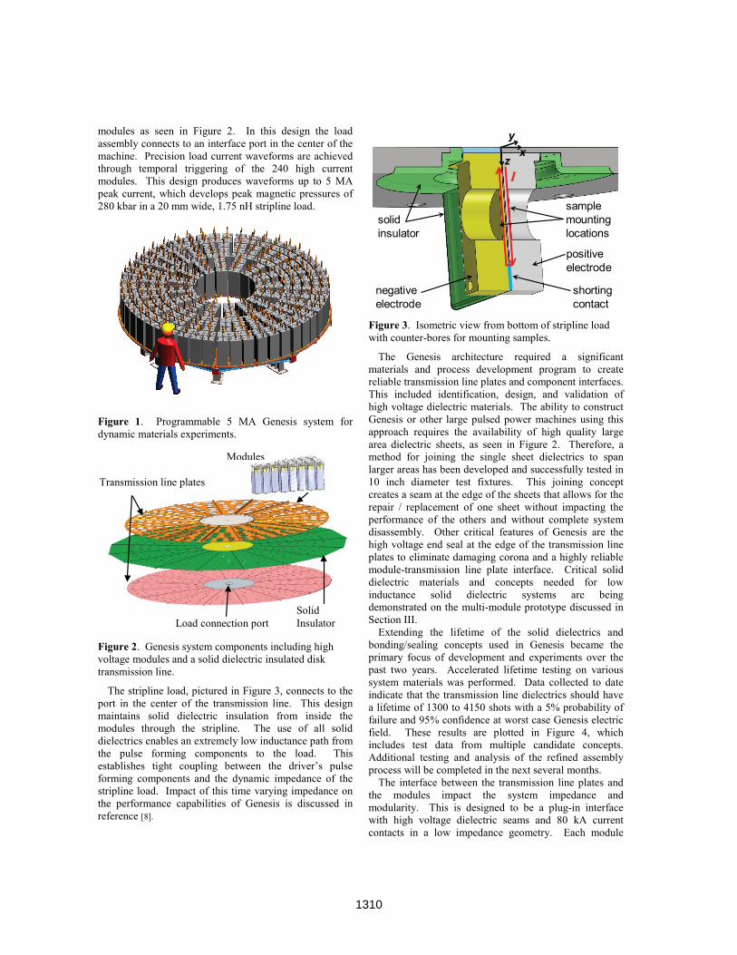
modules as seen in Figure 2. In this design the load assembly connects to an interface port in the center of the machine. Precision load current waveforms are achieved through temporal triggering of the 240 high current modules. This design produces waveforms up to 5 MA peak current, which develops peak magnetic pressures of 280 kbar in a 20 mm wide, 1.75 nH stripline load.
Figure 1. Programmable 5 MA Genesis system for dynamic materials experiments.
Figure 2. Genesis system components including high voltage modules and a solid dielectric insulated disk transmission line.
The stripline load, pictured in Figure 3, connects to the port in the center of the transmission line. This design maintains solid dielectric insulation from inside the modules through the stripline. The use of all solid dielectrics enables an extremely low inductance path from the pulse forming components to the load. This establishes tight coupling between the driver’s pulse forming components and the dynamic impedance of the stripline load. Impact of this time varying impedance on the performance capabilities of Genesis is discussed in reference [8].
Figure 3. Isometric view from bottom of stripline load with counter-bores for mounting samples.
The Genesis architecture required a significant materials and process development program to create reliable transmission line plates and component interfaces. This included identification, design, and validation of high voltage dielectric materials. The ability to construct Genesis or other large pulsed power machines using this approach requires the availability of high quality large area dielectric sheets, as seen in Figure 2. Therefore, a method for joining the single sheet dielectrics to span larger areas has been developed and successfully tested in 10 inch diameter test fixtures. This joining concept creates a seam at the edge of the sheets that allows for the repair / replacement of one sheet without impacting the performance of the others and without complete system disassembly. Other critical features of Genesis are the high voltage end seal at the edge of the transmission line plates to eliminate damaging corona and a highly reliable module-transmission line plate interface. Critical solid dielectric materials and concepts needed for low inductance solid dielectric systems are being demonstrated on the multi-module prototype discussed in Section III.
Extending the lifetime of the solid dielectrics and bonding/sealing concepts used in Genesis became the primary focus of development and experiments over the past two years. Accelerated lifetime testing on various system materials was performed. Data collected to date indicate that the transmission line dielectrics should have a lifetime of 1300 to 4150 shots with a 5% probability of failure and 95% confidence at worst case Genesis electric field. These results are plotted in Figure 4, which includes test data from multiple candidate concepts. Additional testing and analysis of the refined assembly process will be completed in the next several months.
The interface between the transmission line plates and the modules impact the system impedance and modularity. This is designed to be a plug-in interface with high voltage dielectric seams and 80 kA current contacts in a low impedance geometry. Each module
solid insulator
positive electrode
negative electrode
sample mounting locations
shorting contact
xy
zI
Modules
Solid Insulator
Transmission line plates
Load connection port
1310
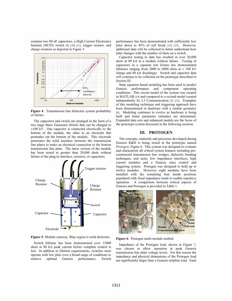
contains two 80 nF capacitors, a High Current Electronics Institute (HCEI) switch [9] [10] [11], trigger resistor, and charge resistors as depicted in Figure 5.
Figure 4. Transmission line dielectric system probability of failure.
The capacitors and switch are arranged in the form of a two stage Marx Generator (brick) that can be charged to ±100 kV. One capacitor is connected electrically to the bottom of the module, the other to an electrode that protrudes out the bottom of the module. This electrode penetrates the solid insulator between the transmission line plates to make an electrical connection to the bottom transmission line plate. The latest version of the module has been tested to greater than 20,000 shots without failure of the plug-in interface, resistors, or capacitors.
Figure 5. Module cutaway. Blue region is solid dielectric.
Switch lifetime has been demonstrated over 13000 shots at 80 kA peak current before complete control is lost. In addition to lifetime requirements, switches must operate with low jitter over a broad range of conditions to achieve optimal Genesis performance. Switch
performance has been demonstrated with sufficiently low jitter down to 45% of self break [12] [13]. However, additional data will be collected to better understand how jitter changes with the number of shots on a switch.
Capacitor testing to date has resulted in over 20,000 shots at 80 kA in a module without failure. Testing of capacitors in a separate test fixture has demonstrated lifetimes ranging from 2000 to 6000 shots at ± 100 kV charge and 80 kA discharges. Switch and capacitor data will continue to be collected on the prototype described in Section III.
State equation based modeling has been used to predict Genesis performance and component operating conditions. This circuit model of the system was created in MATLAB [14] and compared to a second model created independently by L3 Communication [5] [15]. Examples of this modeling technique and triggering approach have been demonstrated in hardware with a similar geometry [6]. Modeling continues to evolve as hardware is being built and better parameter estimates are determined. Expanded data sets and enhanced models are the focus of the prototype system discussed in the following sections.
III. PROTOGEN
The concepts, materials and processes developed during Genesis R&D is being tested in the prototype named Protogen, Figure 6. This system was designed to evaluate and characterize all critical system features including pre-constructed transmission line wedges, dielectric bonding techniques, end seals, low impedance interfaces, high current modules and a Genesis class control and triggering system. Protogen was designed to hold up to twelve modules. However, eight modules have been installed with the remaining four inside positions populated with fixed impedance loads to enable repetitive operation. A comparison between critical aspects of Genesis and Protogen is provided in Table 1.
Figure 6. Protogen multi-module testbed.
Impedance of the Protogen load, shown in Figure 7, was chosen to allow operation at peak Genesis transmission line plate voltage levels. For this reason the impedance and physical dimensions of the Protogen load are significantly larger than a Genesis stripline load. Each
100001000100
0.990.90.80.70.60.50.40.30.2
0.10.050.030.020.01
0.001
Shots on insulator
Pro
ba
bil
ity
Trigger resistor
Switch
Capacitor
Charge Resistor
Electrode
Capacitor
Charge Resistor
Module Transmission line plate
Load Seam
End seal
95% confidence interval
- +
+ -
1311
load is designed to be 1.5 Ω, 160 nH, and install in the same port as the high current modules.
Table 1. Genesis and 8 module Protogen comparison.
Genesis2
Protogen3,4,5
Ratio (%)
Modules 240 8 3.3 Dielectric area 12.9 m2 1.3 m2 10.1 Seam length 41.2 m 4.7 m 11.4
End seal length 15.4 m 5.8 m 37.7 Peak module current1 80 kA 50 kA 62.5
Peak load current1 4 MA 221 kA 5.5 Peak transmission line
voltage1 92 kV 100 kV 108.9 1 Based on simulation. 2 Operating point for 1200 shot lifetime, see the dynamic load data in
Figures 14-16 of [8]. 3 Data in this column represents the present Protogen configuration.
Installation of twelve modules and a Genesis load would enable a peak load current2 of 871 kA.
4 Operating point chosen to exceed mean peak stresses of Genesis, given a rotational firing scheme from shot to shot.
5 Based on the waveforms chosen for accelerated lifetime testing of the dielectrics.
Dielectrics between the Protogen transmission line plates are assembled using the same materials and processed defined for Genesis. This allows testing of larger area samples for the first time in an integrated configuration. Testing of seams prior to this experiment was conducted on small fixtures that allowed rapid prototyping to identify optimal materials and techniques.
Figure 7. Protogen load for repetitive operation.
Module interfaces implemented in Protogen are identical to the Genesis design. With the installation of eight modules and four loads a total of twelve interfaces will be simultaneously tested. Testing will occur at Genesis-level electric field stresses but at lower peak current due to the larger load impedance required to reach Genesis transmission line voltage levels. Data from the Protogen experiments will be folded back into the existing database to refine the reliability and lifetime analysis as well as the model accuracy.
IV. PROTOGEN CIRCUIT MODEL
Performance of Protogen is predicted with a lumped element state equation based circuit model. This model uses the same modeling elements as the Genesis model described in reference [5]. The Protogen circuit diagram is overlaid on top view of a Protogen diagram in Figure 8.
Figure 8. Protogen circuit model with submodels at the nodes, module and load locations.
A simplified transmission line model was used to simulate current flow along the plates, while the parasitics through the dielectric are lumped at the nodes in Figure 8. Loads are represented by RL circuits and the modules by RLC circuits with a switch. Within each module, a time varying resistance is used to capture the dynamic behavior of the high voltage switch.
The switch model [16], which is an extension of the spark channel work in [17], uses a time varying resistance to describe the energy loss in each switch. In this model the radius of the spark channel, 𝑎, is a function of the current flowing through the channel as defined by
𝑎 = 4
𝜋2𝜌0𝜉𝜎13
𝐼2 3𝑡
0𝑑𝑡 (1)
where I is the magnitude of the current in the channel, 𝜌𝑜 is the gas density, 𝜎 is the conductivity of the gas, and 𝜉 is set to a constant value of 4.5 as defined in [16]. The resistance of a single channel
CVR
Load Resistors
Module base / interface
1312

𝑅𝑐ℎ𝑎𝑛𝑛𝑒𝑙 =𝐿𝑐𝑚𝜎 𝜋 𝑎2
(2)
is then based on the radius, where 𝐿𝑐𝑚 is the channel length. From Rchannel the total HCEI switch resistance is calculated as
𝑅𝑠𝑤𝑖𝑡𝑐ℎ =𝑅𝑐ℎ𝑎𝑛𝑛𝑒𝑙
(𝑛𝑐ℎ𝑎𝑛𝑛𝑒𝑙𝑠)1 3 (3)
where nchannels is the total number of spark channels formed.
All of the parameters in the switch model are predefined except for the number of channels. To determine how many channels form over a range of operating conditions, self break data from an HCEI switch (modified for Genesis) was used. This data was collected from a switch installed in a brick configuration but external to a module. A Genetic Optimization (GO) routine [18] was used to determine the fixed R, L, and C in the circuit in addition to the nchannels for the switch model at a given operating condition. Parameters were fitted to all six waveforms simultaneously with the fixed R, L, and C forced to be identical for all waveforms, see Figure 9. Table 2 contains the operating conditions and the number of channels estimated by the GO. It is expected that there is a certain probability for any given channel to form, therefore the number of channels formed each time the switch is operated is expected to be stochastic. Repeating the above experiment six times at the operating conditions for shot 149 resulted in a mean of 2.4 channels with a standard deviation of 0.4. The overall effect of this range of channel values on currents was investigated in a simulated example, which resulted in an average peak current of 71.96 kA with a standard deviation of 0.36 kA.
Research by Woodworth [11] supports these results. In his publication, the six spark gaps of the HCEI switch (referred to as the Russian switch) are identified along with the switch operation. This includes the method in which the number of channels can vary from gap to gap, and how the conductivity of each channel is not necessarily identical. Figures 22 – 24 in [11] indicate how the effective number of channels across the entire switch would not necessarily be an integer value. Moreover, it is unlikely that the number, conductivity, and location of the channels formed will remain constant from shot to shot, making 𝑛𝑐ℎ𝑎𝑛𝑛𝑒𝑙𝑠 change in a manner difficult to predict.
Impact to the Protogen simulation, when including the non-ideal switch model, is evident in Figure 10. In this plot, results are provided with and without the time varying switch resistance. The initial capacitor charge voltages (190 kV) and the trigger times were the same for both simulations. The simulation with the time varying resistance had the switch pressure set at 16.5 psig and the number of channels to 2.4. It was found that the non-ideal switch model reduced the peak load currents and the transmission line voltages by 7.7% and 9.9% respectively. The rise time and damping of the waveforms were affected as well.
Figure 9. Six simulated currents (green) fit to six measured currents (black). See Table 2.
Table 2. Estimated number of channels at different operating conditions.1
Shot Number
Voltage (kV)
Switch Pressure (psig)
𝒏𝒄𝒉𝒂𝒏𝒏𝒆𝒍𝒔
63 148 9.0 2.5 98 159 11.0 2.6
103 168 12.5 4.0 123 182 15.0 4.1 149 191 16.5 3.9 173 196 18.0 4.8
1 Self break data taken from switch number 17 on March 11, 2011.
Modeling and simulation techniques will continue to evolve as new data becomes available from the Protogen experiments. In addition, new triggered switch data will be collected to refine the HCEI switch model. Modeling advances with Protogen will increase the ability to design and predict the performance of other Genesis-like systems.
Figure 10. Protogen Ideal Switch (green) vs. non-ideal switch model (black).
ideal
ideal
Shot 63
Shot 98
Shot 103
Shot 123
Shot 149
Shot 173
ideal
1313
V. CONCLUSION
Critical solid dielectric system concepts, materials, and construction processes have been developed for the Genesis system. Advanced pulse shaping techniques have been developed and analyzed and the basic performance of Genesis components has been demonstrated. Advanced switch characterization continues to improve the capability of Genesis modeling to predict system performance.
The focus of Genesis R&D now turns to a demonstration of these concepts on a scaled testbed called Protogen. Protogen will allow system level reliability studies and a comparison of Genesis modeling techniques to hardware system performance. Protogen can be used to effectively demonstrate all the key concepts required for a Genesis-class system or other systems requiring precision control of multi-MA current into low inductance loads.
The goal of the Genesis system is to offer extreme user flexibility in a compact platform. If reduced operational flexibility is desired, Genesis concepts can be used to develop lower complexity, highly efficient multi-MA driver platforms.
VI. ACKNOWLEDGEMENTS
The authors would like to thank: H.D. Anderson, H.L. Brown, M.L. Horry, M.D. Knudson, M.J. Madlener, G. Neau, K. Prestwich, V. Romero, S.D. Sudhoff, and R. White for their support, insight, and valuable discussions regarding this project. The authors also gratefully acknowledge valuable contributions from their colleagues at Sandia National Laboratories, Raytheon Ktech Corporation, EG&G, L-3 Communications, and Purdue University.
VII. REFERENCES
[1] C. A. Hall, “Isentropic compression experiments on the Sandia Z accelerator,” Physics of Plasmas, Vol. 7, No. 5, pp. 2069-2075, May 2000.
[2] J.P. Davis, et al., “Magnetically driven isentropic compression to multimegabar pressures using shaped current pulses on the Z accelerator,” Physics of Plasmas, vol. 12, no. 5, 2005.
[3] J.-P. Davis, et al., “Magnetically driven isentropic compression to multimegabar pressures using shaped current pulses on the Z accelerator,” Phys. Plasmas, vol. 12, no. 5, p. 056 310, May 2005.
[4] T. Ao, et al., “A compact strip-line pulsed power generator for isentropic compression experiments,” Review of Scientific Instruments, 79, 013903, 2008.
[5] S.F. Glover, et al., “Genesis: A 5 MA programmable pulsed power driver for isentropic compression experiments,” IEEE Transactions on Plasma Science, Vol. 38, No. 1, pp. 2620-2626, October, 2010.
[6] S. F. Glover, et al., “Genetic optimization for pulsed power system configuration,” IEEE Trans. Plasma Sci., vol. 37, no. 2, pp. 339–346, Feb. 2009.
[7] SolidWorks 3D CAD Software, Dassault Systèms SolidWorks Corp., 300 Baker Avenue, Concord, MA 01742, USA, www.solidworks.com.
[8] S.F. Glover, et al., “Impact of Time Varying Loads on the Programmable Pulsed Power Driver Called Genesis,” 18th IEEE International Pulsed Power Conference, June 2011.
[9] B.M. Kovalchuk, et al. “Multi gap switch for Marx generators,” Pulsed Power Plasma Science Conference, pp. 1739-1742, June, 2001.
[10] M.G. Mazarakis, et al., "High current, 0.5 MA, fast, 100ns linear transformer driver experiments,” Physical Review Special Topics – Accelerators and Beams, 12, 050401 2009.
[11] J. R. Woodworth, et al., “Low-inductance gas switches for linear transformer drivers,” Physical Review Special Topics – Accelerators and Beams 12, 060401, 2009.
[12] S.F. Glover, et al., “Pulsed and DC charged PCSS based trigger generators,” IEEE Transactions on Plasma Science, Vol. 38, No. 1, pp. 2701-2707, October, 2010.
[13] Jane Lehr, et al., “Evaluation of Spark Gap Switches Operated at Low Percent of Self Break Voltage,” presentation at the 17th IEEE Pulsed Power Conference, June 2009.
[14] MATLAB The Language of Technical Computing, The MathWorks, Inc., 3 Apple Hill Drive, Natick, MA 01760-2098 USA, [email protected].
[15] G. Neau, L3 Communications, 4855 Ruffner St., Suite A, San Diego, CA 92111.
[16] T. H. Martin, et al., “Energy Losses in Switches,” 9th IEEE International Pulsed Power Conference, pp. 463-470, June 1993.
[17] S. I. Braginskii, “Theory of the Development of a Spark Channel,’’ JETP, Vol. 34 (7), No. 6, pp. 1068, December 1958.
[18] S.D. Sudhoff and Y. Lee, “Energy Systems Analysis Consortium (ESAC) Genetic Optimization System Engineering Tool, v. 2.2 Manual,” School of Electrical and Computer Engineering., Purdue Univ., West Lafayette, IN., 47907. [email protected]
1314


![-worst case delay lw) › courses › comparch › 2015 › files › fall... · 2016-10-04 · cslab@ntua 2015-2016 13 5. Memory read completion (write back step) Reg[IR[20-16]]](https://static.fdocument.org/doc/165x107/5f28f44b0fef8764c4419e5e/worst-case-delay-lw-a-courses-a-comparch-a-2015-a-files-a-fall-2016-10-04.jpg)