St th f M t i lStrength of Materials - Avant-Garde Engineering · St th f M t i lStrength of...
64
P.E. Civil Exam Review: St th fM t il Strength of Materials J.P. Mohsen Email:jpm@louisville.edu
Transcript of St th f M t i lStrength of Materials - Avant-Garde Engineering · St th f M t i lStrength of...
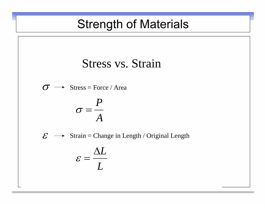
Strength of Materials
Stress vs StrainStress vs. Strain
Stress = Force / Area Stress Force / Area
AP
Strain = Change in Length / Original LengthA
LL
L
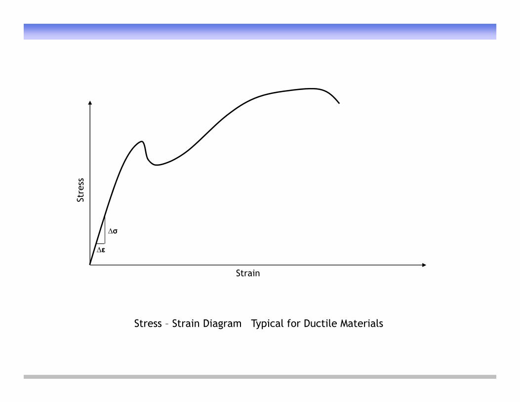
Stre
ss
Strain
∆σ
∆ε
Stress – Strain Diagram Typical for Ductile Materialsg yp
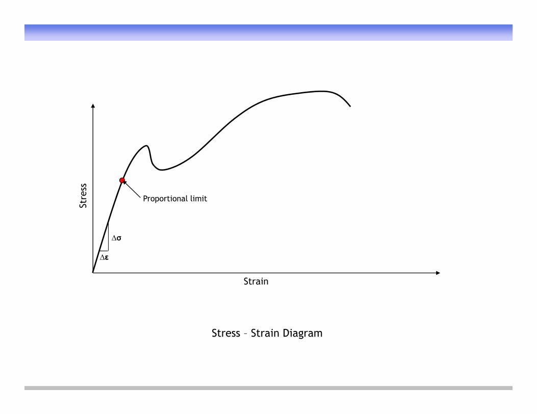
Stre
ss
Proportional limit
Strain
∆σ
∆ε
Stress – Strain Diagramg
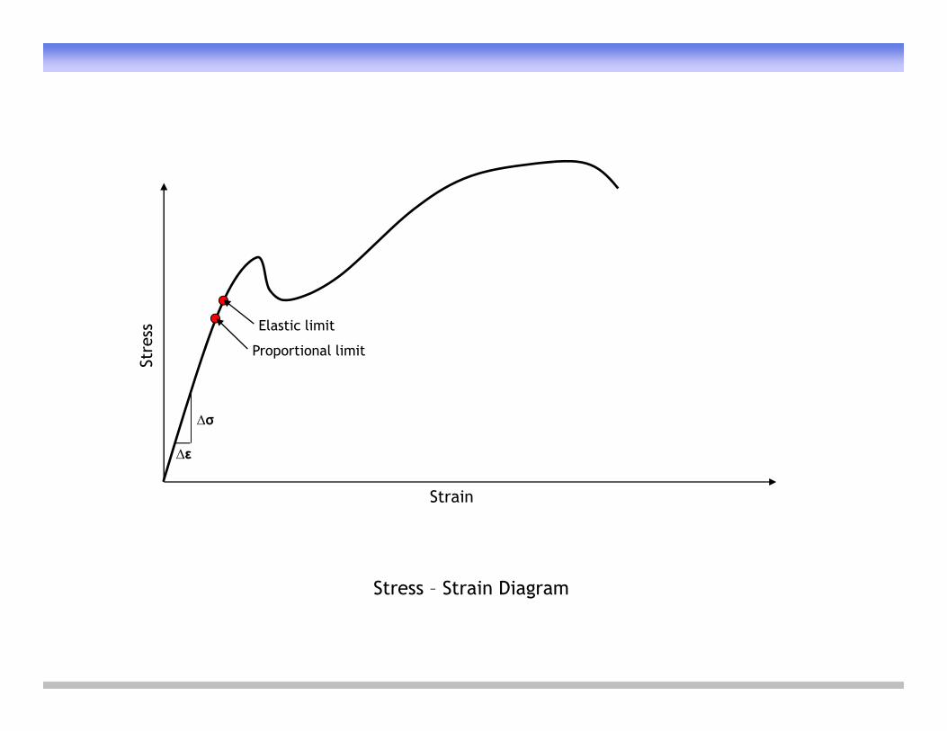
Stre
ss
Proportional limit
Elastic limit
Strain
∆σ
∆ε
Stress – Strain Diagramg
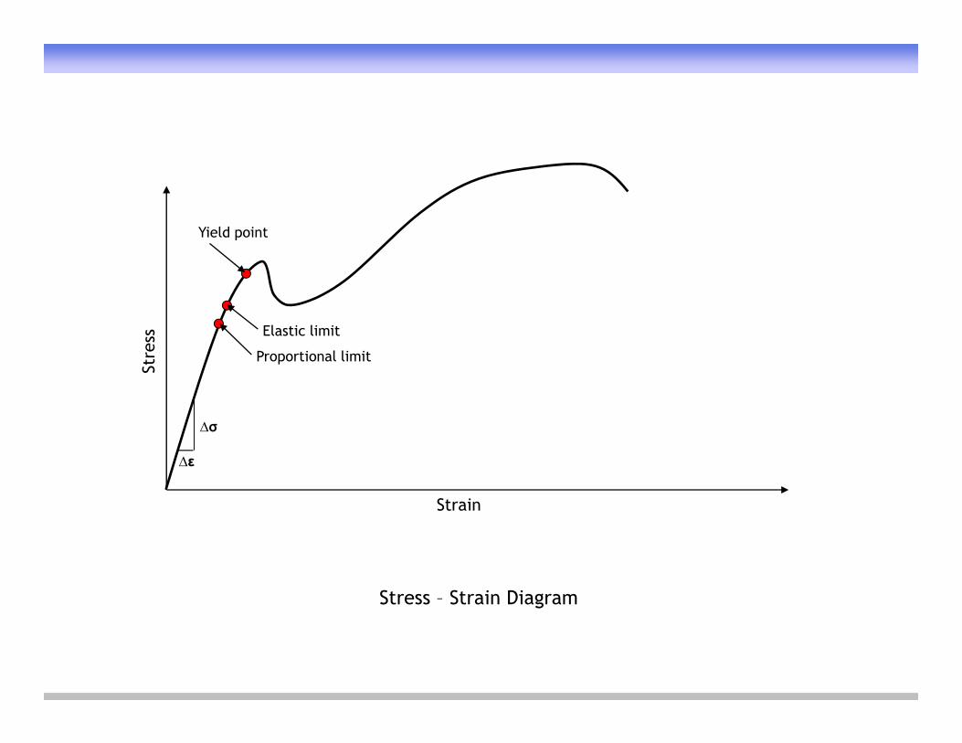
Yield pointYield point
Stre
ss
Proportional limit
Elastic limit
Strain
∆σ
∆ε
Stress – Strain Diagramg
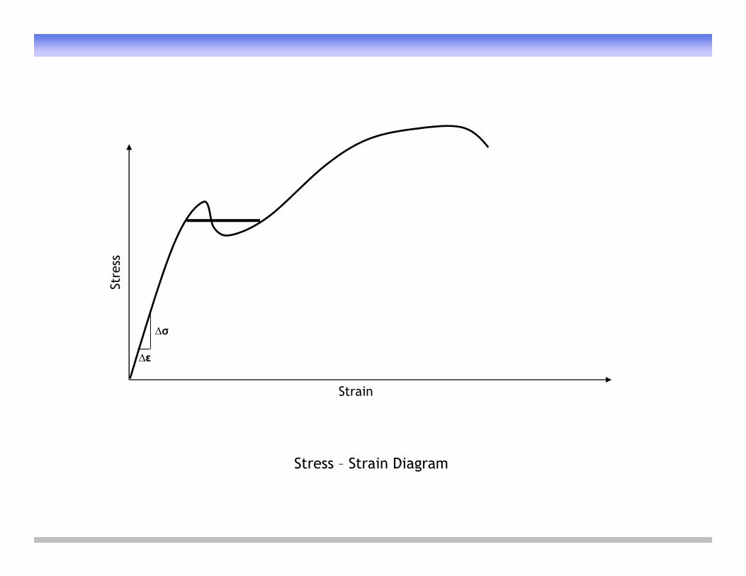
Stre
ss
Strain
∆σ
∆ε
Stress – Strain Diagramg
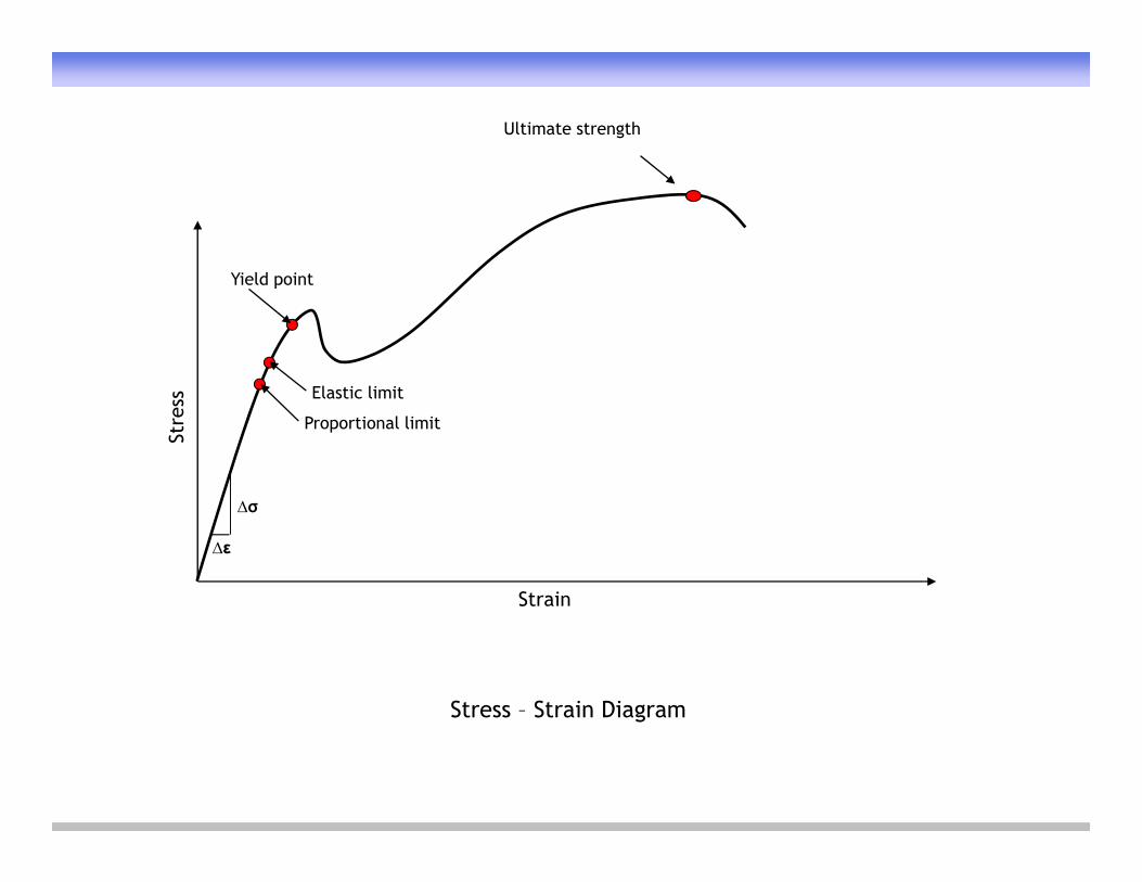
Ultimate strength
Yi ld i tYield point
Stre
ss
Proportional limit
Elastic limit
Strain
∆σ
∆ε
Stress – Strain Diagramg
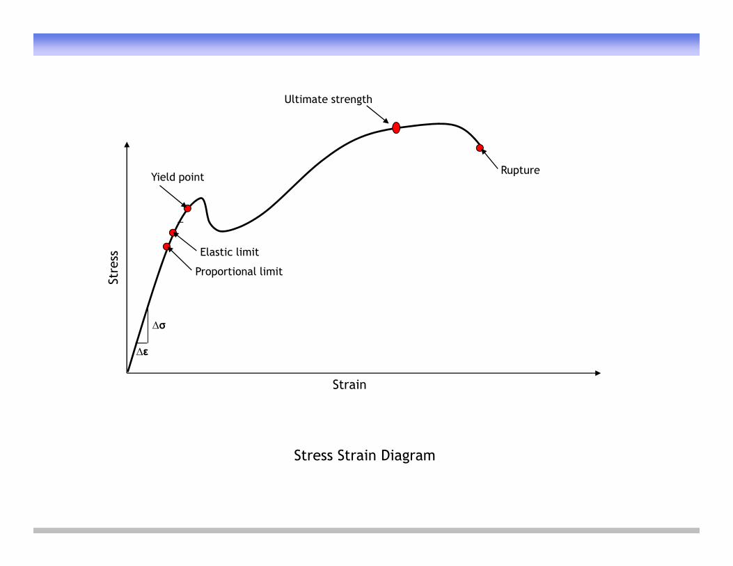
Ultimate strength
Yield point
g
RuptureYield point
p
Stre
ss
Proportional limit
Elastic limit
Strain
∆σ
∆ε
Stress Strain Diagramg
Yield point
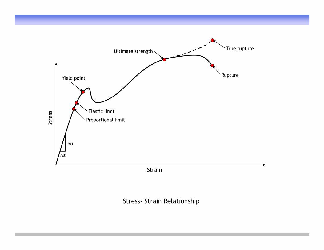
Ultimate strength
Rupture
True rupture
Yield pointp
Stre
ss
Proportional limit
Elastic limit
Strain
∆σ
∆ε
Stress- Strain Relationshipp
Stre
ss
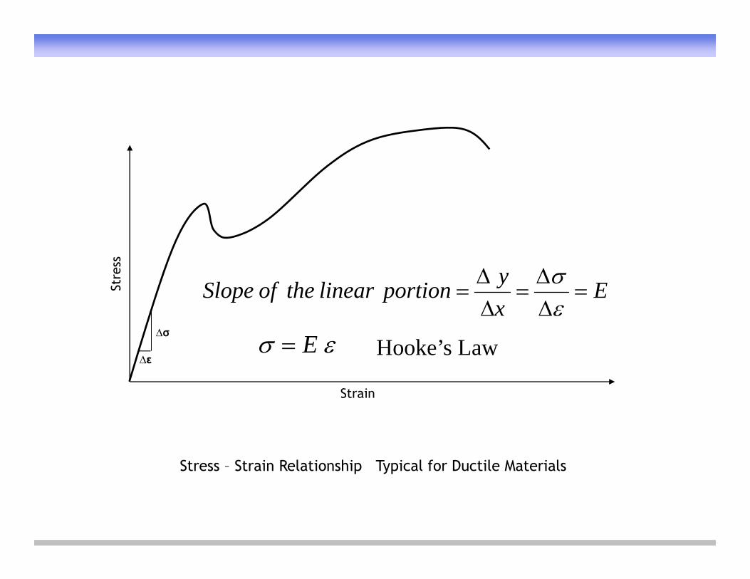
ExyportionlineartheofSlope
Strain
∆σ
∆εHooke’s Law E
Stress – Strain Relationship Typical for Ductile Materialsp yp
High strength
ress
M d l f ress
ress
High strength
Fracture
Hightoughness
Str
S
Modulus of resilience
Str
S
Str
St i
Toughnesstoughness
(a)
Strain
(b)
Strain
(c)
Strain
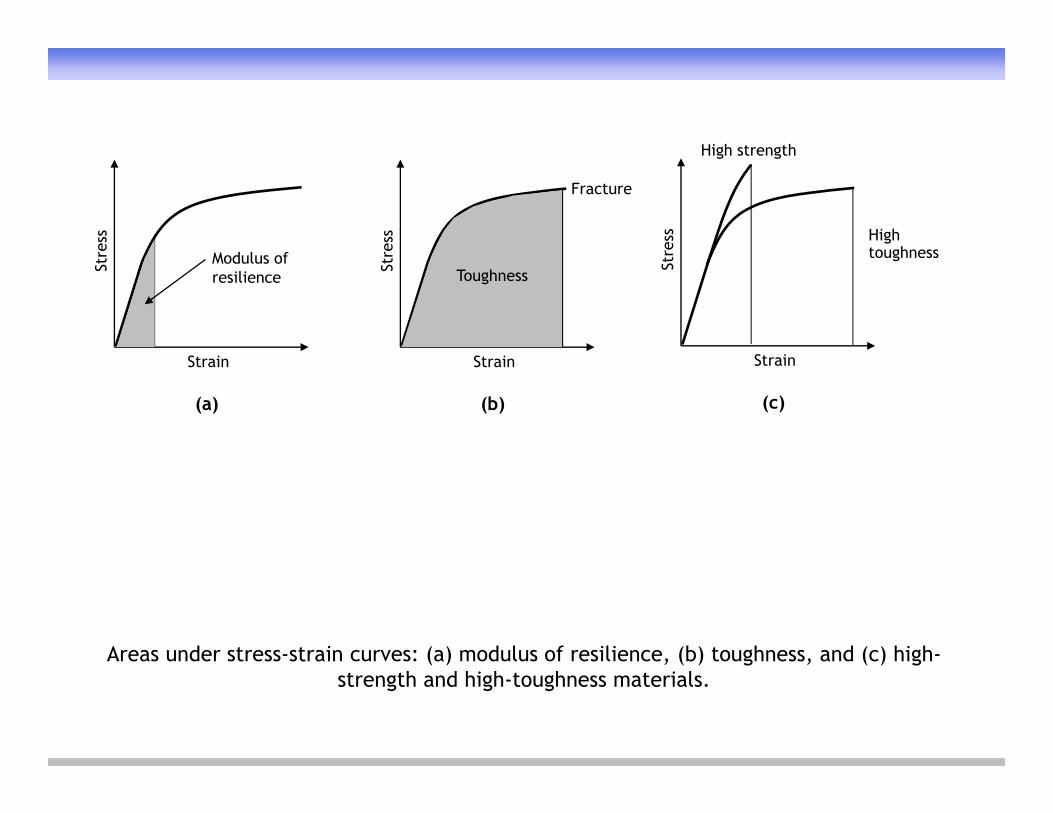
Areas under stress-strain curves: (a) modulus of resilience, (b) toughness, and (c) high-( ) , ( ) g , ( ) gstrength and high-toughness materials.
Elastic limitSt
ress
0.2% offset yield strength
Stre
ss
0.5% extension yield strength
S
Strain, %
Proportional limit
S
Strain, %
(a)
0.2%
(b)
0.5%
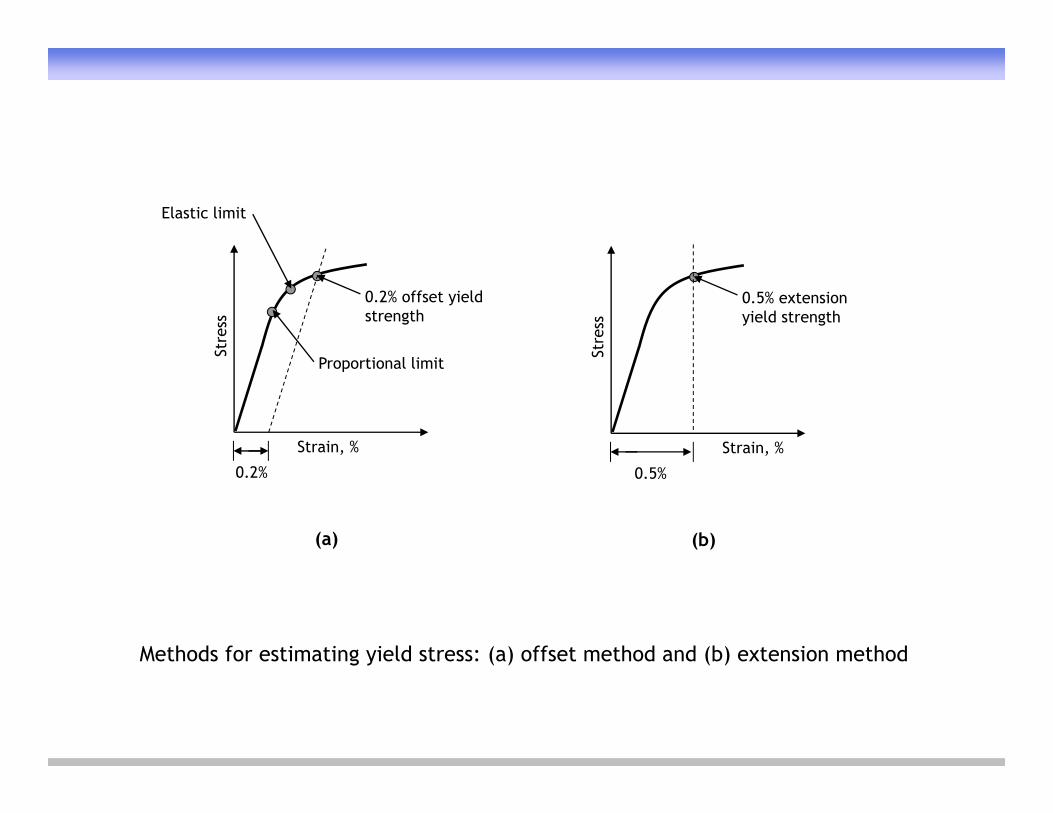
Methods for estimating yield stress: (a) offset method and (b) extension methodg y ( ) ( )
Tangent modulus
Initial tangent modulus
Chord modulus
Stre
ss
Strain
Secant modulus
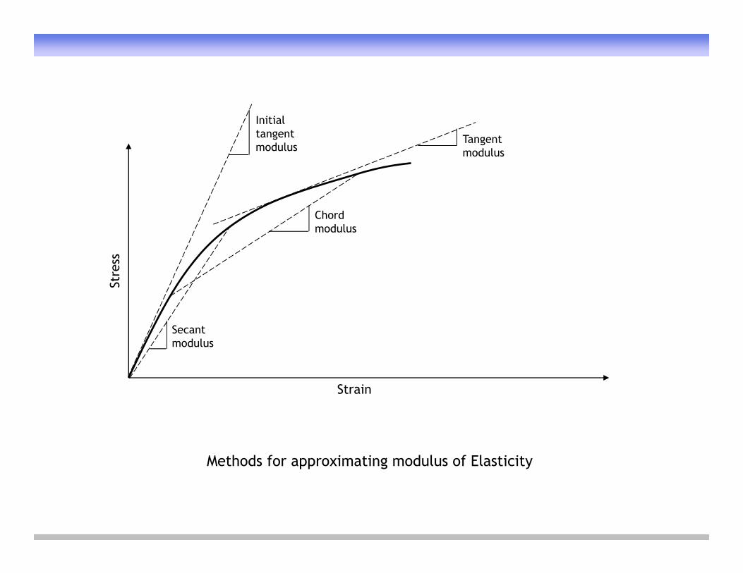
Methods for approximating modulus of Elasticitypp g y
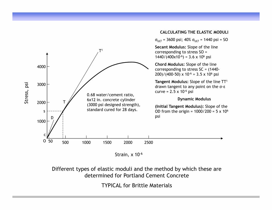
CALCULATING THE ELASTIC MODULI
σ 3600 psi; 40% σ 1440 psi SO
4000
T1
σULT = 3600 psi; 40% σULT = 1440 psi = SO
Secant Modulus: Slope of the line corresponding to stress SO = 1440/(400x10-6) = 3.6 x 10⁶ psi
Chord Modulus: Slope of the line
s, p
si 3000
4000 Chord Modulus: Slope of the line corresponding to stress SC = (1440-200)/(400-50) x 10-6 = 3.5 x 10⁶ psi
Tangent Modulus: Slope of the line TT1
drawn tangent to any point on the σ-εcurve = 2 5 x 10⁻⁶ psi
Stre
ss
2000
D
T
0.68 water/cement ratio, 6x12 in. concrete cylinder (3000 psi designed strength), standard cured for 28 days.s
curve = 2.5 x 10 psi
Dynamic Modulus
(Initial Tangent Modulus): Slope of the OD from the origin = 1000/200 = 5 x 10⁶
psi1000
D
O 500 1000 1500 2000 2500
c
50
p
Different types of elastic moduli and the method by which these are
Strain, x 10-6
yp ydetermined for Portland Cement Concrete
TYPICAL for Brittle Materials
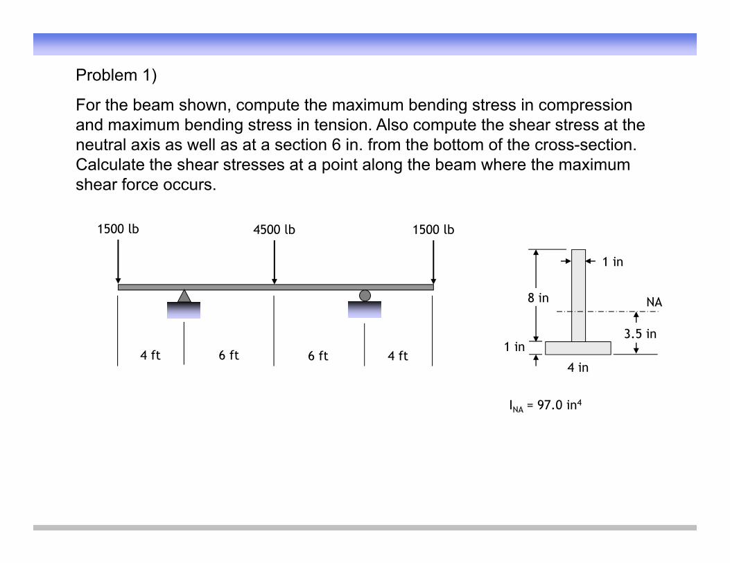
Problem 1)
For the beam shown compute the maximum bending stress in compressionFor the beam shown, compute the maximum bending stress in compression and maximum bending stress in tension. Also compute the shear stress at the neutral axis as well as at a section 6 in. from the bottom of the cross-section. Calculate the shear stresses at a point along the beam where the maximum shear force occurs.
1500 lb1500 lb 4500 lb
1 in
8 in NA
4 in
3.5 in1 in
4 ft 4 ft6 ft 6 ft
INA = 97.0 in4
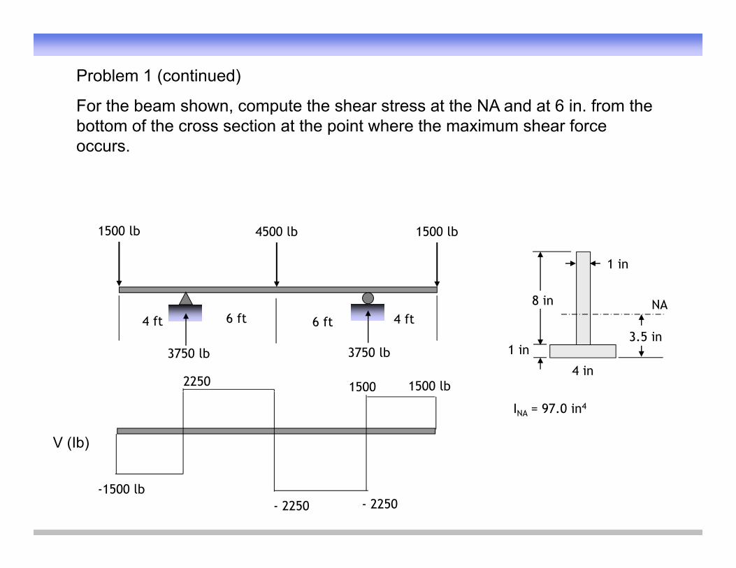
Problem 1 (continued)
For the beam shown compute the shear stress at the NA and at 6 in from theFor the beam shown, compute the shear stress at the NA and at 6 in. from the bottom of the cross section at the point where the maximum shear force occurs.
1500 lb1500 lb 4500 lb
1 in
8 in NA4 ft 4 ft6 ft 6 ft
4 in
3.5 in1 in
4 ft 4 ft6 ft 6 ft
1500 lb
3750 lb 3750 lb
2250 1500
INA = 97.0 in4
V (Ib)
-1500 lb- 2250 - 2250
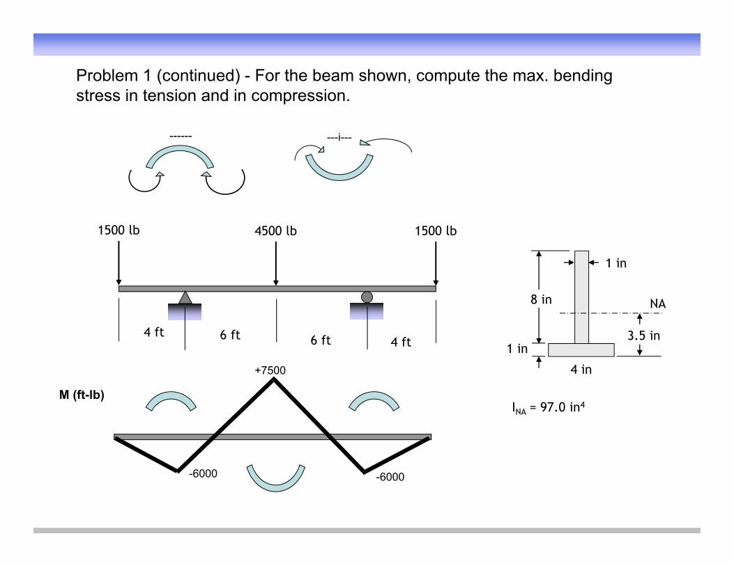
Problem 1 (continued) - For the beam shown, compute the max. bending stress in tension and in compression.
------ ---i---
1500 lb1500 lb 4500 lb
1 in
8 in NA
4 in
3.5 in1 in
4 ft4 ft6 ft 6 ft
+7500
M (ft lb)INA = 97.0 in4
M (ft-lb)
-6000 -6000
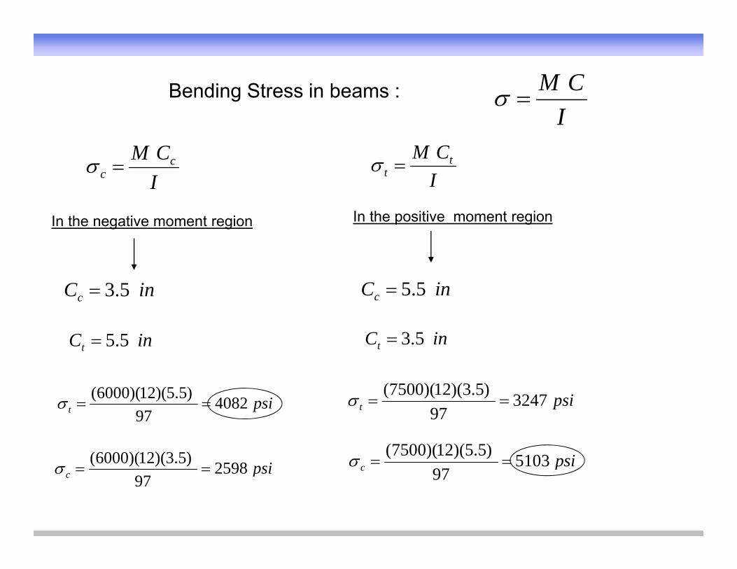
Bending Stress in beams : CM
ICM c
c
I
ICM t
t
In the negative moment region In the positive moment region
Ic I
inCc 5.3 inCc 5.5
inCt 5.5 inCt 5.3
)53)(12)(7500()55)(12)(6000( psit 324797
)5.3)(12)(7500(psit 4082
97)5.5)(12)(6000(
psi5103)5.5)(12)(7500(i2598)5.3)(12)(6000( psic 5103
97psic 2598
97))()((
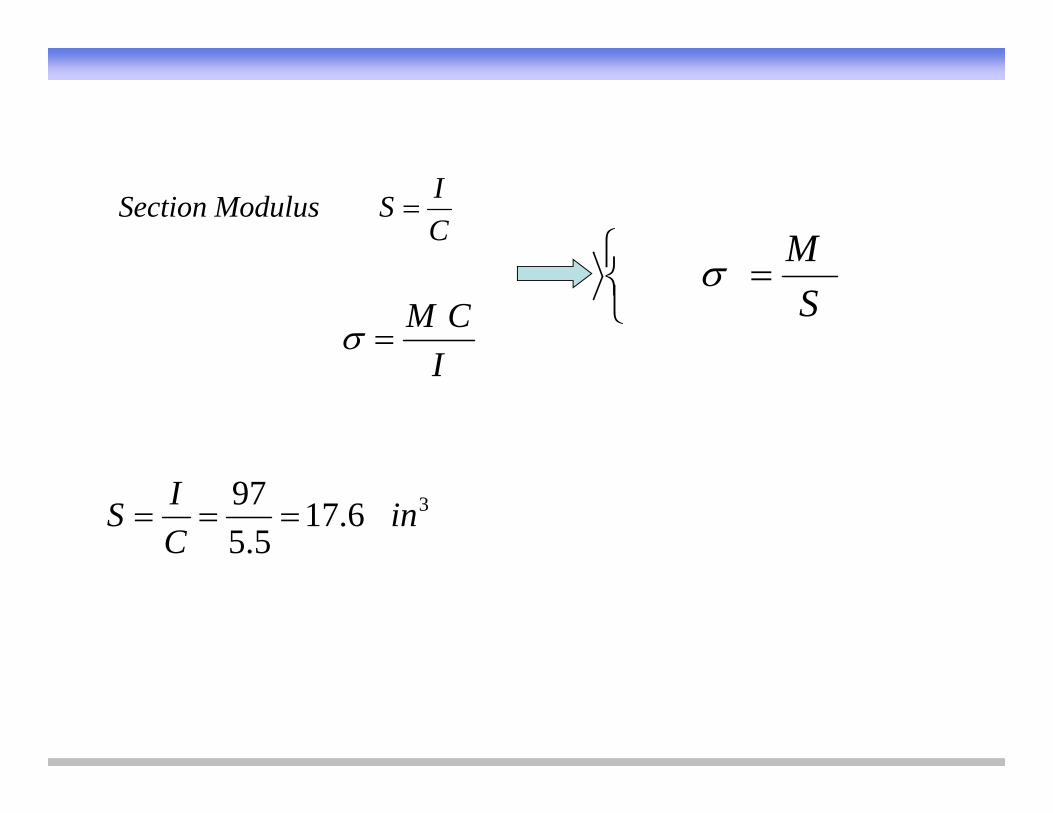
CISModulusSection
M
ICM
SM
I
36.175.5
97 inCIS

Problem 1 (continued)
For the beam shown compute the shear stress at the NA and at 6 in from theFor the beam shown, compute the shear stress at the NA and at 6 in. from the bottom of the cross section at the point where the maximum shear force occurs.
1500 lb1500 lb 4500 lb
1 in
8 in NA4 ft 4 ft6 ft 6 ft
4 in
3.5 in1 in
4 ft 4 ft6 ft 6 ft
1500 lb
3750 lb 3750 lb
2250 1500
INA = 97.0 in4
V (Ib)
-1500 lb- 2250 - 2250
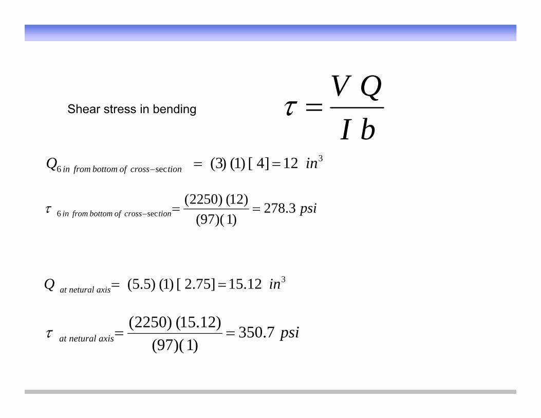
QVShear stress in bending
bIQV
bI
3sec6 12]4[)1()3( inQ tioncrossofbottomfromin
psitioncrossofbottomfromin 3.278)1)(97(
)12()2250(sec6
312.15]75.2[)1()5.5( inQ it lt 12.15]75.2[)1()5.5( inQ axisneturalat
psiaxisneturalat 7.350)1)(97(
)12.15()2250( axisneturalat )1)(97(
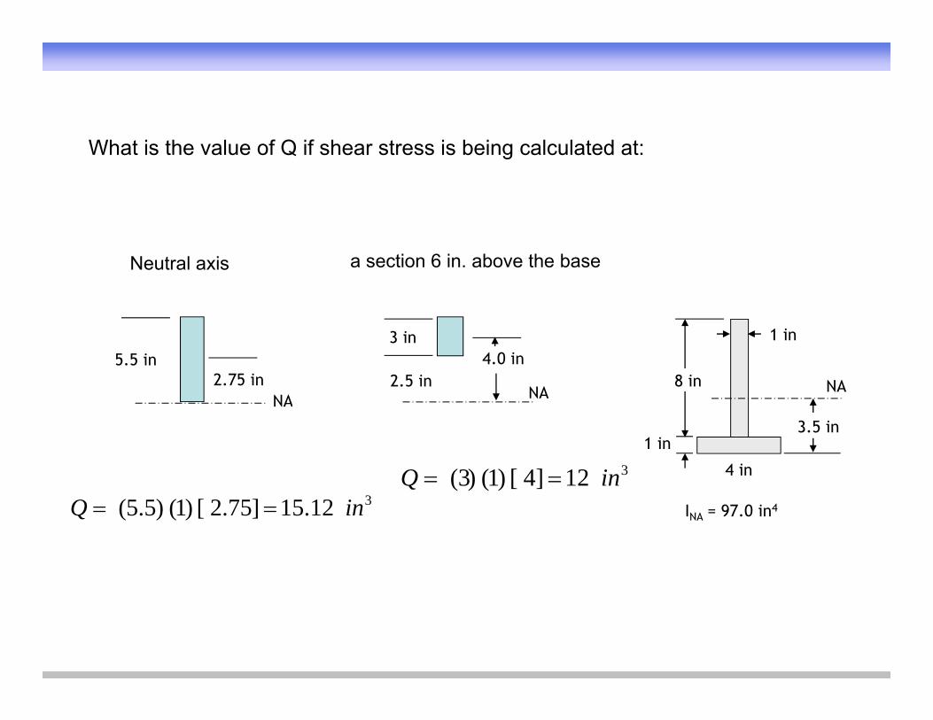
What is the value of Q if shear stress is being calculated at:
Neutral axis a section 6 in. above the base
1 in
8 in NANA
3 in4.0 in
NA2.75 in 2.5 in
5.5 in
4 in
3.5 in1 in
NA
312]4[)1()3( inQ 3
INA = 97.0 in4312.15]75.2[)1()5.5( inQ
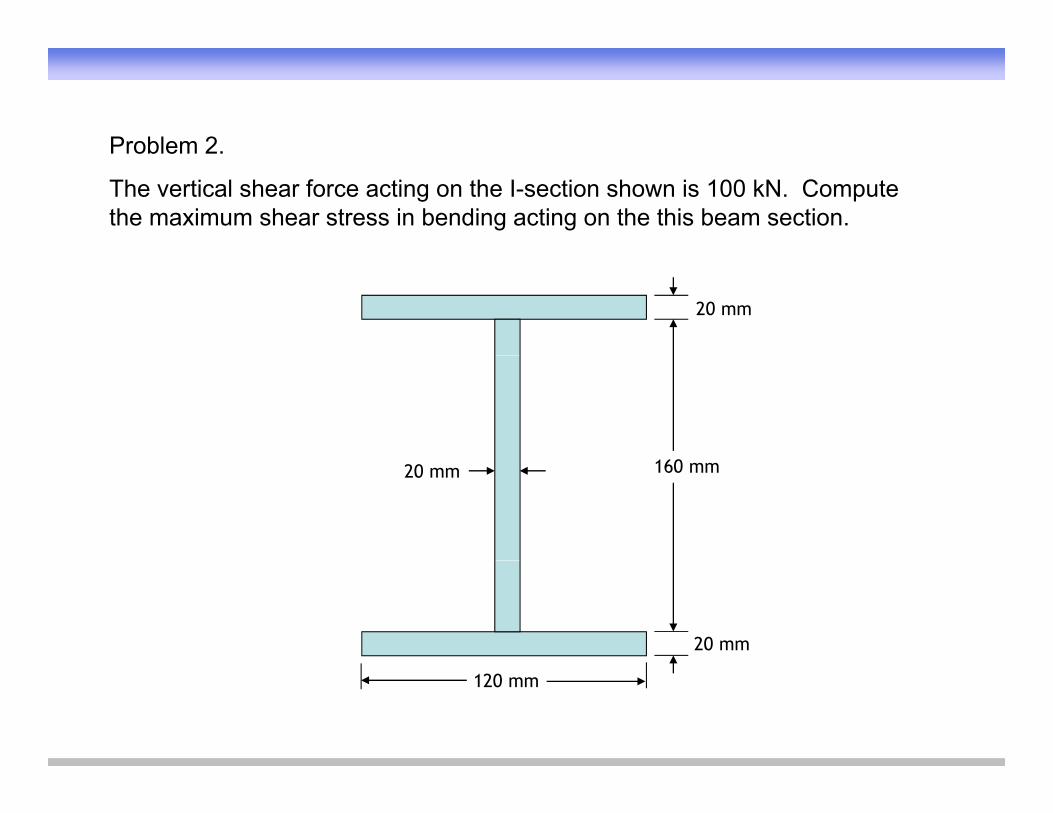
Problem 2Problem 2.
The vertical shear force acting on the I-section shown is 100 kN. Compute the maximum shear stress in bending acting on the this beam section.
20 mm
20 mm 160 mm
20 mm
120 mm
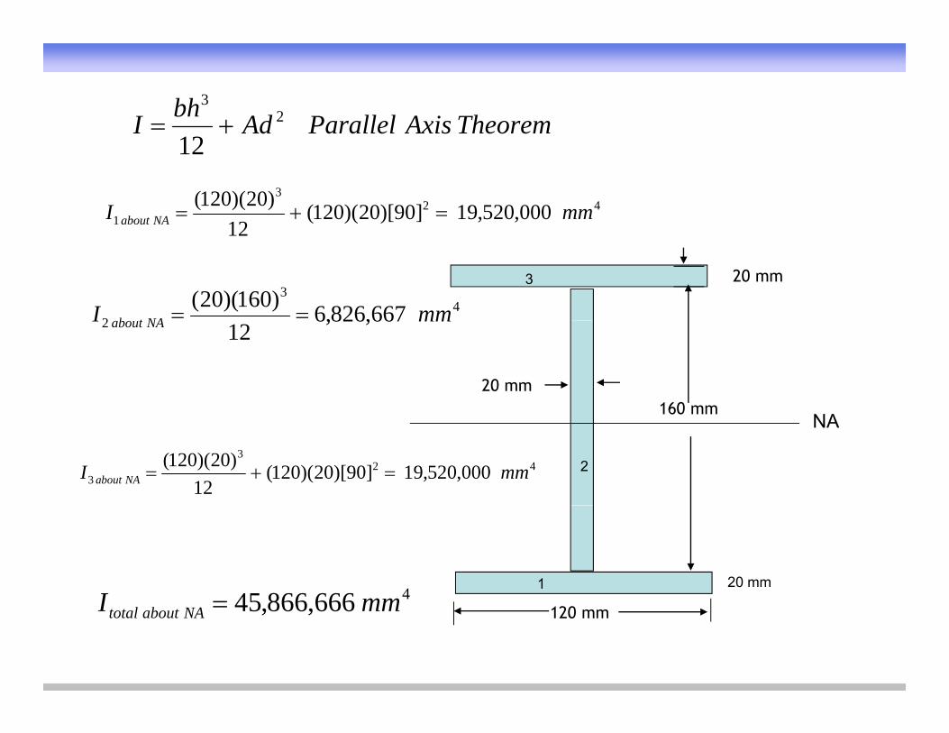
TheoremAxisParallelAdbhI 23
12
423
1 000,520,19]90)[20)(120(12
)20)(120( mmI NAabout
20 mm3
12
43
2 667,826,6)160)(20( mmI NAb t
20 mm160 mm
2 667,826,612
mmI NAabout
160 mmNA
2423
3 000,520,19]90)[20)(120(12
)20)(120( mmI NAabout
20 mm1466686645I20 mm
120 mm4666,866,45 mmI NAabouttotal
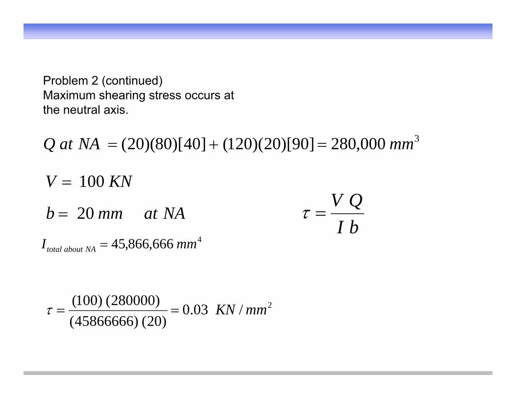
Problem 2 (continued)Maximum shearing stress occurs at the neutral axis.
3000,280]90)[20)(120(]40)[80)(20( mmNAatQ
NAatmmb 20
KNV 100
bIQV
4666,866,45 mmI NAabouttotal
bI
2/03.0)20()45866666(
)280000()100( mmKN)20()45866666(
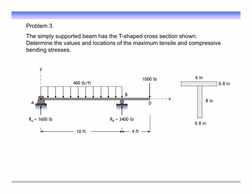
Problem 3.
The simply supported beam has the T shaped cross section shownThe simply supported beam has the T-shaped cross section shown. Determine the values and locations of the maximum tensile and compressive bending stresses.
400 lb/ft1000 lb
y
6 in0.8 in
A
B
Dx 8 in
0.8 in
10 ft 4 ft
RA = 1600 lb RB = 3400 lb0.8 in
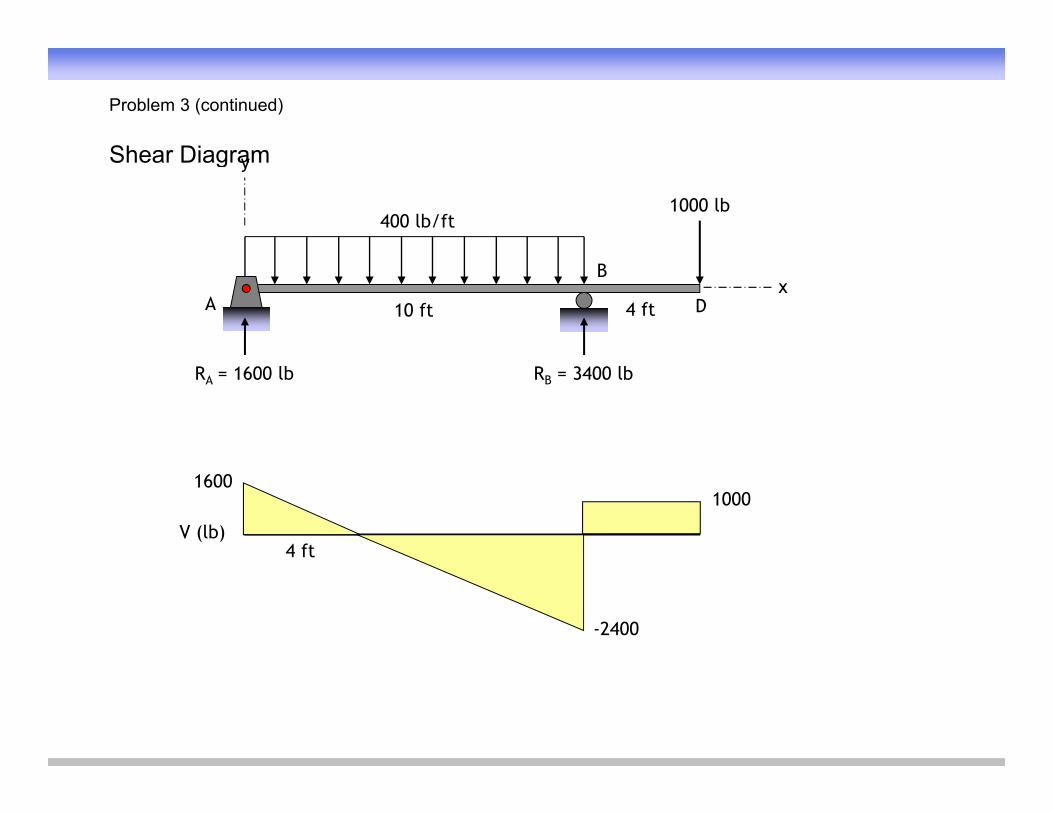
Problem 3 (continued)
Shear DiagramShear Diagram
400 lb/ft1000 lb
y
A
B
D10 ft 4 ftx
RA = 1600 lb RB = 3400 lb
16001000
4 ftV (lb)
-2400
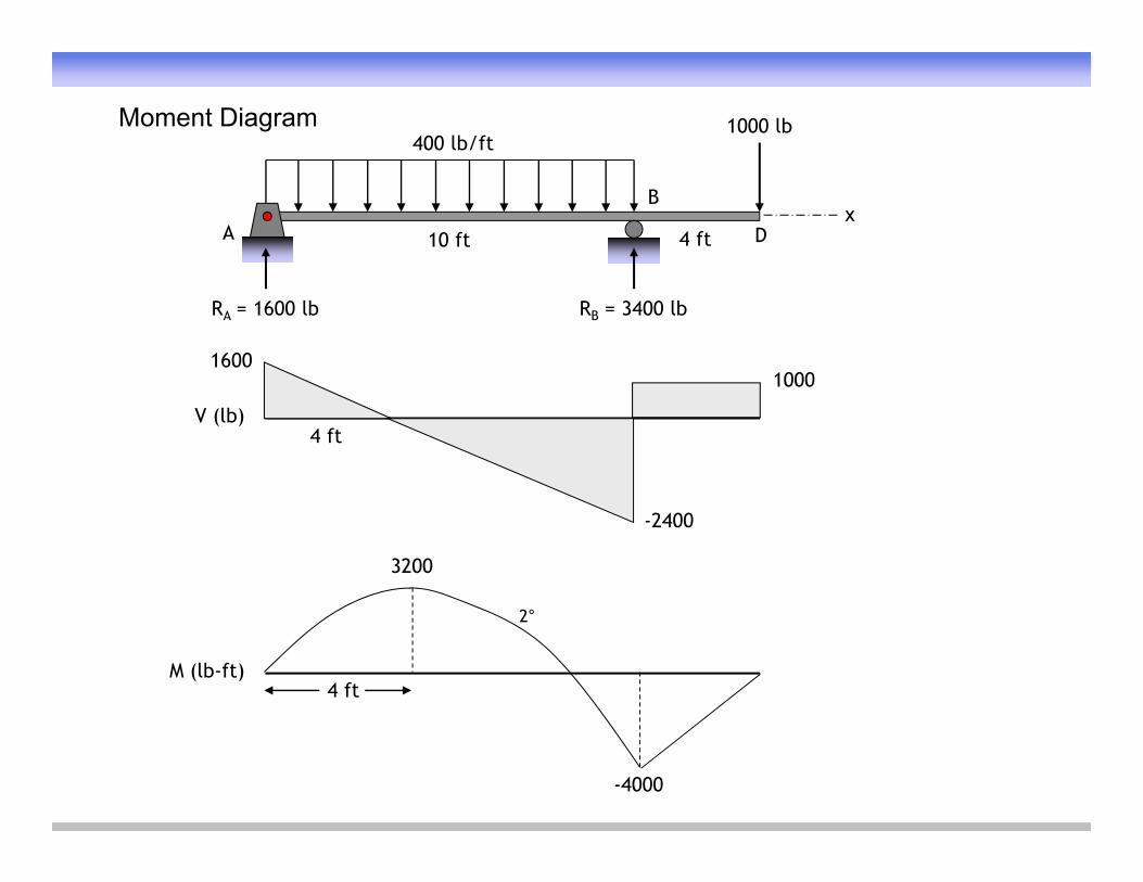
Moment Diagram400 lb/ft
1000 lb
A
B
D10 ft 4 ftx
RA = 1600 lb RB = 3400 lb
160010001000
4 ftV (lb)
-2400
3200
M (lb-ft)4 ft
2°
-4000
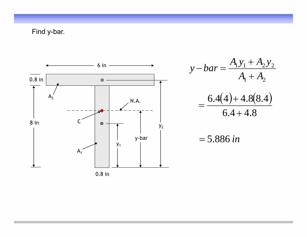
Find y-bar.
2211
AAyAyAbary
6 in
21 AA
4.88.444.6
0.8 in
A2N.A.
8.44.6
8 in y2C
in886.5A1
y1
y-bar
0.8 in
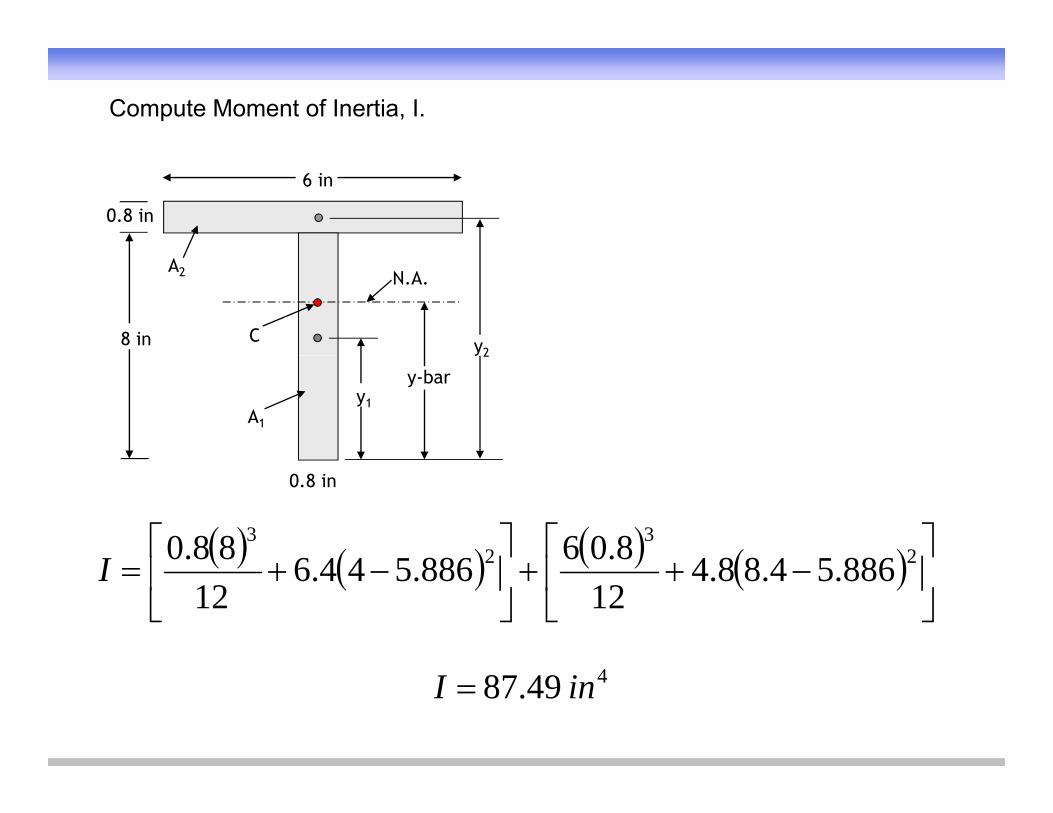
Compute Moment of Inertia, I.
6 in
0.8 in
8 in
A2
y2
N.A.
C
A1
y1
y2
y-bar
0.8 in
2
32
3
886548848.06886544688.0I
22 886.54.88.412
886.544.612
I
449.87 inI
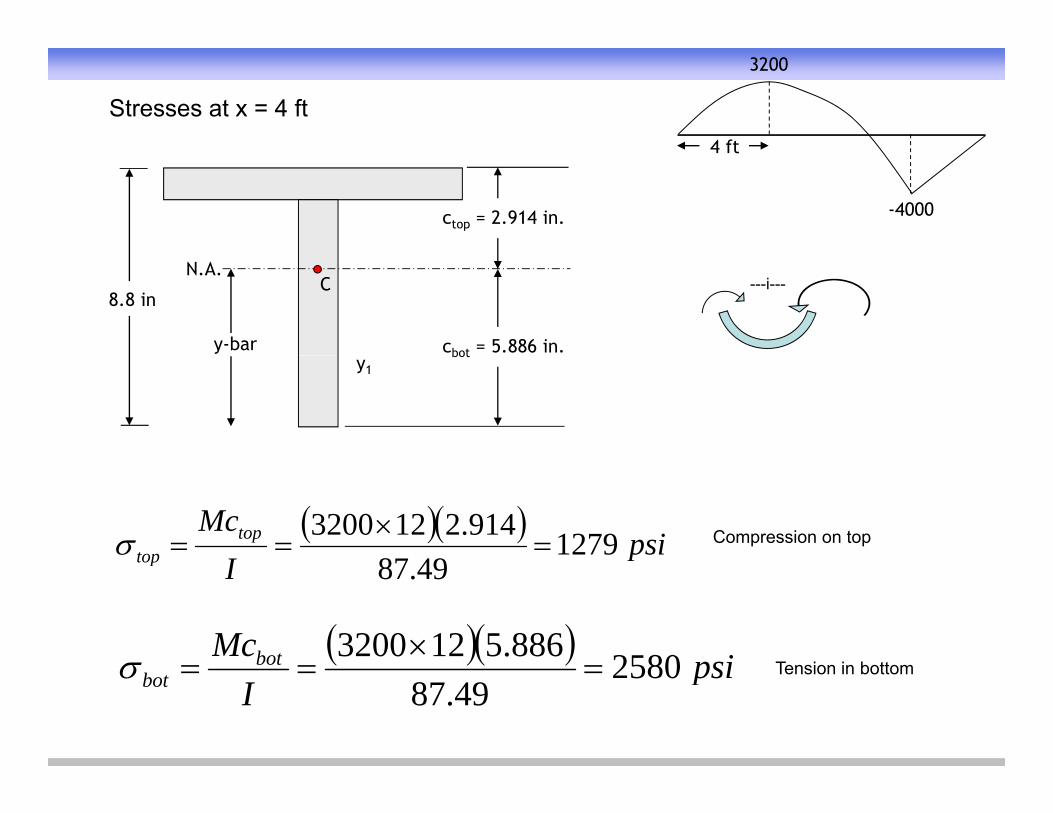
Stresses at x = 4 ft4 ft
3200
ctop = 2.914 in.
4 ft
-4000
8.8 in
y-bar
N.A.C
cbot = 5.886 in.
---i---
y1bot
psiI
Mctoptop 1279
4987914.2123200
Compression on top
psiMcbot 2580886.5123200
pItop 49.87
T i i b tt psi
Ibot
bot 258049.87
Tension in bottom
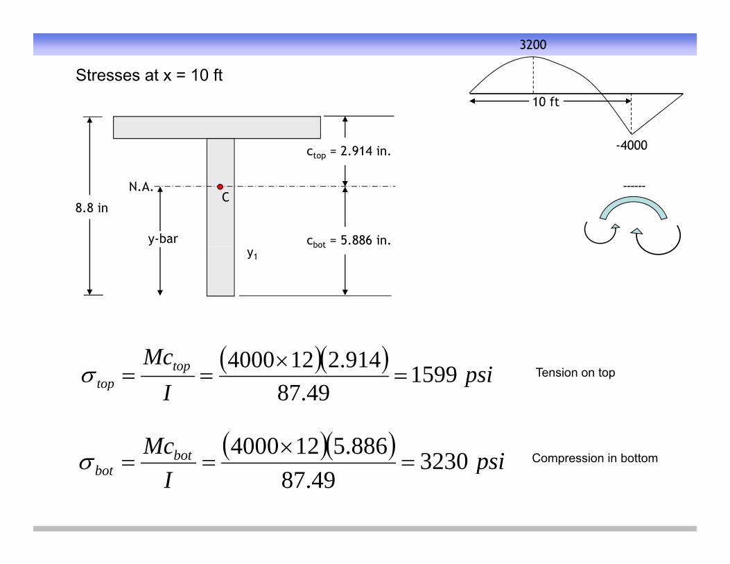
Stresses at x = 10 ft10 ft
3200
ctop = 2.914 in.
10 ft
-4000
8.8 in
y-bar
N.A.C
cbot = 5.886 in.
------
y1bot
psiI
Mctoptop 1599
4987914.2124000
Tension on top
psiMcbot 3230886.5124000
Ip 49.87
Compression in bottom psi
Ibot 323049.87
Compression in bottom
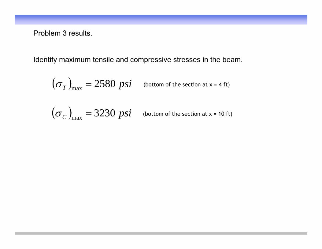
Problem 3 results.
Identify maximum tensile and compressive stresses in the beam.
psiT 2580max
(bottom of the section at x = 4 ft)
psiC 3230max (bottom of the section at x = 10 ft)
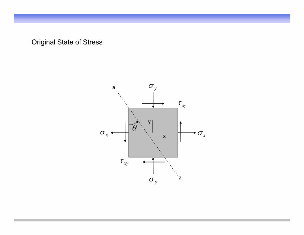
Original State of StressOriginal State of Stress
a y
y
xy
x x
x
a
xy
y
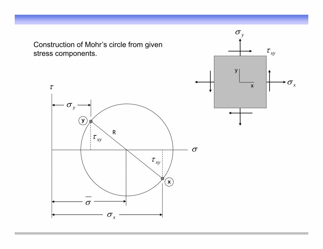
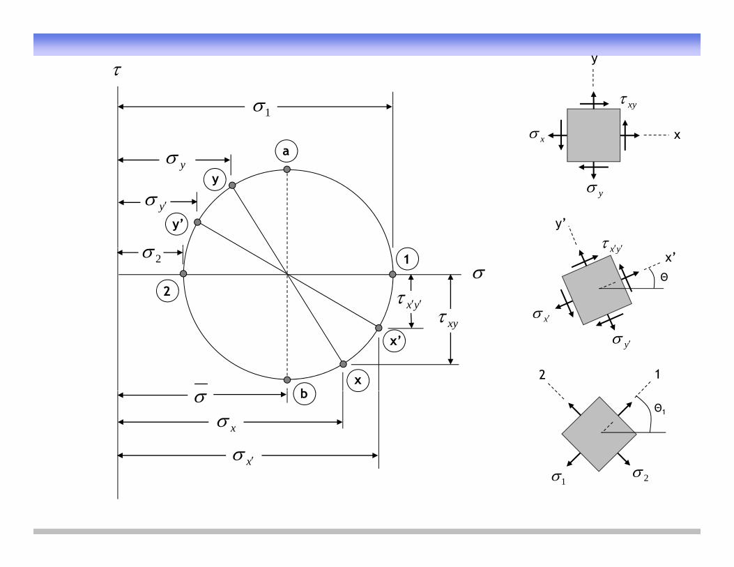
yConstruction of Mohr’s circle from given
y
xyConstruction of Mohr s circle from given stress components.
y
x x
y
R
y
xy
xy
xy
x
x
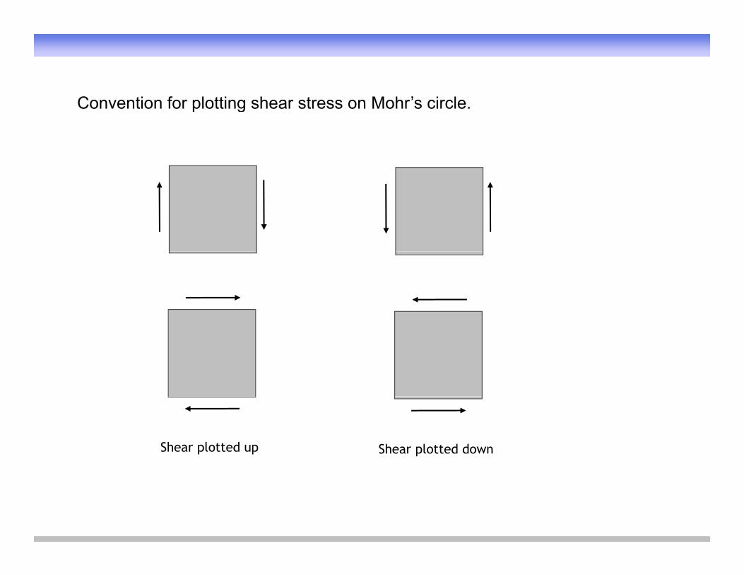
Convention for plotting shear stress on Mohr’s circleConvention for plotting shear stress on Mohr s circle.
Shear plotted up Shear plotted down
xy
y
y
xy
x x
1
y
a
y’
y
yx y’
yy
yx
Θ
yxx’
x2
12
y
x
2 1
xy
b
x’
x
x
Θ1
x
b
21
x
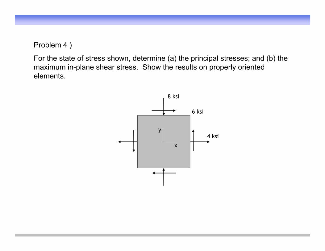
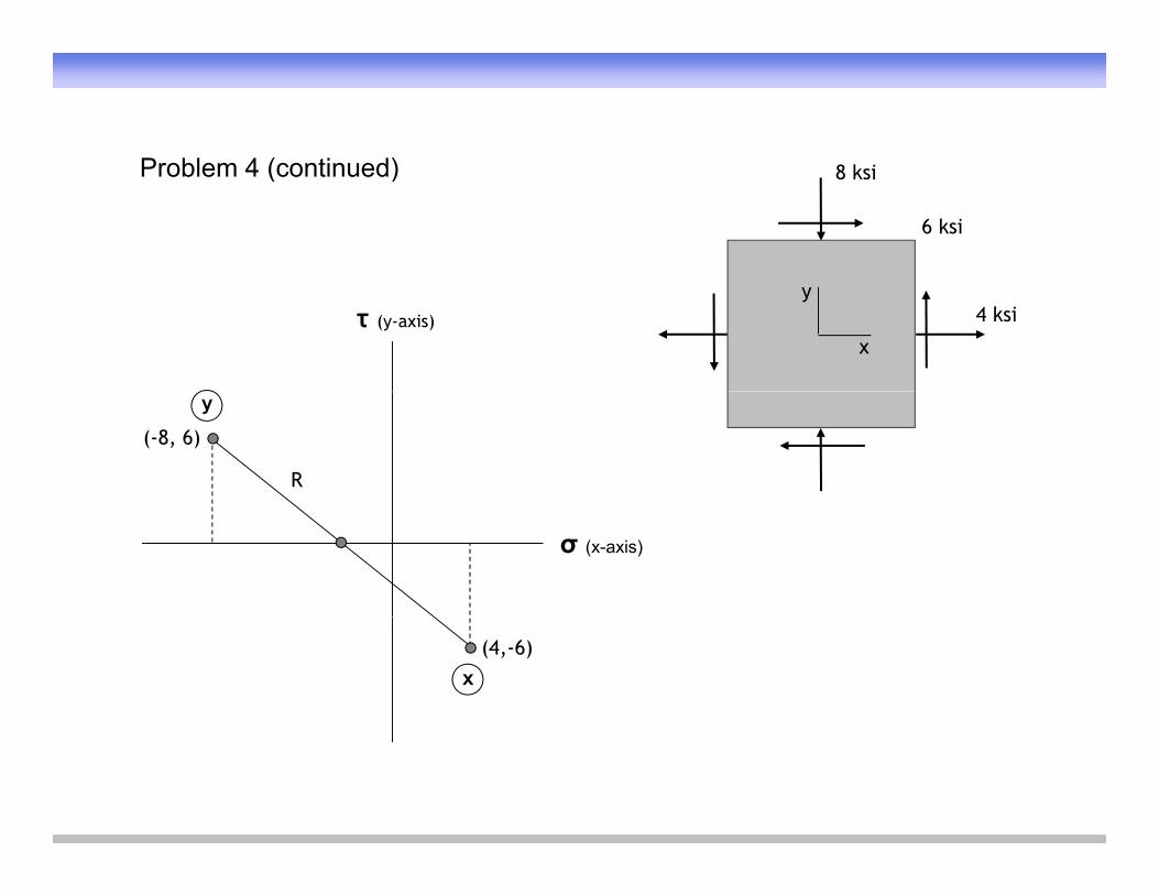
Problem 4 )Problem 4 )
For the state of stress shown, determine (a) the principal stresses; and (b) the maximum in-plane shear stress. Show the results on properly oriented elements.elements.
8 ksi
6 k i
4 ksi
6 ksi
y
x
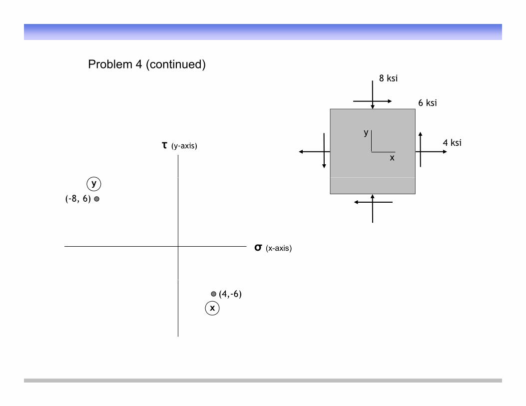
8 k iProblem 4 (continued)
8 ksi
6 ksi
τ (y-axis) 4 ksiy
x
(-8, 6)
y
σ (x-axis)
(4,-6)x
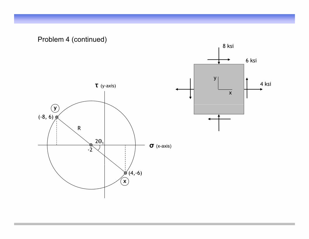
8 k iProblem 4 (continued) 8 ksi
6 ksi
Problem 4 (continued)
4 ksiy
xτ (y-axis)
R
(-8, 6)
y
σ (x-axis)
(4,-6)x

8 k iProblem 4 (continued) 8 ksi
6 ksi
Problem 4 (continued)
4 ksiy
xτ (y-axis)
R
(-8, 6)
y
σ (x-axis)-2
(4,-6)x
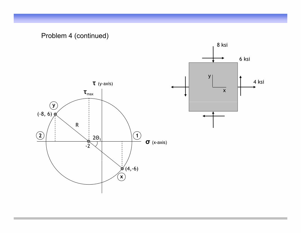
8 k iProblem 4 (continued)
8 ksi
6 ksi
4 ksiy
xτ (y-axis)
R
(-8, 6)
y
2Θ1
-2σ (x-axis)
(4,-6)x
8 k i
Problem 4 (continued)8 ksi
6 ksi
τmax
4 ksiy
xτ (y-axis)
y
R
(-8, 6)
12 2Θ1
-2σ (x-axis)
x(4,-6)
ττmax 10.49
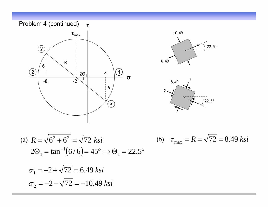
Problem 4 (continued)
y
R6
22.5°
6.49
σ12 42Θ1
6-8 -2
6
8.49 2
2
x 22.5°
2
(a) (b)ksiR 7266 22 ksiR 49.872max ( )
5.22456/6tan2 11
1
k i496722
max
ksi
ksi
49.10722
49.6722
2
1
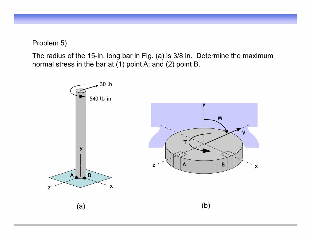
Problem 5)Problem 5)
The radius of the 15-in. long bar in Fig. (a) is 3/8 in. Determine the maximum normal stress in the bar at (1) point A; and (2) point B.
30 lb
540 lb-inyy
M
V
y
z xBA
T
z x
A B
z xBA
(a) (b)
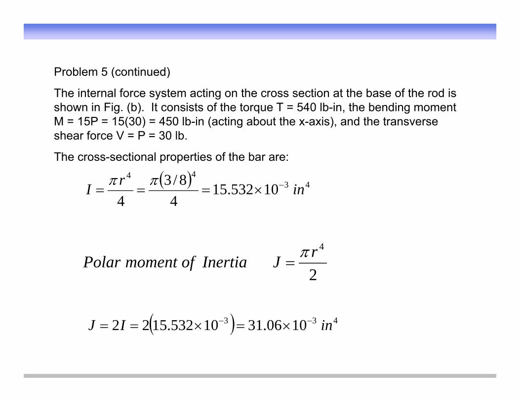
Problem 5 (continued)Problem 5 (continued)
The internal force system acting on the cross section at the base of the rod is shown in Fig. (b). It consists of the torque T = 540 lb-in, the bending moment M = 15P = 15(30) = 450 lb-in (acting about the x-axis), and the transverseM 15P 15(30) 450 lb in (acting about the x axis), and the transverse shear force V = P = 30 lb.
The cross-sectional properties of the bar are:
44 8/3 4344
10532.154
8/34
inrI
2
4rJInertiaofmomentPolar
433 100631105321522 inIJ
2
1006.3110532.1522 inIJ
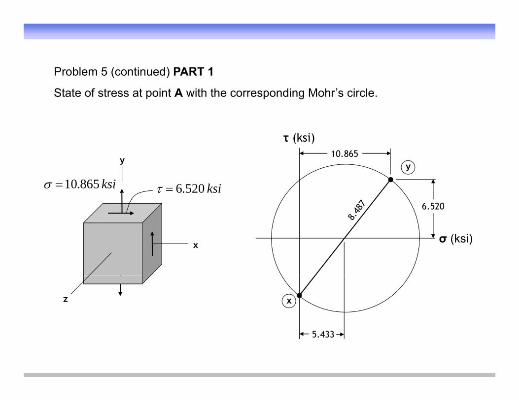
Problem 5 (continued) PART 1Problem 5 (continued) PART 1
State of stress at point A with the corresponding Mohr’s circle.
y
τ (ksi)
y10.865
ksi520.6ksi865.10
6.520
x σ (ksi)
z x
5.433
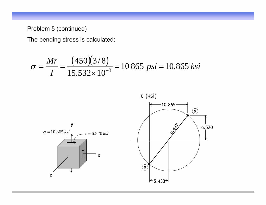
Problem 5 (continued)
Th b di t i l l t dThe bending stress is calculated:
k iiMr 86510865108/3450 ksipsiI
865.108651010532.15 3
τ (ksi)
y10.865
y
ksi520.6ksi865.106.520
x
x
z
x
5.433
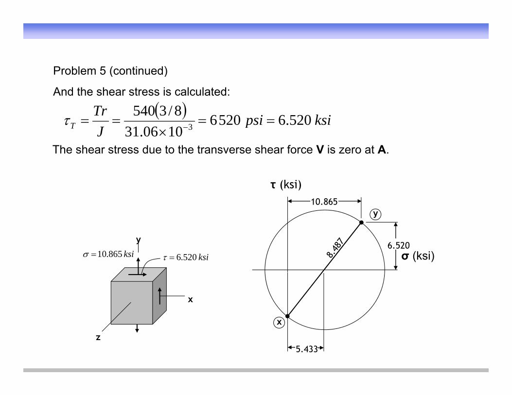
Problem 5 (continued)Problem 5 (continued)
And the shear stress is calculated:
ksipsiTrT 520652068/3540
ksipsiJT 520.65206
1006.31 3
The shear stress due to the transverse shear force V is zero at A.
τ (ksi)
y10.865
y
ksi520.6ksi865.10 σ (ksi)6.520
x
x
z
x
5.433
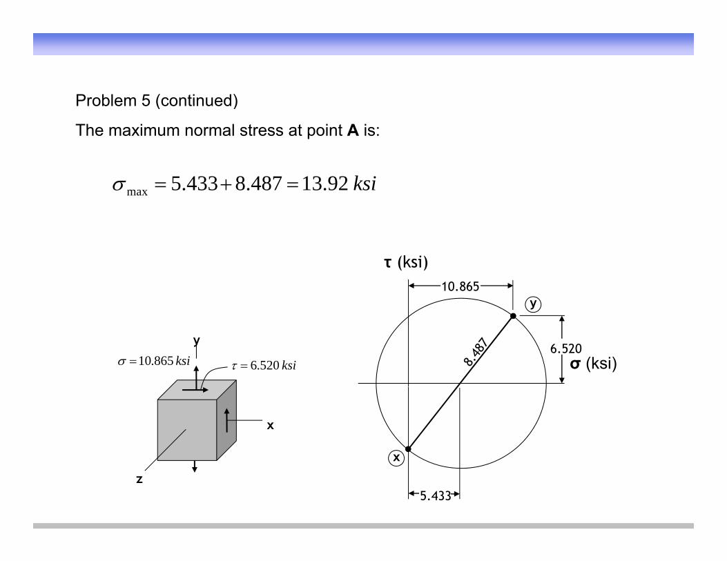
Problem 5 (continued)Problem 5 (continued)
The maximum normal stress at point A is:
ksi92.13487.8433.5max
τ (ksi)
y10.865
y
ksi520.6ksi865.10 σ (ksi)6.520
x
x
z
x
5.433
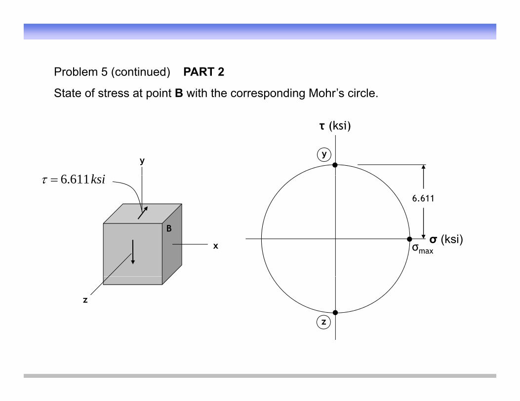
Problem 5 (continued) PART 2Problem 5 (continued) PART 2
State of stress at point B with the corresponding Mohr’s circle.
τ (ksi)
y
k i6116
τ (ksi)
y
ksi611.6
B
6.611
x
Bσ (ksi)
σmax
z
z
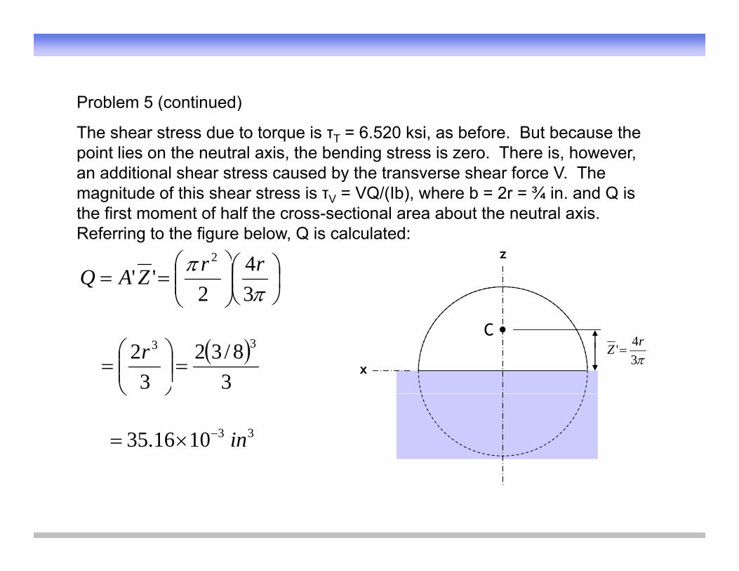
Problem 5 (continued)Problem 5 (continued)
The shear stress due to torque is τT = 6.520 ksi, as before. But because the point lies on the neutral axis, the bending stress is zero. There is, however, an additional shear stress caused by the transverse shear force V. Thean additional shear stress caused by the transverse shear force V. The magnitude of this shear stress is τV = VQ/(Ib), where b = 2r = ¾ in. and Q is the first moment of half the cross-sectional area about the neutral axis. Referring to the figure below, Q is calculated:
34
2''
2 rrZAQz
x
C
34' rZ
38/32
32 33
r
331016.35 in
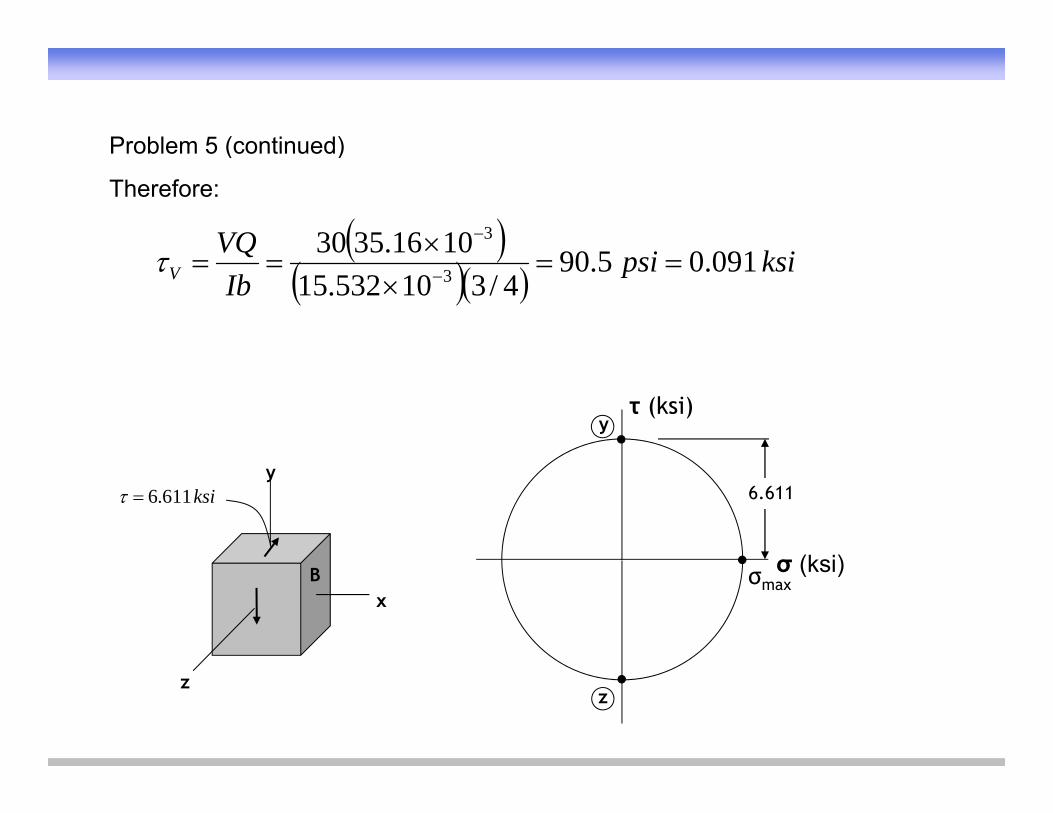
Problem 5 (continued)Problem 5 (continued)
Therefore:
k iiVQ 09105901016.3530 3 ksipsi
IbQ
V 091.05.904/310532.15 3
τ (ksi)y
yksi611.6
σ (ksi)
6.611
xB σ (ksi)σmax
zz
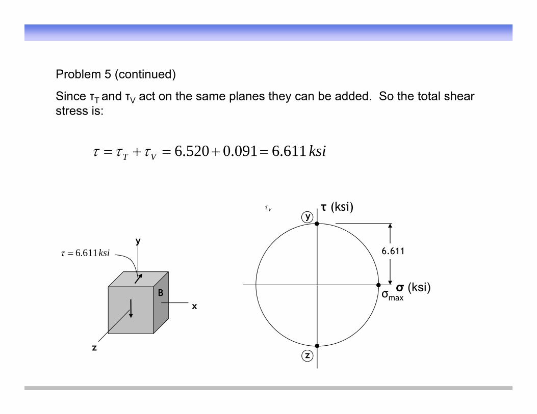
Problem 5 (continued)Problem 5 (continued)
Since τT and τV act on the same planes they can be added. So the total shear stress is:
ksiVT 611.6091.0520.6
τ (ksi)y
V
yksi611.6
σ (ksi)
6.611
xB σ (ksi)σmax
zz
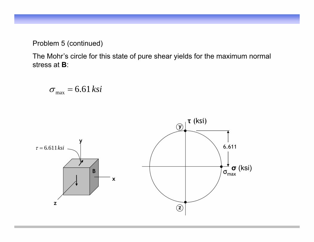
Problem 5 (continued)Problem 5 (continued)
The Mohr’s circle for this state of pure shear yields for the maximum normal stress at B:
ksi61.6max
τ (ksi)y
yksi611.6
σ (ksi)
6.611
xB σ (ksi)σmax
zz
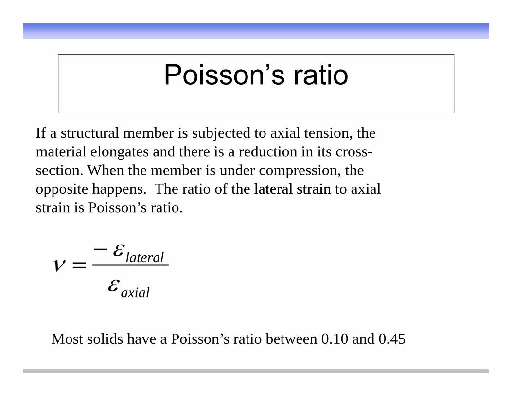
Poisson’s ratioPoisson s ratio
If a structural member is subjected to axial tension, the material elongates and there is a reduction in its cross-section When the member is under compression thesection. When the member is under compression, the opposite happens. The ratio of the laterallateral strainstrain to axial strain is Poisson’s ratio.
lateral
axial
Most solids have a Poisson’s ratio between 0.10 and 0.45
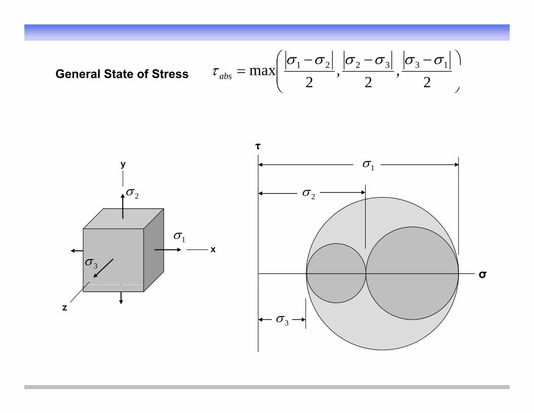
General State of Stress
,,max 133221 absGeneral State of Stress
2
,2
,2abs
y
τ
1
2 2
x1
3σ
z
3
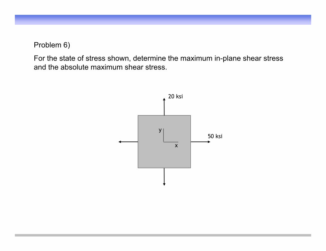
Problem 6)Problem 6)
For the state of stress shown, determine the maximum in-plane shear stress and the absolute maximum shear stress.
20 ksi
50 ksiy
x
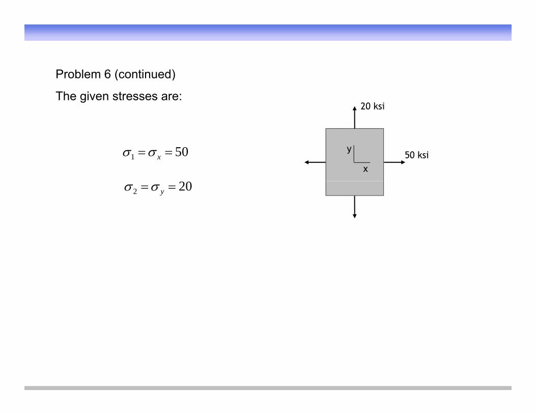
Problem 6 (continued)Problem 6 (continued)
The given stresses are:20 ksi
50 ksiy
x
501 x
202 y
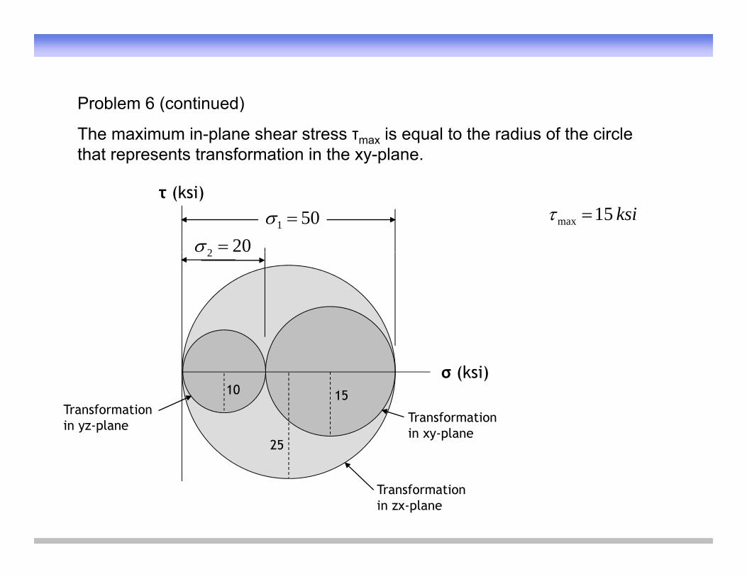
Problem 6 (continued)Problem 6 (continued)
The maximum in-plane shear stress τmax is equal to the radius of the circle that represents transformation in the xy-plane.
τ (ksi)
501 202
ksi15max
2
σ (ksi)10 15
25
15
Transformation in xy-plane
Transformation in yz-plane
Transformation in zx-plane
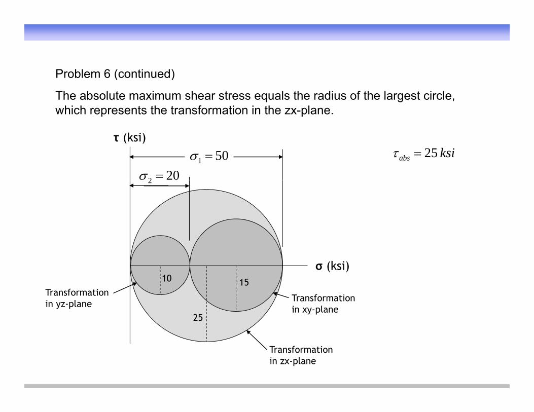
Problem 6 (continued)Problem 6 (continued)
The absolute maximum shear stress equals the radius of the largest circle, which represents the transformation in the zx-plane.
τ (ksi)
501 202
ksiabs 25
2
σ (ksi)10 15
25
15
Transformation in xy-plane
Transformation in yz-plane
Transformation in zx-plane
References:References:
Pytel and Kiusalaas, “Mechanics of Materials,”Thomson, 2003.
McCormac and Nelson, “Design of Reinforced Concrete,” Wiley, 2003.y
Thank You
andand
GOOD LUCK!!!