
S&T Expansion Evaporator PURE COOLER - vws-gmbh.euvws-gmbh.eu/downloads/pure-cooler.pdf ·...
12
0 S&T Expansion Evaporator PURE COOLER
Transcript of S&T Expansion Evaporator PURE COOLER - vws-gmbh.euvws-gmbh.eu/downloads/pure-cooler.pdf ·...
0
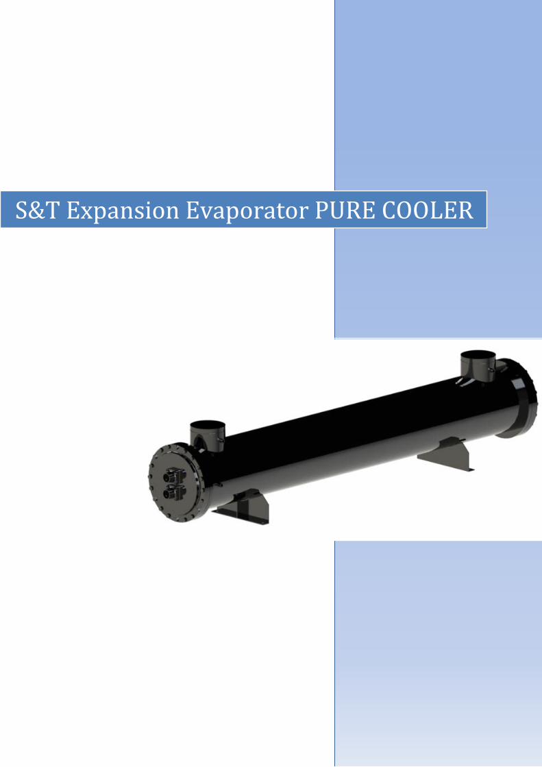
S&T Expansion Evaporator PURE COOLER

1
Technology With its revolutionary refrigerant distributor and singlepass, counter-current design, Alfa Laval’s new Pure Cooler shell and-tube evaporator series guaranties maximum efficiency, low costs and new levels of competitiveness. Meeting efficiency demands Ashrae 90.1 and building efficiency protocols, such as Greenbuilding and LEED, are demanding more an more high-efficient cooling systems and are setting the minimum efficiency ratings (EER > 5). These ratings can only be reached with the Pure Cooler product line solution, which makes the dry expansion technology close to the flooded evaporation one in terms of performance (Tev ≥ 4.5°C).
Unique design A number of new exclusive features contribute to Pure Cooler’s high level of performance. A unique patented refrigerant distribution system which has been optimized for R134a. A highly efficient single-pass and counter-current design, where refrigerant flows in one direction and the water in the other, allows for the best possible thermal exchange performance. Plastic baffles with a specific design to improve the water side performance and to avoid corrosion issues Exchange tubes Dext 7,94mm (5/16”) with a specific inner grooved pattern to maximize the R134a heat transfer coefficient and to limit the Pressure drop negative effects.
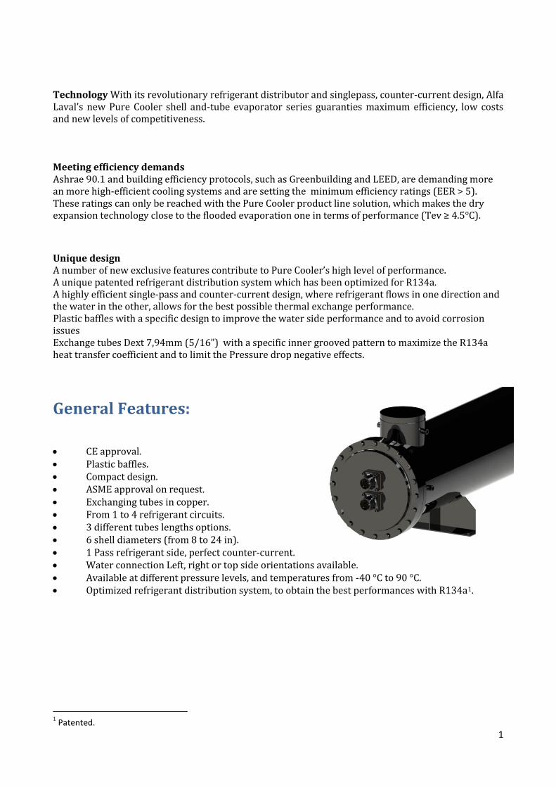
General Features:
• CE approval. • Plastic baffles. • Compact design. • ASME approval on request. • Exchanging tubes in copper. • From 1 to 4 refrigerant circuits. • 3 different tubes lengths options. • 6 shell diameters (from 8 to 24 in). • 1 Pass refrigerant side, perfect counter-current. • Water connection Left, right or top side orientations available. • Available at different pressure levels, and temperatures from -40 °C to 90 °C. • Optimized refrigerant distribution system, to obtain the best performances with R134a1.
1 Patented.

2
Design data
PED (CE) approval
Version Tubes Side Shell Side
PS (bar) TS (°C) Tmin (°C) PT (bar) PS (bar) TS (°C) Tmin (°C) PT (bar)
STD 16.5 50 -10 23.6 10 50 -10 14.3
BT 16.5 50 -40 23.6 10 50 -40 14.3
Available orientations The information related to water connection position is mandatory only if welded feet are required. Pay attention to the fact that nothing can be welded to the shell aftersales (support neither). This action void CE approval and could damage some internal components of the unit.
LEFT
TOP
RIGHT
3
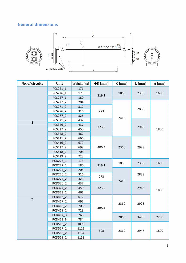
General dimensions
No. of circuits Unit Weight [kg] ΦD [mm] C [mm] L [mm] A [mm]
1
PCS221_1 171
219.1 1860 2338 1600 PCS226_1 173
PCS227_1 180 PCS227_2 204
2410
2888
1800
PCS271_2 312 273 PCS276_2 316
PCS277_2 326 PCS321_2 432
323.9 2918 PCS326_2 437 PCS327_2 450 PCS328_2 462 PCS411_2 666
406.4 2360 2928 PCS416_2 672 PCS417_2 692 PCS418_2 708 PCS419_2 723
2
PCD226_1 173 219.1
1860 2338 1600 PCD227_1 180 PCD227_2 204
2410
2888
1800
PCD276_2 316 273
PCD277_2 326 PCD326_2 437
323.9 2918 PCD327_2 450 PCD328_2 462 PCD416_2 672
406.4 2360 2928
PCD417_2 692 PCD418_2 708 PCD419_2 723 PCD417_3 766
2860 3498 2200 PCD418_3 784 PCD516_2 1093
508 2310 2947 1800 PCD517_2 1112 PCD518_2 1134 PCD519_2 1153
4
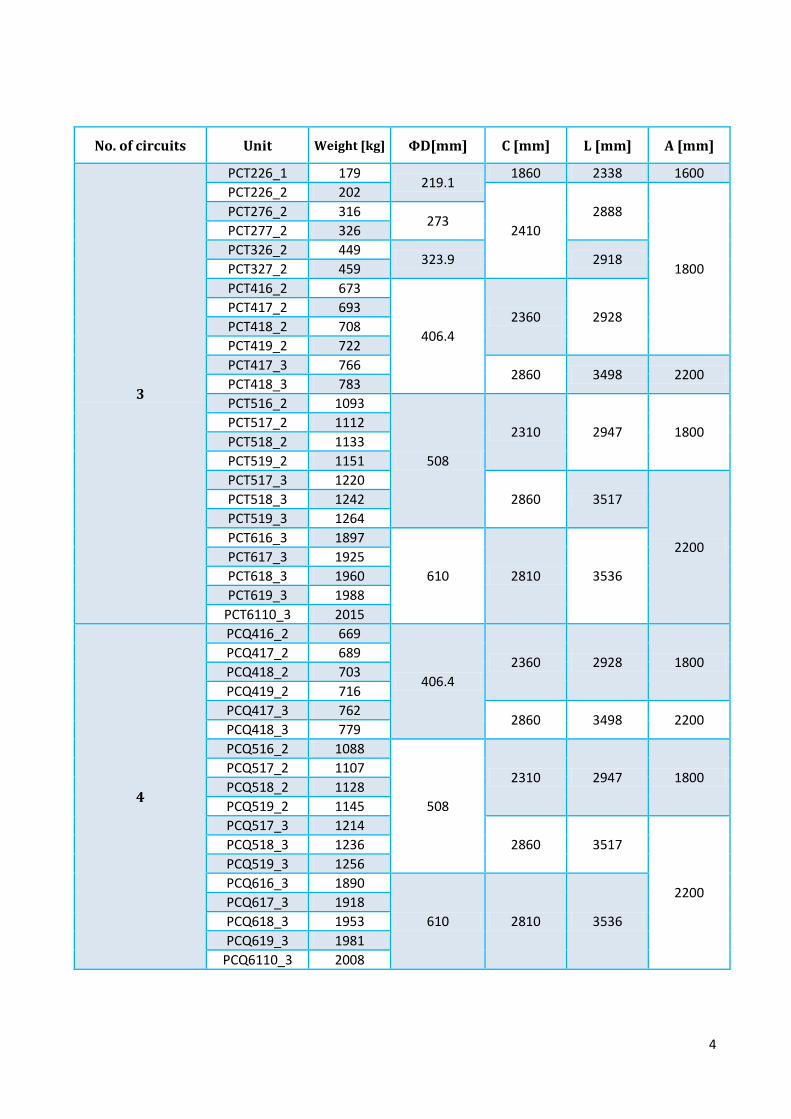
No. of circuits Unit Weight [kg] ΦD[mm] C [mm] L [mm] A [mm]
3
PCT226_1 179 219.1
1860 2338 1600 PCT226_2 202
2410 2888
1800
PCT276_2 316 273
PCT277_2 326 PCT326_2 449
323.9 2918 PCT327_2 459 PCT416_2 673
406.4 2360 2928
PCT417_2 693 PCT418_2 708 PCT419_2 722 PCT417_3 766
2860 3498 2200 PCT418_3 783 PCT516_2 1093
508
2310 2947 1800 PCT517_2 1112 PCT518_2 1133 PCT519_2 1151 PCT517_3 1220
2860 3517
2200
PCT518_3 1242 PCT519_3 1264 PCT616_3 1897
610 2810 3536 PCT617_3 1925 PCT618_3 1960 PCT619_3 1988
PCT6110_3 2015
4
PCQ416_2 669
406.4 2360 2928 1800
PCQ417_2 689 PCQ418_2 703 PCQ419_2 716 PCQ417_3 762
2860 3498 2200 PCQ418_3 779 PCQ516_2 1088
508
2310 2947 1800 PCQ517_2 1107 PCQ518_2 1128 PCQ519_2 1145 PCQ517_3 1214
2860 3517
2200
PCQ518_3 1236 PCQ519_3 1256 PCQ616_3 1890
610 2810 3536 PCQ617_3 1918 PCQ618_3 1953 PCQ619_3 1981
PCQ6110_3 2008
5
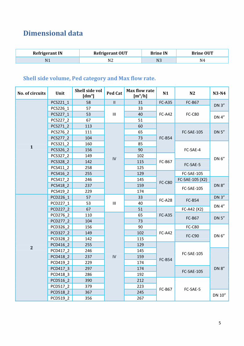
Dimensional data
Refrigerant IN Refrigerant OUT Brine IN Brine OUT N1 N2 N3 N4
Shell side volume, Ped category and Max flow rate.
No. of circuits Unit Shell side vol [dmᶟ] Ped Cat Max flow rate
[mᶟ/h] N1 N2 N3-N4
1
PCS221_1 58 II 31 FC-A35 FC-B67 DN 3”
PCS226_1 57 III
33 FC-A42 FC-C80 PCS227_1 53 40
DN 4” PCS227_2 67 51 PCS271_2 113
IV
60
FC-B54 FC-SAE-105 DN 5” PCS276_2 111 65
PCS277_2 104 73 PCS321_2 160 85
FC-SAE-4
DN 6”
PCS326_2 156 90 PCS327_2 149 102
FC-B67 PCS328_2 142 115 FC-SAE-5
PCS411_2 258 125 PCS416_2 255 129
FC-C80
FC-SAE-105 PCS417_2 246 145 FC-SAE-105 (X2)
DN 8” PCS418_2 237 159 FC-SAE-105
PCS419_2 229 174
2
PCD226_1 57 III
33 FC-A28 FC-B54
DN 3” PCD227_1 53 40
DN 4” PCD227_2 67 51
FC-A35 FC-A42 (X2)
PCD276_2 110
IV
65 FC-B67 DN 5”
PCD277_2 104 73 PCD326_2 156 90
FC-A42 FC-C80
DN 6” PCD327_2 149 102
FC-C90 PCD328_2 142 115 PCD416_2 255 129
FC-B54 FC-SAE-105
PCD417_2 246 145
DN 8”
PCD418_2 237 159 PCD419_2 229 174 PCD417_3 297 174
FC-SAE-105 PCD418_3 286 192 PCD516_2 390 212
FC-B67 FC-SAE-5 PCD517_2 379 223 PCD518_2 367 245
DN 10” PCD519_2 356 267
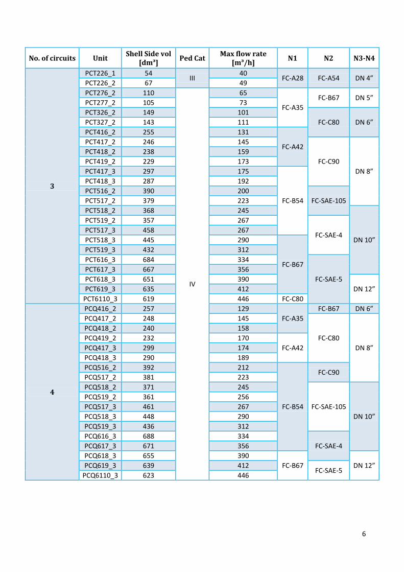
6
No. of circuits Unit Shell Side vol [dmᶟ] Ped Cat Max flow rate
[mᶟ/h] N1 N2 N3-N4
3
PCT226_1 54 III
40 FC-A28 FC-A54 DN 4”
PCT226_2 67 49 PCT276_2 110
IV
65
FC-A35 FC-B67 DN 5”
PCT277_2 105 73 PCT326_2 149 101
FC-C80 DN 6” PCT327_2 143 111 PCT416_2 255 131
FC-A42 PCT417_2 246 145
FC-C90 DN 8”
PCT418_2 238 159 PCT419_2 229 173 PCT417_3 297 175
FC-B54
PCT418_3 287 192 PCT516_2 390 200
FC-SAE-105 PCT517_2 379 223 PCT518_2 368 245
DN 10”
PCT519_2 357 267
FC-SAE-4 PCT517_3 458 267 PCT518_3 445 290
FC-B67
PCT519_3 432 312 PCT616_3 684 334
FC-SAE-5 PCT617_3 667 356 PCT618_3 651 390
DN 12” PCT619_3 635 412 PCT6110_3 619 446 FC-C80
4
PCQ416_2 257 129 FC-A35
FC-B67 DN 6” PCQ417_2 248 145
FC-C80 DN 8”
PCQ418_2 240 158 PCQ419_2 232 170
FC-A42 PCQ417_3 299 174 PCQ418_3 290 189 PCQ516_2 392 212
FC-B54
FC-C90 PCQ517_2 381 223 PCQ518_2 371 245
FC-SAE-105 DN 10”
PCQ519_2 361 256 PCQ517_3 461 267 PCQ518_3 448 290 PCQ519_3 436 312 PCQ616_3 688 334
FC-SAE-4 PCQ617_3 671 356 PCQ618_3 655 390
FC-B67 DN 12” PCQ619_3 639 412 FC-SAE-5
PCQ6110_3 623 446
7
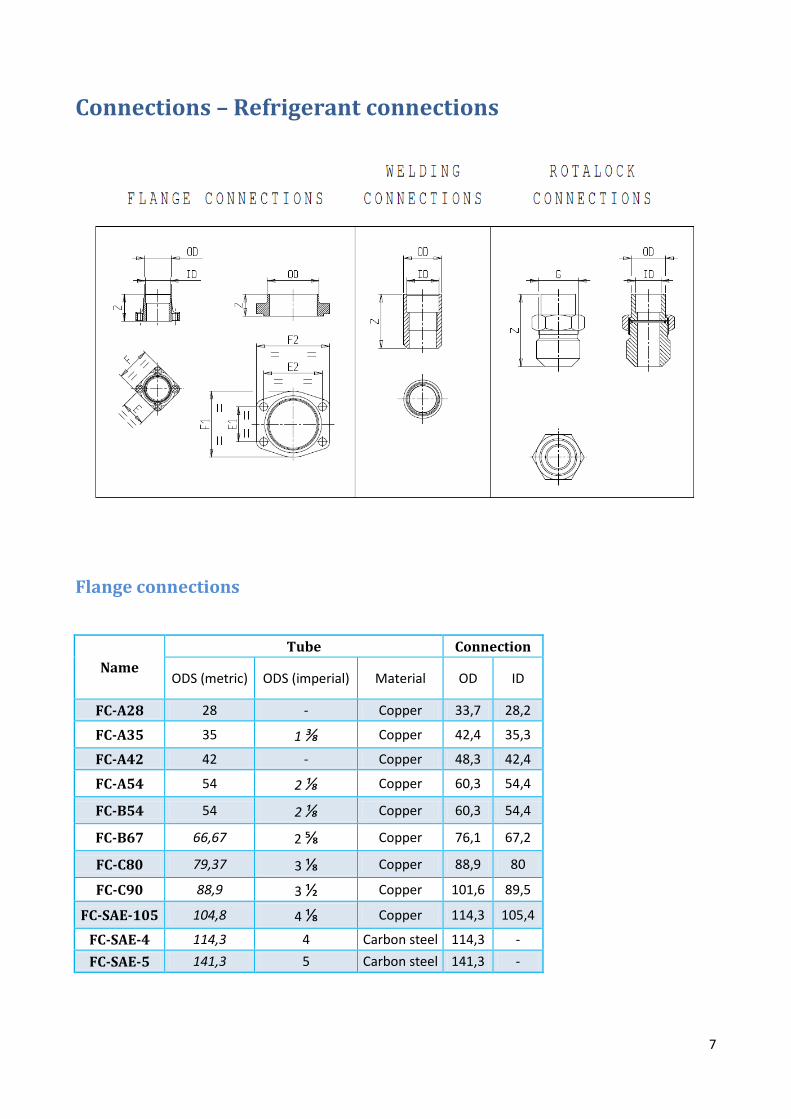
Connections – Refrigerant connections
Flange connections
Name Tube Connection
ODS (metric) ODS (imperial) Material OD ID
FC-A28 28 - Copper 33,7 28,2
FC-A35 35 1 ⅜ Copper 42,4 35,3
FC-A42 42 - Copper 48,3 42,4
FC-A54 54 2 ⅛ Copper 60,3 54,4
FC-B54 54 2 ⅛ Copper 60,3 54,4
FC-B67 66,67 2 ⅝ Copper 76,1 67,2
FC-C80 79,37 3 ⅛ Copper 88,9 80
FC-C90 88,9 3 ½ Copper 101,6 89,5
FC-SAE-105 104,8 4 ⅛ Copper 114,3 105,4
FC-SAE-4 114,3 4 Carbon steel 114,3 - FC-SAE-5 141,3 5 Carbon steel 141,3 -
8
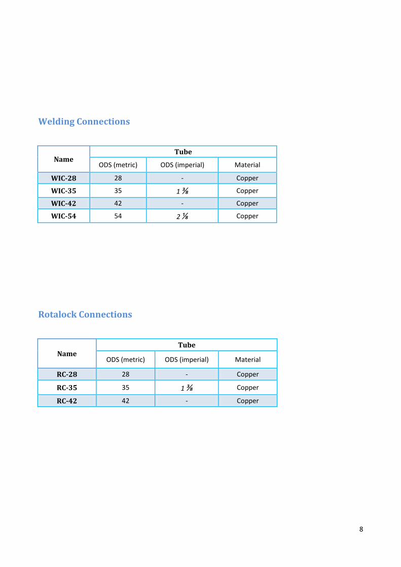
Welding Connections
Name Tube
ODS (metric) ODS (imperial) Material
WIC-28 28 - Copper
WIC-35 35 1 ⅜ Copper
WIC-42 42 - Copper
WIC-54 54 2 ⅛ Copper
Rotalock Connections
Name Tube
ODS (metric) ODS (imperial) Material
RC-28 28 - Copper
RC-35 35 1 ⅜ Copper
RC-42 42 - Copper

9
Connections – Brine connections
Nozzles (designed for flexible joint)
Nozzle ΦV Suggested coupling DN 3” 88,9
Victaulic Flexible Coupling, Style 75 DN 4” 114,3 DN 5” 141,3 DN 6” 168,3 DN 8” 218,3
DN 10” 272 Victaulic Standard Flexible Coupling, Style 77
DN 12” 322,8
10
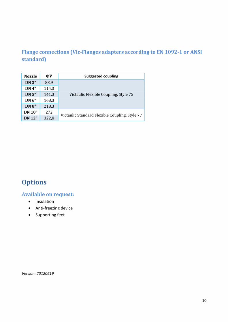
Flange connections (Vic-Flanges adapters according to EN 1092-1 or ANSI standard)
Nozzle ΦV Suggested coupling DN 3” 88,9
Victaulic Flexible Coupling, Style 75 DN 4” 114,3 DN 5” 141,3 DN 6” 168,3 DN 8” 218,3
DN 10” 272 Victaulic Standard Flexible Coupling, Style 77
DN 12” 322,8
Options
Available on request: • Insulation • Anti-freezing device • Supporting feet
Version: 20120619