Sinusoids Phasors Phasor Relationships for Circuit...
106
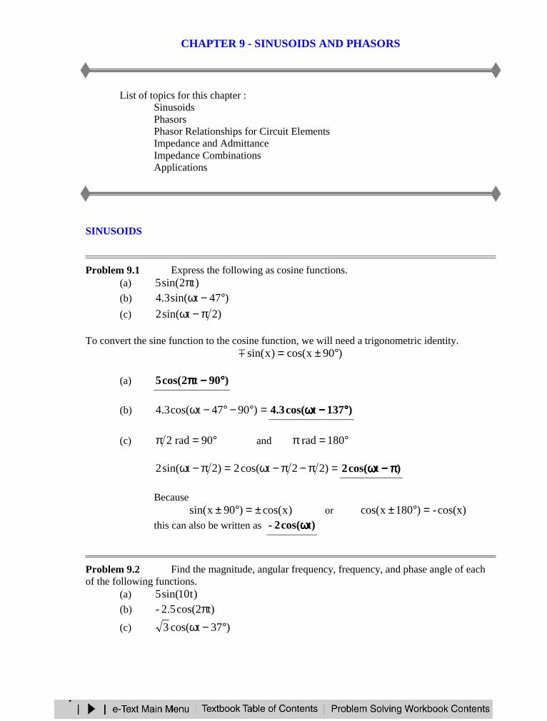
CHAPTER 9 - SINUSOIDS AND PHASORS List of topics for this chapter : Sinusoids Phasors Phasor Relationships for Circuit Elements Impedance and Admittance Impedance Combinations Applications SINUSOIDS Problem 9.1 Express the following as cosine functions. (a) ) t 2 sin( 5 π (b) ) 47 t sin( 3 . 4 ° − ω (c) ) 2 t sin( 2 π − ω To convert the sine function to the cosine function, we will need a trigonometric identity. ) 90 x cos( ) x sin( ° ± = (a) ) 90 t 2 cos( 5 ° − π (b) = ° − ° − ω ) 90 47 t cos( 3 . 4 ) 137 t cos( 3 . 4 ° − ω (c) ° = π 90 rad 2 and ° = π 180 rad = π − π − ω = π − ω ) 2 2 t cos( 2 ) 2 t sin( 2 ) t cos( 2 π − ω Because ) x cos( ) 90 x sin( ± = ° ± or cos(x) - ) 180 x cos( = ° ± this can also be written as t) cos( 2 - ω Problem 9.2 Find the magnitude, angular frequency, frequency, and phase angle of each of the following functions. (a) ) t 10 sin( 5 (b) t) cos(2 2.5 - π (c) ) 37 t cos( 3 ° − ω
Transcript of Sinusoids Phasors Phasor Relationships for Circuit...
CHAPTER 9 - SINUSOIDS AND PHASORS
List of topics for this chapter :SinusoidsPhasorsPhasor Relationships for Circuit ElementsImpedance and AdmittanceImpedance CombinationsApplications
SINUSOIDS
Problem 9.1 Express the following as cosine functions.(a) )t2sin(5 π(b) )47tsin(3.4 °−ω(c) )2tsin(2 π−ω
To convert the sine function to the cosine function, we will need a trigonometric identity.)90xcos()xsin( °±=
(a) )90t2cos(5 °°°°−−−−ππππ
(b) =°−°−ω )9047tcos(3.4 )137tcos(3.4 °°°°−−−−ωωωω
(c) °=π 90rad2 and °=π 180rad
=π−π−ω=π−ω )22tcos(2)2tsin(2 )tcos(2 ππππ−−−−ωωωω
Because)xcos()90xsin( ±=°± or cos(x)-)180xcos( =°±
this can also be written as t)cos(2- ωωωω
Problem 9.2 Find the magnitude, angular frequency, frequency, and phase angle of eachof the following functions.
(a) )t10sin(5(b) t)cos(22.5- π(c) )37tcos(3 °−ω
(a) Consider )tsin(V)t(v m φ+ω= . Also, note that f2π=ω .
=mV 5 =ω 10 =f ππππ210 , =φ °°°°0
(b) Consider )tcos(V)t(v m φ+ω=
=mV 5.2 =ω ππππ2 =f 1 , =φ °°°°180
Note that °=φ 180 due to the negative sign in front of the function.
(c) Consider )tcos(V)t(v m φ+ω=
=mV 3 =ω ωωωω =f ππππωωωω 2 , =φ °°°°37-
Problem 9.3 [9.5] Given )60tsin(20v1 °+ω= and )10tcos(60v2 °−ω= ,determine the phase angle between the two sinusoids and which one lags the other.
)30tcos(20)9060tcos(20)60tsin(20v1 °−ω=°−°+ω=°+ω=)10tcos(60v2 °−ω=
This indicates that the phase angle between the two signals is °°°°20 and that 21 vlagsv .
PHASORS
Problem 9.4 Convert the following into phasors.(a) )tsin(100 ω(b) )tcos(20 ω(c) )80tcos(50 °−ω(d) )45tsin(25 °+ω
(a) °°°°∠∠∠ ∠ 0100 assuming a reference of )tsin(A φ+ω
(b) °°°°∠∠∠ ∠ 020 assuming a reference of )tcos(A φ+ω
(c) °°°°∠∠∠ ∠ 80-50 assuming a reference of )tcos(A φ+ω
(d) °°°°∠∠∠ ∠ 4525 assuming a reference of )tsin(A φ+ω
Problem 9.5 [9.11] Let °∠= 408X and °∠= 30-10Y . Evaluate the followingquantities and express your results in polar form.
(a) ∗+ XYX )(
(b) ∗− )( YX(c) XYX /)( +
(a) °∠+°∠=+ 30-10408YX)5j66.8()142.5j128.6( −++=+ YX°∠=+=+ 55.079.14142.0j79.14YX
)40-8)(0.5579.14()( °∠°∠=+ ∗XYX
=+ ∗XYX )( °°°°∠∠∠∠ 39.45-3.118
(b) °∠−°∠=− 30-10408YX)5j66.8()142.5j128.6( −−+=− YX
°∠=+=− 10445.10142.10j532.2-YX
=− ∗)( YX °°°°∠∠∠∠ 104-45.10
(c) From (a), °∠=+ 55.079.14YX
=°∠
°∠=
+408
55.079.14
XYX
=+ XYX /)( °°°°∠∠∠∠ 39.45-849.1
Problem 9.6 If )tsin(A φ+ω is used as a common reference, what would be the phasors?
(a) )tsin(100 ω(b) )tcos(20 ω(c) )80tcos(50 °−ω(d) )45tsin(25 °+ω
(a) °°°°∠∠∠∠ 0100
(b) °°°°∠∠∠∠ 9020
(c) °°°°∠∠∠∠ 1050
(d) °°°°∠∠∠∠ 4525
PHASOR RELATIONSHIPS FOR CIRCUIT ELEMENTS
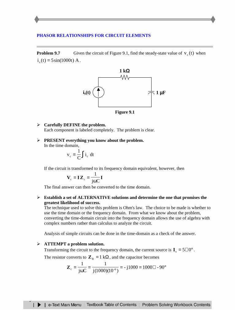
Problem 9.7 Given the circuit of Figure 9.1, find the steady-state value of )t(vc when
A)t1000sin(5)t(is = .
Figure 9.1
Carefully DEFINE the problem.Each component is labeled completely. The problem is clear.
PRESENT everything you know about the problem.In the time domain,
∫= dtiC
1v cc
If the circuit is transformed to its frequency domain equivalent, however, then
IZIVCj
1cc ω
==
The final answer can then be converted to the time domain.
Establish a set of ALTERNATIVE solutions and determine the one that promises thegreatest likelihood of success.The technique used to solve this problem is Ohm's law. The choice to be made is whether touse the time domain or the frequency domain. From what we know about the problem,converting the time-domain circuit into the frequency domain allows the use of algebra withcomplex numbers rather than calculus to analyze the circuit.
Analysis of simple circuits can be done in the time-domain as a check of the answer.
ATTEMPT a problem solution.Transforming the circuit to the frequency domain, the current source is °∠= 05sI .
The resistor converts to Ω= k1RZ , and the capacitor becomes
°∠===ω
= 90-1000j1000-)10)(1000(j
1
Cj
16-cZ
1 µµµµF
1 kΩΩΩΩ
+
vs(t)
−−−−
+
vc(t)
−−−−
is(t)
Thus,°∠=°∠°∠= 90-5000)90-1000)(05(cV
or V)90t1000sin(5000)t(vc °−=
EVALUATE the solution and check for accuracy.Using KVL in the frequency domain,
V05000)1000)(05(RR °∠=°∠== ZIV
°∠== 90-5000cc ZIV
°∠+°∠=+= 90-500005000cRs VVV
°∠=−= 45-250005000j5000sV
or V)45t1000sin(25000)t(vs °−=
Using KVL in the time domain,
∫ ∫== dt)t1000sin(510
1dt)t(i
C
1)t(v 6-cc
]cos(1000t)-)[5(1010
1)t(v 36-c =
V)90t1000sin(5000)t(vc °−=
V)t1000sin(5000)t(iR)t(vR ==
)t(v)t(v)t(v cRs +=)90t1000sin(5000)t1000sin(5000)t(vs °−+=
V)45t1000sin(25000)t(vs °−=
Our check for accuracy was successful.
Has the problem been solved SATISFACTORILY? If so, present the solution; if not,then return to “ALTERNATIVE solutions” and continue through the process again.This problem has been solved satisfactorily.
=)t(vc V)90t1000sin(5000 °°°°−−−−
Problem 9.8 Given 100=ω , determine the frequency domain ( ω= js ) values for thefollowing elements.
(a) ΩΩΩΩΩ= M100,M1,k1,10,1R(b) H40,mH5,H1,H5,H10L µ=(c) pF10,F5,F333,mF2C µµ=
(a) =R ΩΩΩΩΩΩΩΩΩΩΩΩΩΩΩΩΩΩΩΩ M100,M1,k1,10,1
(b) =ωL ΩΩΩΩΩΩΩΩΩΩΩΩΩΩΩΩΩΩΩΩ m4,m500,100,500,1000
where the units are ohms of inductive reactance
(c) =ωC
1ΩΩΩΩΩΩΩΩΩΩΩΩΩΩΩΩ G1,k2,30,5
where the units are ohms of capacitive reactance
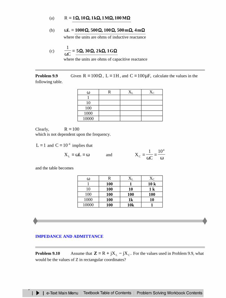
Problem 9.9 Given Ω= 100R , H1L = , and ,F100C µ= calculate the values in thefollowing table.
ω R XL XC
1101001000
10000
Clearly, 100R =which is not dependent upon the frequency.
1L = and -410C = implies that
ω=ω= LXL andω
=ω
=4
C
10
C
1X
and the table becomes
ω R XL XC
1 100 1 10 k10 100 10 1 k100 100 100 100
1000 100 1k 1010000 100 10k 1
IMPEDANCE AND ADMITTANCE
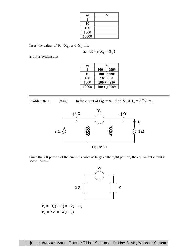
Problem 9.10 Assume that .jXjXR CL −+=Z For the values used in Problem 9.9, what
would be the values of Z in rectangular coordinates?
ω Z110
100100010000
Insert the values of R , LX , and CX into
)XX(jR CL −+=Zand it is evident that
ω Z1 100 – j 999910 100 – j 990
100 100 + j 01000 100 + j 99010000 100 + j 9999
Problem 9.11 [9.43] In the circuit of Figure 9.1, find sV if A02o °∠=I .
Figure 9.1
Since the left portion of the circuit is twice as large as the right portion, the equivalent circuit isshown below.
)j1(2)j1(o1 −−=−−= IV
)j1(42 12 −−== VV
Vs
2 ΩΩΩΩ 1 ΩΩΩΩ
–j ΩΩΩΩ
j4 ΩΩΩΩ
Io+ −
–j2 ΩΩΩΩ
j2 ΩΩΩΩ
Z2 Z
+ −
+
V2
−−−−
−−−−
V1
+
Vs
)j1(621s −=+= VVV
=sV V513485.8 °°°°∠∠∠ ∠
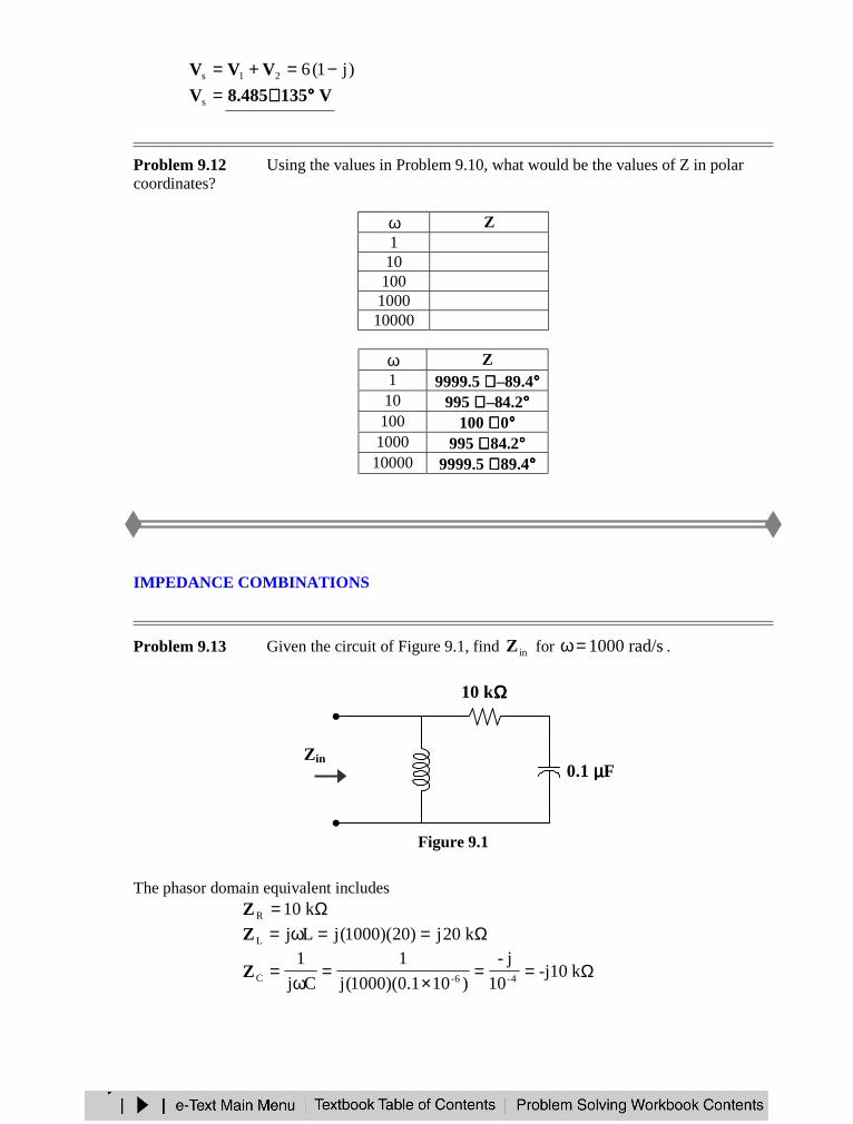
Problem 9.12 Using the values in Problem 9.10, what would be the values of Z in polarcoordinates?
ω Z1
101001000
10000
ω Z1 9999.5 ∠∠∠ ∠ –89.4°°°°10 995 ∠∠∠ ∠ –84.2°°°°
100 100 ∠∠∠ ∠ 0°°°°1000 995 ∠∠∠ ∠ 84.2°°°°
10000 9999.5 ∠∠∠ ∠ 89.4°°°°
IMPEDANCE COMBINATIONS
Problem 9.13 Given the circuit of Figure 9.1, find inZ for rad/s1000=ω .
Figure 9.1
The phasor domain equivalent includesΩ= k10RZ
Ω==ω= k20j)20)(1000(jLjLZ
Ω==×
=ω
= k-j1010
j-
)101.0)(1000(j
1
Cj
14-6-CZ
20 H 0.1 µµµµF
10 kΩΩΩΩ
Zin
)k10jk10(||k20j)(|| CRLin −=+= ZZZZ
)j1)(10(
)j1)(k200(
10j10
)10j10(k20j
k10jk10k20j
)k10jk10)(k20j(in +
+=
+−
=−+−
=Z
=inZ ΩΩΩΩk20
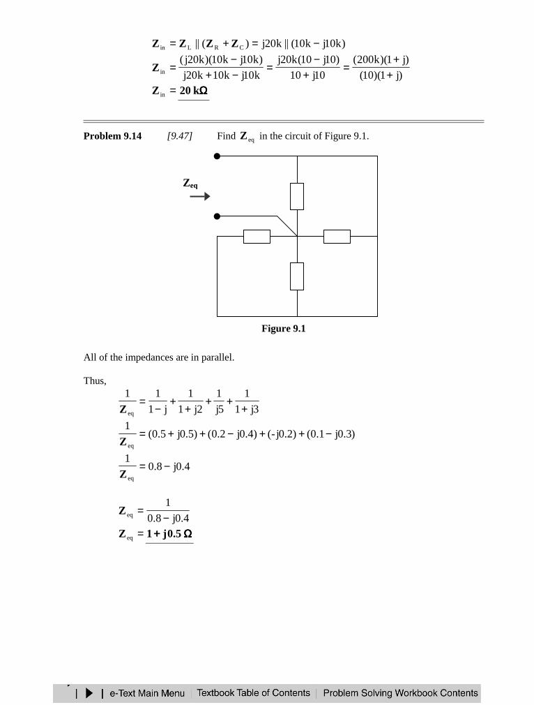
Problem 9.14 [9.47] Find eqZ in the circuit of Figure 9.1.
Figure 9.1
All of the impedances are in parallel.
Thus,
3j1
1
5j
1
2j1
1
j1
11
eq +++
++
−=
Z
)3.0j1.0()2.0j-()4.0j2.0()5.0j5.0(1
eq
−++−++=Z
4.0j8.01
eq
−=Z
4.0j8.0
1eq −
=Z
=eqZ ΩΩΩΩ++++ 5.0j1
1 – j ΩΩΩΩZeq
1 + j3 ΩΩΩΩ 1 + j2 ΩΩΩΩ
j5 ΩΩΩΩ
APPLICATIONS
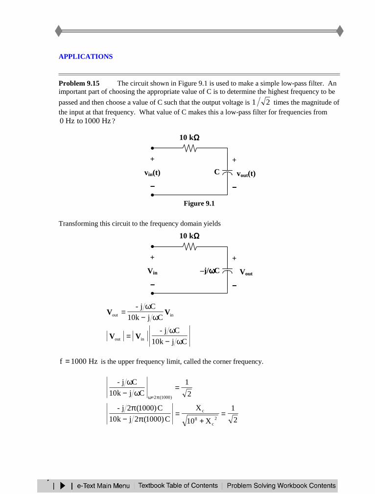
Problem 9.15 The circuit shown in Figure 9.1 is used to make a simple low-pass filter. Animportant part of choosing the appropriate value of C is to determine the highest frequency to be
passed and then choose a value of C such that the output voltage is 21 times the magnitude ofthe input at that frequency. What value of C makes this a low-pass filter for frequencies from
Hz1000toHz0 ?
Figure 9.1
Transforming this circuit to the frequency domain yields
inout Cjk10
Cj-VV
ω−ω
=
Cjk10
Cj-inout ω−
ω= VV
Hz1000f = is the upper frequency limit, called the corner frequency.
2
1
Cjk10
Cj-
)1000(2
=ω−
ω
π=ω
2
1
X10
X
C)1000(2jk10
C)1000(2j-2
c8
c =+
=π−
π
10 kΩΩΩΩ
C
+
vout(t)
−−−−
+
vin(t)
−−−−
10 kΩΩΩΩ
–j/ωωωωC
+
Vout
−−−−
+
Vin
−−−−
2
10
2
XX
2
1
X10
X 82c2
c2c
8
2c +=→=
+
2
10
2
X 82c =
C)1000(2j
110X 4
c π==
)10)(10(2
1C 43π
=
=C F20
1µµµµ
ππππ
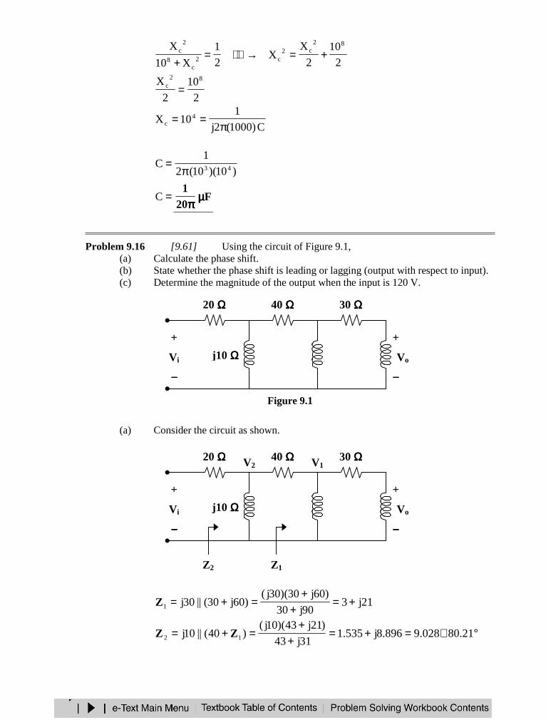
Problem 9.16 [9.61] Using the circuit of Figure 9.1,(a) Calculate the phase shift.(b) State whether the phase shift is leading or lagging (output with respect to input).(c) Determine the magnitude of the output when the input is 120 V.
Figure 9.1
(a) Consider the circuit as shown.
21j390j30
)60j30)(30j()60j30(||30j1 +=
++
=+=Z
°∠=+=+
+=+= 21.80028.9896.8j535.1
31j43
)21j43)(10j()40(||10j 12 ZZ
20 ΩΩΩΩ 30 ΩΩΩΩ
j10 ΩΩΩΩ j60 ΩΩΩΩ+
Vi
−−−−
+
Vo
−−−−
40 ΩΩΩΩ
j30 ΩΩΩΩ
V2
Z2
V1
Z1
20 ΩΩΩΩ 30 ΩΩΩΩ
j10 ΩΩΩΩ j60 ΩΩΩΩ+
Vi
−−−−
+
Vo
−−−−
40 ΩΩΩΩ
j30 ΩΩΩΩ
Let °∠= 01iV .
896.8j535.21
)01)(21.80028.9(
20 i2
22 +
°∠°∠=
+= V
ZZ
V
°∠= 77.573875.02V
°∠°∠°∠
=++
=+
=03.2685.47
)77.573875.0)(87.81213.21(
21j43
21j3
40 221
11 VV
ZZ
V
°∠= 61.1131718.01V
111o )j2(5
2
2j1
2j
60j30
60jVVVV +=
+=
+=
)6.1131718.0)(56.268944.0(o °∠°∠=V
°∠= 2.1401536.0oV
Therefore, the phase shift is °°°°2.140
(b) The phase shift is leading .
(c) If V120i =V , then
°∠=°∠= 2.14043.18)2.1401536.0)(120(oV V
and the magnitude is V43.18 .
CHAPTER 10 - SINUSOIDAL STEADY-STATE ANALYSIS
List of topics for this chapter :Nodal AnalysisMesh AnalysisSuperposition TheoremSource TransformationThevenin and Norton Equivalent CircuitsAC Op Amp Circuits
NODAL ANALYSIS
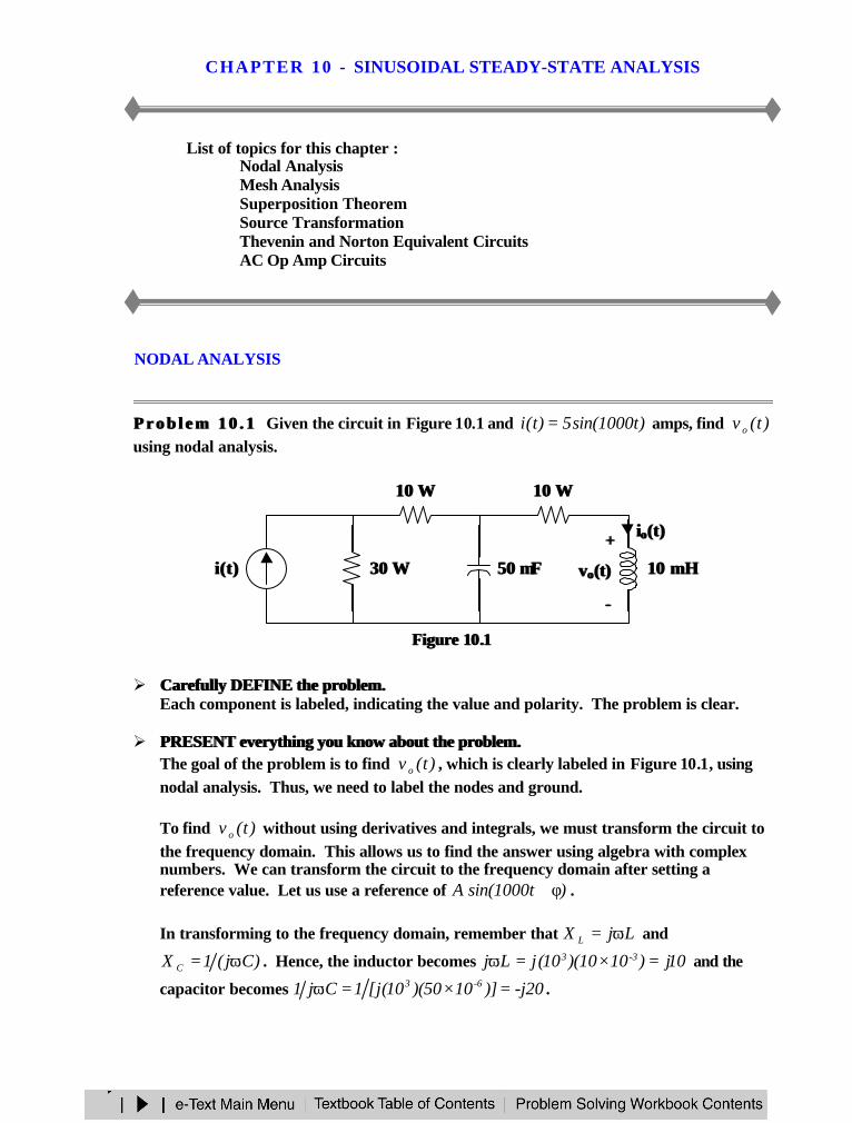
P r o b l e m 1 0 . 1P r o b l e m 1 0 . 1 Given the circuit in Figure 10.1 and )t1000sin(5)t(i = amps, find )t(v o
using nodal analysis.
Figure Figure 1010..11
Ø Carefully DEFINE the problem.Carefully DEFINE the problem.Each component is labeled, indicating the value and polarity. The problem is clear.
Ø PRESENT everything you know about the problem.PRESENT everything you know about the problem.The goal of the problem is to find )t(v o , which is clearly labeled in Figure 10.1, usingnodal analysis. Thus, we need to label the nodes and ground.
To find )t(v o without using derivatives and integrals, we must transform the circuit tothe frequency domain. This allows us to find the answer using algebra with complexnumbers. We can transform the circuit to the frequency domain after setting areference value. Let us use a reference of )t1000sin(A φ+ .
In transforming to the frequency domain, remember that LjX L ω= and
)Cj(1X C ω= . Hence, the inductor becomes 10j)1010)(10(jLj 3-3 =×=ω and the
capacitor becomes -j20)]1050)(10(j[1Cj1 6-3 =×=ω .
30 30 ΩΩ
10 10 ΩΩ
50 50 µµFF 10 mH10 mH
++
vvoo(t)(t)
−−
10 10 ΩΩ
i(t)i(t)
iioo(t)(t)
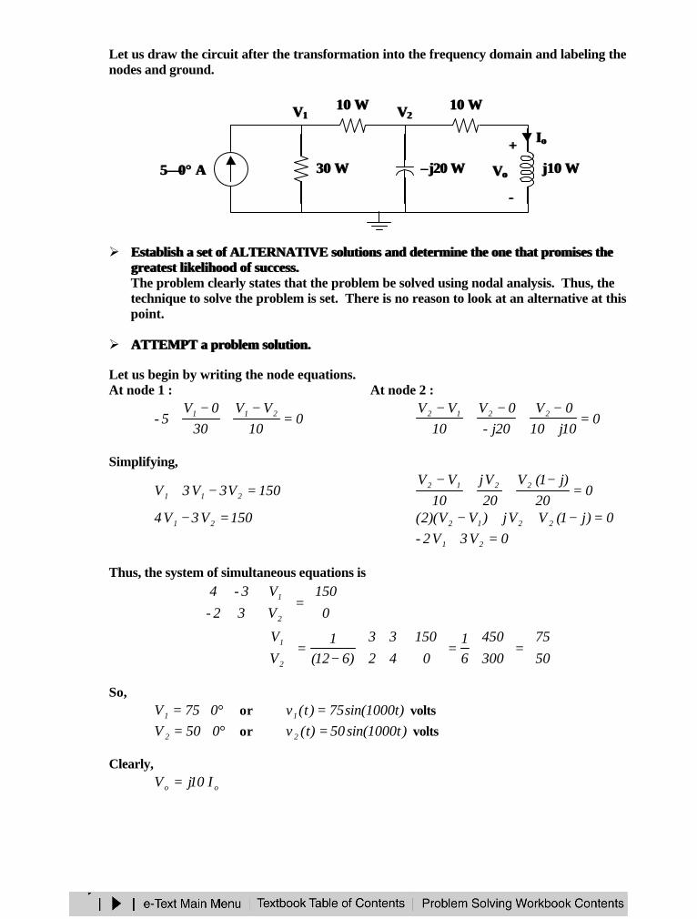
Let us draw the circuit after the transformation into the frequency domain and labeling thenodes and ground.
Ø Establish a set of ALTERNATIVE solutions and determine the one that promises theEstablish a set of ALTERNATIVE solutions and determine the one that promises thegreatest likelihood of success.greatest likelihood of success.The problem clearly states that the problem be solved using nodal analysis. Thus, thetechnique to solve the problem is set. There is no reason to look at an alternative at thispoint.
Ø ATTEMPT a problem solution.ATTEMPT a problem solution.
Let us begin by writing the node equations.At node 1 : At node 2 :
010
VV30
0V5- 211 =
−+
−+ 0
10j100V
20j-0V
10VV 2212 =
+−
+−
+−
Simplifying,
150V3V3V 211 =−+ 020
)j1(V20Vj
10VV 2212 =
−++
−
150V3V4 21 =− 0)j1(VVj)VV)(2( 2212 =−++−0V3V2- 21 =+
Thus, the system of simultaneous equations is
=
0
150
V
V
32-
3-4
2
1
=
=
−=
50
75
300
450
61
0
150
42
33
)612(1
V
V
2
1
So,°∠= 075V1 or )t1000sin(75)t(v1 = volts
°∠= 050V 2 or )t1000sin(50)t(v 2 = volts
Clearly,
oo I10jV =
55∠∠00°° A A 30 30 ΩΩ
10 10 ΩΩ
–– j20 j20 ΩΩ j10 j10 ΩΩ++
VVoo
−−
10 10 ΩΩVV11 VV22
IIoo
and )45-2)(5.2()j1)(5.2(20
)j1)(50()j1)(10(
5010j10
VI 2
o °∠=−=−
=+
=+
= amps
Hence,
)45-2)(5.2)(9010(I10jV oo °∠°∠== °∠=°∠= 4536.3545225 volts
Therefore,)45t1000sin(36.35)t(v o °+= volts
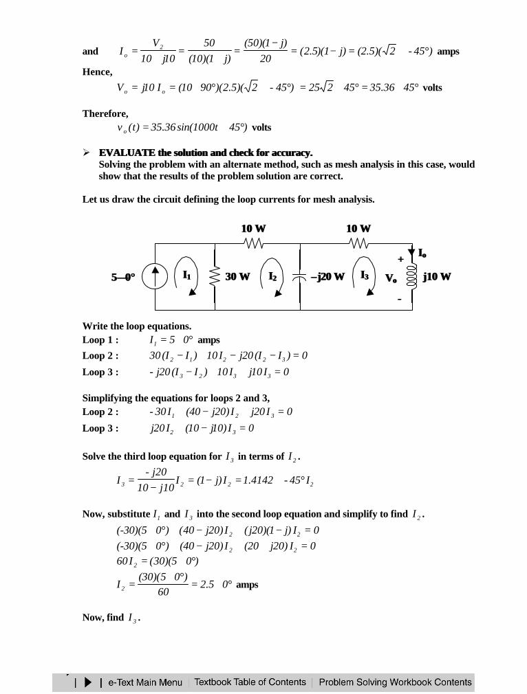
Ø EVALUATE the solution and check for accuracy.EVALUATE the solution and check for accuracy.Solving the problem with an alternate method, such as mesh analysis in this case, wouldshow that the results of the problem solution are correct.
Let us draw the circuit defining the loop currents for mesh analysis.
Write the loop equations.Loop 1 : °∠= 05I1 amps
Loop 2 : 0)II(20jI10)II(30 32212 =−−+−Loop 3 : 0I10jI10)II(20j- 3323 =++−
Simplifying the equations for loops 2 and 3,Loop 2 : 0I20jI)20j40(I30- 321 =+−+Loop 3 : 0I)10j10(I20j 32 =−+
Solve the third loop equation for 3I in terms of 2I .
2223 I45-4142.1I)j1(Ij1010
j20-I °∠=−=
−=
Now, substitute 1I and 3I into the second loop equation and simplify to find 2I .
0I)j1)(20j(I)20j40()0(-30)(5 22 =−+−+°∠0I)20j20(I)20j40()0(-30)(5 22 =++−+°∠
)05)(30(I60 2 °∠=
°∠=°∠
= 05.260
)05)(30(I 2 amps
Now, find 3I .
55∠∠00°° 30 30 ΩΩ
10 10 ΩΩ
–– j20 j20 ΩΩ j10 j10 ΩΩ++
VVoo
−−
10 10 ΩΩ
IIoo
II22II11 II33
°∠=°∠°∠=°∠= 45-536.3)05.2)(45-4142.1(I)45-4142.1(I 23 amps
Clearly, °∠== 45-536.3II 3o amps.
Evidently,°∠=°∠°∠== 4536.35)45-536.3)(9010(I10jV oo volts
and )45t1000sin(36.35)t(v o °+= volts
This answer is the same as the answer obtained using nodal analysis. Our check foraccuracy was successful.
Ø Has the problem been solved SATISFACTORILY? If so, present the solution; if not,then return “ALTERNATIVE solutions” and continue through the process again.This problem has been solved satisfactorily.
=)t(v o volts)45t1000sin(36.35 °°++
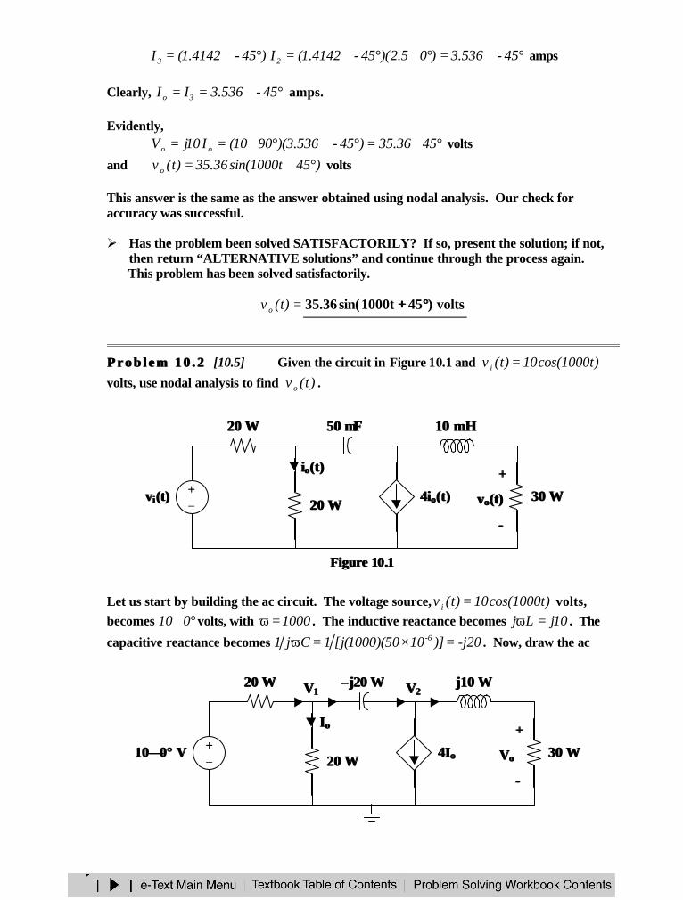
P r o b l e m 1 0 . 2P r o b l e m 1 0 . 2 [10.5] Given the circuit in Figure 10.1 and )t1000cos(10)t(v i =volts, use nodal analysis to find )t(v o .
Figure Figure 1010..11
Let us start by building the ac circuit. The voltage source, )t1000cos(10)t(v i = volts,becomes °∠010 volts, with 1000=ω . The inductive reactance becomes 10jLj =ω . The
capacitive reactance becomes -j20)]1050)(1000(j[1Cj1 6- =×=ω . Now, draw the ac
20 20 ΩΩ
+−
vvii (t)(t)
50 50 µµFF 10 mH10 mH
20 20 ΩΩ 30 30 ΩΩ++
vvoo(t)(t)
−−
4i4ioo(t)(t)
iioo(t)(t)
VV22VV1120 20 ΩΩ
+−
–– j20 j20 ΩΩ j10 j10 ΩΩ
20 20 ΩΩ 30 30 ΩΩ++
VVoo
−−
4I4Ioo1010∠∠00°° V V
IIoo
circuit.
At node 1 : At node 2 :
20j-VV
20V
20V10 2111 −
+=−
10j30V
20V4
20j-VV 2121
++=
−
)VV(jVV10 2111 −+=− 21 V)8.0j6.0(V)j4-( +=+
21 Vj2jV)j2(10 +−+= 21 Vj4-8.0j6.0
V+
+=
Note that 20VI 1o = was substituted when writing the equation for node 2.
Substituting the equation for node 2 into the equation for node 1,
22 VjVj4-
)j8.06.0)(j2(10 −
+++
=
or2.26j6.0
170V 2 −
=
Clearly,
°∠=
−
+=
+= 26.70154.6
2.26j6.0170
j33
V10j30
30V 2o volts
With a reference of )t1000cos(A φ+ ,=)t(v o volts)26.70t1000cos(154.6 °°++
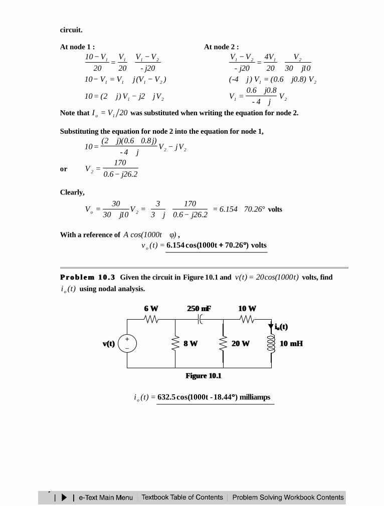
P r o b l e m 1 0 . 3P r o b l e m 1 0 . 3 Given the circuit in Figure 10.1 and )t1000cos(20)t(v = volts, find
)t(i o using nodal analysis.
Figure Figure 1010..11
=)t(i o milliamps)18.44-t1000cos(5.632 °°
8 8 ΩΩ
6 6 ΩΩ
10 mH10 mH
10 10 ΩΩ
20 20 ΩΩv(t)v(t) +−
iioo(t)(t)
250 250 µµFF
MESH ANALYSIS
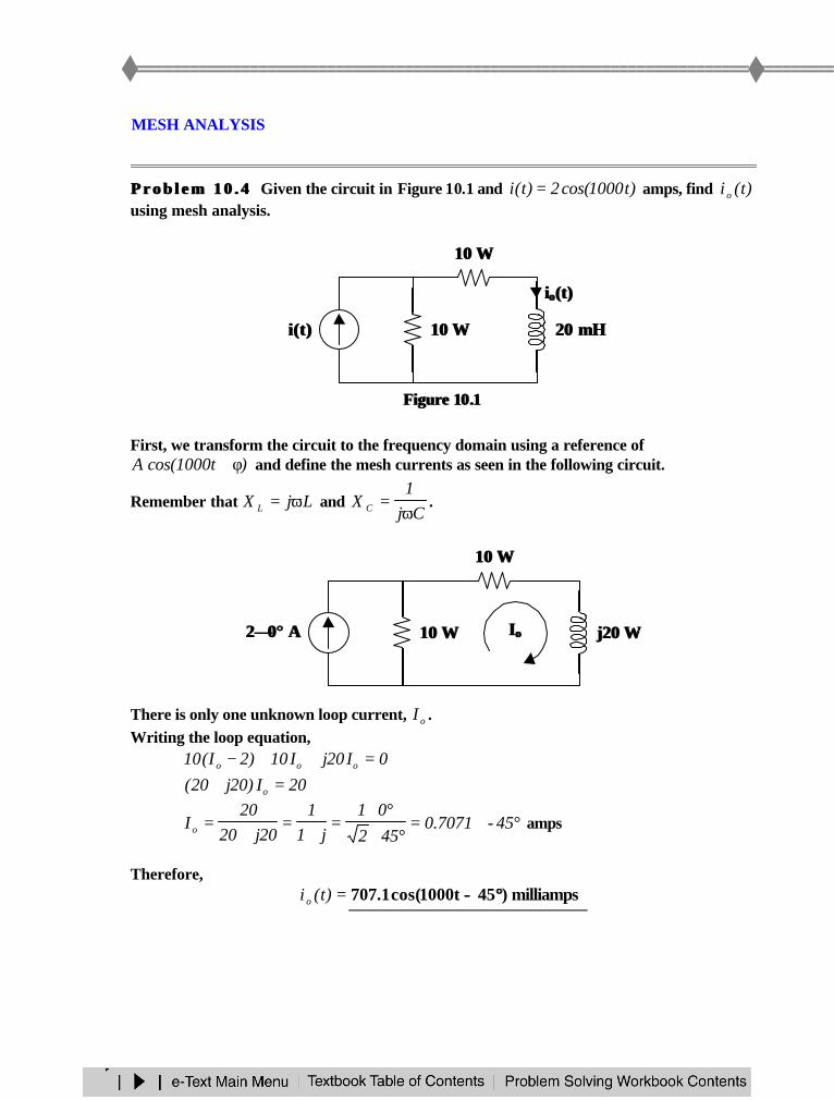
P r o b l e m 1 0 . 4P r o b l e m 1 0 . 4 Given the circuit in Figure 10.1 and )t1000cos(2)t(i = amps, find )t(i o
using mesh analysis.
Figure Figure 1010..11
First, we transform the circuit to the frequency domain using a reference of)t1000cos(A φ+ and define the mesh currents as seen in the following circuit.
Remember that LjX L ω= and Cj
1X C ω
= .
There is only one unknown loop current, oI .Writing the loop equation,
0I20jI10)2I(10 ooo =++−20I)20j20( o =+
°∠=°∠
°∠=
+=
+= 45-7071.0
452
01j1
120j20
20I o amps
Therefore,=)t(i o milliamps)45t1000cos(1.707 °°−−
i(t)i(t)
10 10 ΩΩ
10 10 ΩΩ 20 20 mHmH
iioo(t)(t)
IIoo
10 10 ΩΩ
10 10 ΩΩ j20 j20 ΩΩ22∠∠00°° A A
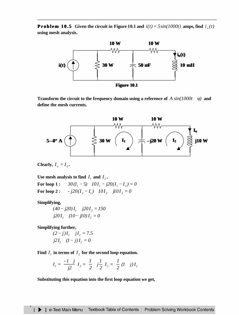
P r o b l e m 1 0 . 5P r o b l e m 1 0 . 5 Given the circuit in Figure 10.1 and )t1000sin(5)t(i = amps, find )t(i o
using mesh analysis.
Figure Figure 1010..11
Transform the circuit to the frequency domain using a reference of )t1000sin(A φ+ anddefine the mesh currents.
Clearly, 2o II = .
Use mesh analysis to find 1I and 2I .
For loop 1 : 0)II(20jI10)5I(30 2111 =−−+−For loop 2 : 0I10jI10)II(j20- 2212 =++−
Simplifying,150I20jI)20j40( 21 =+−0I)10j10(I20j 21 =−+
Simplifying further,5.7IjI)j2( 21 =+−
0I)j1(I2j 21 =−+
Find 1I in terms of 2I for the second loop equation.
2221 I)j1(21
I21
j21
I2j
j1-I +
=
+=
+
=
Substituting this equation into the first loop equation we get,
30 30 ΩΩ
10 10 ΩΩ
50 50 µµFF 10 10 mHmH
10 10 ΩΩ
i(t)i(t)
iioo(t)(t)
30 30 ΩΩ
10 10 ΩΩ
–– j20 j20 ΩΩ j10 j10 ΩΩ
10 10 ΩΩ
II11 II2255∠∠00°° A A
IIoo
5.7IjI2
j1)j2( 22 =+
+
−
15I2jI)j1()j2( 22 =++−15I)3j3( 2 =+
°∠=°∠
°∠=
+=
+= 45-536.3
452
05j1
53j3
15I 2
Hence,°∠= 45-536.3I o amps
Therefore, =)t(i o amps)45t1000sin(536.3 °°−−
SUPERPOSITION THEOREM
The superposition theorem applies to ac circuits the same as it does for dc circuits.This theorem is important if the circuit has sources operating at different frequencies.Since the impedances depend on frequency, we must have a different frequency-domaincircuit for each source. The total response is obtained by adding the individual responses inthe time domain.
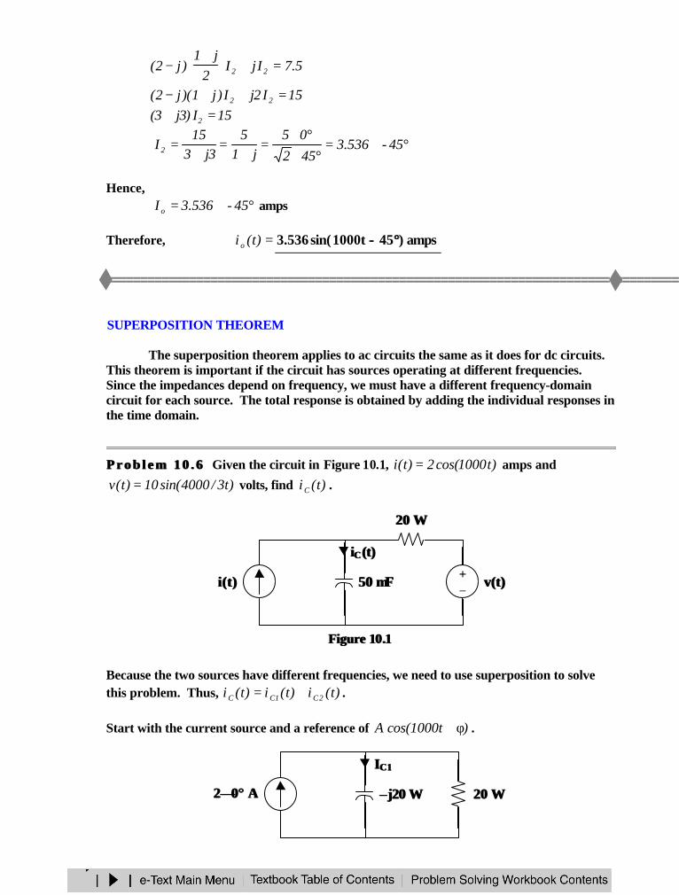
P r o b l e m 1 0 . 6P r o b l e m 1 0 . 6 Given the circuit in Figure 10.1, )t1000cos(2)t(i = amps and
)t3/4000sin(10)t(v = volts, find )t(iC .
Figure Figure 1010..11
Because the two sources have different frequencies, we need to use superposition to solvethis problem. Thus, )t(i)t(i)t(i 2C1CC += .
Start with the current source and a reference of )t1000cos(A φ+ .
+−
v(t)v(t)i(t)i(t) 50 50 µµFF
iiCC (t)(t)
20 20 ΩΩ
–– j20 j20 ΩΩ
IIC1C1
22∠∠00°° A A 20 20 ΩΩ
Using current division,
°∠=°∠=+=+
=−
=
−= 454142.1452j1
2)j1)(2(
j12
)2(20j20
20I 1C amps
Hence,)45t1000cos(4142.1)t(i 1C °+= amps
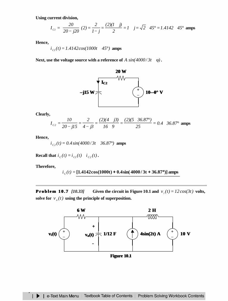
Next, use the voltage source with a reference of )t3/4000sin(A φ+ .
Clearly,
°∠=°∠
=++
=−
=−
= 87.364.025
)87.365)(2(916
)3j4)(2(3j4
215j20
10I 2C amps
Hence,)87.36t3/4000sin(4.0)t(i 2C °+= amps
Recall that )t(i)t(i)t(i 2C1CC += .
Therefore,=)t(iC amps)]87.36t3/4000sin(4.0)t1000cos(4142.1[ °°++++
P r o b l e m 1 0 . 7P r o b l e m 1 0 . 7 [10.33] Given the circuit in Figure 10.1 and )t3cos(12)t(v i = volts,
solve for )t(v o using the principle of superposition.
Figure Figure 1010..11
+−
20 20 ΩΩ
1010∠∠00°° V V
IIC2C2
–– j15 j15 ΩΩ
1/12 F1/12 F+−
vv ii (t)(t)
6 6 ΩΩ 2 H2 H
4sin(2t) A4sin(2t) A +−
10 V10 V
++
vvoo(t)(t)
−−
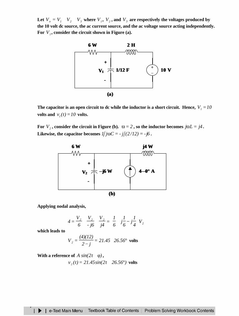
Let 321o VVVV ++= where 1V , 2V , and 3V are respectively the voltages produced bythe 10 volt dc source, the ac current source, and the ac voltage source acting independently.For 1V , consider the circuit shown in Figure (a).
The capacitor is an open circuit to dc while the inductor is a short circuit. Hence, 10V1 =volts and 10)t(v1 = volts.
For 2V , consider the circuit in Figure (b). 2=ω , so the inductor becomes 4jLj =ω .
Likewise, the capacitor becomes 6j-)12/2(j-Cj1 ==ω .
Applying nodal analysis,
2222 V
41
j61
j61
4jV
6j-V
6V
4
−+=++=
which leads to
°∠=−
= 56.2645.21j2)12)(4(
V 2 volts
With a reference of )t2sin(A φ+ ,)56.26t2sin(45.21)t(v 2 °+= volts
1/12 F1/12 F
6 6 ΩΩ 2 H2 H
+−
10 V10 V
++
VV11
−−
((a)a)
((b)b)
–– j6 j6 ΩΩ
6 6 ΩΩ j4 j4 ΩΩ
++
VV22
−−
44∠∠00°° A A
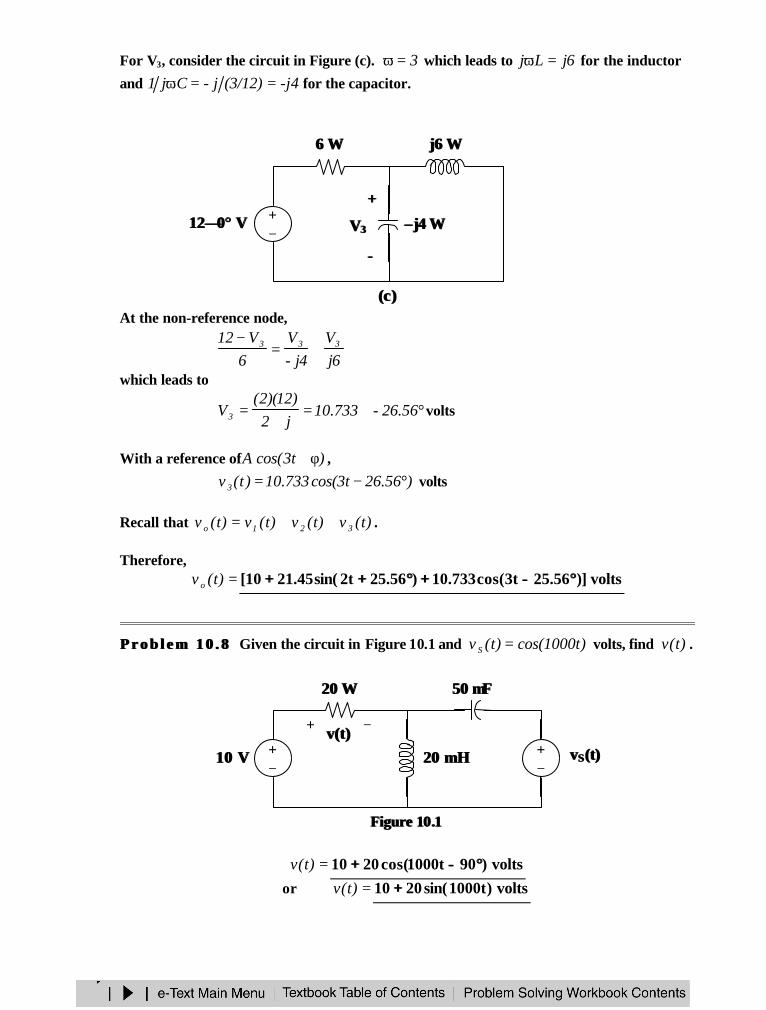
For V3, consider the circuit in Figure (c). 3=ω which leads to 6jLj =ω for the inductor
and -j4(3/12)j-Cj1 ==ω for the capacitor.
At the non-reference node,
6jV
4j-V
6V12 333 +=
−
which leads to
°∠=+
= 56.26-733.10j2)12)(2(
V3 volts
With a reference of )t3cos(A φ+ ,
)56.26t3cos(733.10)t(v 3 °−= volts
Recall that )t(v)t(v)t(v)t(v 321o ++= .
Therefore,=)t(v o volts)]56.25t3cos(733.10)56.25t2sin(45.2110[ °°−−++°°++++
P r o b l e m 1 0 . 8P r o b l e m 1 0 . 8 Given the circuit in Figure 10.1 and )t1000cos()t(v S = volts, find )t(v .
Figure Figure 1010..11
=)t(v volts)90t1000cos(2010 °°−−++or =)t(v volts)t1000sin(2010 ++
((c)c)
–– j4 j4 ΩΩ+−
6 6 ΩΩ j6 j6 ΩΩ
++
VV33
−−
1212∠∠00°° V V
+−
10 V10 V +−
vvSS (t)(t)
+ −v(t)v(t)
20 20 ΩΩ 50 50 µµFF
20 20 mHmH
SOURCE TRANSFORMATION
Source transformation in the frequency domain involves transforming a voltagesource in series with an impedance to a current source in parallel with an impedance or viceversa. We must keep the following relationship in mind when performing sourcetransformations.
SSS IZV =S
SS Z
VI =
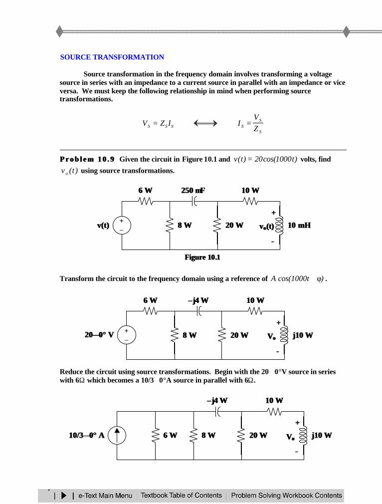
P r o b l e m 1 0 . 9P r o b l e m 1 0 . 9 Given the circuit in Figure 10.1 and )t1000cos(20)t(v = volts, find
)t(v o using source transformations.
Figure Figure 1010..11
Transform the circuit to the frequency domain using a reference of )t1000cos(A φ+ .
Reduce the circuit using source transformations. Begin with the 20∠0°V source in serieswith 6Ω which becomes a 10/3∠0°A source in parallel with 6Ω.
8 8 ΩΩ
6 6 ΩΩ
10 mH10 mH
10 10 ΩΩ
20 20 ΩΩv(t)v(t) +−
250 250 µµFF
++
vvoo(t)(t)
−−
8 8 ΩΩ
6 6 ΩΩ
j10 j10 ΩΩ
10 10 ΩΩ
20 20 ΩΩ+−
–– j4 j4 ΩΩ
++
VVoo
−−
2020∠∠00°° V V
8 8 ΩΩ j10 j10 ΩΩ
10 10 ΩΩ
20 20 ΩΩ
–– j4 j4 ΩΩ
++
VVoo
−−
10/310/3∠∠00°° A A 6 6 ΩΩ
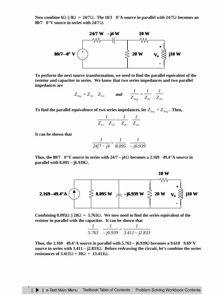
Now combine 6Ω || 8Ω = 24/7Ω. The 10/3∠0°A source in parallel with 24/7Ω becomes an80/7∠0°V source in series with 24/7Ω.
To perform the next source transformation, we need to find the parallel equivalent of theresistor and capacitor in series. We know that two series impedances and two parallelimpedances are
2S1SSeq ZZZ += and2P1PPeq Z
1Z1
Z1
+=
To find the parallel equivalence of two series impedances, let PeqSeq ZZ = . Then,
2P1P2S1S Z1
Z1
ZZ1
+=+
It can be shown that
j6.939-1
095.81
4j7241
+=−
Thus, the 80/7∠0°V source in series with 24/7 – j4Ω becomes a 2.169∠49.4°A source inparallel with 8.095 – j6.939Ω.
Combining 8.095Ω || 20Ω = 5.763Ω. We now need to find the series equivalent of theresistor in parallel with the capacitor. It can be shown that
833.2j411.31
j6.939-1
763.51
−=+
Thus, the 2.169∠49.4°A source in parallel with 5.763 – j6.939Ω becomes a 9.618∠9.69°Vsource in series with 3.411 – j2.833Ω. Before redrawing the circuit, let’s combine the seriesresistances of 3.411Ω + 10Ω = 13.411Ω.
–– j6.939 j6.939 ΩΩ j10 j10 ΩΩ
10 10 ΩΩ
20 20 ΩΩ++
VVoo
−−
8.095 8.095 ΩΩ2.1692.169∠∠49.449.4°°AA
24/7 24/7 ΩΩ
j10 j10 ΩΩ
10 10 ΩΩ
20 20 ΩΩ+−
–– j4 j4 ΩΩ
80/780/7∠∠00°° V V
++
VVoo
−−
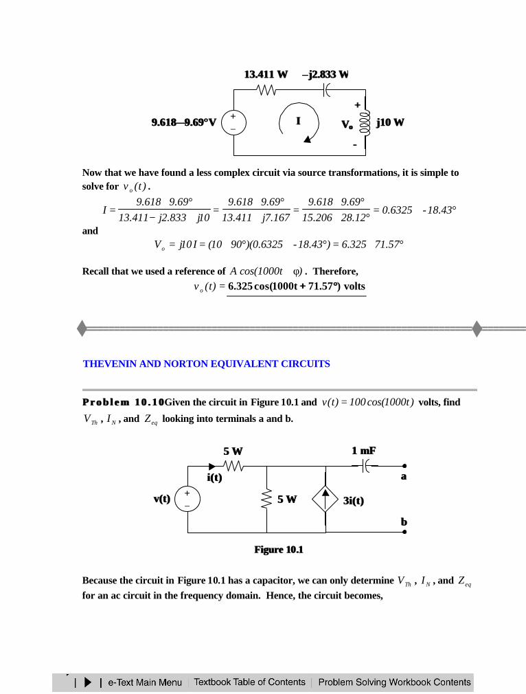
Now that we have found a less complex circuit via source transformations, it is simple tosolve for )t(v o .
°∠=°∠
°∠=
+°∠
=+−°∠
= 43.18-6325.012.28206.15
69.9618.9167.7j411.13
69.9618.910j833.2j411.13
69.9618.9I
and°∠=°∠°∠== 57.71325.6)43.18-6325.0)(9010(I10jVo
Recall that we used a reference of )t1000cos(A φ+ . Therefore,=)t(v o volts)57.71t1000cos(325.6 °°++
THEVENIN AND NORTON EQUIVALENT CIRCUITS
P r o b l e m 1 0 . 1 0P r o b l e m 1 0 . 1 0 Given the circuit in Figure 10.1 and )t1000cos(100)t(v = volts, find
ThV , NI , and eqZ looking into terminals a and b.
Figure Figure 1010..11
Because the circuit in Figure 10.1 has a capacitor, we can only determine ThV , NI , and eqZfor an ac circuit in the frequency domain. Hence, the circuit becomes,
–– j2.833 j2.833 ΩΩ13.411 13.411 ΩΩ
j10 j10 ΩΩ+−
9.6189.618∠∠9.699.69°°VV II++
VVoo
−−
3i(t)3i(t)+−
5 5 ΩΩ
v(t)v(t)
i(t)i(t)
5 5 ΩΩ
1 mF1 mF
aa
bb
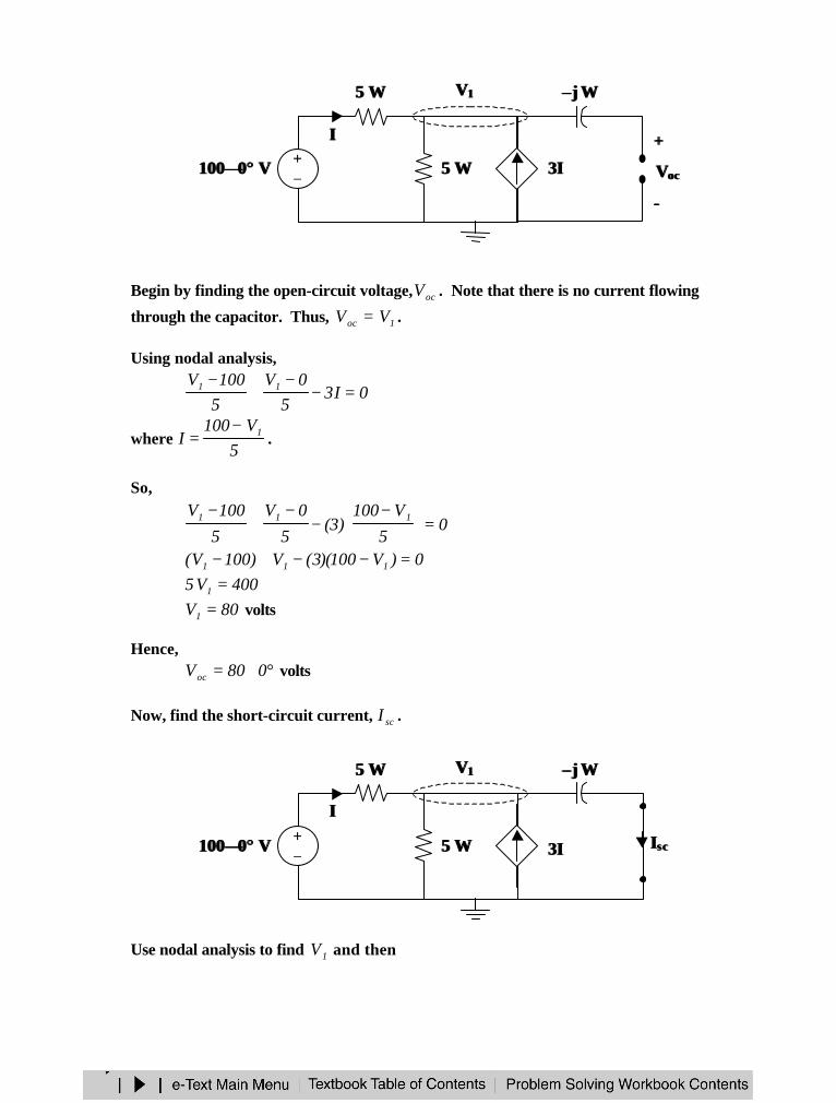
Begin by finding the open-circuit voltage, ocV . Note that there is no current flowing
through the capacitor. Thus, 1oc VV = .
Using nodal analysis,
0I35
0V5100V 11 =−
−+
−
where 5
V100I 1−
= .
So,
05
V100)3(
5
0V
5
100V 111 =
−
−−
+−
0)V100)(3(V)100V( 111 =−−+−400V5 1 =
80V1 = volts
Hence,°∠= 080Voc volts
Now, find the short-circuit current, scI .
Use nodal analysis to find 1V and then
+−
5 5 ΩΩ
II
5 5 ΩΩ
–– j j ΩΩ
3I 3I100100∠∠00°° V V
VV11
++
VVococ
−−
+−
5 5 ΩΩ
II
5 5 ΩΩ
–– j j ΩΩ
3I 3I100100∠∠00°° V V
VV11
IIscsc
j-V
I 1sc =
Writing the nodal equation,
0j-
0VI3
50V
5100V 111 =
−+−
−+
−
where 5
V100I 1−
= .
So,
0Vj5
V100)3(
5
0V
5
100V1
111 =+
−
−−
+−
0V5j)V100)(3(V)100V( 1111 =+−−+−400V)5j5( 1 =+
)j1)(40(2
)j1)(80(j1
805j5
400V1 −=
−=
+=
+=
Thus,
°∠=+=−
−== 45240)j1)(40(
j)j1)(40(
j-V
I 1sc amps
Finally,
°∠=°∠
°∠== 45-2
45240
080IV
Zsc
oceq ohms
Therefore,== ocTh VV °°∠∠080 or =)t(v Th volts)t1000cos(80
== scN II °°∠∠45240 or =)t(iN amps)45t1000cos(57.56 °°++
=eqZ °°∠∠ 45-2 or =eqZ ohms)j1( −−
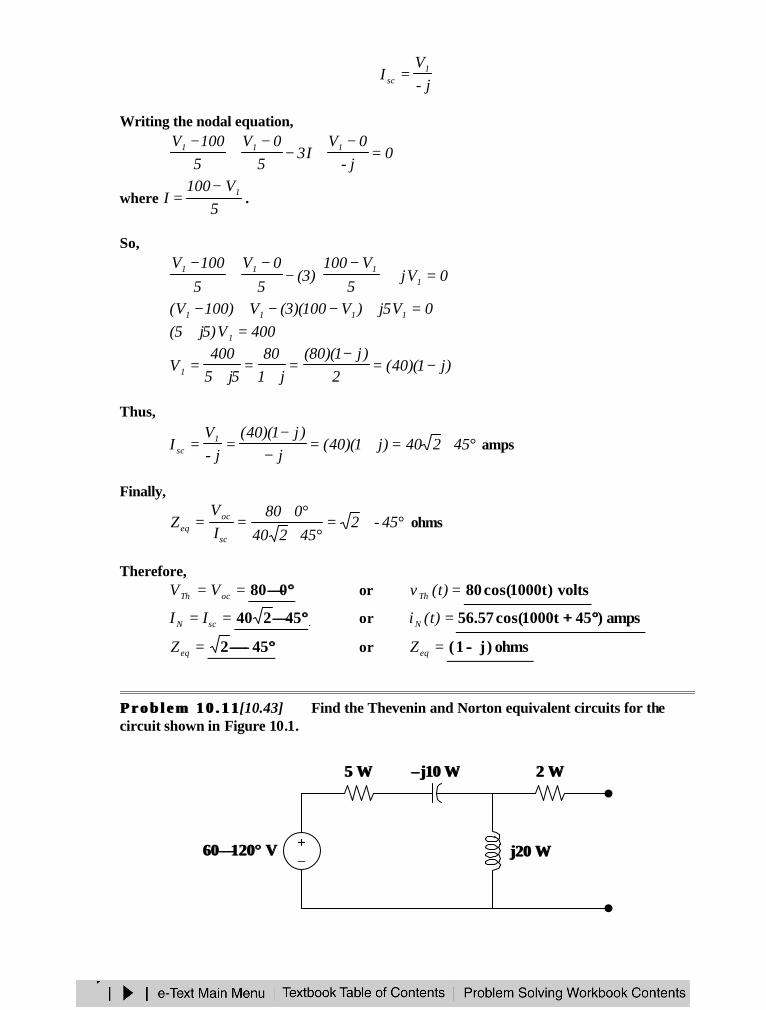
P r o b l e m 1 0 . 1 1P r o b l e m 1 0 . 1 1 [10.43] Find the Thevenin and Norton equivalent circuits for thecircuit shown in Figure 10.1.
5 5 ΩΩ –– j10 j10 ΩΩ
j20 j20 ΩΩ
2 2 ΩΩ
6060∠∠120120°° V V +−
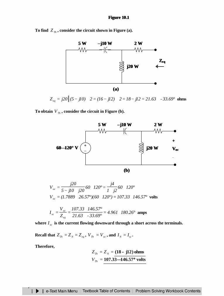
Figure Figure 1010..11
To find ThZ , consider the circuit shown in Figure (a).
°∠=−=+−=+−= 69.33-63.2112j182)12j16(2)10j5(20jZeq ohms
To obtain ThV , consider the circuit in Figure (b).
°∠+
=°∠+−
= 120602j1
4j12060
20j10j520j
Voc
°∠=°∠°∠= 57.14633.107)12060)(57.267889.1(Voc volts
°∠=°∠°∠
== 26.180961.469.33-63.2157.14633.107
ZV
Ieq
ocsc amps
where scI is the current flowing downward through a short across the terminals.
Recall that eqNTh ZZZ == , ocTh VV = , and scN II = .
Therefore,== NTh ZZ ohms)12j18( −−
=ThV volts57.14633.107 °°∠∠
ZZeqeq
(a)(a)
5 5 ΩΩ –– j10 j10 ΩΩ
j20 j20 ΩΩ
2 2 ΩΩ
(b)(b)
5 5 ΩΩ –– j10 j10 ΩΩ
j20 j20 ΩΩ
2 2 ΩΩ
6060∠∠120120°° V V +−
++
VVococ
−−
=NI amps26.180961.4 °°∠∠
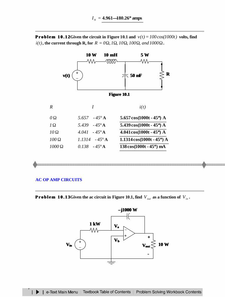
P r o b l e m 1 0 . 1 2P r o b l e m 1 0 . 1 2 Given the circuit in Figure 10.1 and )t1000cos(100)t(v = volts, find)t(i , the current through R, for ΩΩΩΩΩ= 1000and,100,10,1,0R .
Figure Figure 1010..11
R I )t(i
Ω0 °∠ 45-657.5 A A)45-1000tcos(657.5 °°Ω1 °∠ 45-439.5 A A)45-1000tcos(439.5 °°
Ω10 °∠ 45-041.4 A A)45-1000tcos(041.4 °°Ω100 °∠ 45-1314.1 A A)45-1000tcos(1314.1 °°Ω1000 °∠ 45-138.0 A mA)45-1000tcos(138 °°
AC OP AMP CIRCUITS
P r o b l e m 1 0 . 1 3P r o b l e m 1 0 . 1 3 Given the ac circuit in Figure 10.1, find outV as a function of inV .
+−
v(t)v(t)
10 10 ΩΩ 10 mH10 mH
50 50 µµFF
5 5 ΩΩ
RR
−+
VVaa
VVbb
–– j1000 j1000 ΩΩ
1 k1 kΩΩ
+−
VVinin
++
VVoutout
−−
10 10 ΩΩ
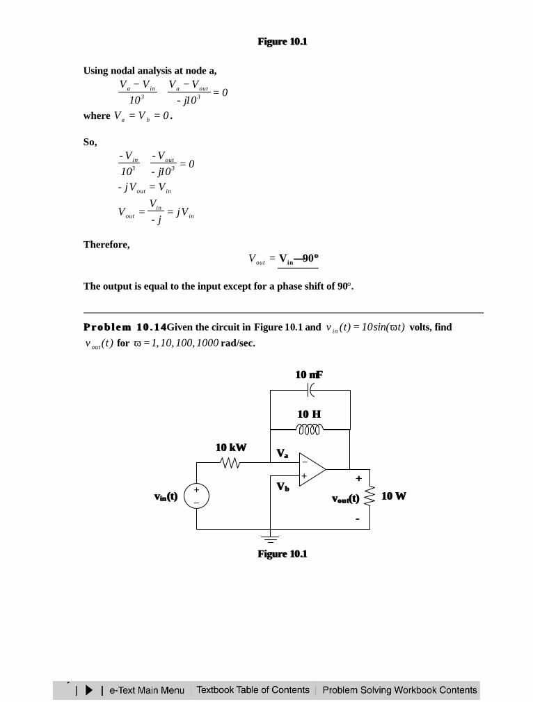
Figure Figure 1010..11
Using nodal analysis at node a,
010j-
VV10
VV3outa
3ina =
−+
−
where 0VV ba == .
So,
010j-V-
10V-
3out
3in =+
inout VVj- =
inin
out Vjj-
VV ==
Therefore,=outV °°∠∠90Vin
The output is equal to the input except for a phase shift of 90°.
P r o b l e m 1 0 . 1 4P r o b l e m 1 0 . 1 4 Given the circuit in Figure 10.1 and )tsin(10)t(v in ω= volts, find
)t(v out for 1000,100,10,1=ω rad/sec.
Figure Figure 1010..11
−+
VVaa
VVbb
10 10 µµFF
10 k10 kΩΩ
+−
vv iinn (t)(t)
++
vvoutout(t)(t)
−−
10 10 ΩΩ
10 H10 H
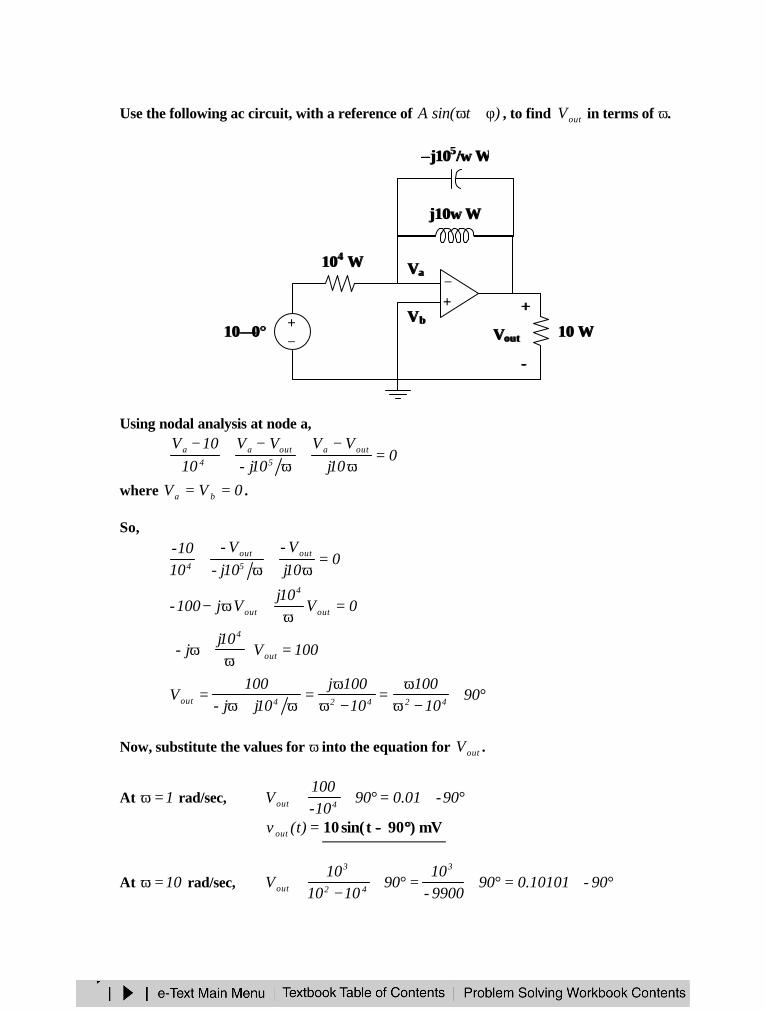
Use the following ac circuit, with a reference of )tsin(A φ+ω , to find outV in terms of ω.
Using nodal analysis at node a,
010j
VV10j-
VV10
10V outa5
outa4
a =ω
−+
ω−
+−
where 0VV ba == .
So,
010jV-
10j-V-
1010- out
5out
4 =ω
+ω
+
0V10j
Vj100- out
4
out =ω
+ω−
100V10j
j- out
4
=
ω+ω
°∠−ω
ω=
−ωω
=ω+ω
= 9010
10010
100j10jj-
100V 42424out
Now, substitute the values for ω into the equation for outV .
At 1=ω rad/sec, °∠=°∠≅ 90-01.09010-100
V 4out
=)t(v out mV)90tsin(10 °°−−
At 10=ω rad/sec, °∠=°∠=°∠−
≅ 90-10101.0909900-10
901010
10V
3
42
3
out
10 10 ΩΩ
−+
VVaa
VVbb
–– j10j1055 //ωω ΩΩ
101044 ΩΩ
+−
++
VVoutout
−−
j10j10ωω ΩΩ
1010∠∠00°°
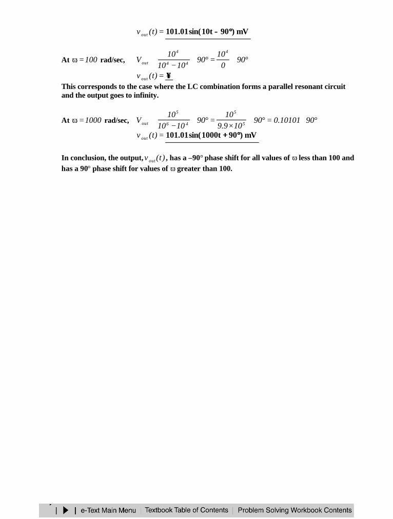
=)t(v out mV)90t10sin(01.101 °°−−
At 100=ω rad/sec, °∠=°∠−
≅ 900
1090
101010
V4
44
4
out
=)t(v out ∞∞This corresponds to the case where the LC combination forms a parallel resonant circuitand the output goes to infinity.
At 1000=ω rad/sec, °∠=°∠×
=°∠−
≅ 9010101.090109.9
1090
101010
V 5
5
46
5
out
=)t(v out mV)90t1000sin(01.101 °°++
In conclusion, the output, )t(v out , has a –90° phase shift for all values of ω less than 100 andhas a 90° phase shift for values of ω greater than 100.
CHAPTER 11 - AC POWER ANALYSIS
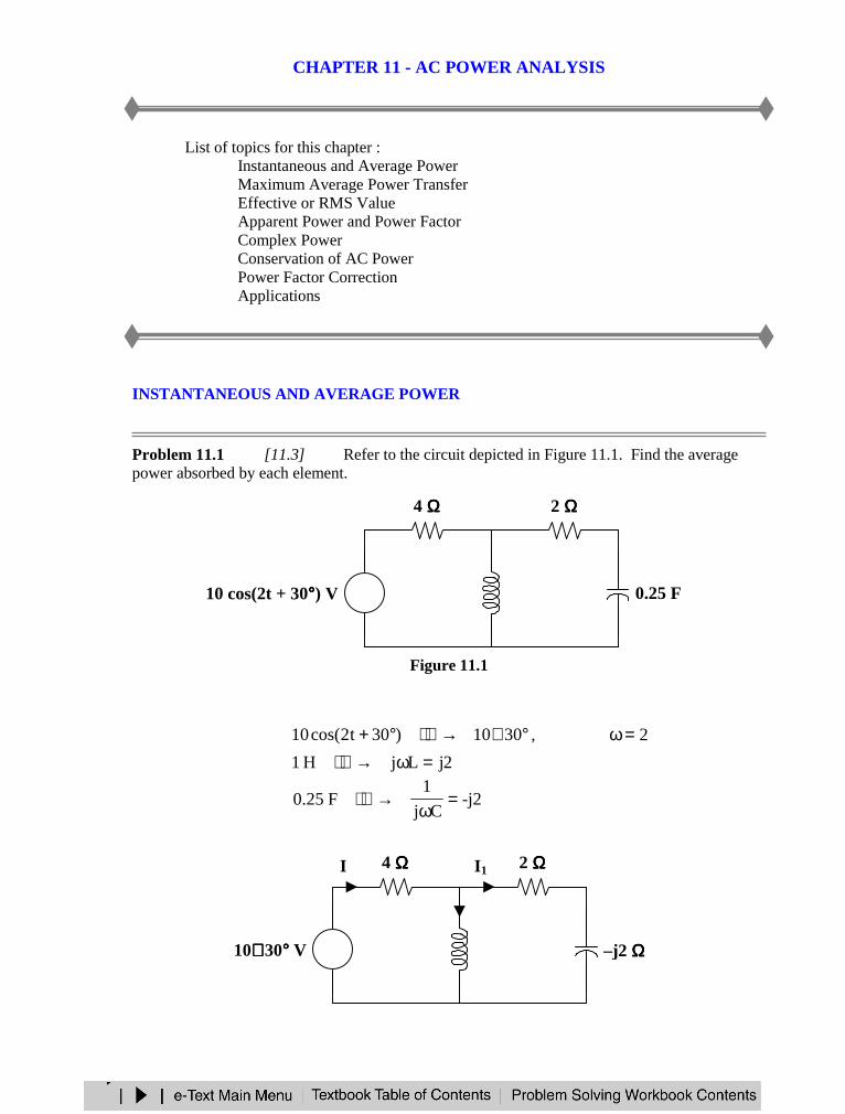
List of topics for this chapter :Instantaneous and Average PowerMaximum Average Power TransferEffective or RMS ValueApparent Power and Power FactorComplex PowerConservation of AC PowerPower Factor CorrectionApplications
INSTANTANEOUS AND AVERAGE POWER
Problem 11.1 [11.3] Refer to the circuit depicted in Figure 11.1. Find the averagepower absorbed by each element.
Figure 11.1
°∠→°+ 3010)30t2cos(10 , 2=ω2jLjH1 =ω→
-j2Cj
1F25.0 =
ω→
j2 ΩΩΩΩ –j2 ΩΩΩΩ
2 ΩΩΩΩ4 ΩΩΩΩ
10∠∠∠ ∠ 30°°°° V +−
I1
I2
I
1 H 0.25 F
2 ΩΩΩΩ4 ΩΩΩΩ
+−
10 cos(2t + 30°°°°) V
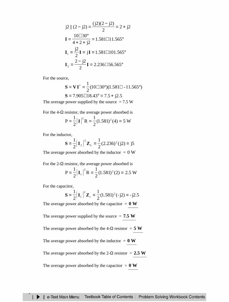
2j22
)2j2)(2j()2j2(||2j +=
−=−
°∠=++°∠
= 565.11581.12j24
3010I
°∠=== 565.101581.1j2
2j1 III
°∠=−
= 565.56236.22
2j22 II
For the source,
)565.11-581.1)(3010(2
1* °∠°∠== IVS
5.2j5.718.43905.7 +=°∠=SThe average power supplied by the source = 7.5 W
For the 4-Ω resistor, the average power absorbed is
=== )4()581.1(2
1R
2
1P 22
I W5
For the inductor,
5j)2j()236.2(2
1
2
12
L
2
2 === ZIS
The average power absorbed by the inductor = W0
For the 2-Ω resistor, the average power absorbed is
=== )2()581.1(2
1R
2
1P 2
2
1I W5.2
For the capacitor,
5.2j-)2j-()581.1(2
1
2
12
c
2
1 === ZIS
The average power absorbed by the capacitor = W0
The average power supplied by the source = W5.7
The average power absorbed by the 4-Ω resistor = W5
The average power absorbed by the inductor = W0
The average power absorbed by the 2-Ω resistor = W5.2
The average power absorbed by the capacitor = W0
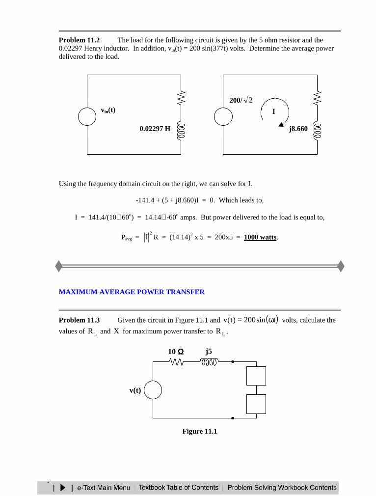
Problem 11.2 The load for the following circuit is given by the 5 ohm resistor and the0.02297 Henry inductor. In addition, vin(t) = 200 sin(377t) volts. Determine the average powerdelivered to the load.
Using the frequency domain circuit on the right, we can solve for I.
-141.4 + (5 + j8.660)I = 0. Which leads to,
I = 141.4/(10∠ 60o) = 14.14∠ -60o amps. But power delivered to the load is equal to,
Pavg = 2
I R = (14.14)2 x 5 = 200x5 = 1000 watts.
MAXIMUM AVERAGE POWER TRANSFER
Problem 11.3 Given the circuit in Figure 11.1 and ( )tsin200)t(v ω= volts, calculate the
values of LR and X for maximum power transfer to LR .
Figure 11.1
+−v(t)
10 ΩΩΩΩ j5
jX
RL
−−−−+ vin(t)
5 ΩΩΩΩ
0.02297 H−−−−+
200/ 2 5 ΩΩΩΩ
j8.660
I
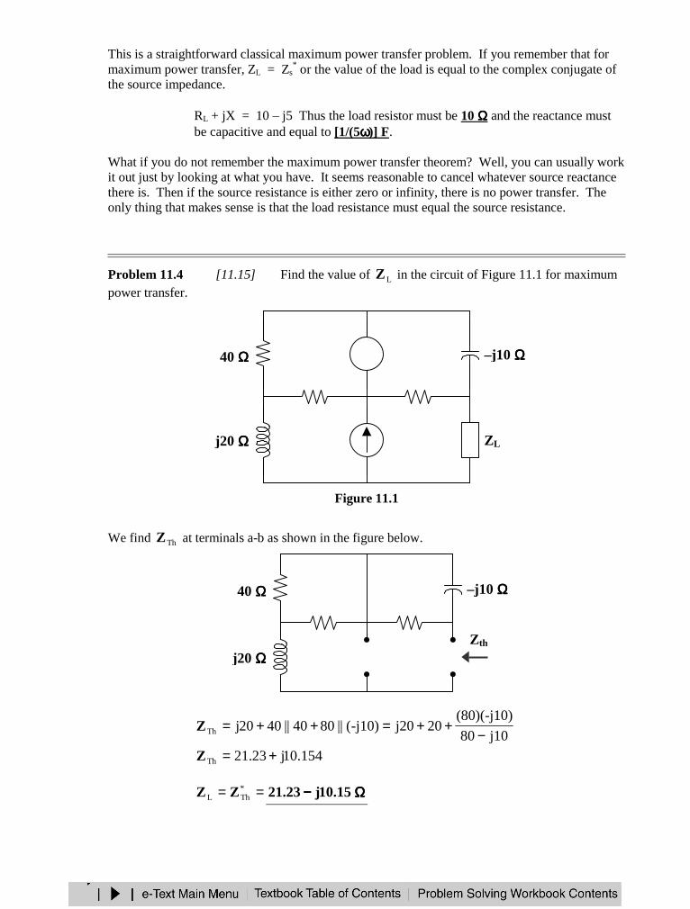
This is a straightforward classical maximum power transfer problem. If you remember that formaximum power transfer, ZL = Zs
* or the value of the load is equal to the complex conjugate ofthe source impedance.
RL + jX = 10 – j5 Thus the load resistor must be 10 ΩΩΩΩ and the reactance mustbe capacitive and equal to [1/(5ωωωω)] F.
What if you do not remember the maximum power transfer theorem? Well, you can usually workit out just by looking at what you have. It seems reasonable to cancel whatever source reactancethere is. Then if the source resistance is either zero or infinity, there is no power transfer. Theonly thing that makes sense is that the load resistance must equal the source resistance.
Problem 11.4 [11.15] Find the value of LZ in the circuit of Figure 11.1 for maximumpower transfer.
Figure 11.1
We find ThZ at terminals a-b as shown in the figure below.
j1080
(80)(-j10)20j20-j10)(||8040||4020jTh −
++=++=Z
154.10j23.21Th +=Z
== *ThL ZZ ΩΩΩΩ−−−− 15.10j23.21
40 ΩΩΩΩ –j10 ΩΩΩΩ80 ΩΩΩΩ40 ΩΩΩΩ
j20 ΩΩΩΩZth
40 ΩΩΩΩ –j10 ΩΩΩΩ80 ΩΩΩΩ
j20 ΩΩΩΩ
−+
ZL5∠∠∠∠ 0°°°° A
60∠∠∠∠ 0°°°° V
40 ΩΩΩΩ
EFFECTIVE OR RMS VALUE
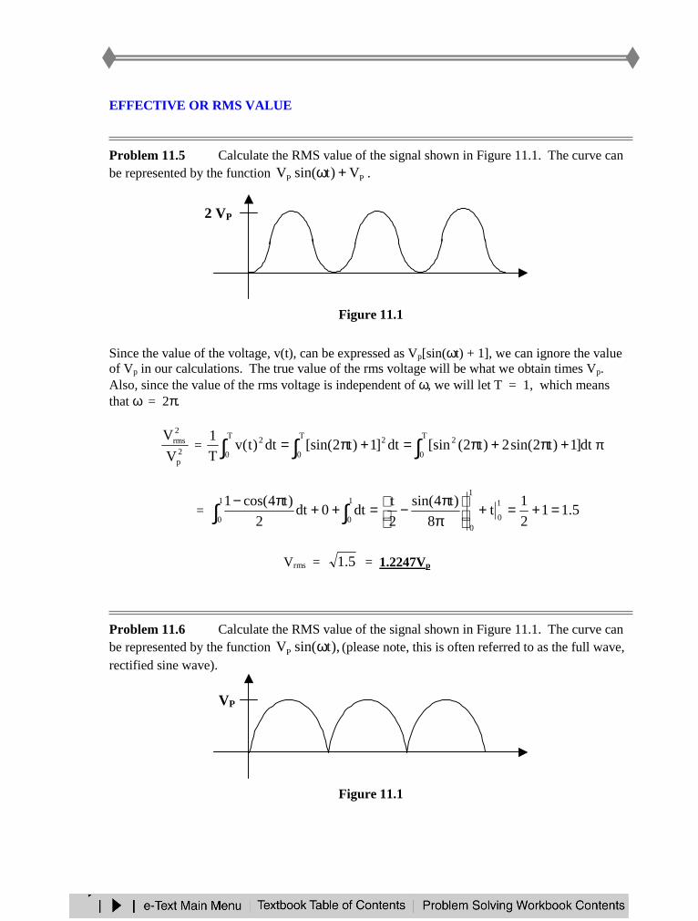
Problem 11.5 Calculate the RMS value of the signal shown in Figure 11.1. The curve canbe represented by the function PP V)tsin(V +ω .
Figure 11.1
Since the value of the voltage, v(t), can be expressed as Vp[sin(ωt) + 1], we can ignore the valueof Vp in our calculations. The true value of the rms voltage will be what we obtain times Vp.Also, since the value of the rms voltage is independent of ω, we will let T = 1, which meansthat ω = 2π.
2p
2rms
V
V = ∫∫∫ +π+π=+π=
T
0
22T
0
T
0
2 dt]1)t2sin(2)t2([sindt]1)t2[sin(dt)t(vT
1π
= 5.112
1t
8
)t4sin(
2
tdt0dt
2
)t4cos(1 1
0
1
0
1
0
1
0=+=+
ππ−=++π−
∫∫
Vrms = 5.1 = 1.2247Vp
Problem 11.6 Calculate the RMS value of the signal shown in Figure 11.1. The curve canbe represented by the function ),tsin(VP ω (please note, this is often referred to as the full wave,rectified sine wave).
Figure 11.1
2 VP
VP
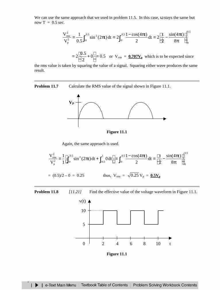
We can use the same approach that we used in problem 11.5. In this case, ω stays the same butnow T = 0.5 sec.
5.0
0
5.0
0
5.0
0
2
2p
2rms
8
)t4sin(
2
t2dt
2
)t4cos(12dt)t2(sin
5.0
1
V
V
ππ−=π−=π= ∫∫
5.002
5.02 =
+= or Vrms = 0.707Vp which is to be expected since
the rms value is taken by squaring the value of a signal. Squaring either wave produces the sameresult.
Problem 11.7 Calculate the RMS value of the signal shown in Figure 11.1.
Figure 11.1
Again, the same approach is used.
5.0
0
5.0
0
5.0
0
1
5.0
22p
2rms
8
)t4sin(
2
tdt
2
)t4cos(1dt0dt)t2(sin
1
1
V
V
ππ−=π−=
+π= ∫∫ ∫
= (0.5)/2 – 0 = 0.25 thus, Vrms = 25.0 Vp = 0.5Vp
Problem 11.8 [11.21] Find the effective value of the voltage waveform in Figure 11.1.
Figure 11.1
4
v(t)
10
t
5
2 6 1080
VP

4T = ,
<<<<
=4t210
2t05)t(v
[ ] 5.62]20050[4
1dt)10(dt5
4
1V
4
2
22
0
22rms =+=+= ∫∫
=rmsV V906.7
APPARENT POWER AND POWER FACTOR
Problem 11.9 Given the circuit in Figure 11.1, °∠= 30100Vin and °∠= 6010I ,
(a) calculate the average power assuming that inV and I are already rms values(b) calculate the apparent power(c) calculate the reactive power
Figure 11.1
(a) power = 100x10cos(30°– 60°) = 1000cos(-30°) = 866 watts
(b) apparent power = 100x10 = 1000 = 1 kVA
(c) reactive power = 100x10sin(30°– 60°) = 1000sin(-30°) = –500 VARS
Problem 11.10 [11.29] A relay coil is connected to a 210-V, 50-Hz supply. If it has aresistance of 30 Ω and an inductance of 0.5 H, calculate the apparent power and the power factor.
08.157j)5.0)(50)(2(jLjH5.0 =π=ω→
08.157j30jXR L +=+=Z
+− Z
I
Vin
08.157j30
)210( 2
*
2
−==
Z
VS
Apparent power ===160
)210( 2
S 275.6 VA
)19.79cos(36
08.157tancoscospf 1- °=
=θ=
=pf (lagging)1876.0
COMPLEX POWER
Problem 11.11 [11.35] Determine the complex power for the following cases:(a) W269P = , VAR150Q = (capacitive)
(b) VAR2000Q = , 9.0pf = (leading)
(c) VA600S = , VAR450Q = (inductive)
(d) V220Vrms = , kW1P = , Ω= 40Z (inductive)
(a) =−= jQPS VA150j269 −−−−
(b) °=θ→=θ= 84.259.0cospf
31.4588)84.25sin(
2000
sin
QSsinSQ =
°=
θ=→θ=
48.4129cosSP =θ=
=S VA2000j4129 −−−−
(c) 75.0600
450
S
QsinsinSQ ===θ→θ=
59.48=θ , 6614.0pf =
86.396)06614)(600(cosSP ==θ=
=S VA450j9.396 ++++
(d) 121040
)220(S
22
===Z
V
8264.01210
1000
S
PcoscosSP ===θ→θ=
°=θ 26.34
25.681sinSQ =θ=
=S VA2.681j1000 ++++
CONSERVATION OF AC POWER
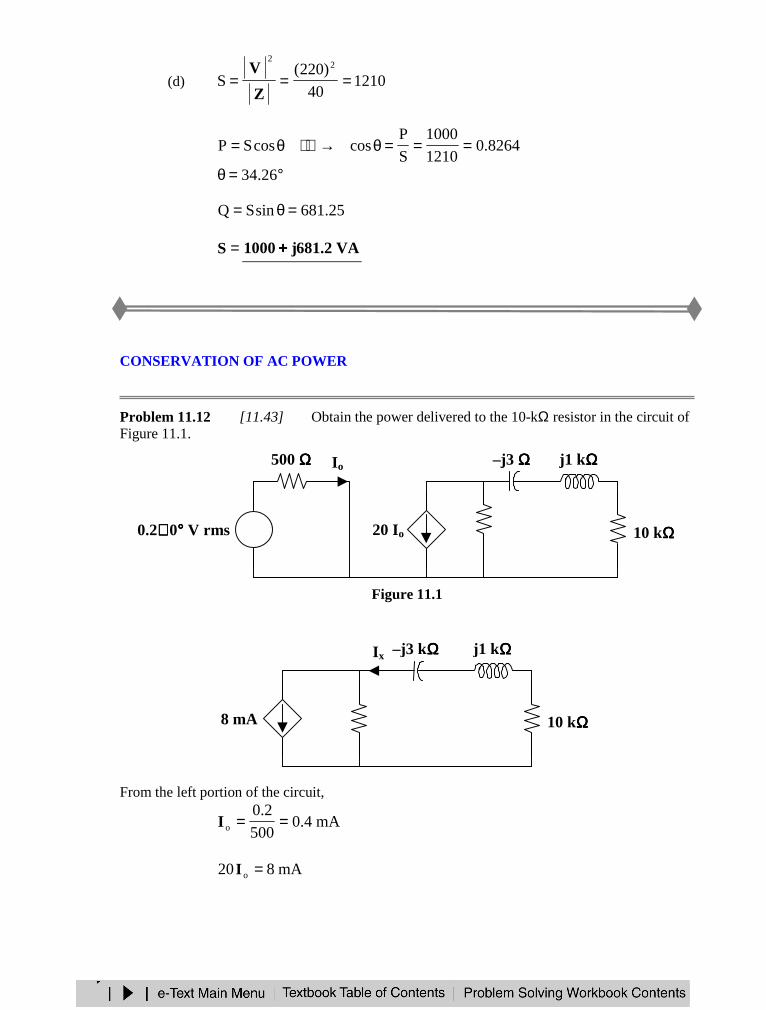
Problem 11.12 [11.43] Obtain the power delivered to the 10-kΩ resistor in the circuit ofFigure 11.1.
Figure 11.1
From the left portion of the circuit,
mA4.0500
2.0o ==I
mA820 o =I
j1 kΩΩΩΩ
10 kΩΩΩΩ
–j3 kΩΩΩΩ
8 mA
Ix
4 kΩΩΩΩ
j1 kΩΩΩΩ
10 kΩΩΩΩ
–j3 ΩΩΩΩ
20 Io4 kΩΩΩΩ
500 ΩΩΩΩ
+−
Io
0.2∠∠∠ ∠ 0°°°° V rms
From the right portion of the circuit,
mAj7
16)mA8(
3jj104
4x −
=−++
=I
)1010(50
)1016(RIP 3
2-32
x ××××⋅⋅⋅⋅××××========
====P mW2.51
POWER FACTOR CORRECTION
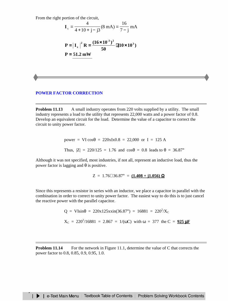
Problem 11.13 A small industry operates from 220 volts supplied by a utility. The smallindustry represents a load to the utility that represents 22,000 watts and a power factor of 0.8.Develop an equivalent circuit for the load. Determine the value of a capacitor to correct thecircuit to unity power factor.
power = VI cosθ = 220xIx0.8 = 22,000 or I = 125 A
Thus, |Z| = 220/125 = 1.76 and cosθ = 0.8 leads to θ = 36.87°
Although it was not specified, most industries, if not all, represent an inductive load, thus thepower factor is lagging and θ is positive.
Z = 1.76∠ 36.87° = (1.408 + j1.056) ΩΩΩΩ
Since this represents a resistor in series with an inductor, we place a capacitor in parallel with thecombination in order to correct to unity power factor. The easiest way to do this is to just cancelthe reactive power with the parallel capacitor.
Q = VIsinθ = 220x125xxin(36.87°) = 16881 = 2202/XC
XC = 2202/16881 = 2.867 = 1/(ωC) with ω = 377 the C = 925 µµµµF
Problem 11.14 For the network in Figure 11.1, determine the value of C that corrects thepower factor to 0.8, 0.85, 0.9, 0.95, 1.0.
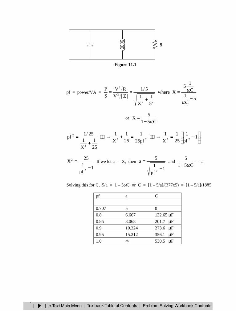
Figure 11.1
pf = power/VA =
5C
1C
15
Xwhere
5
1
X
1
5/1
|Z|V
RV
S
P
22
2
2
−ω
ω=+
==
or C51
5X
ω−=
−=→=+→
+= 1
pf
1
25
1
X
1
pf25
1
25
1
X
1
25
1
X
125/1
pf2222
2
2
1pf
125
X
2
2
−= If we let a = X, then
1pf
1
5a
2−
= and C51
5
ω− = a
Solving this for C, 5/a = 1 – 5ωC or C = [1 – 5/a]/(377x5) = [1 – 5/a]/1885
pf a C
0.707 5 0
0.8 6.667 132.65 µF
0.85 8.068 201.7 µF
0.9 10.324 273.6 µF
0.95 15.212 356.1 µF
1.0 ∞ 530.5 µF
5j5C
Problem 11.15 Referring to the results of Problem 11.14, what can you say about the relativecosts of power factor correction?
To correct to 0.8 pf requires a 132.65 µF capacitor. (Clearly one would purchase the closest valuecommercially available for the desired use. Taking into account energy requirements, this mightbe a 150 µF capacitor.)
To correct to 0.85 requires only a 200 µF capacitor. However, to go to 0.95 requires almost twoof these. This would mean that the cost of correcting to 0.95 is twice as much as correcting to0.85. To go to unity costs even more. It would require 4 times the number of capacitors tocorrect to unity as to correct to 0.8. Fortunately, utilities gain little from corrections from 0.85 tounity, which can save a lot since these compensating capacitors are very expensive.
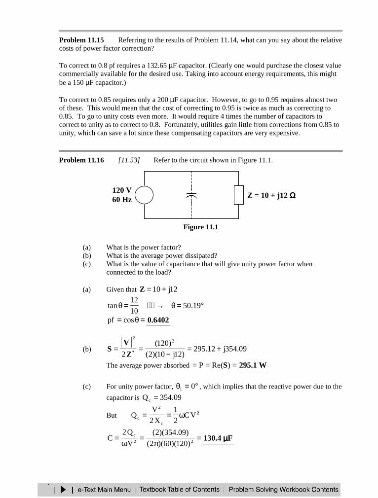
Problem 11.16 [11.53] Refer to the circuit shown in Figure 11.1.
Figure 11.1
(a) What is the power factor?(b) What is the average power dissipated?(c) What is the value of capacitance that will give unity power factor when
connected to the load?
(a) Given that 12j10+=Z
°=θ→=θ 19.5010
12tan
=θ= cospf 6402.0
(b) 09.354j12.295)12j10)(2(
)120(
2
2
*
2
+=−
==Z
VS
The average power absorbed === )Re(P S W1.295
(c) For unity power factor, °=θ 01 , which implies that the reactive power due to the
capacitor is 09.354Qc =
But 2VC2
1
X2
VQ
c
2
c ω==
=π
=ω
= 22c
)120)(60)(2(
)09.354)(2(
V
Q2C F4.130 µµµµ
+−
Z = 10 + j12 ΩΩΩΩ120 V60 Hz C
APPLICATIONS
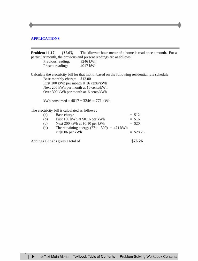
Problem 11.17 [11.63] The kilowatt-hour-meter of a home is read once a month. For aparticular month, the previous and present readings are as follows:
Previous reading: 3246 kWhPresent reading: 4017 kWh
Calculate the electricity bill for that month based on the following residential rate schedule:Base monthly charge: $12.00First 100 kWh per month at 16 cents/kWhNext 200 kWh per month at 10 cents/kWhOver 300 kWh per month at 6 cents/kWh
kWh consumed kWh77132464017 =−=
The electricity bill is calculated as follows :(a) Base charge = $12(b) First 100 kWh at $0.16 per kWh = $16(c) Next 200 kWh at $0.10 per kWh = $20(d) The remaining energy (771 – 300) = 471 kWh
at $0.06 per kWh = $28.26.
Adding (a) to (d) gives a total of 26.76$
CHAPTER 12 - THREE-PHASE CIRCUITS
List of topics for this chapter :Balanced Three-Phase VoltagesBalanced Wye-Wye ConnectionBalanced Wye-Delta ConnectionBalanced Delta-Delta ConnectionBalanced Delta-Wye ConnectionPower in a Balanced SystemUnbalanced Three-Phase SystemsPSpice for Three-Phase CircuitsApplications
BALANCED THREE-PHASE VOLTAGES
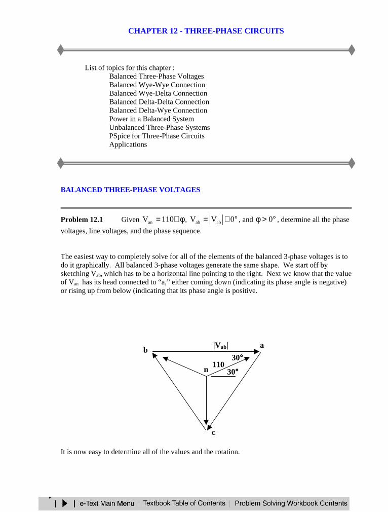
Problem 12.1 Given φ∠= 110Van , °∠= 0VV abab , and °>φ 0 , determine all the phase
voltages, line voltages, and the phase sequence.
The easiest way to completely solve for all of the elements of the balanced 3-phase voltages is todo it graphically. All balanced 3-phase voltages generate the same shape. We start off bysketching Vab, which has to be a horizontal line pointing to the right. Next we know that the valueof Van has its head connected to “a,” either coming down (indicating its phase angle is negative)or rising up from below (indicating that its phase angle is positive.
It is now easy to determine all of the values and the rotation.
ab
c
n110
30°°°°|Vab|
30°°°°
Clearly the rotation is acb, or a negative phase sequence.
Because this is a triangle with equal sides, the interior angles are 60° and the line-to-neutralvoltages bisect the angle. Thus Van has to be at 30°. This then leads to the following;
Van = 110∠∠∠∠ 30°°°° V, Vbn = 110∠∠∠∠ 150°°°° V, Vcn = 110∠∠∠∠ –90°°°° Vand
|Vab| = 110 3 = 190.52therefore
Vab = 190.52∠∠∠∠ 0°°°° V, Vbc = 190.52∠∠∠∠ 120°°°° V, Vca = 190.52∠∠∠∠ –120°°°° V
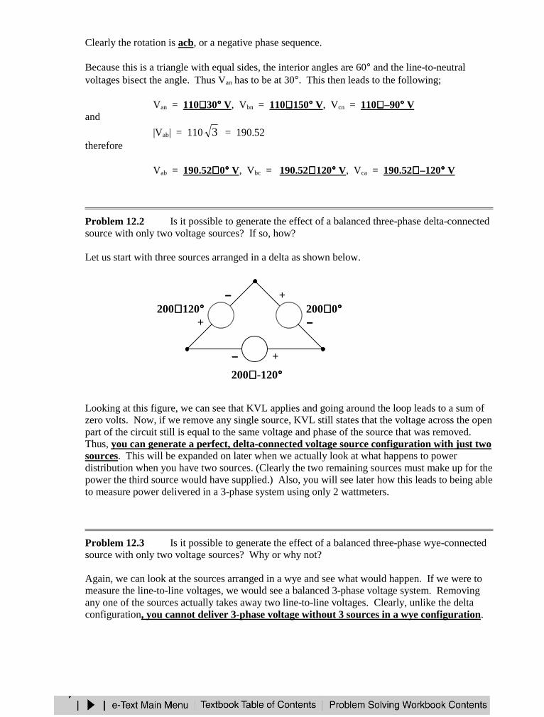
Problem 12.2 Is it possible to generate the effect of a balanced three-phase delta-connectedsource with only two voltage sources? If so, how?
Let us start with three sources arranged in a delta as shown below.
Looking at this figure, we can see that KVL applies and going around the loop leads to a sum ofzero volts. Now, if we remove any single source, KVL still states that the voltage across the openpart of the circuit still is equal to the same voltage and phase of the source that was removed.Thus, you can generate a perfect, delta-connected voltage source configuration with just twosources. This will be expanded on later when we actually look at what happens to powerdistribution when you have two sources. (Clearly the two remaining sources must make up for thepower the third source would have supplied.) Also, you will see later how this leads to being ableto measure power delivered in a 3-phase system using only 2 wattmeters.
Problem 12.3 Is it possible to generate the effect of a balanced three-phase wye-connectedsource with only two voltage sources? Why or why not?
Again, we can look at the sources arranged in a wye and see what would happen. If we were tomeasure the line-to-line voltages, we would see a balanced 3-phase voltage system. Removingany one of the sources actually takes away two line-to-line voltages. Clearly, unlike the deltaconfiguration, you cannot deliver 3-phase voltage without 3 sources in a wye configuration.
−−−−
+200∠∠∠∠ 0°°°°200∠∠∠∠ 120°°°°
200∠∠∠∠ -120°°°°
−−−−
+
−−−− +

BALANCED WYE-WYE CONNECTION
Problem 12.4 [12.7] Obtain the line currents in the three-phase circuit of Figure 12.1.
Figure 12.1
This is a balanced Y-Y system.
440∠∠∠ ∠ 0°°°° V +− ZY = 6 −−−− j8 ΩΩΩΩ
Ia
6 – j8 ΩΩΩΩ
A
N
6 – j8 ΩΩΩΩ 6 – j8 ΩΩΩΩ
Ic
Ib
−−−−+
+−
440∠∠∠ ∠ –120°°°°440∠∠∠ ∠ 120°°°°+
−−−−
440∠∠∠ ∠ 0°°°°
a
n
−−−−
+200∠∠∠ ∠ 120°°°° 200∠∠∠ ∠ 0°°°°
−−−−
+
200∠∠∠ ∠ -120°°°°
−−−−
+
Using the per-phase circuit shown above,
=−
°∠=
8j6
0440aI A53.1344 °°°°∠∠∠ ∠
=°∠= 120-ab II A66.87-44 °°°°∠∠∠ ∠=°∠= 120ac II A13.73144 °°°°∠∠∠ ∠
BALANCED WYE-DELTA CONNECTION
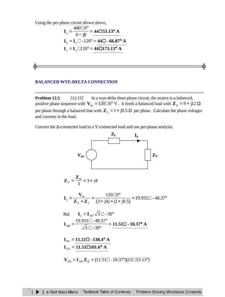
Problem 12.5 [12.15] In a wye-delta three-phase circuit, the source is a balanced,positive phase sequence with V0120an °∠=V . It feeds a balanced load with Ω+=∆ 12j9Z
per phase through a balanced line with Ω+= 5.0j1LZ per phase. Calculate the phase voltagesand currents in the load.
Convert the ∆-connected load to a Y-connected load and use per-phase analysis.
4j33Y +== ∆Z
Z
°∠=+++°∠
=+
= 48.37-931.19)5.0j1()4j3(
0120
LY
ana ZZ
VI
But °∠= 30-3ABa II
=°∠
°∠=
30-3
48.37-931.19ABI A18.37-51.11 °°°°∠∠∠ ∠
=BCI A138.4-51.11 °°°°∠∠∠ ∠=CAI A101.651.11 °°°°∠∠∠ ∠
)53.1315)(18.37-51.11(ABAB °∠°∠== ∆ZIV
ZY
ZL
+−
Van
Ia
=ABV V76.436.172 °°°°∠∠∠ ∠=BCV V85.24-6.172 °°°°∠∠∠ ∠=CAV V8.5416.172 °°°°∠∠∠ ∠
BALANCED DELTA-DELTA CONNECTION
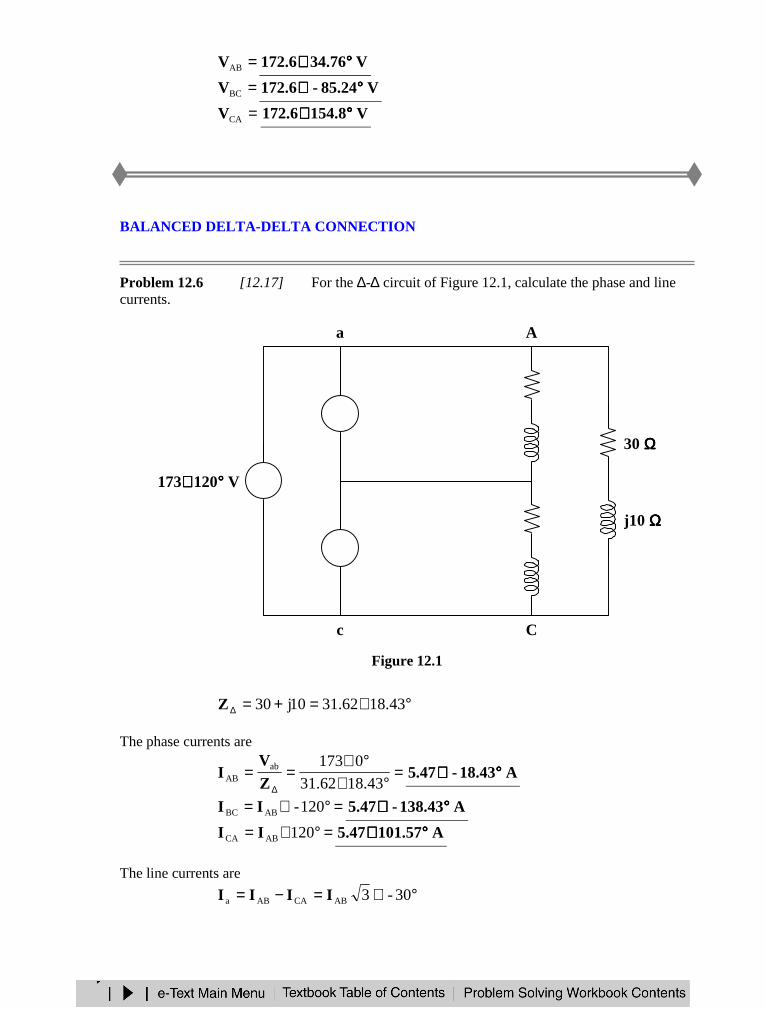
Problem 12.6 [12.17] For the ∆-∆ circuit of Figure 12.1, calculate the phase and linecurrents.
Figure 12.1
°∠=+=∆ 18.4362.3110j30Z
The phase currents are
=°∠
°∠==
∆ 18.4362.31
0173abAB Z
VI A18.43-47.5 °°°°∠∠∠ ∠
=°∠= 120-ABBC II A138.43-47.5 °°°°∠∠∠ ∠=°∠= 120ABCA II A101.5747.5 °°°°∠∠∠ ∠
The line currents are
°∠=−= 30-3ABCAABa IIII
a
c
A
B
C
30 ΩΩΩΩ
30 ΩΩΩΩ
j10 ΩΩΩΩ+−
173∠∠∠ ∠ 120°°°° V
173∠∠∠ ∠ 0°°°° V+−
j10 ΩΩΩΩ
+−
173∠∠∠ ∠ –120°°°° V
30 ΩΩΩΩ
j10 ΩΩΩΩ
b
=°∠= 48.43-347.5aI A48.43-474.9 °°°°∠∠∠ ∠
=°∠= 120-ab II A168.43-474.9 °°°°∠∠∠ ∠=°∠= 120ac II A71.57474.9 °°°°∠∠∠ ∠
BALANCED DELTA-WYE CONNECTION
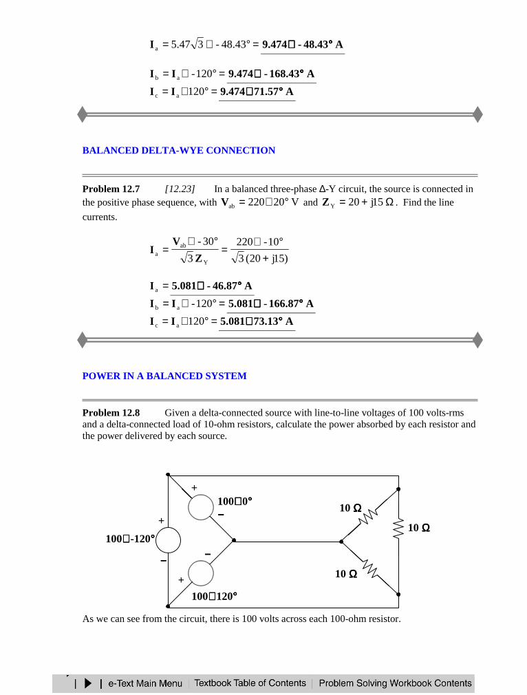
Problem 12.7 [12.23] In a balanced three-phase ∆-Y circuit, the source is connected inthe positive phase sequence, with V20220ab °∠=V and Ω+= 15j20YZ . Find the line
currents.
)15j20(3
10-220
3
30-
Y
aba +
°∠=
°∠=
Z
VI
=aI A46.87-081.5 °°°°∠∠∠ ∠=°∠= 120-ab II A166.87-081.5 °°°°∠∠∠ ∠
=°∠= 120ac II A73.13081.5 °°°°∠∠∠ ∠
POWER IN A BALANCED SYSTEM
Problem 12.8 Given a delta-connected source with line-to-line voltages of 100 volts-rmsand a delta-connected load of 10-ohm resistors, calculate the power absorbed by each resistor andthe power delivered by each source.
As we can see from the circuit, there is 100 volts across each 100-ohm resistor.
−−−−
+
100∠∠∠ ∠ 120°°°°
100∠∠∠ ∠ 0°°°°−−−−
+
100∠∠∠ ∠ -120°°°°
−−−−
+10 ΩΩΩΩ
10 ΩΩΩΩ
10 ΩΩΩΩ
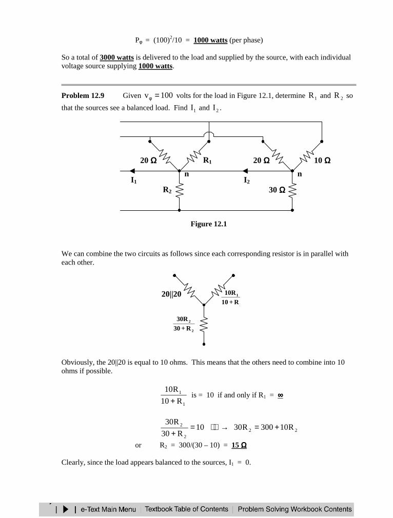
Pφ = (100)2/10 = 1000 watts (per phase)
So a total of 3000 watts is delivered to the load and supplied by the source, with each individualvoltage source supplying 1000 watts.
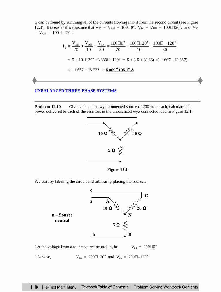
Problem 12.9 Given 100v =φ volts for the load in Figure 12.1, determine 1R and 2R so
that the sources see a balanced load. Find 1I and 2I .
Figure 12.1
We can combine the two circuits as follows since each corresponding resistor is in parallel witheach other.
Obviously, the 20||20 is equal to 10 ohms. This means that the others need to combine into 10ohms if possible.
1
1
R10
R10
+ is = 10 if and only if R1 = ∞∞∞∞
222
2 R10300R3010R30
R30+=→=
+or R2 = 300/(30 – 10) = 15 ΩΩΩΩ
Clearly, since the load appears balanced to the sources, I1 = 0.
20 ΩΩΩΩ R1
R2
n
20 ΩΩΩΩ 10 ΩΩΩΩ
30 ΩΩΩΩ
nI2I1
20||201
1
R10R10
+
2
2
R30R30
+
I2 can be found by summing all of the currents flowing into it from the second circuit (see Figure12.3). It is easier if we assume that V20 = VAN = 100∠ 0°, V10 = VBN = 100∠ 120°, and V30
= VCN = 100∠ –120°.
30
120100
10
120100
20
0100
30
V
10
V
20
VI CNBNAN
2
°−∠+°∠+°∠=++=
= 5 + 10∠ 120° +3.333∠ –120° = 5 + (–5 + J8.66) +(–1.667 – J2.887)
= –1.667 + J5.773 = 6.009∠∠∠ ∠ 106.1°°°° A
UNBALANCED THREE-PHASE SYSTEMS
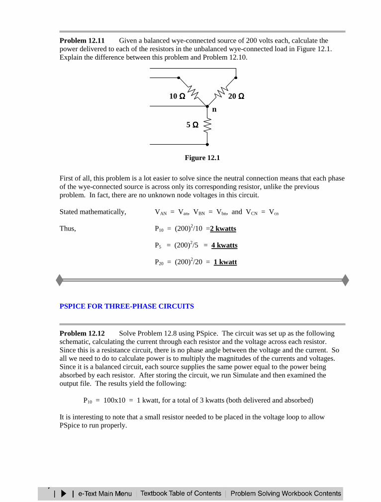
Problem 12.10 Given a balanced wye-connected source of 200 volts each, calculate thepower delivered to each of the resistors in the unbalanced wye-connected load in Figure 12.1.
Figure 12.1
We start by labeling the circuit and arbitrarily placing the sources.
Let the voltage from a to the source neutral, n, be Van = 200∠ 0°
Likewise, Vbn = 200∠ 120° and Vcn = 200∠ –120°
10 ΩΩΩΩ 20 ΩΩΩΩ
5 ΩΩΩΩ
10 ΩΩΩΩ 20 ΩΩΩΩ
5 ΩΩΩΩ
n – Sourceneutral
c
b
a
N
C
B
A

This can easily be solved if we look at it as a simple circuits problem with only one unknownnode voltage, VN (measured with respect to n).
We now can write a nodal equation at node N.
020
VV
5
VV
10
VV cnNbnNanN =−
+−
+−
Solving for VN we get,
°−∠+°∠+= 1207
200120
7
800
7
400VN
= 57.14 + (–14.285 – j24.74) + (–57.14 + j98.98)
= –14.28 + j74.24 = 75.6∠ 100.9°
Now that we have VN, we can either find the currents through the resistors or voltages acrossthem and then calculate the power. Solving for the voltages we get,
VAN = Van – VN = 200 – (–14.28 + j74.24) = 214.28 – j74.24 = 226.8∠ –19.11°
VBN = Vbn – VN = –100 + j173.21 – (–14.28 + j74.24) = –85.72 + j98.97
= 130.93∠ 130.9°
VCN = Vcn – VN = –100 – j173.21 – (–14.28 + j74.24) = –85.72 – j247.45
= 261.88∠ –109.11°
Now to calculate the power.
===10
)8.226(
10
VP
22
AN10 5.144 kwatts
===5
)93.130(
5
VP
22
BN5 3.429 kwatts
===20
)88.261(
20
VP
22
CN20 3.429 kwatts
Problem 12.11 Given a balanced wye-connected source of 200 volts each, calculate thepower delivered to each of the resistors in the unbalanced wye-connected load in Figure 12.1.Explain the difference between this problem and Problem 12.10.
Figure 12.1
First of all, this problem is a lot easier to solve since the neutral connection means that each phaseof the wye-connected source is across only its corresponding resistor, unlike the previousproblem. In fact, there are no unknown node voltages in this circuit.
Stated mathematically, VAN = Van, VBN = Vbn, and VCN = Vcn
Thus, P10 = (200)2/10 =2 kwatts
P5 = (200)2/5 = 4 kwatts
P20 = (200)2/20 = 1 kwatt
PSPICE FOR THREE-PHASE CIRCUITS
Problem 12.12 Solve Problem 12.8 using PSpice. The circuit was set up as the followingschematic, calculating the current through each resistor and the voltage across each resistor.Since this is a resistance circuit, there is no phase angle between the voltage and the current. Soall we need to do to calculate power is to multiply the magnitudes of the currents and voltages.Since it is a balanced circuit, each source supplies the same power equal to the power beingabsorbed by each resistor. After storing the circuit, we run Simulate and then examined theoutput file. The results yield the following:
P10 = 100x10 = 1 kwatt, for a total of 3 kwatts (both delivered and absorbed)
It is interesting to note that a small resistor needed to be placed in the voltage loop to allowPSpice to run properly.
10 ΩΩΩΩ 20 ΩΩΩΩ
5 ΩΩΩΩ
n
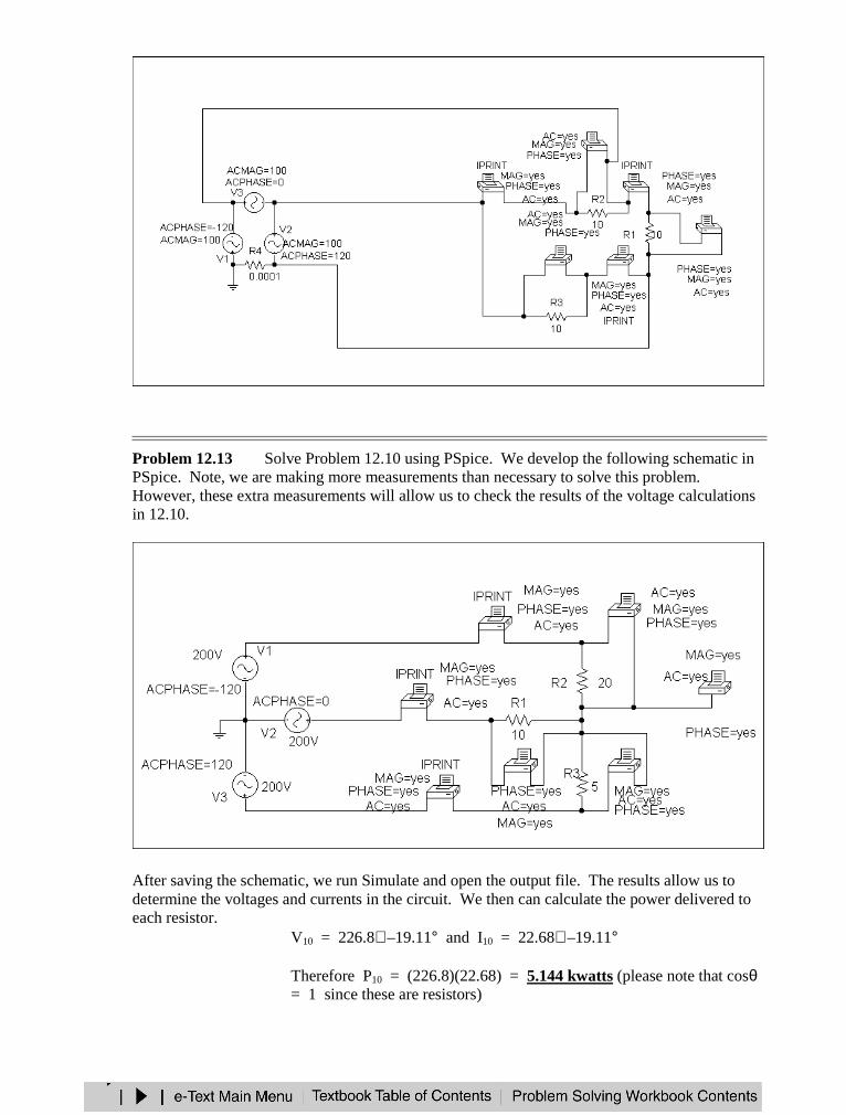
Problem 12.13 Solve Problem 12.10 using PSpice. We develop the following schematic inPSpice. Note, we are making more measurements than necessary to solve this problem.However, these extra measurements will allow us to check the results of the voltage calculationsin 12.10.
After saving the schematic, we run Simulate and open the output file. The results allow us todetermine the voltages and currents in the circuit. We then can calculate the power delivered toeach resistor.
V10 = 226.8∠ –19.11° and I10 = 22.68∠ –19.11°
Therefore P10 = (226.8)(22.68) = 5.144 kwatts (please note that cosθ= 1 since these are resistors)

V5 = 130.9∠ 130.9° and I5 = 26.19∠ 130.9°
Therefore P20 = (130.9)(26.19) = 3.428 kwatts
V20 = 261.9∠ –109.1° and I20 = 13.09∠ –109.1°
Therefore P20 = (261.9)(13.09) = 3.428 kwattsGoing back to the solution obtained by hand, we see that we have virtually the same values ofbranch voltages. PSpice also gave us the value of VNn = 79.59∠ 100.9°, which agrees. Thisshows the value of using PSpice to check results obtained by hand.
Problem 12.14 [12.49] Given the circuit in Figure 12.1, use PSpice to determinecurrents aAI and voltage BNV .
Figure 12.1
The schematic is shown below.
A
C
a j3 ΩΩΩΩ4 ΩΩΩΩ240∠∠∠∠ 0°°°° V
− +
b j3 ΩΩΩΩ4 ΩΩΩΩ240∠∠∠∠ –120°°°° V
− +
c j3 ΩΩΩΩ4 ΩΩΩΩ− +
240∠∠∠∠ 120°°°° V
–j36 ΩΩΩΩ
–j36 ΩΩΩΩ –j36 ΩΩΩΩ
n NB j15 ΩΩΩΩ10 ΩΩΩΩ
j15 ΩΩΩΩ10 ΩΩΩΩ
j15 ΩΩΩΩ10 ΩΩΩΩ
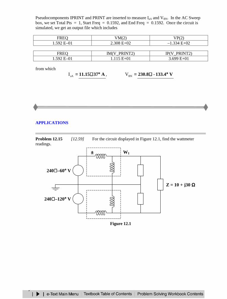
Pseudocomponents IPRINT and PRINT are inserted to measure IaA and VBN. In the AC Sweepbox, we set Total Pts = 1, Start Freq = 0.1592, and End Freq = 0.1592. Once the circuit issimulated, we get an output file which includes
FREQ VM(2) VP(2)1.592 E–01 2.308 E+02 –1.334 E+02
FREQ IM(V_PRINT2) IP(V_PRINT2)1.592 E–01 1.115 E+01 3.699 E+01
from which=aAI A3715.11 °°°°∠∠∠ ∠ , =BNV V4.133-8.230 °°°°∠∠∠ ∠
APPLICATIONS
Problem 12.15 [12.59] For the circuit displayed in Figure 12.1, find the wattmeterreadings.
Figure 12.1
240∠∠∠ ∠ –120°°°° V +−
240∠∠∠ ∠ –60°°°° V +−
Z
Z
Z = 10 + j30 ΩΩΩΩ
W1
W2
±±±±±±±±
±±±± ±±±±
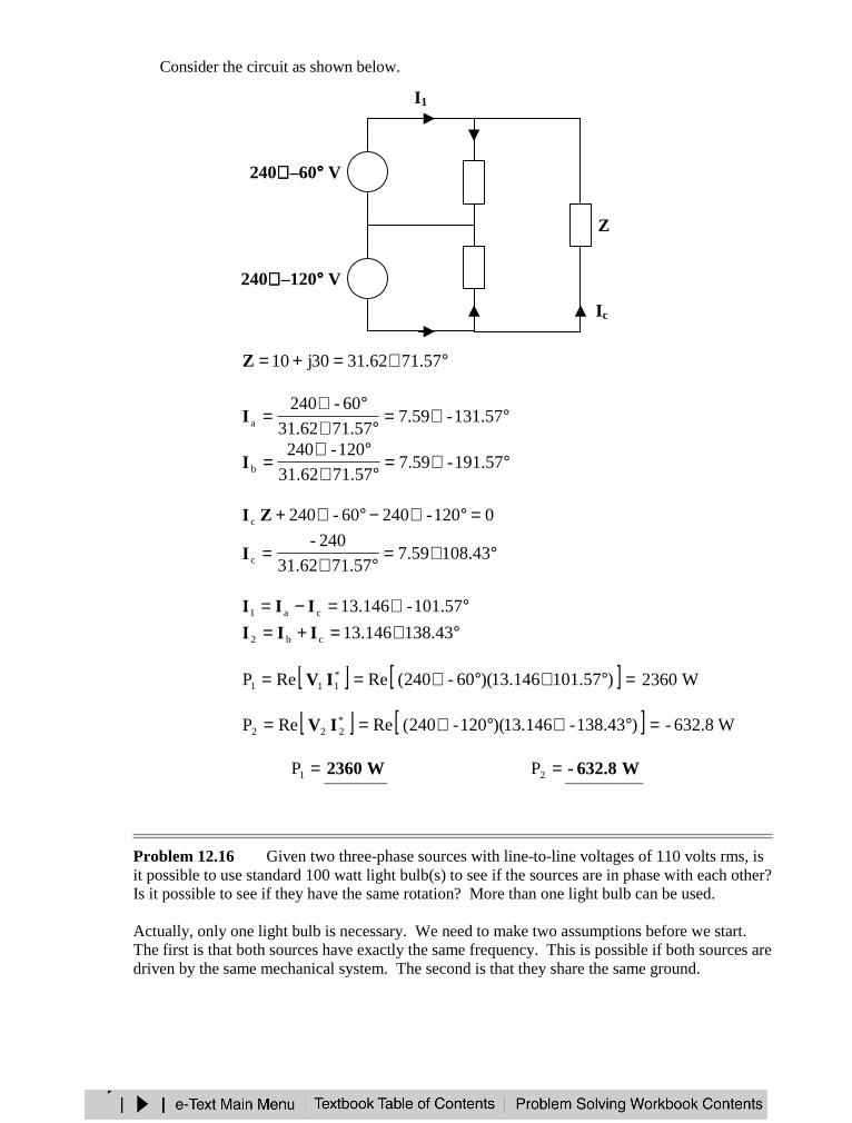
Consider the circuit as shown below.
°∠=+= 71.5762.3130j10Z
°∠=°∠
°∠= 131.57-59.7
71.5762.31
60-240aI
°∠=°∠
°∠= 191.57-59.7
71.5762.31
120-240bI
0120-24060-240c =°∠−°∠+ZI
°∠=°∠
= 108.4359.771.5731.62
240-cI
°∠=−= 101.57-146.13ca1 III
°∠=+= 138.43146.13cb2 III
[ ] [ ] =°∠°∠== ).57101146.13)(60-240(ReReP *111 IV W2360
[ ] [ ] =°∠°∠== )138.43-146.13)(120-240(ReReP *222 IV W8.632-
=1P W2360 =2P W8.632-
Problem 12.16 Given two three-phase sources with line-to-line voltages of 110 volts rms, isit possible to use standard 100 watt light bulb(s) to see if the sources are in phase with each other?Is it possible to see if they have the same rotation? More than one light bulb can be used.
Actually, only one light bulb is necessary. We need to make two assumptions before we start.The first is that both sources have exactly the same frequency. This is possible if both sources aredriven by the same mechanical system. The second is that they share the same ground.
240∠∠∠∠ –60°°°° V +−
Ib
Ia
I1
−+
240∠∠∠∠ –120°°°° V
Ic
Z
Z
Z
I2
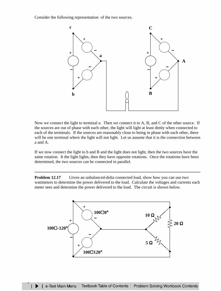
Consider the following representation of the two sources.
Now we connect the light to terminal a. Then we connect it to A, B, and C of the other source. Ifthe sources are out of phase with each other, the light will light at least dimly when connected toeach of the terminals. If the sources are reasonably close to being in phase with each other, therewill be one terminal where the light will not light. Let us assume that it is the connection betweena and A.
If we now connect the light to b and B and the light does not light, then the two sources have thesame rotation. It the light lights, then they have opposite rotations. Once the rotations have beendetermined, the two sources can be connected in parallel.
Problem 12.17 Given an unbalanced-delta connected load, show how you can use twowattmeters to determine the power delivered to the load. Calculate the voltages and currents eachmeter sees and determine the power delivered to the load. The circuit is shown below.
−−−−
+
100∠∠∠∠ 120°°°°
100∠∠∠∠ 0°°°°−−−−
+
100∠∠∠∠ -120°°°°
−−−−
+10 ΩΩΩΩ
5 ΩΩΩΩ
20 ΩΩΩΩ
−−−−
+
b
a−−−−
+
c
−−−−
+
−−−−
+
A
C
−−−−
+
B
−−−−
+
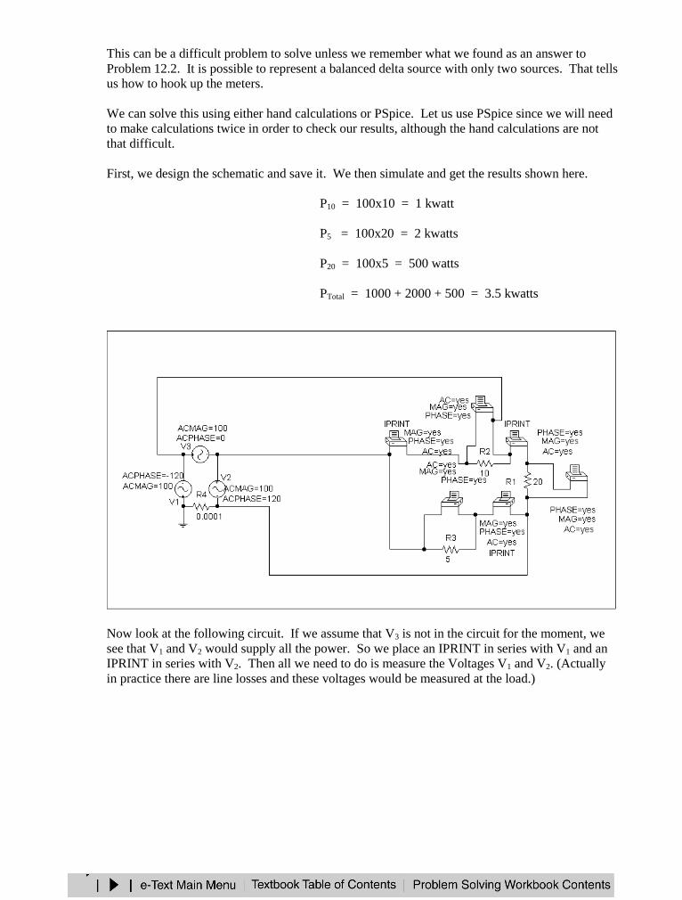
This can be a difficult problem to solve unless we remember what we found as an answer toProblem 12.2. It is possible to represent a balanced delta source with only two sources. That tellsus how to hook up the meters.
We can solve this using either hand calculations or PSpice. Let us use PSpice since we will needto make calculations twice in order to check our results, although the hand calculations are notthat difficult.
First, we design the schematic and save it. We then simulate and get the results shown here.
P10 = 100x10 = 1 kwatt
P5 = 100x20 = 2 kwatts
P20 = 100x5 = 500 watts
PTotal = 1000 + 2000 + 500 = 3.5 kwatts
Now look at the following circuit. If we assume that V3 is not in the circuit for the moment, wesee that V1 and V2 would supply all the power. So we place an IPRINT in series with V1 and anIPRINT in series with V2. Then all we need to do is measure the Voltages V1 and V2. (Actuallyin practice there are line losses and these voltages would be measured at the load.)
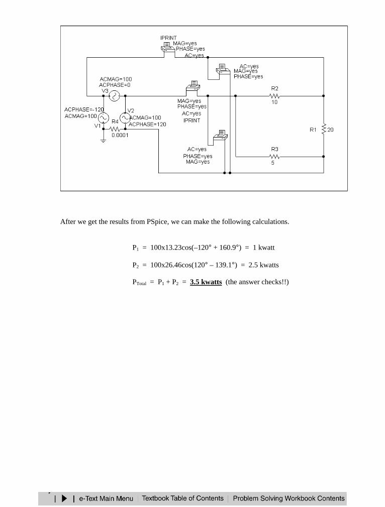
After we get the results from PSpice, we can make the following calculations.
P1 = 100x13.23cos(–120° + 160.9°) = 1 kwatt
P2 = 100x26.46cos(120° – 139.1°) = 2.5 kwatts
PTotal = P1 + P2 = 3.5 kwatts (the answer checks!!)
CHAPTER 13 - MAGNETICALLY COUPLED CIRCUITS
List of topics for this chapter :Mutual InductanceEnergy in a Coupled CircuitLinear TransformersIdeal TransformersThree-Phase TransformersPSpice Analysis of Magnetically Coupled CircuitsApplications
MUTUAL INDUCTANCE
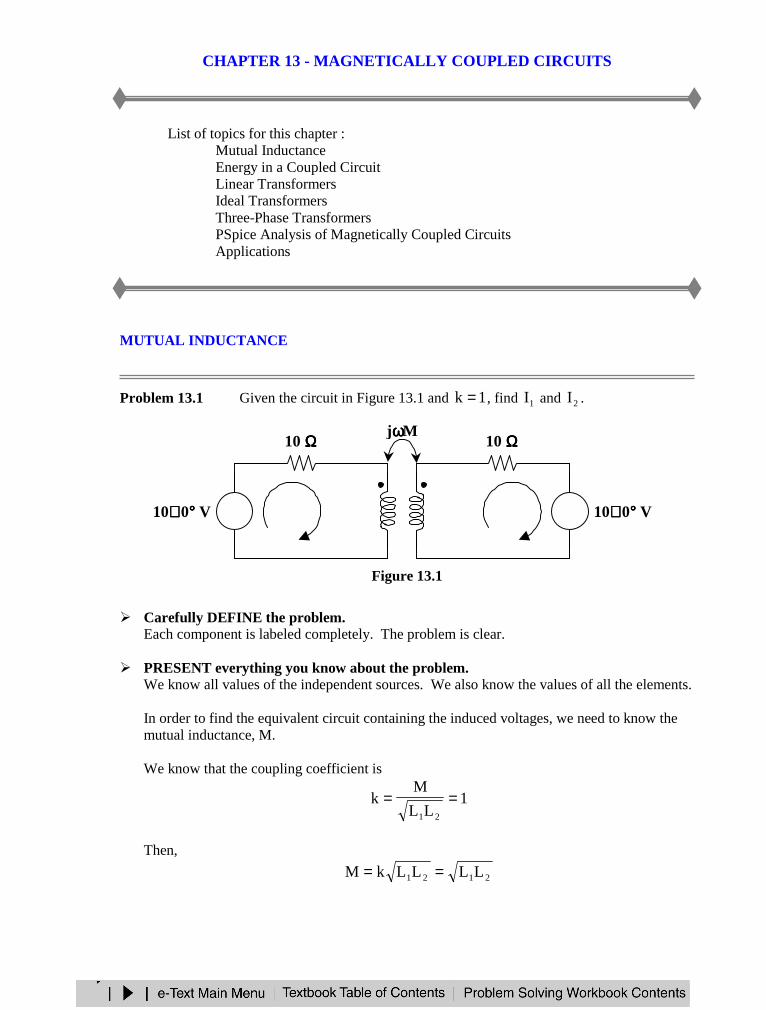
Problem 13.1 Given the circuit in Figure 13.1 and 1k = , find 1I and 2I .
Figure 13.1
Carefully DEFINE the problem.Each component is labeled completely. The problem is clear.
PRESENT everything you know about the problem.We know all values of the independent sources. We also know the values of all the elements.
In order to find the equivalent circuit containing the induced voltages, we need to know themutual inductance, M.
We know that the coupling coefficient is
1LL
Mk
21
==
Then,
2121 LLLLkM ==
10 ΩΩΩΩ10 ΩΩΩΩ
+−
10∠∠∠ ∠ 0°°°° V 10∠∠∠ ∠ 0°°°° V+−
I1 I2
jωωωωM
j10 ΩΩΩΩj10 ΩΩΩΩ
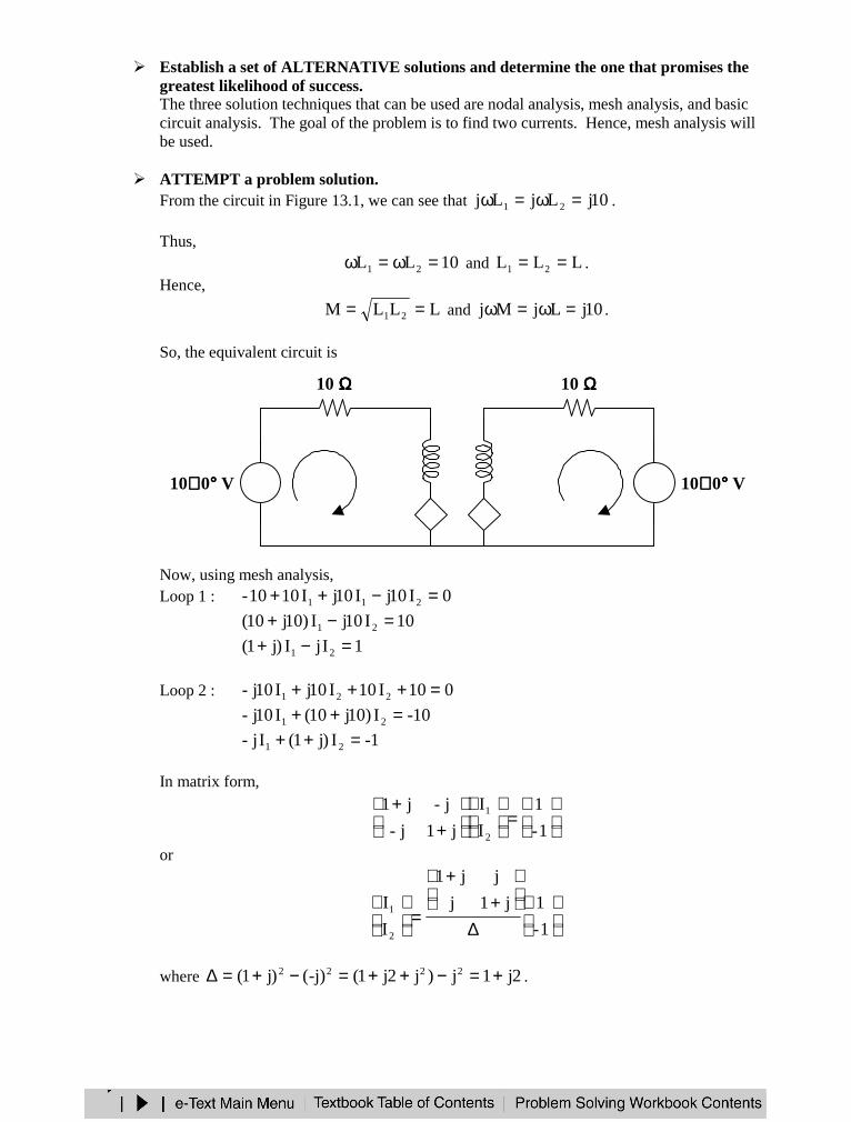
Establish a set of ALTERNATIVE solutions and determine the one that promises thegreatest likelihood of success.The three solution techniques that can be used are nodal analysis, mesh analysis, and basiccircuit analysis. The goal of the problem is to find two currents. Hence, mesh analysis willbe used.
ATTEMPT a problem solution.From the circuit in Figure 13.1, we can see that 10jLjLj 21 =ω=ω .
Thus,10LL 21 =ω=ω and LLL 21 == .
Hence,
LLLM 21 == and 10jLjMj =ω=ω .
So, the equivalent circuit is
Now, using mesh analysis,Loop 1 : 0I10jI10jI1010- 211 =−++
10I10jI)10j10( 21 =−+1IjI)j1( 21 =−+
Loop 2 : 010I10I10jI10j- 221 =+++10-I)10j10(I10j- 21 =++
1-I)j1(Ij- 21 =++
In matrix form,
=
++
1-
1
I
I
j1j-
j-j1
2
1
or
∆
++
=
1-
1j1j
jj1
I
I
2
1
where 2j1j)j2j1(-j)()j1( 2222 +=−++=−+=∆ .
10 ΩΩΩΩ10 ΩΩΩΩ
+−
10∠∠∠∠ 0°°°° V 10∠∠∠∠ 0°°°° V+−
I1 I2
j10 ΩΩΩΩj10 ΩΩΩΩ
−+
+− j10I1j10I2
Now,
++
+
+++
=
1-
1
2j1
j1
2j1
j2j1
j
2j1
j1
I
I
2
1
Therefore,
=°∠
°∠=
+=
+−+
=43.635
01
2j1
1
2j1
jj1I1 A43.63-4472.0 °∠
=°∠
°∠=
+=
++−
=43.635
1801
2j1
1-
2j1
)j1(jI2 A57.1164472.0 °∠
EVALUATE the solution and check for accuracy.Use KVL to check the solution.
The equation produced by KVL of the left loop is0I10jI10jI1010- 211 =−++
The equation produced by KVL of the right loop is0I10I10jI10j10 221 =++−
Inserting the values for 1I and 2I results in valid equations. Thus, our check for accuracywas successful.
Has the problem been solved SATISFACTORILY? If so, present the solution; if not,then return to “ALTERNATIVE solutions” and continue through the process again.This problem has been solved satisfactorily.
=1I A43.63-4472.0 °°°°∠∠∠∠ =2I A57.1164472.0 °°°°∠∠∠∠
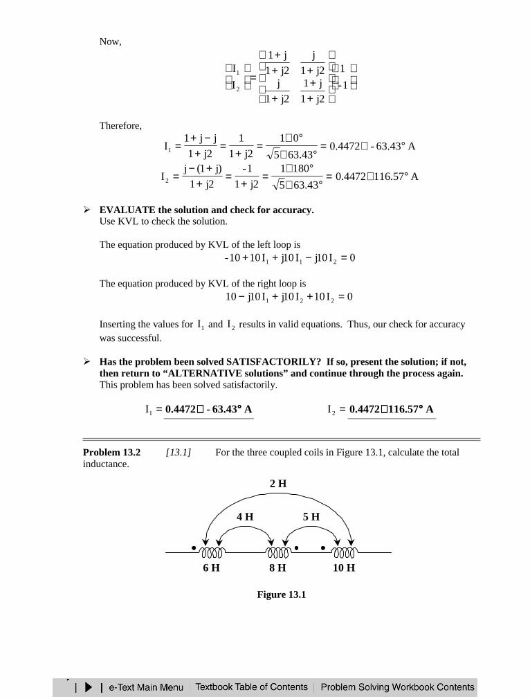
Problem 13.2 [13.1] For the three coupled coils in Figure 13.1, calculate the totalinductance.
Figure 13.1
8 H6 H 10 H
2 H
4 H 5 H
For coil 1, 4246MML 13121 =+−=+−For coil 2, 1-548MML 23212 =−−=−−For coil 3, 75210MML 32313 =−+=−+
=+−= 714LT H10
or 122312321T M2M2M2LLLL +−−++=)2)(2()5)(2()4)(2(1086LT +−−++=
=+−−++= 41081086LT H10
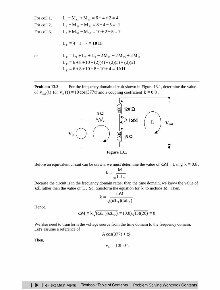
Problem 13.3 For the frequency domain circuit shown in Figure 13.1, determine the valueof )t(vout for )t377cos(10)t(vin = and a coupling coefficient 8.0k = .
Figure 13.1
Before an equivalent circuit can be drawn, we must determine the value of Mω . Using 8.0k = ,
21LL
Mk = .
Because the circuit is in the frequency domain rather than the time domain, we know the value ofLω rather than the value of L . So, transform the equation for k to include ω. Then,
)L)(L(
Mk
21 ωωω
= .
Hence,
8)20)(5()8.0()L)(L(kM 21 ==ωω=ω
We also need to transform the voltage source from the time domain to the frequency domain.Let's assume a reference of
)t377cos(A φ+ .Then,
°∠= 010Vin .
I2jωωωωM
5 ΩΩΩΩ
Vin+−
I1j5 ΩΩΩΩ
j20 ΩΩΩΩ+
Vout
−−−−
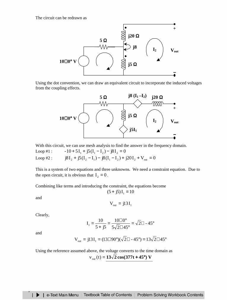
The circuit can be redrawn as
Using the dot convention, we can draw an equivalent circuit to incorporate the induced voltagesfrom the coupling effects.
With this circuit, we can use mesh analysis to find the answer in the frequency domain.Loop #1 : 0I8j)II(5jI510- 2211 =−−++Loop #2 : 0VI20j)II(8j)II(5jI8j out221122 =++−−−+
This is a system of two equations and three unknowns. We need a constraint equation. Due tothe open circuit, it is obvious that 0I2 = .
Combining like terms and introducing the constraint, the equations become10I)5j5( 1 =+
and
1out I13jV =
Clearly,
°∠=°∠
°∠=+
= 45-24525
010
5j5
10I1
and
°∠=°∠°∠== 45213)45-2)(9013(I13jV 1out
Using the reference assumed above, the voltage converts to the time domain as
=)t(vout V)45t377cos(213 °°°°++++
I2j8
5 ΩΩΩΩ
10∠∠∠∠ 0°°°° V +−
I1j5 ΩΩΩΩ
j20 ΩΩΩΩ+
Vout
−−−−
+
Vout
−−−−
I2
5 ΩΩΩΩ
10∠∠∠∠ 0°°°° V +−
I1j5 ΩΩΩΩ
−+ j5I1
− +
j20 ΩΩΩΩj8 (I1 –I2)
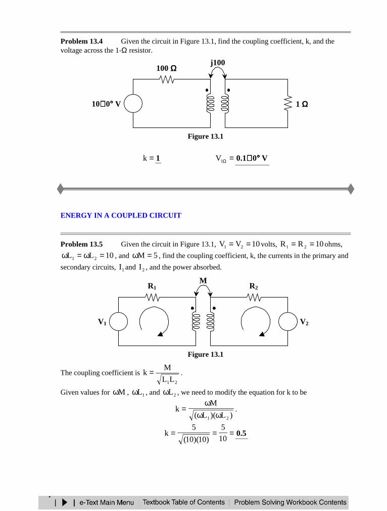
Problem 13.4 Given the circuit in Figure 13.1, find the coupling coefficient, k, and thevoltage across the 1-Ω resistor.
Figure 13.1
=k 1 =Ω1V V01.0 °°°°∠∠∠ ∠
ENERGY IN A COUPLED CIRCUIT
Problem 13.5 Given the circuit in Figure 13.1, 10VV 21 == volts, 10RR 21 == ohms,
10LL 21 =ω=ω , and 5M =ω , find the coupling coefficient, k, the currents in the primary and
secondary circuits, 1I and 2I , and the power absorbed.
Figure 13.1
The coupling coefficient is 21LL
Mk = .
Given values for Mω , 1Lω , and 2Lω , we need to modify the equation for k to be
)L)(L(
Mk
21 ωωω
= .
===10
5
)10)(10(
5k 5.0
100 ΩΩΩΩ
10∠∠∠ ∠ 0°°°° V +−
j100
j100 ΩΩΩΩj100 ΩΩΩΩ 1 ΩΩΩΩ+
V1ΩΩΩΩ
R2R1
+−
V1 V2+−
I1 I2
M
L2L1
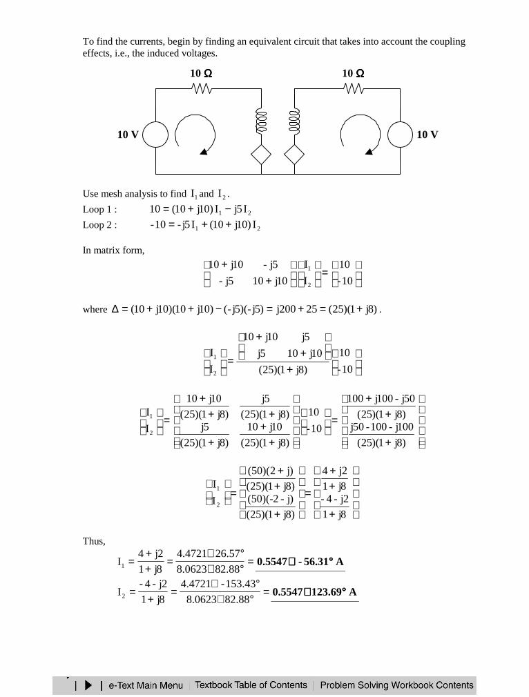
To find the currents, begin by finding an equivalent circuit that takes into account the couplingeffects, i.e., the induced voltages.
Use mesh analysis to find 1I and 2I .
Loop 1 : 21 I5jI)10j10(10 −+=Loop 2 : 21 I)10j10(I5j-10- ++=
In matrix form,
=
+
+10-
10
I
I
10j105j-
5j-10j10
2
1
where )8j1)(25(25200j)5j-)(5j-()10j10)(10j10( +=+=−++=∆ .
+
+
+
=
10-
10
)8j1)(25(
10j105j
5j10j10
I
I
2
1
+
++
=
++
+
+++
=
)8j1)(25(
100j-100-50j)8j1)(25(
50j-100j100
10-
10
)8j1)(25(
10j10
)8j1)(25(
5j)8j1)(25(
5j
)8j1)(25(
10j10
I
I
2
1
+
++
=
+
++
=
8j1
2j-4-8j1
2j4
)8j1)(25(
)j-2-)(50()8j1)(25(
)j2)(50(
I
I
2
1
Thus,
=°∠°∠
=++
=88.820623.8
57.264721.4
8j1
2j4I1 A31.56-5547.0 °°°°∠∠∠∠
=°∠°∠
=+
=88.820623.8
43.153-4721.4
8j1
2j-4-I2 A69.1235547.0 °°°°∠∠∠∠
10 ΩΩΩΩ10 ΩΩΩΩ
+−
10 V 10 V+−
I1 I2
j10 ΩΩΩΩj10 ΩΩΩΩ
−+
+− j5I1j5I2
Now, find the power absorbed in the circuit. Look at the power absorbed by each element.
Starting with the primary circuit,W0769.3-))31.56-(0cos()5547.0((10)-cosIV-p 1V =°−°=θ=
W0769.3)10()5547.0(RIp 21
211R ===
W0)270cos(5385.1))31.56-(69.213cos()5547.0)(7735.2(-p1 =°=°−°=where 1p is the power absorbed by the induced voltage of 1L .
Ending with the secondary circuit,W0769.3-)69.1230cos()5547.0)(10(cosIVp 2V =°−°=θ=
W0769.3)10()5547.0(RIp 22
222R ===
W0)90cos(5385.1)69.12369.33cos()5547.0)(7735.2(-p2 =°=°−°=where 2p is the power absorbed by the induced voltage of 2L .
The voltage sources absorb –3.0769 watts, or deliver +3.0769 watts, the resistances absorb3.0769 watts, and the induced voltages absorb 0 watts. The inductors do not absorb power.
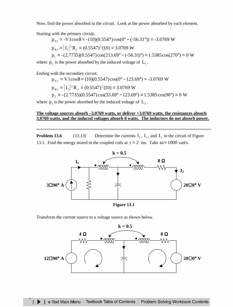
Problem 13.6 [13.13] Determine the currents 1I , 2I , and 3I in the circuit of Figure
13.1. Find the energy stored in the coupled coils at 2t = ms. Take 1000=ω rad/s.
Figure 13.1
Transform the current source to a voltage source as shown below.
4 ΩΩΩΩ –j5 ΩΩΩΩ
8 ΩΩΩΩ
3∠∠∠∠ 90°°°° A 20∠∠∠∠ 0°°°° V+−
I2
I1
k = 0.5
j10 ΩΩΩΩ j10 ΩΩΩΩI3
–j5 ΩΩΩΩ
8 ΩΩΩΩ
12∠∠∠∠ 90°°°° A 20∠∠∠∠ 0°°°° V+−
k = 0.5
j10 ΩΩΩΩ j10 ΩΩΩΩI3
+−
4 ΩΩΩΩ
I2I1
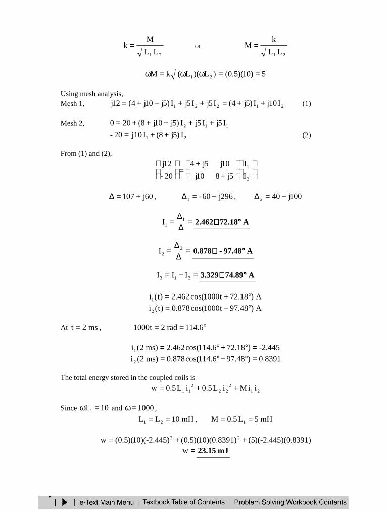
21 LL
Mk = or
21 LL
kM =
5)10)(5.0()L)(L(kM 21 ==ωω=ω
Using mesh analysis,Mesh 1, 21221 I10jI)5j4(I5jI5jI)5j10j4(12j ++=++−+= (1)
Mesh 2, 112 I5jI5jI)5j10j8(200 ++−++=
21 I)5j8(Ij1020- ++= (2)
From (1) and (2),
++
=
2
1
I
I
5j810j
10j5j4
20-
12j
60j107 +=∆ , 296j60-1 −=∆ , 100j402 −=∆
=∆∆
= 11I A18.72462.2 °°°°∠∠∠∠
=∆∆
= 22I A97.48-878.0 °°°°∠∠∠∠
=−= 213 III A89.74329.3 °°°°∠∠∠∠
A)18.72t1000cos(462.2)t(i1 °+=A)48.97t1000cos(878.0)t(i2 °−=
At ms2t = , °== 6.114rad2t1000
-2.445)18.726.114cos(462.2)ms2(i1 =°+°=0.8391)48.976.114cos(878.0)ms2(i2 =°−°=
The total energy stored in the coupled coils is
212
222
11 iiMiL5.0iL5.0w ++=
Since 10L1 =ω and 1000=ω ,
mH10LL 21 == , mH5L5.0M 1 ==
8391)-2.445)(0.)(5(0.8391))(10)(5.0(-2.445))(10)(5.0(w 22 ++==w mJ15.23
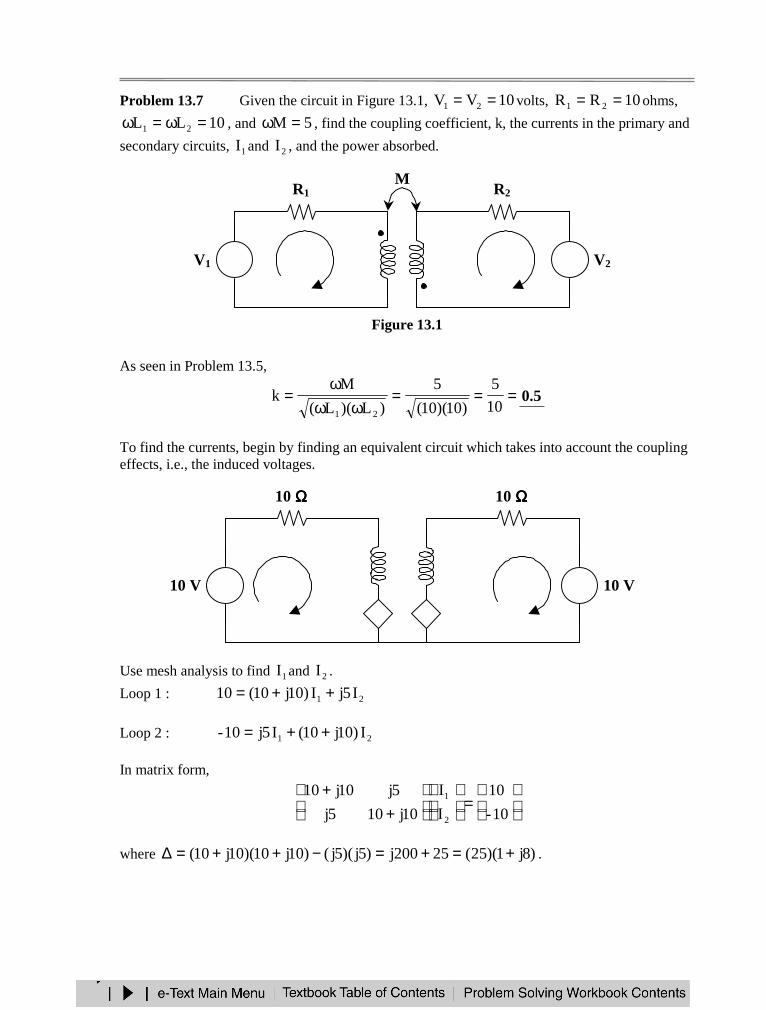
Problem 13.7 Given the circuit in Figure 13.1, 10VV 21 == volts, 10RR 21 == ohms,
10LL 21 =ω=ω , and 5M =ω , find the coupling coefficient, k, the currents in the primary and
secondary circuits, 1I and 2I , and the power absorbed.
Figure 13.1
As seen in Problem 13.5,
===ωω
ω=
10
5
)10)(10(
5
)L)(L(
Mk
21
5.0
To find the currents, begin by finding an equivalent circuit which takes into account the couplingeffects, i.e., the induced voltages.
Use mesh analysis to find 1I and 2I .
Loop 1 : 21 I5jI)10j10(10 ++=
Loop 2 : 21 I)10j10(I5j10- ++=
In matrix form,
=
++
10-
10
I
I
10j105j
5j10j10
2
1
where )8j1)(25(25200j)5j)(5j()10j10)(10j10( +=+=−++=∆ .
R2R1
+−
V1 V2+−
I1 I2
M
L2L1
10 ΩΩΩΩ10 ΩΩΩΩ
+−
10 V 10 V+−
I1 I2
j10 ΩΩΩΩj10 ΩΩΩΩ
−+
+− j5I1j5I2
+
++
=
10-
10
)8j1)(25(
10j105j-
5j-10j10
I
I
2
1
+
+++
=
++
+
+++
=
)8j1)(25(
100j-100-50j-)8j1)(25(
50j100j100
10-
10
)8j1)(25(
10j10
)8j1)(25(
5j-)8j1)(25(
5j-
)8j1)(25(
10j10
I
I
2
1
+
++
=
+
++
=
8j1
6j-4-8j1
6j4
)8j1)(25(
)3j-2-)(50()8j1)(25(
)3j2)(50(
I
I
2
1
Thus,
=°∠°∠
=++
=88.820623.8
31.562111.7
8j1
6j4I1 A57.62-8944.0 °°°°∠∠∠∠
=°∠°∠
=+
=88.820623.8
69.123-2111.7
8j1
6j-4-I2 A43.1538944.0 °°°°∠∠∠∠
Now, find the power absorbed in the circuit. Look at the power absorbed by each element.
Starting with the primary circuit,W9994.7-))57.26-(0cos()8944.0(10)(-cosIV-p 1V =°−°=θ=
W9995.7)10()8944.0(RIp 21
211R ===
W0)270cos(9998.3))57.26-(43.243cos()8944.0)(4720.4(p1 =°=°−°=where 1p is the power absorbed by the induced voltage of 1L .
Ending with the secondary circuit,W9994.7-)43.1530cos()8944.0)(10(cosIVp 2V =°−=θ=
W9995.7)10()8944.0(RIp 22
222R ===
W0)90-cos(9998.3)43.15343.63cos()8944.0)(4720.4(p2 =°=°−°=where 2p is the power absorbed by the induced voltage of 2L .
The voltage sources absorb –7.9994 watts, or deliver +7.9994 watts, the resistances absorb7.9995 watts, and the induced voltages absorb 0 watts. The inductors do not absorb power.
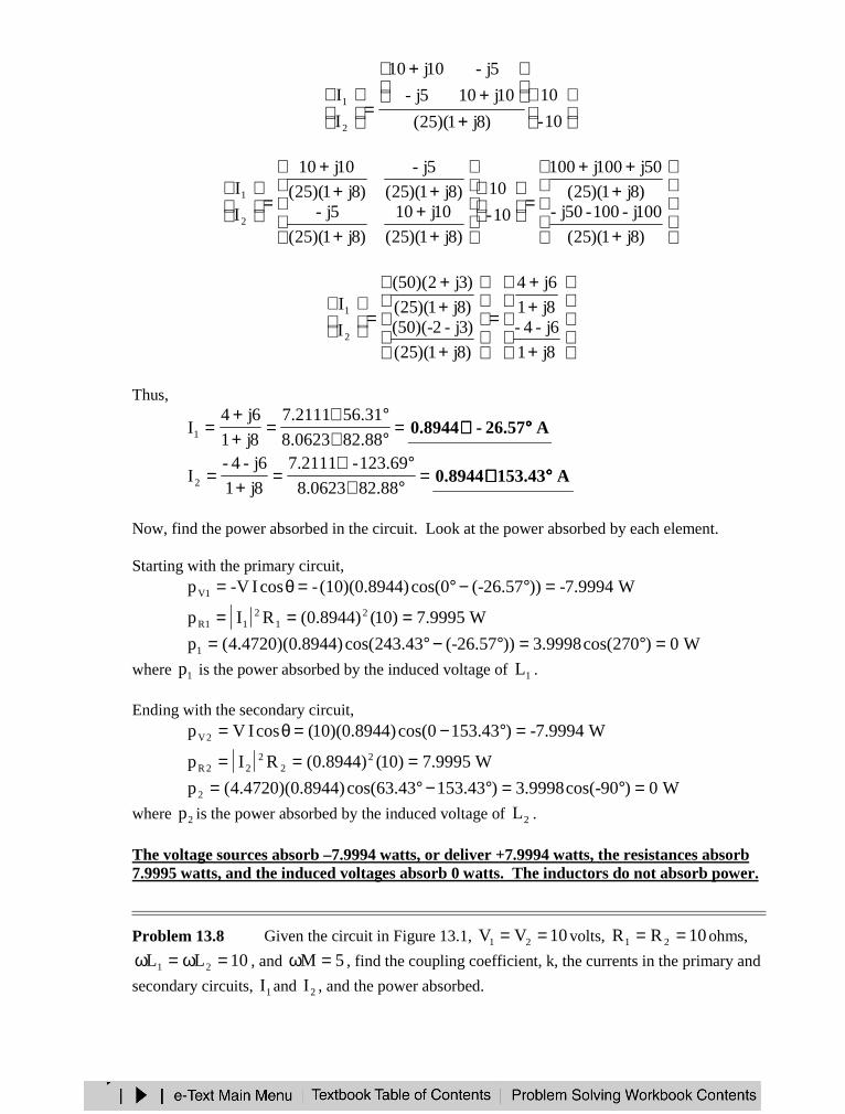
Problem 13.8 Given the circuit in Figure 13.1, 10VV 21 == volts, 10RR 21 == ohms,
10LL 21 =ω=ω , and 5M =ω , find the coupling coefficient, k, the currents in the primary and
secondary circuits, 1I and 2I , and the power absorbed.
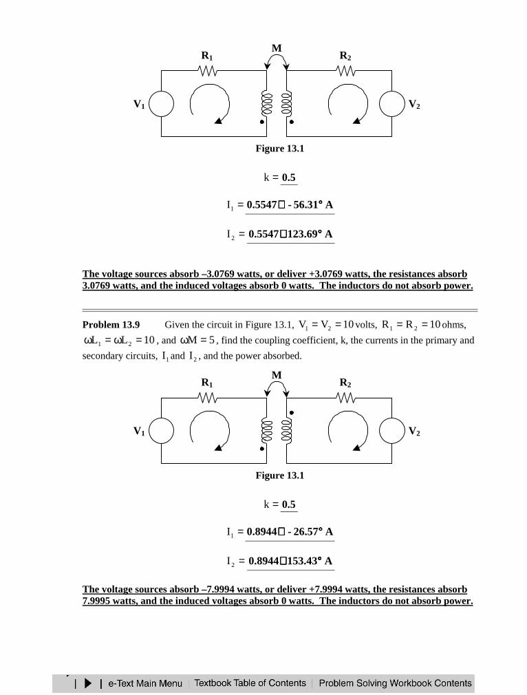
Figure 13.1
=k 5.0
=1I A31.56-5547.0 °°°°∠∠∠∠
=2I A69.1235547.0 °°°°∠∠∠∠
The voltage sources absorb –3.0769 watts, or deliver +3.0769 watts, the resistances absorb3.0769 watts, and the induced voltages absorb 0 watts. The inductors do not absorb power.
Problem 13.9 Given the circuit in Figure 13.1, 10VV 21 == volts, 10RR 21 == ohms,
10LL 21 =ω=ω , and 5M =ω , find the coupling coefficient, k, the currents in the primary and
secondary circuits, 1I and 2I , and the power absorbed.
Figure 13.1
=k 5.0
=1I A57.62-8944.0 °°°°∠∠∠∠
=2I A43.1538944.0 °°°°∠∠∠∠
The voltage sources absorb –7.9994 watts, or deliver +7.9994 watts, the resistances absorb7.9995 watts, and the induced voltages absorb 0 watts. The inductors do not absorb power.
R2R1
+−
V1 V2+−
I1 I2
M
L2L1
R2R1
+−
V1 V2+−
I1 I2
M
L2L1
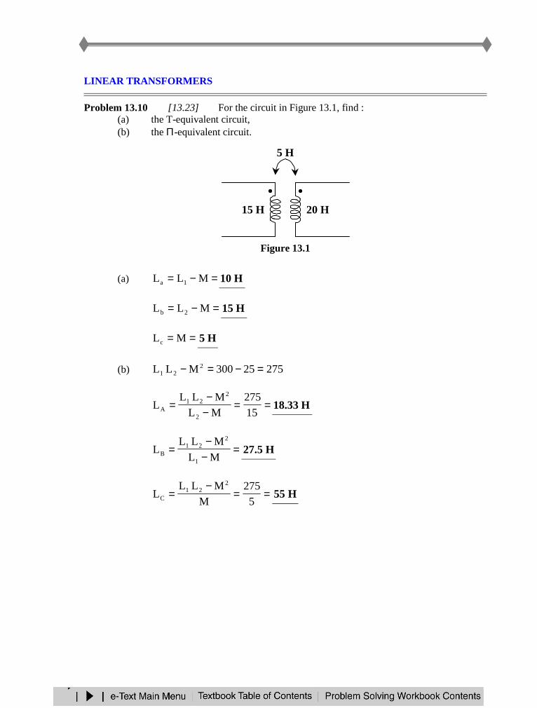
LINEAR TRANSFORMERS
Problem 13.10 [13.23] For the circuit in Figure 13.1, find :(a) the T-equivalent circuit,(b) the Π-equivalent circuit.
Figure 13.1
(a) =−= MLL 1a H10
=−= MLL 2b H15
== MLc H5
(b) 27525300MLL 221 =−=−
==−−
=15
275
ML
MLLL
2
221
A H33.18
=−−
=ML
MLLL
1
221
B H5.27
==−
=5
275M
MLLL
221
C H55
5 H
20 H15 H
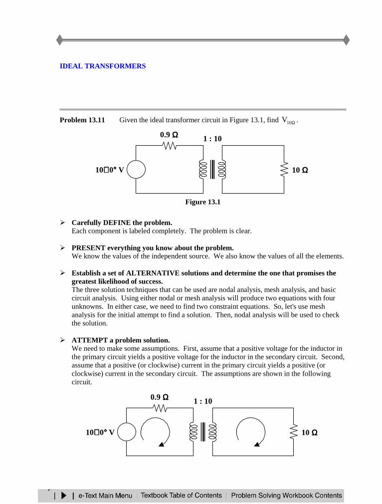
IDEAL TRANSFORMERS
Problem 13.11 Given the ideal transformer circuit in Figure 13.1, find Ω10V .
Figure 13.1
Carefully DEFINE the problem.Each component is labeled completely. The problem is clear.
PRESENT everything you know about the problem.We know the values of the independent source. We also know the values of all the elements.
Establish a set of ALTERNATIVE solutions and determine the one that promises thegreatest likelihood of success.The three solution techniques that can be used are nodal analysis, mesh analysis, and basiccircuit analysis. Using either nodal or mesh analysis will produce two equations with fourunknowns. In either case, we need to find two constraint equations. So, let's use meshanalysis for the initial attempt to find a solution. Then, nodal analysis will be used to checkthe solution.
ATTEMPT a problem solution.We need to make some assumptions. First, assume that a positive voltage for the inductor inthe primary circuit yields a positive voltage for the inductor in the secondary circuit. Second,assume that a positive (or clockwise) current in the primary circuit yields a positive (orclockwise) current in the secondary circuit. The assumptions are shown in the followingcircuit.
0.9 ΩΩΩΩ
10∠∠∠ ∠ 0°°°° V +− 10 ΩΩΩΩ
+
V10ΩΩΩΩ
1 : 10
0.9 ΩΩΩΩ
10∠∠∠ ∠ 0°°°° V +− 10 ΩΩΩΩ
+
V10ΩΩΩΩ
1 : 10
I1 I2
+
V2
−−−−
+
V1
−−−−

Mesh analysis yields,Loop 1 : 11 VI9.010 +=
Loop 2 : 22 I10V =
This is a set of two equations and four unknowns. Two constraint equations are needed.
From the ideal transformer, as shown, we know that 12 nVV = and 21 nII = .
This implies that
12 V10V = and 21 I10I =which are the two constraint equations.
There are many ways to find the values of 1V , 2V , 1I , and 2I . Let's find 1I . To do this,
find 1V in terms of 1I and substitute into the equation for loop 1.
12221 I1.0I)I10)(1.0(V1.0V ====
and the equation for loop 1 becomes
11 I1.0I9.010 +=
1I10 =Hence,
A10I1 = V1V1 =A1I2 = V10V2 =
Therefore,==Ω 210 VV V10
EVALUATE the solution and check for accuracy.Using nodal analysis,
At node 1, 0I9.0
10V1
1 =+−
or 0I9.010V 11 =+− (1)
At node 2, 0)I-(10
0V2
2 =+−
or 0I10V 22 =− (2)
VS+−
ZL
1 : n
I1 I2
+
V2
−−−−
+
V1
−−−−
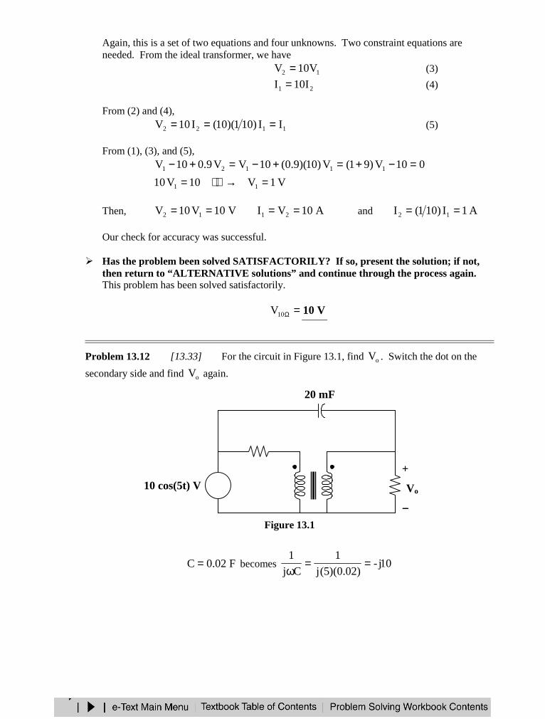
Again, this is a set of two equations and four unknowns. Two constraint equations areneeded. From the ideal transformer, we have
12 V10V = (3)
21 I10I = (4)
From (2) and (4),
1122 II)101)(10(I10V === (5)
From (1), (3), and (5),010V)91(V)10)(9.0(10VV9.010V 11121 =−+=+−=+−
V1V10V10 11 =→=
Then, V10V10V 12 == A10VI 21 == and A1I)101(I 12 ==
Our check for accuracy was successful.
Has the problem been solved SATISFACTORILY? If so, present the solution; if not,then return to “ALTERNATIVE solutions” and continue through the process again.This problem has been solved satisfactorily.
=Ω10V V10
Problem 13.12 [13.33] For the circuit in Figure 13.1, find oV . Switch the dot on the
secondary side and find oV again.
Figure 13.1
F02.0C = becomes 10j-)02.0)(5(j
1
Cj
1==
ω
2 ΩΩΩΩ
20 mF
10 ΩΩΩΩ
10 cos(5t) V +−
+
Vo
−−−−
3 : 1
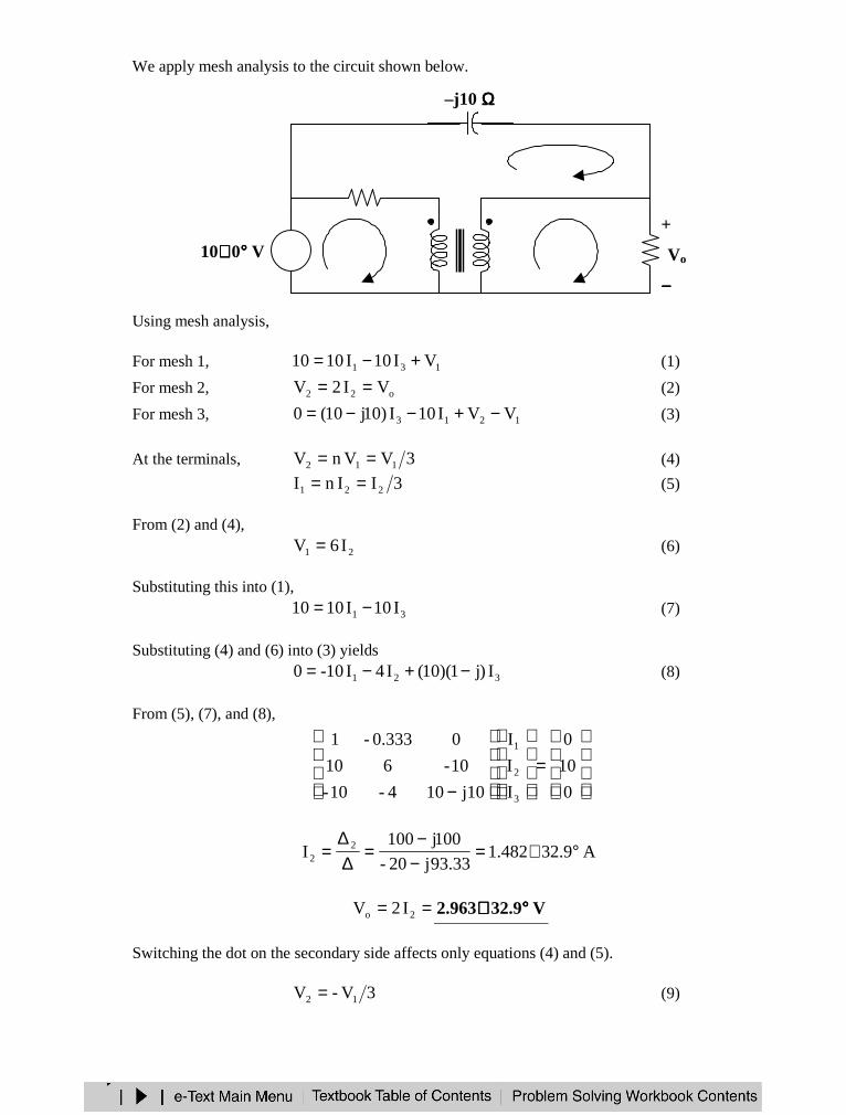
We apply mesh analysis to the circuit shown below.
Using mesh analysis,
For mesh 1, 131 VI10I1010 +−= (1)
For mesh 2, o22 VI2V == (2)
For mesh 3, 1213 VVI10I)10j10(0 −+−−= (3)
At the terminals, 3VVnV 112 == (4)
3IInI 221 == (5)
From (2) and (4),
21 I6V = (6)
Substituting this into (1),
31 I10I1010 −= (7)
Substituting (4) and (6) into (3) yields
321 I)j1)(10(I4I10-0 −+−= (8)
From (5), (7), and (8),
=
− 0
10
0
I
I
I
j10104-10-
10-610
00.333-1
3
2
1
A9.32482.193.33j20-
100j100I 2
2 °∠=−−
=∆∆
=
== 2o I2V V9.32963.2 °°°°∠∠∠∠
Switching the dot on the secondary side affects only equations (4) and (5).
3V-V 12 = (9)
2 ΩΩΩΩ
–j10 ΩΩΩΩ
10 ΩΩΩΩ
+−
+
Vo
−−−−
3 : 1
10∠∠∠∠ 0°°°° V I1 I2
I3
+
V2
−−−−
+
V1
−−−−
3I-I 21 = (10)
From (2) and (9),
21 I-6V =
Substituting this into (1),
1231 I)5j23(I6I10I1010 −=−−= (11)
Substituting (9) and (10) into (3),
321 I)j1)(10(I4I10-0 −++= (12)
From (10) to (12), we get
=
− 0
10
0
I
I
I
10j10410-
10-6-10
0333.01
3
2
1
A147.1-482.193.33j20-
100j100I 2
2 °∠=+−
=∆∆
=
== 2o I2V V147.1-963.2 °°°°∠∠∠ ∠
THREE-PHASE TRANSFORMERS
Problem 13.13 [13.53] In order to meet an emergency, three single-phase transformerswith rmsV7200470,12 are connected in Y−∆ to form a three-phase transformer which isfed by a 12,470-V transmission line. If the transformer supplies 60 MVA to a load, find :
(a) the turns ratio for each transformer,(b) the currents in the primary and secondary windings of the transformer,(c) the incoming and outgoing transmission line currents.
(a) Consider just one phase at a time.
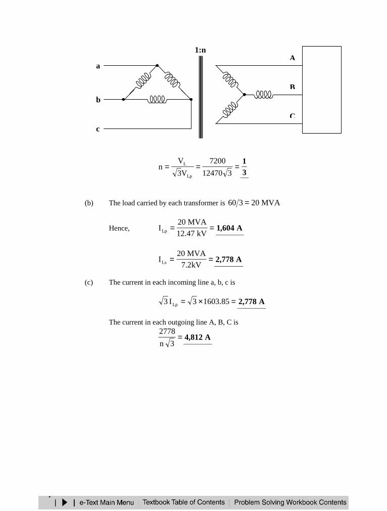
===312470
7200
V3
Vn
Lp
L
31
(b) The load carried by each transformer is MVA20360 =
Hence, ==kV47.12
MVA20ILp A604,1
==kV2.7
MVA20ILs A778,2
(c) The current in each incoming line a, b, c is
=×= 85.16033I3 Lp A778,2
The current in each outgoing line A, B, C is
=3n
2778A812,4
1:n
c
b
a
C
20MVALoad
B
A

PSPICE ANALYSIS OF MAGNETICALLY COUPLED CIRCUITS
Problem 13.14 [13.63] Use PSpice to find 1V , 2V , and oI in the circuit in Figure 13.1.
Figure 13.1
The schematic is shown below.
In the AC Sweep box, we type Total Pts = 1, Start Freq = 0.1592, and End Freq = 0.1592.After simulation, we obtain the output file which includes
FREQ IM(V_PRINT1) IP(V_PRINT1)1.592 E–01 1.955 E+01 8.332 E+01
FREQ IM(V_PRINT2) IP(V_PRINT2)1.592 E–01 6.847 E+01 4.640 E+01
FREQ IM(V_PRINT3) IP(V_PRINT3)1.592 E–01 4.434 E–01 –9.260 E+01
–j12 ΩΩΩΩ2 ΩΩΩΩ
+−
1 : 2
40∠∠∠ ∠ 60°°°° V
+
V2
−−−−
+
V1
−−−−
16 ΩΩΩΩ
–j4 ΩΩΩΩ 20 ΩΩΩΩ
j8 ΩΩΩΩ
30∠∠∠ ∠ 0°°°° V+−
Io
Thus,=1V V32.8355.19 °°°°∠∠∠ ∠ =2V V4.4647.68 °°°°∠∠∠ ∠
=oI mA92.6-4.443 °°°°∠∠∠ ∠
APPLICATIONS
Problem 13.15 [13.73] A 4800-V rms transmission line feeds a distribution transformerwith 1200 turns on the primary and 28 turns on the secondary. When a 10-Ω load is connectedacross the secondary, find :
(a) the secondary voltage,(b) the primary and secondary currents,(c) the power supplied to the load.
(a) nN
N
V
V
1
2
1
2 ==
=
== )4800(1200
28V
N
NV 1
1
22 V112
(b) ===10
112
R
VI 2
2 A2.11
21 InI = , where 120028n =
=
= )2.11(1200
28I1 mA3.261
(c) === )10()2.11(RIp 22
2 W1254
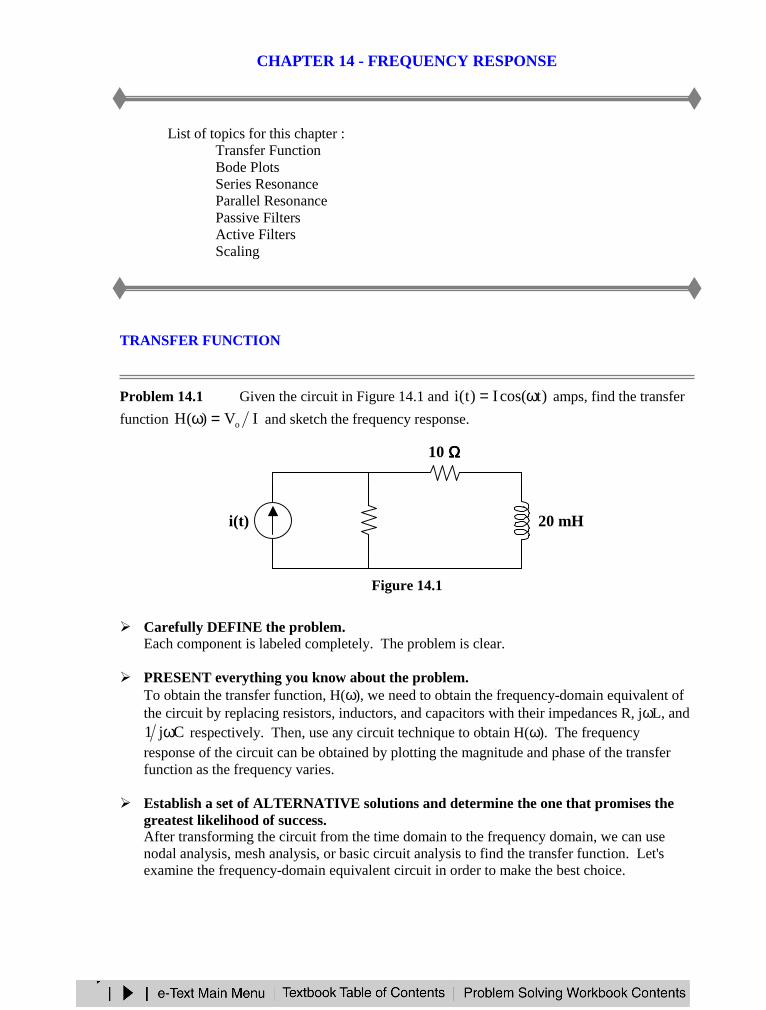
CHAPTER 14 - FREQUENCY RESPONSE
List of topics for this chapter :Transfer FunctionBode PlotsSeries ResonanceParallel ResonancePassive FiltersActive FiltersScaling
TRANSFER FUNCTION
Problem 14.1 Given the circuit in Figure 14.1 and )tcos(I)t(i ω= amps, find the transfer
function IV)(H o=ω and sketch the frequency response.
Figure 14.1
Carefully DEFINE the problem.Each component is labeled completely. The problem is clear.
PRESENT everything you know about the problem.To obtain the transfer function, H(ω), we need to obtain the frequency-domain equivalent ofthe circuit by replacing resistors, inductors, and capacitors with their impedances R, jωL, and
Cj1 ω respectively. Then, use any circuit technique to obtain H(ω). The frequencyresponse of the circuit can be obtained by plotting the magnitude and phase of the transferfunction as the frequency varies.
Establish a set of ALTERNATIVE solutions and determine the one that promises thegreatest likelihood of success.After transforming the circuit from the time domain to the frequency domain, we can usenodal analysis, mesh analysis, or basic circuit analysis to find the transfer function. Let'sexamine the frequency-domain equivalent circuit in order to make the best choice.
i(t)
10 ΩΩΩΩ
10 ΩΩΩΩ 20 mH
+
vo(t)
−−−−
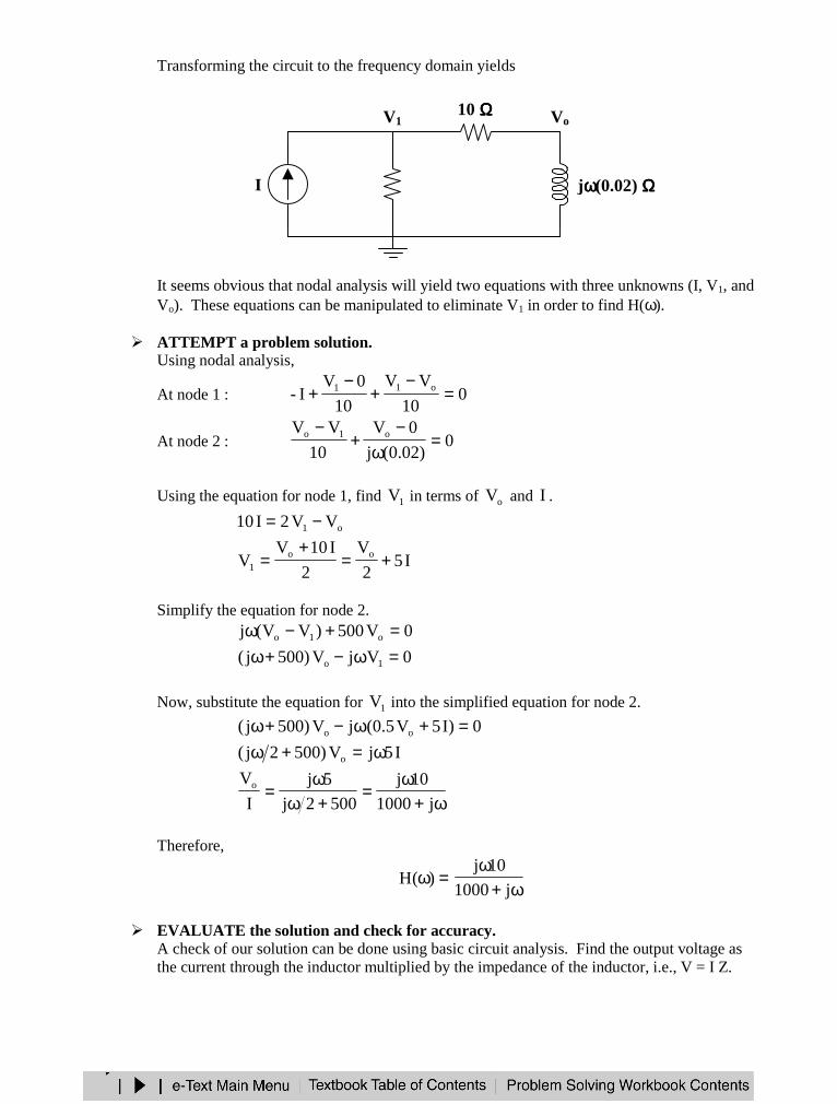
Transforming the circuit to the frequency domain yields
It seems obvious that nodal analysis will yield two equations with three unknowns (I, V1, andVo). These equations can be manipulated to eliminate V1 in order to find H(ω).
ATTEMPT a problem solution.Using nodal analysis,
At node 1 : 010
VV
10
0VI- o11 =
−+
−+
At node 2 : 0)02.0(j
0V
10
VV o1o =ω
−+
−
Using the equation for node 1, find 1V in terms of oV and I .
o1 VV2I10 −=
I52
V
2
I10VV oo
1 +=+
=
Simplify the equation for node 2.0V500)VV(j o1o =+−ω0VjV)500j( 1o =ω−+ω
Now, substitute the equation for 1V into the simplified equation for node 2.
0)I5V5.0(jV)500j( oo =+ω−+ωI5jV)5002j( o ω=+ω
ω+ω
=+ω
ω=
j1000
10j
5002j
5j
I
Vo
Therefore,
=ω)(Hω+
ωj1000
10j
EVALUATE the solution and check for accuracy.A check of our solution can be done using basic circuit analysis. Find the output voltage asthe current through the inductor multiplied by the impedance of the inductor, i.e., V = I Z.
I
10 ΩΩΩΩ
10 ΩΩΩΩ jωωωω(0.02) ΩΩΩΩ
V1 Vo
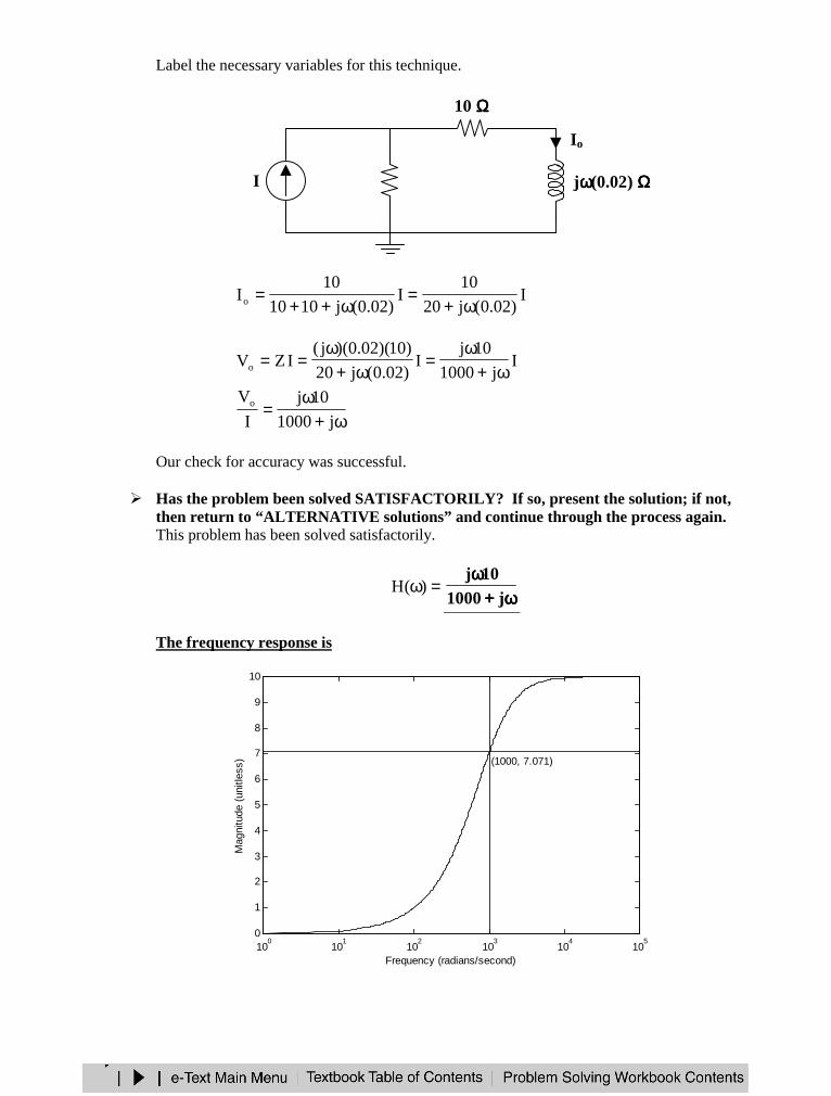
Label the necessary variables for this technique.
I)02.0(j20
10I
)02.0(j1010
10Io ω+
=ω++
=
Ij1000
10jI
)02.0(j20
)10)(02.0)(j(IZVo ω+
ω=
ω+ω
==
ω+ω
=j1000
10j
I
Vo
Our check for accuracy was successful.
Has the problem been solved SATISFACTORILY? If so, present the solution; if not,then return to “ALTERNATIVE solutions” and continue through the process again.This problem has been solved satisfactorily.
=ω)(Hωωωω++++
ωωωωj1000
10j
The frequency response is
I
10 ΩΩΩΩ
10 ΩΩΩΩ jωωωω(0.02) ΩΩΩΩ
Io+
Vo
−−−−
100
101
102
103
104
105
0
1
2
3
4
5
6
7
8
9
10
Frequency (radians/second)
Mag
nitu
de (
unitl
ess) (1000, 7.071)

Problem 14.2 Given the circuit in Figure 14.1 and )tcos(V)t(v inin ω= volts, find the
transfer function inout VV)(H =ω and sketch the frequency response.
Figure 14.1
Transform the circuit to the frequency domain.
Clearly,I)01.0(jVout ω=
and
)01.0(j10j
10
VI 6
4
in
ω+ω
−=
Thus,
I)01.0(j10j
10V6
4in
ω+ω
−=
So,
ω−ω+
ω=
ω+ω
−
ω=
86
64in
out
10j10
j
I)01.0(j10j
10
I)01.0(j
V
V
Therefore,
=ω)(H
ωωωω−−−−ωωωω++++
ωωωω8
6 10j10
j
jωωωω0.01 ΩΩΩΩVin+−
10 kΩΩΩΩ –j106/ωωωω ΩΩΩΩ
+
Vout
−−−−
I
+−
10 kΩΩΩΩ 1 µµµµF
10 mH
+
vout(t)
−−−−
Ivin(t)
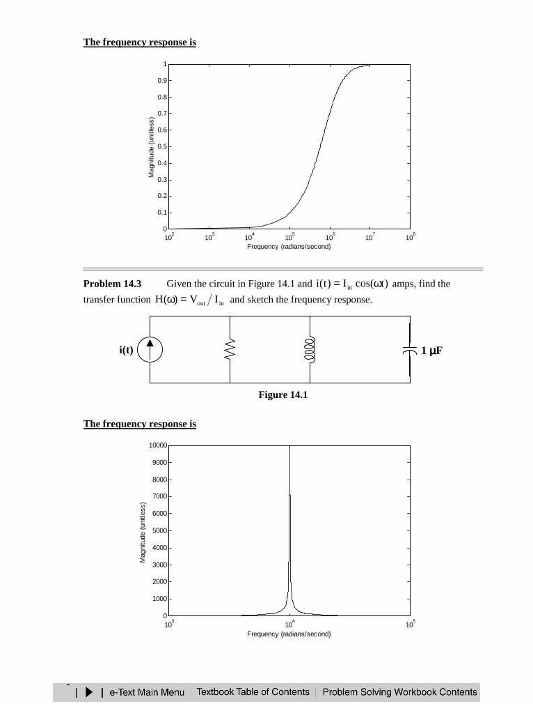
The frequency response is
Problem 14.3 Given the circuit in Figure 14.1 and )tcos(I)t(i in ω= amps, find the
transfer function inout IV)(H =ω and sketch the frequency response.
Figure 14.1
The frequency response is
i(t) 10 kΩΩΩΩ 10 mH 1 µµµµF
+
vout(t)
−−−−
103
104
105
0
1000
2000
3000
4000
5000
6000
7000
8000
9000
10000
Frequency (radians/second)
Mag
nitu
de (
unitl
ess)
102
103
104
105
106
107
108
0
0.1
0.2
0.3
0.4
0.5
0.6
0.7
0.8
0.9
1
Frequency (radians/second)
Mag
nitu
de (
unitl
ess)
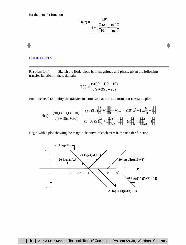
for the transfer function
=ω)(H
ωωωω−−−−
ωωωω++++
6
2
4
1010
j1
10
BODE PLOTS
Problem 14.4 Sketch the Bode plots, both magnitude and phase, given the followingtransfer function in the s-domain.
)30s)(3s(s
)10s)(1s)(90()s(H
++++
=
First, we need to modify the transfer function so that it is in a form that is easy to plot.
+
+
+
+=
+
+
+
+=
++++
=1
30
s1
3
s)s(
110
s1
1
s)10(
130
s1
3
s)s)(30)(3(
110
s1
1
s)10)(90(
)30s)(3s(s
)10s)(1s)(90()s(H
Begin with a plot showing the magnitude curve of each term in the transfer function.
0.1 0.3 1 3 10 30
–
20
20 log10(10)
20 log10(j(ωωωω/10)+1)
20 log10(1/[j(ωωωω/30)+1])
20 log10(jωωωω + 1)
20 log10(1/ωωωω)
20 log10(1/[j(ωωωω/3)+1])
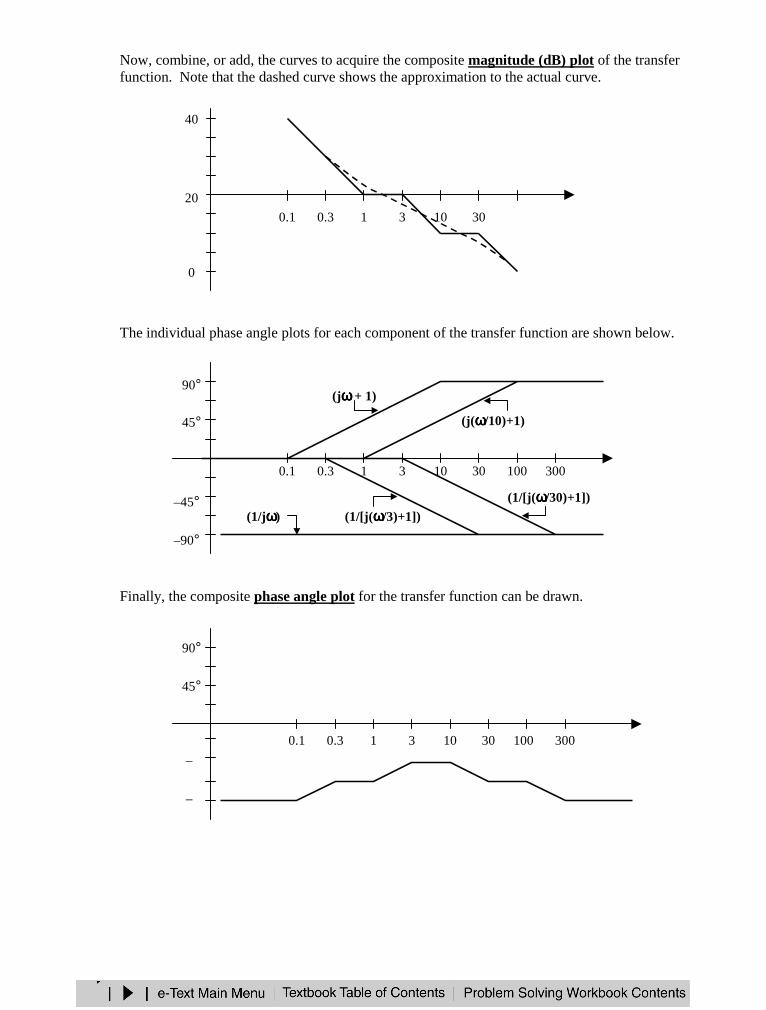
Now, combine, or add, the curves to acquire the composite magnitude (dB) plot of the transferfunction. Note that the dashed curve shows the approximation to the actual curve.
The individual phase angle plots for each component of the transfer function are shown below.
Finally, the composite phase angle plot for the transfer function can be drawn.
0.1 0.3 1 3 10 30
20
40
0
0.1 0.3 1 3 10 30
–90°
90°
(j(ωωωω/10)+1)
(1/[j(ωωωω/30)+1])
(jωωωω + 1)
(1/jωωωω) (1/[j(ωωωω/3)+1])
100 300
–45°
45°
0.1 0.3 1 3 10 30
–
90°
100 300
–
45°
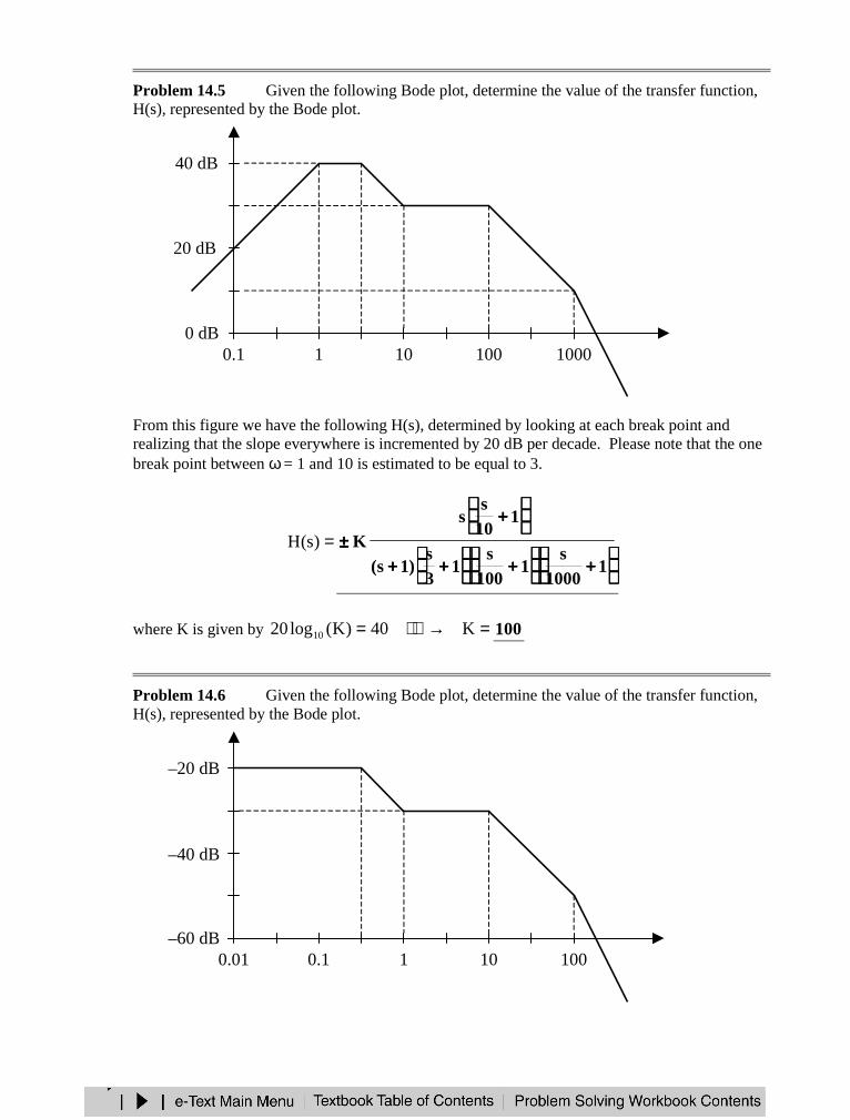
Problem 14.5 Given the following Bode plot, determine the value of the transfer function,H(s), represented by the Bode plot.
From this figure we have the following H(s), determined by looking at each break point andrealizing that the slope everywhere is incremented by 20 dB per decade. Please note that the onebreak point between ω = 1 and 10 is estimated to be equal to 3.
=)s(H
++++
++++
++++++++
++++±±±±
11000
s1
100s
13s
)1s(
110s
sK
where K is given by =→= K40)K(log20 10 100
Problem 14.6 Given the following Bode plot, determine the value of the transfer function,H(s), represented by the Bode plot.
40 dB
20 dB
100 10001010.10 dB
10 10010.10.01
–20 dB
–40 dB
–60 dB
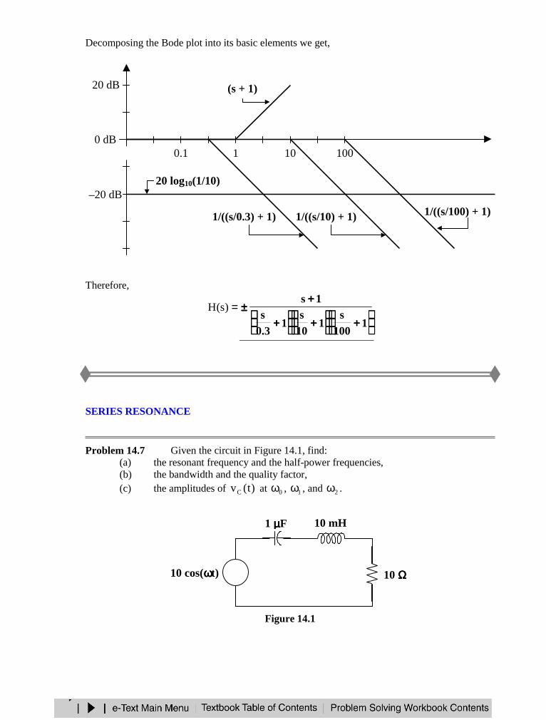
Decomposing the Bode plot into its basic elements we get,
Therefore,
=)s(H
++++
++++
++++
++++±±±±
1100
s1
10s
13.0
s1s
SERIES RESONANCE
Problem 14.7 Given the circuit in Figure 14.1, find:(a) the resonant frequency and the half-power frequencies,(b) the bandwidth and the quality factor,(c) the amplitudes of )t(vC at 0ω , 1ω , and 2ω .
Figure 14.1
+−10 cos(ωωωωt)
10 mH
+
vout(t)
−−−−
10 ΩΩΩΩ
1 µµµµF
+ −vC(t)
10 10010.1
20 dB
–20 dB
0 dB0.01
1/((s/0.3) + 1)
20 log10(1/10)
1/((s/10) + 1) 1/((s/100) + 1)
(s + 1)
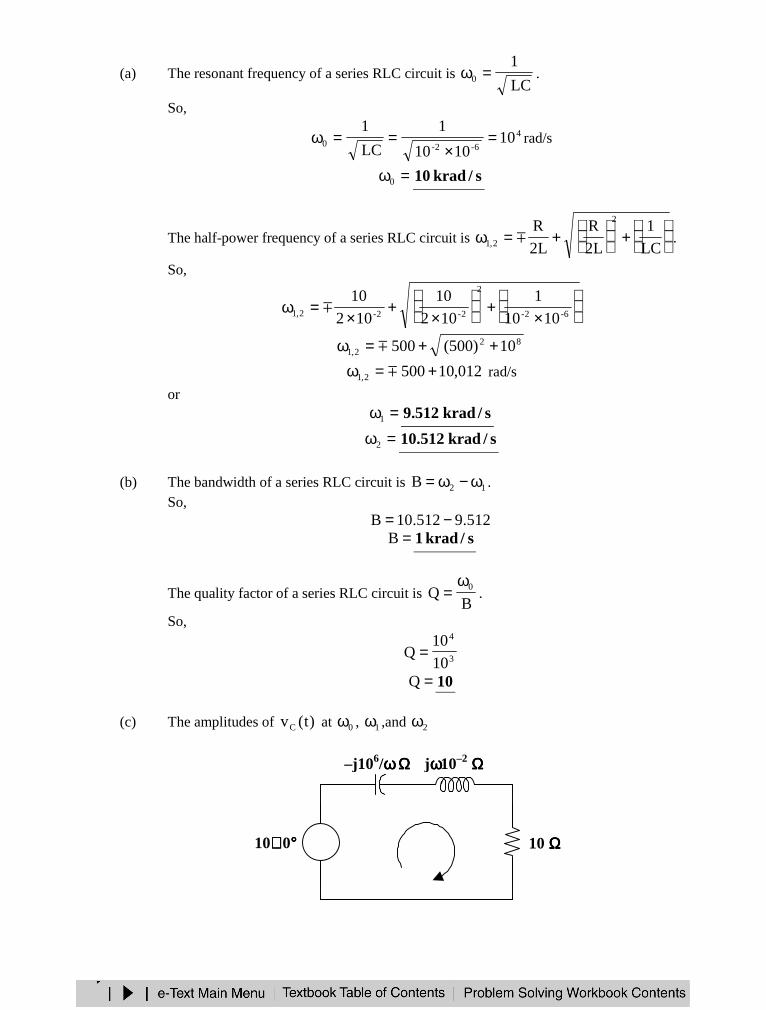
(a) The resonant frequency of a series RLC circuit is LC
10 =ω .
So,
4
6-2-0 101010
1
LC
1=
×==ω rad/s
=ω0 s/krad10
The half-power frequency of a series RLC circuit is
+
+=ωLC
1
L2
R
L2
R 2
2,1 .
So,
×+
×+
×=ω 6-2-
2
2-2-2,1 1010
1
102
10
102
10
822,1 10)500(500 ++=ω
012,105002,1 +=ω rad/s
or=ω1 s/krad512.9
=ω2 s/krad512.10
(b) The bandwidth of a series RLC circuit is 12B ω−ω= .So,
512.9512.10B −==B s/krad1
The quality factor of a series RLC circuit is B
Q 0ω= .
So,
3
4
10
10Q =
=Q 10
(c) The amplitudes of )t(vC at 0ω , 1ω ,and 2ω
+−
+
Vout
−−−−
jωωωω10–2 ΩΩΩΩ
I10∠∠∠∠ 0°°°° 10 ΩΩΩΩ
+ −VC
–j106/ωωωω ΩΩΩΩ
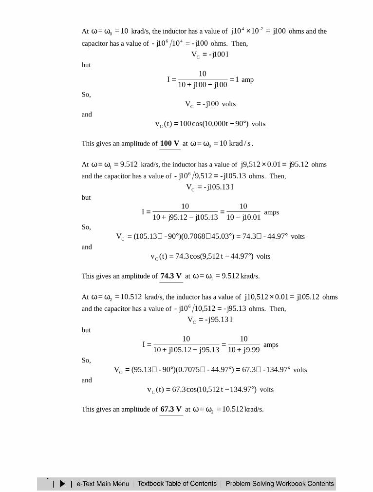
At 100 =ω=ω krad/s, the inductor has a value of 100j10j10 2-4 =× ohms and the
capacitor has a value of 100j-1010j- 46 = ohms. Then,
I100j-VC =but
1100j100j10
10I =
−+= amp
So,100j-VC = volts
and)90t000,10cos(100)t(vC °−= volts
This gives an amplitude of V100 at s/krad100 =ω=ω .
At 512.91 =ω=ω krad/s, the inductor has a value of 12.95j01.0j9,512 =× ohms
and the capacitor has a value of 13.105j-512,910j- 6 = ohms. Then,
I13.105j-VC =but
01.10j10
10
13.105j12.95j10
10I
−=
−+= amps
So,°∠=°∠°∠= 44.97-3.74)45.037068.0)(90-13.105(VC volts
and)97.44t512,9cos(3.74)t(vC °−= volts
This gives an amplitude of V3.74 at 512.91 =ω=ω krad/s.
At 512.102 =ω=ω krad/s, the inductor has a value of 12.105j01.0j10,512 =× ohms
and the capacitor has a value of 13.95j-512,1010j- 6 = ohms. Then,
I13.95j-VC =but
99.9j10
10
13.95j12.105j10
10I
+=
−+= amps
So,°∠=°∠°∠= 134.97-3.67)44.97-7075.0)(90-13.95(VC volts
and)97.134t512,10cos(3.67)t(vC °−= volts
This gives an amplitude of V3.67 at 512.102 =ω=ω krad/s.
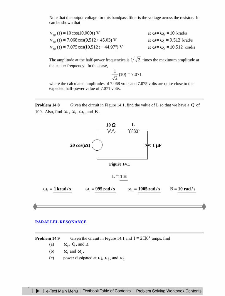
Note that the output voltage for this bandpass filter is the voltage across the resistor. Itcan be shown that
V)t000,10cos(10)t(vout = at 100 =ω=ω krad/s
V)03.45512,9cos(068.7)t(vout += at 512.91 =ω=ω krad/s
V)97.44t512,10cos(075.7)t(vout °−= at 512.102 =ω=ω krad/s
The amplitude at the half-power frequencies is 21 times the maximum amplitude atthe center frequency. In this case,
071.7)10(2
1=
where the calculated amplitudes of 7.068 volts and 7.075 volts are quite close to theexpected half-power value of 7.071 volts.
Problem 14.8 Given the circuit in Figure 14.1, find the value of L so that we have a Q of
100. Also, find 0ω , 1ω , 2ω , and B .
Figure 14.1
=L H1
=ω0 s/krad1 =ω1 s/rad995 =ω2 s/rad1005 =B s/rad10
PARALLEL RESONANCE
Problem 14.9 Given the circuit in Figure 14.1 and °∠= 02I amps, find(a) 0ω , Q , and B,
(b) 1ω and 2ω ,
(c) power dissipated at 0ω , 1ω , and 2ω .
+−20 cos(ωωωωt)
10 ΩΩΩΩ L
1 µµµµF
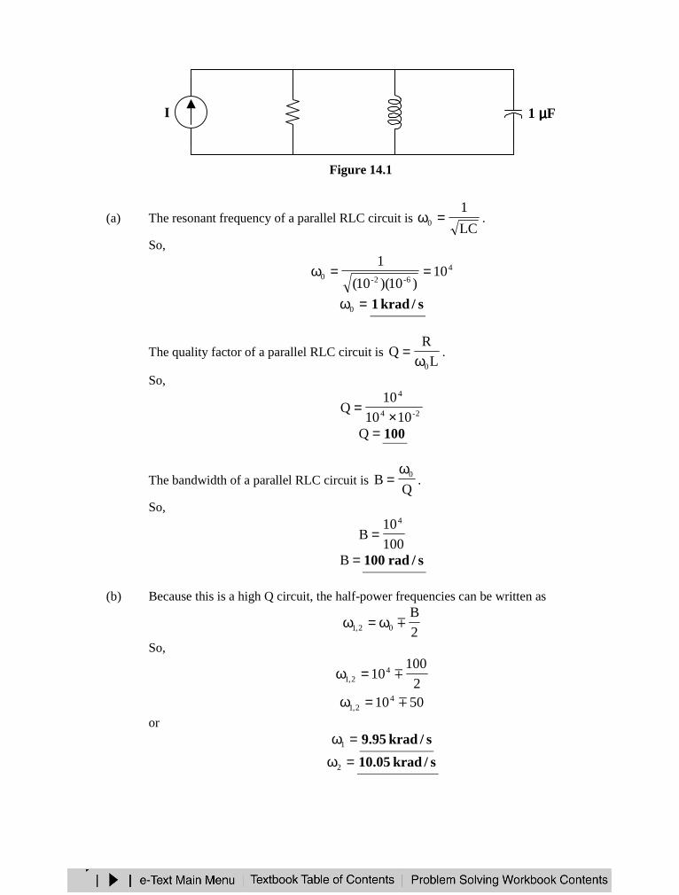
Figure 14.1
(a) The resonant frequency of a parallel RLC circuit is LC
10 =ω .
So,
4
6-2-0 10)10)(10(
1==ω
=ω0 s/krad1
The quality factor of a parallel RLC circuit is L
RQ
0ω= .
So,
2-4
4
1010
10Q
×=
=Q 100
The bandwidth of a parallel RLC circuit is Q
B 0ω= .
So,
100
10B
4
=
=B s/rad100
(b) Because this is a high Q circuit, the half-power frequencies can be written as
2
B02,1 ω=ω
So,
2
100104
2,1 =ω
501042,1 =ω
or=ω1 s/krad95.9
=ω2 s/krad05.10
I 10 kΩΩΩΩ 10 mH 1 µµµµF
+
V
−−−−
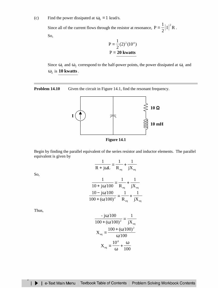
(c) Find the power dissipated at 10 =ω krad/s.
Since all of the current flows through the resistor at resonance, RI2
1P
2= .
So,
)10()2(2
1P 42=
=P kwatts20
Since 1ω and 2ω correspond to the half-power points, the power dissipated at 1ω and
2ω is kwatts10 .
Problem 14.10 Given the circuit in Figure 14.1, find the resonant frequency.
Figure 14.1
Begin by finding the parallel equivalent of the series resistor and inductor elements. The parallelequivalent is given by
eqeq jX
1
R
1
LjR
1+=
ω+So,
eqeq jX
1
R
1
100j10
1+=
ω+
eqeq2 jX
1
R
1
)100(100
100j10+=
ω+ω−
Thus,
eq2 jX
1
)100(100
100j-=
ω+ω
100
)100(100X
2
eq ωω+
=
100
10X
4
eq
ω+
ω=
I
10 ΩΩΩΩ
10 mH
1 µµµµF

At resonance,
0ω=ω and Ceq XX =
where ω
=ω
=ω
=6
6-C
10
10
1
C
1X
Thus,0
60
0
4 10
100
10
ω=
ω+
ωor
6204 10
10010 =
ω+
76820 109.91010 ×=−=ω
=ω0 s/krad95.9
or≅ω 0 s/krad10
PASSIVE FILTERS
Problem 14.11 What type of filter is represented by the circuit in Figure 14.1? What is thecutoff frequency, or what are the corner frequencies?
Figure 14.1
In the frequency domain, the circuit is
10 kΩΩΩΩ
+
vout
−−−−
+−vin 10 µµµµF
10 kΩΩΩΩ
10 kΩΩΩΩ
+
Vout
−−−−
+−Vin –j105/ωωωω ΩΩΩΩ
10 kΩΩΩΩ
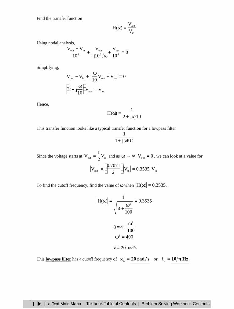
Find the transfer function
in
out
V
V)(H =ω
Using nodal analysis,
010
V
10j-
V
10
VV4
out5
out4
inout =+ω
+−
Simplifying,
0VV10
jVV outoutinout =+ω
+−
inout VV10
j2 =
ω
+
Hence,
10j2
1)(H
ω+=ω
This transfer function looks like a typical transfer function for a lowpass filter
RCj1
1
ω+
Since the voltage starts at inout V2
1V = and as ∞→ω 0Vout = , we can look at a value for
ininout V3535.0V2
7071.0V =
=
To find the cutoff frequency, find the value of ω when 3535.0)(H =ω .
3535.0
1004
1)(H
2=
ω+
=ω
10048
2ω+=
4002 =ω
20=ω rad/s
This lowpass filter has a cutoff frequency of =ωC s/rad20 or =Cf Hz10 ππππ .
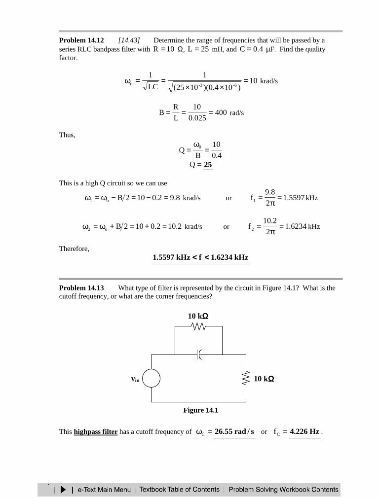
Problem 14.12 [14.43] Determine the range of frequencies that will be passed by aseries RLC bandpass filter with 10R = Ω, 25L = mH, and 4.0C = µF. Find the qualityfactor.
10)104.0)(1025(
1
LC
16-3-o =
××==ω krad/s
400025.0
10
L
RB === rad/s
Thus,
4.0
10
BQ 0 =
ω=
=Q 25
This is a high Q circuit so we can use
8.92.0102Bo1 =−=−ω=ω krad/s or 5597.12
8.9f1 =
π= kHz
2.102.0102Bo2 =+=+ω=ω krad/s or 6234.12
2.10f2 =
π= kHz
Therefore,kHz6234.1fkHz5597.1 <<<<<<<<
Problem 14.13 What type of filter is represented by the circuit in Figure 14.1? What is thecutoff frequency, or what are the corner frequencies?
Figure 14.1
This highpass filter has a cutoff frequency of =ωC s/rad55.26 or =Cf Hz226.4 .
10 kΩΩΩΩ
10 kΩΩΩΩ
+
vout
−−−−
+−vin
10 µµµµF
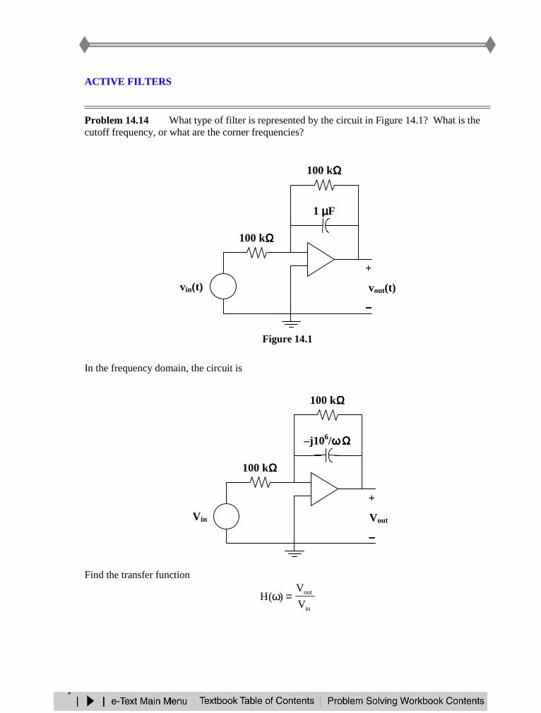
ACTIVE FILTERS
Problem 14.14 What type of filter is represented by the circuit in Figure 14.1? What is thecutoff frequency, or what are the corner frequencies?
Figure 14.1
In the frequency domain, the circuit is
Find the transfer function
in
out
V
V)(H =ω
+−vin(t)
100 kΩΩΩΩ
1 µµµµF
+
vout(t)
−−−−
−+
100 kΩΩΩΩ
+−
100 kΩΩΩΩ
+
Vout
−−−−
−+
100 kΩΩΩΩ
–j106/ωωωω ΩΩΩΩ
Vin
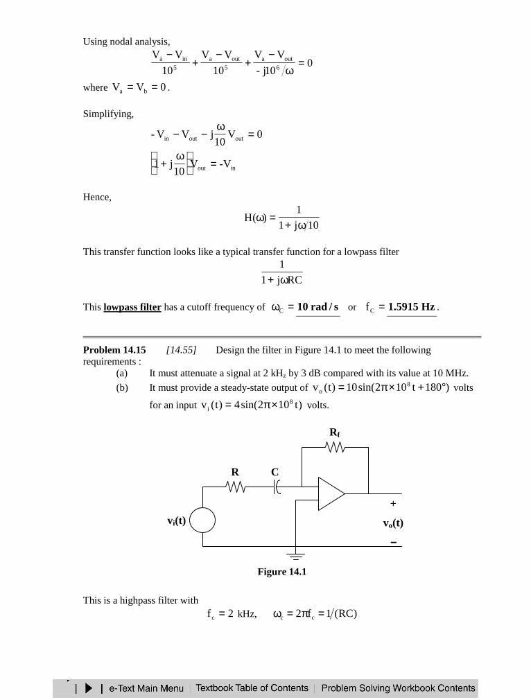
Using nodal analysis,
010j-
VV
10
VV
10
VV6
outa5
outa5
ina =ω
−+
−+
−
where 0VV ba == .
Simplifying,
0V10
jVV- outoutin =ω
−−
inout V-V10
j1 =
ω
+
Hence,
10j1
1)(H
ω+=ω
This transfer function looks like a typical transfer function for a lowpass filter
RCj1
1
ω+
This lowpass filter has a cutoff frequency of =ωC s/rad10 or =Cf Hz5915.1 .
Problem 14.15 [14.55] Design the filter in Figure 14.1 to meet the followingrequirements :
(a) It must attenuate a signal at 2 kHz by 3 dB compared with its value at 10 MHz.
(b) It must provide a steady-state output of )180t102sin(10)t(v 8o °+×π= volts
for an input )t102sin(4)t(v 8i ×π= volts.
Figure 14.1
This is a highpass filter with2fc = kHz, )RC(1f2 cc =π=ω
+−
R
+
vo(t)
−−−−
−+
Rf
C
vi(t)

or
3c 104
1f2
1RC
×π=
π=
Clearly, the capacitor becomes a short circuit at high frequencies. Hence, the high frequency gainis
4
10-
R
R- f = or R5.2Rf =
If we let =R ΩΩΩΩk10 , then =fR ΩΩΩΩk25 , and =×π
= 4104000
1C nF958.7 .
SCALING
Problem 14.16 [14.63] For the circuit in Figure 14.1,
(a) draw the new circuit after it has been scaled by 200Km = and .10K 4f =
(b) obtain the Thevenin equivalent impedance at terminals a-b of the scaled circuit at410=ω rad/s.
Figure 14.1
(a) 400)2)(200(RKR m ===′ Ω
2010
)1)(200(
K
LKL 4
f
m ===′ mH
25.0)10)(200(
5.0
KK
CC 4
fm
===′ µF
0.5 F
Ix
2 ΩΩΩΩ 0.5 Ix
a
b
1 H
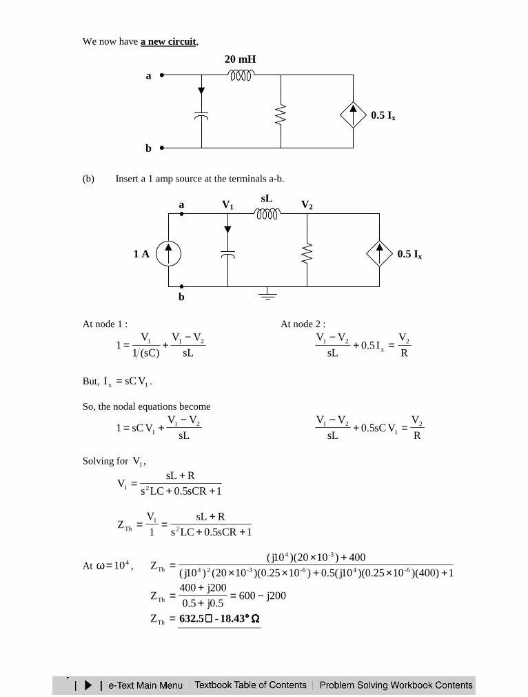
We now have a new circuit,
(b) Insert a 1 amp source at the terminals a-b.
At node 1 : At node 2 :
sL
VV
)sC(1
V1 211 −
+=R
VI5.0
sL
VV 2x
21 =+−
But, 1x VsCI = .
So, the nodal equations become
sL
VVVsC1 21
1
−+=
R
VVsC5.0
sL
VV 21
21 =+−
Solving for 1V ,
1sCR5.0LCs
RsLV 21 ++
+=
1sCR5.0LCs
RsL
1
VZ 2
1Th ++
+==
At 410=ω , 1)400)(1025.0)(10j(5.0)1025.0)(1020()10j(
400)1020)(10j(Z 6-46-3-24
3-4
Th +×+××+×
=
200j6005.0j5.0
200j400ZTh −=
++
=
=ThZ ΩΩΩΩ°°°°∠∠∠∠ 43.18-5.632
0.25 µµµµF
Ix
400 ΩΩΩΩ 0.5 Ix
a
b
20 mH
1 A 1/(sC)
Ix
R 0.5 Ix
a
b
V1 V2sL
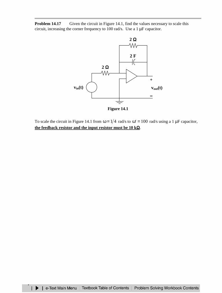
Problem 14.17 Given the circuit in Figure 14.1, find the values necessary to scale thiscircuit, increasing the corner frequency to 100 rad/s. Use a 1 µF capacitor.
Figure 14.1
To scale the circuit in Figure 14.1 from 41=ω rad/s to 100=ω′ rad/s using a 1 µF capacitor,
the feedback resistor and the input resistor must be 10 kΩΩΩΩ.
+−vin(t)
2 ΩΩΩΩ
2 F
+
vout(t)
−−−−
−+
2 ΩΩΩΩ