Signal Propagation - SRM Institute of Science and … Isotropic Signal Propagation • In free...
39
Signal Propagation Jie Gao 01/27/2010
Transcript of Signal Propagation - SRM Institute of Science and … Isotropic Signal Propagation • In free...

Signal Propagation
Jie Gao
01/27/2010

Signal
• Signal are generated as physical representations of data
• A signal is a function of time and location
1ideal
digital signal
2
1
0
t
a special type of signal, sine waves, also called harmonics: s(t) = A sin(2π f t + ϕ)
with frequency f, period T=1/f, amplitude A, phase shift ϕ
0
digital signal
t
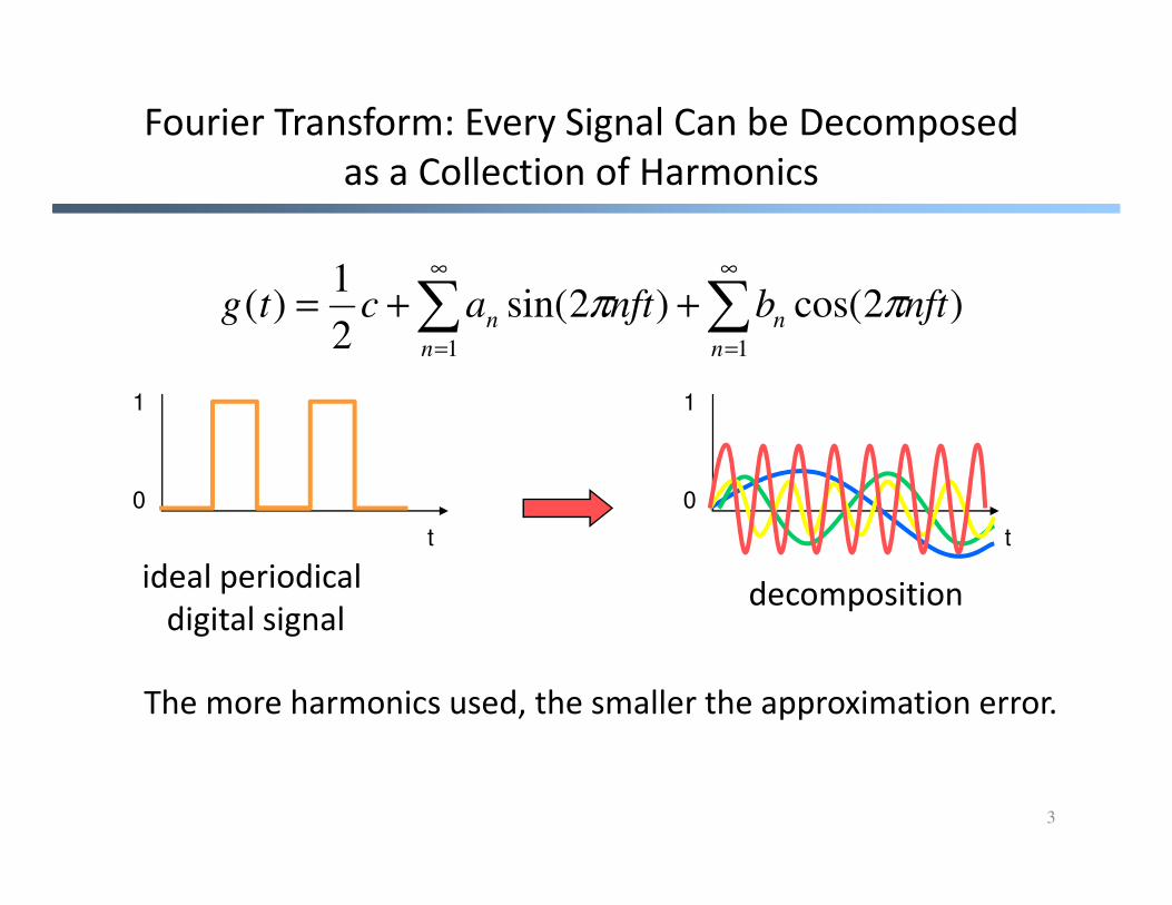
Fourier Transform: Every Signal Can be Decomposed
as a Collection of Harmonics
)2cos()2sin(2
1)(
11
nftbnftactgn
n
n
n ππ ∑∑∞
=
∞
=
++=
1 1
3
0 0
t t
ideal periodical
digital signaldecomposition
The more harmonics used, the smaller the approximation error.

4
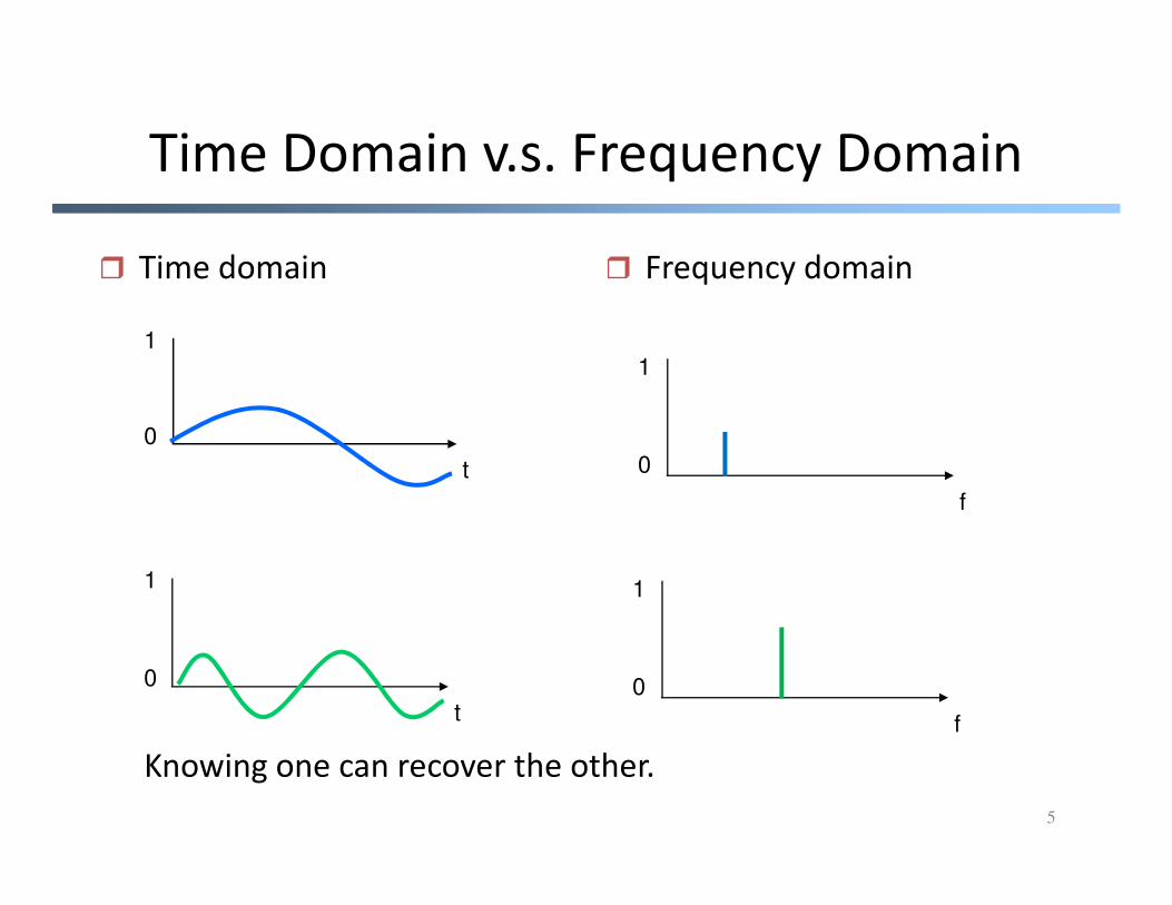
Time Domain v.s. Frequency Domain
� Time domain � Frequency domain
1
0
1
0
5
0
f
t
1
0
t
1
0
f
Knowing one can recover the other.

Interference
� Signals add up1
0
t
1
0
t
6
� Apply Fourier transform
t t
1
0
ff 2f
1
0t
1
0t
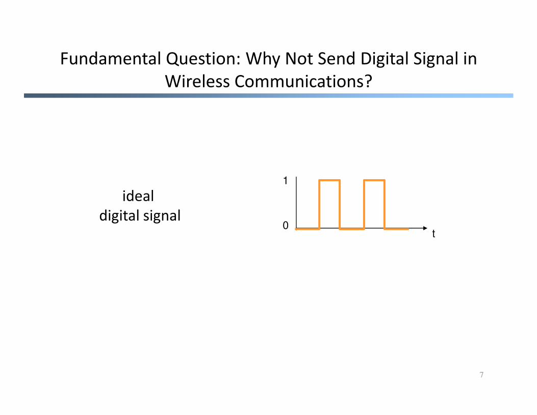
Fundamental Question: Why Not Send Digital Signal in
Wireless Communications?
1
ideal
digital signal
7
0digital signal
t

Fundamental Question: Why Not Send Digital Signal in
Wireless Communications?
• May cause interference
– suppose digital frame length T, then signal
decomposes into frequencies at 1/T, 2/T, 3/T, …
– let T = 1 ms, generates radio waves at frequencies – let T = 1 ms, generates radio waves at frequencies
of 1 KHz, 2 KHz, 3 KHz, …
8
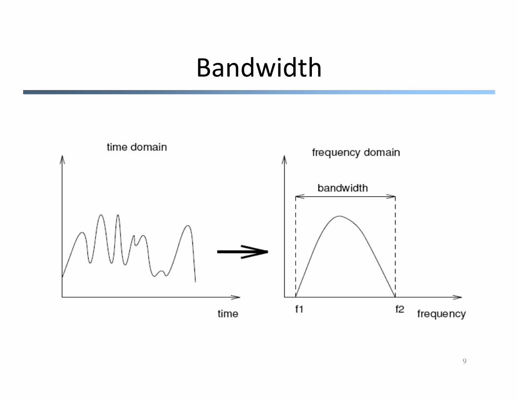
Bandwidth
9

Frequencies for Communications
1 Mm300 Hz
10 km30 kHz
100 m3 MHz
1 m300 MHz
10 mm30 GHz
100 µm3 THz
1 µm300 THz
visible lightVLF LF MF HF VHF UHF SHF EHF infrared UV
optical transmissioncoax cabletwisted pair
10
VLF = Very Low Frequency UHF = Ultra High Frequency
LF = Low Frequency SHF = Super High Frequency
MF = Medium Frequency EHF = Extra High Frequency
HF = High Frequency UV = Ultraviolet Light
VHF = Very High Frequency
Frequency and wave length:
λ = c/f
wave length λ, speed of light c ≅ 3x10⁸m/s, frequency f
visible lightVLF LF MF HF VHF UHF SHF EHF infrared UV

Spectrum
11

Frequencies and Regulations
� ITU-R holds auctions for new frequencies, manages frequency bands
worldwide (WRC, World Radio Conferences)
Europe USA Japan
CellularPhones
GSM 450 - 457, 479 -486/460 - 467,489 -496, 890 - 915/935 -960,1710 - 1785/1805 -1880
AMPS , TDMA , CDMA824- 849, 869-894TDMA , CDMA , GSM1850 - 1910,1930 - 1990
PDC810- 826, 940-956,1429 - 1465, 1477 - 1513
12
1880UMTS (FDD) 1920 -1980, 2110 - 2190UMTS (TDD) 1900 -1920, 2020 - 2025
1930 - 1990
CordlessPhones
CT1+ 885 - 887, 930 -932CT2864-868DECT 1880 - 1900
PACS 1850 - 1910, 1930 -1990PACS -UB 1910 - 1930
PHS1895 - 1918JCT254-380
Wireless LANs
IEEE 802.112400 - 2483HIPERLAN 25150 - 5350, 5470 -5725
902-928I EEE 802.112400 - 24835150 - 5350, 5725 - 5825
IEEE 802.112471 - 24975150 - 5250
Others RF- Control27, 128, 418, 433,
868
RF- Control315, 915
RF- Control426, 868

Antennas and Signal Propagation
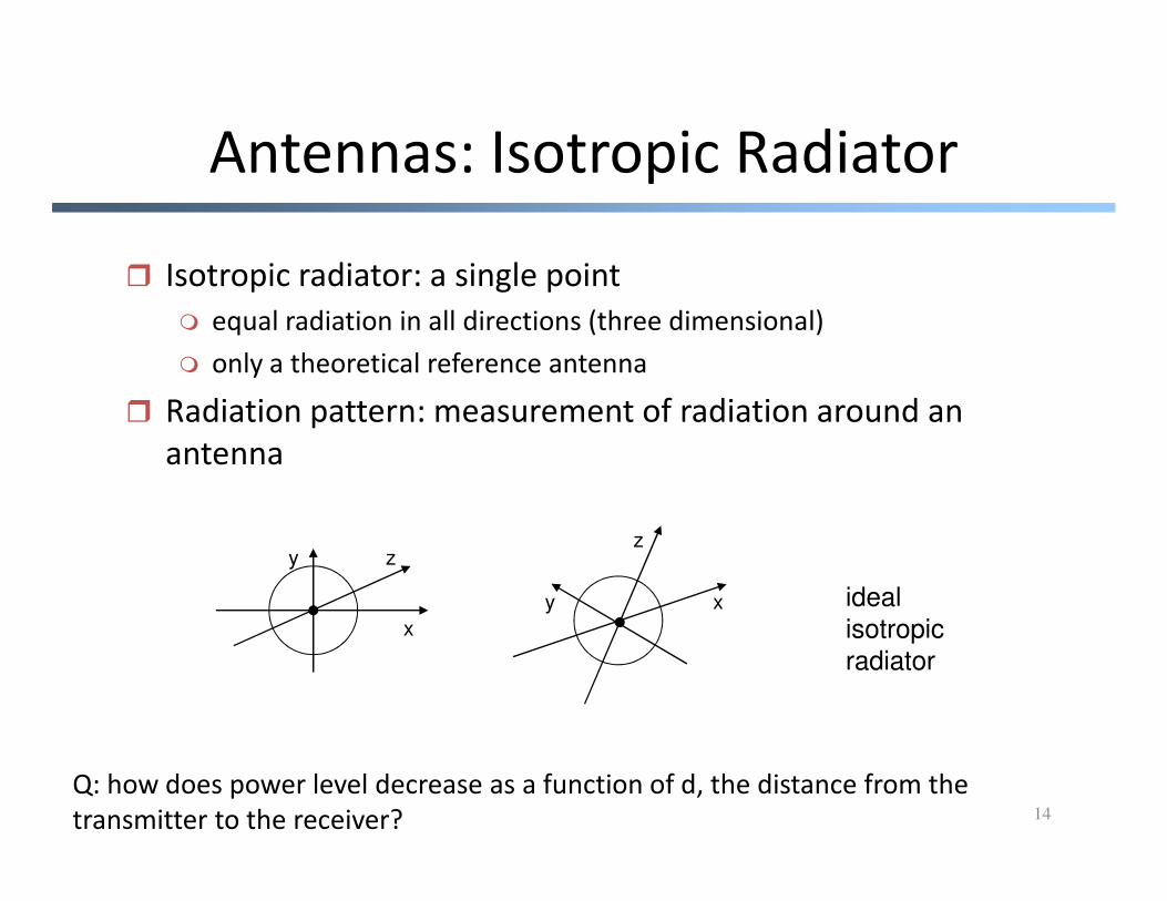
Antennas: Isotropic Radiator
� Isotropic radiator: a single point
� equal radiation in all directions (three dimensional)
� only a theoretical reference antenna
� Radiation pattern: measurement of radiation around an
antenna
14
antenna
zy
x
z
y x ideal
isotropic
radiator
Q: how does power level decrease as a function of d, the distance from the
transmitter to the receiver?

Real Antennas
• Real antennas are not isotropic radiators
• Some simple antennas: quarter wave λ/4 on car roofs or half
wave dipole λ/2
� size of antenna proportional to wavelength for better
transmission/receivingtransmission/receiving
15
λ/4λ/2
Q: Assume frequency 1 Ghz, λ = ?

Dipole: Radiation Pattern of a Dipole
16
http://www.tpub.com/content/neets/14182/index.htm
http://en.wikipedia.org/wiki/Dipole_antenna

Why Not Digital Signal (revisited)
• Not good for spectrum usage/sharing
• The wavelength can be extremely large to
build portable devices
– e.g., T = 1 us -> f=1/T = 1MHz -> wavelength = – e.g., T = 1 us -> f=1/T = 1MHz -> wavelength =
3x10⁸/106 = 300m
17

Free-Space Isotropic Signal Propagation
• In free space, receiving power proportional to 1/d² (d = distance between transmitter and receiver)
2
4
=
dGG
P
Ptr
t
r
π
λ
� P : received power• The total radiation power
remains constant, but the surface area of a sphere with radius r increases like r2.
18
� Pr: received power
� Pt: transmitted power
� Gr, Gt: receiver and
transmitter antenna gain
� λ (=c/f): wave length
Sometime we write path loss in log scale:
Lp = 10 log(Pt) – 10log(Pr)

Signal Propagation
� Receiving power additionally influenced by
� shadowing (e.g. through a wall or a door)
� refraction depending on the density of a medium
� reflection at large obstacles
� scattering at small obstacles
19
� scattering at small obstacles
� diffraction at edges
reflection
scattering
diffraction
shadow fadingrefraction

Signal Propagation: Scenarios
Details of signal
propagation are very
complicated
We want to understand
20
We want to understand
the key characteristics
that are important to
our objective

Reason I: Shadowing
• Signal strength loss after passing through obstacles
• Some sample numbers
21
i.e. reduces to ¼ of signal
10 log(1/4) = -6.02
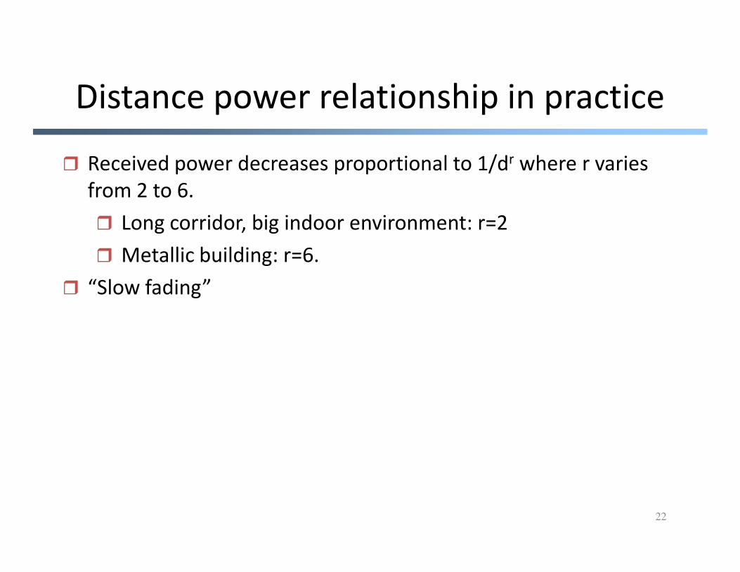
Distance power relationship in practice
� Received power decreases proportional to 1/dr where r varies
from 2 to 6.
� Long corridor, big indoor environment: r=2
� Metallic building: r=6.
� “Slow fading”
22
� “Slow fading”
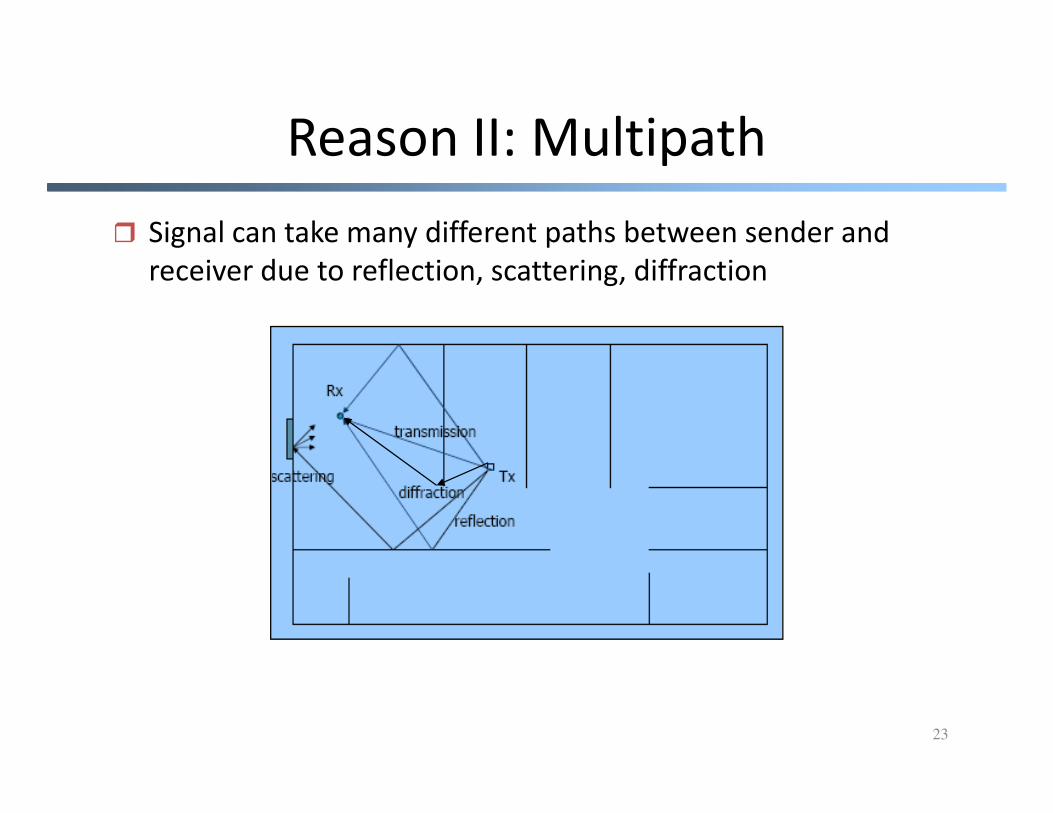
Reason II: Multipath
� Signal can take many different paths between sender and
receiver due to reflection, scattering, diffraction
23
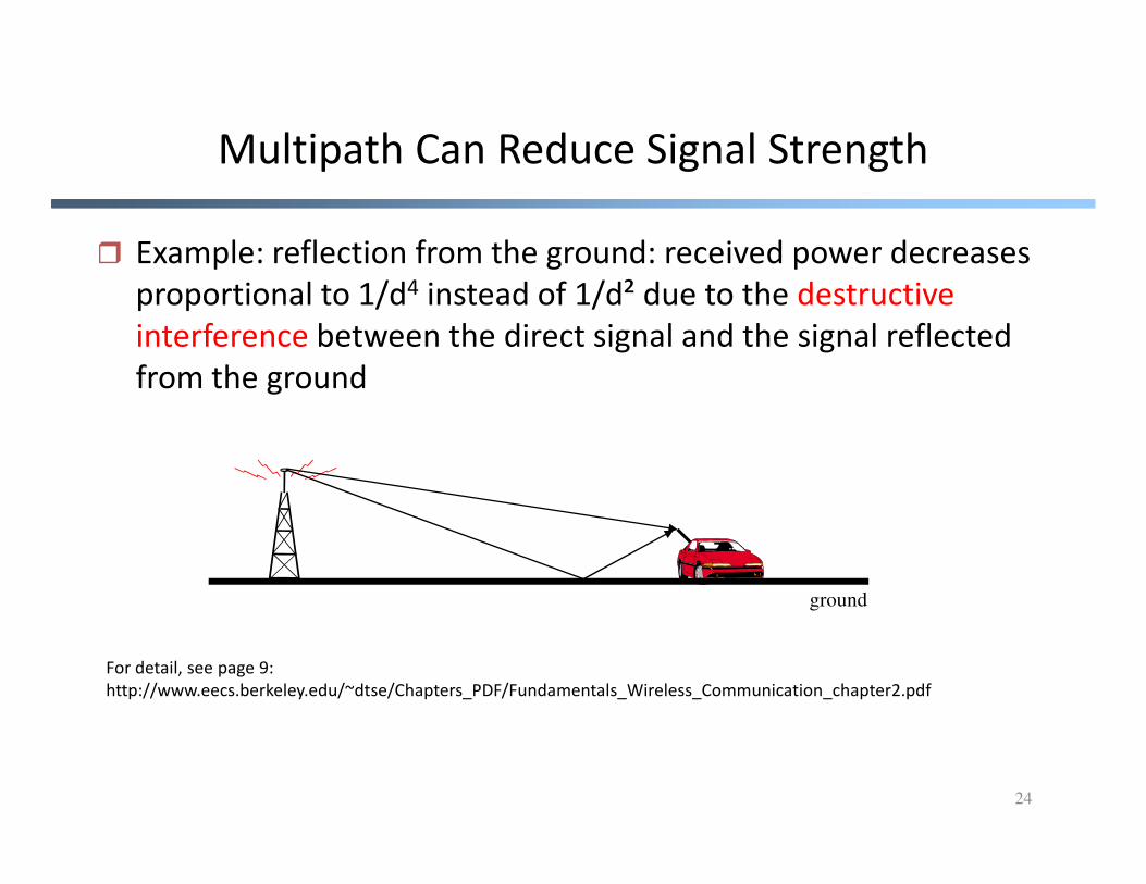
Multipath Can Reduce Signal Strength
� Example: reflection from the ground: received power decreases
proportional to 1/d4 instead of 1/d² due to the destructive
interference between the direct signal and the signal reflected
from the ground
24
ground
For detail, see page 9:
http://www.eecs.berkeley.edu/~dtse/Chapters_PDF/Fundamentals_Wireless_Communication_chapter2.pdf

Multipath Fading
25
� Due to constructive and destructive interference of
multiple transmitted waves, signal strength may vary
widely as a function of receiver position
� Listen to radio on a car.

Multipath Effect
(fixed receiver location)
� Channel characteristics change over location,
frequencyexample
26
d1d2
( )1
11 ][2cos
d
tfc
d−πα
( )ftπ2cos
πλ
πππππ +−
=+−
=+− 2121 22)(2 21dd
c
ddfff
c
d
c
d
( )2
22 ][2cos
d
tfc
d−
−πα
phase
difference:

Multipath
(fixed receiver location)
• Suppose at d1-d2 the two waves totally
destruct. (what does it mean?)
integer2121 =−
=−
λ
dd
c
ddf
• Q: can we find places where the two waves
construct?
27
λc
πλ
πππ +−
=+− 2121 22
dd
c
ddf

Option 1: Change Location
• If receiver moves to the right by λ/4:
d1’ = d1 + λ/4;
d2’ = d2 - λ/4;
-> πλ
π +− 21 ''
2dd->
28
ππλ
π
πλ
λλπ
λπ
πλ
π
++−
=
+−−
+−
=
+
21
21
2
)4/(4/22
2
dd
dd
By moving a quarter of wavelength, destructive
turns into constructive.

Option 2: Change Frequency
212
1'
dd
cff
−±=
� Change frequency:
29
� The change depends on delay spread
πλ
πππ +−
=+− 2121 22
dd
c
ddf

Multipath Fading: A Simple Two-path
Example
d2
30
d1 receiver
- Wavelength is about 0.3 m for 1 GHz cellular
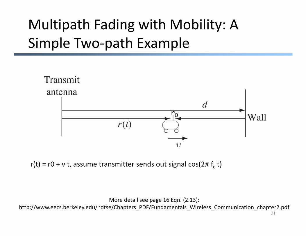
Multipath Fading with Mobility: A
Simple Two-path Example
r0
31
r(t) = r0 + v t, assume transmitter sends out signal cos(2π fc t)
More detail see page 16 Eqn. (2.13):
http://www.eecs.berkeley.edu/~dtse/Chapters_PDF/Fundamentals_Wireless_Communication_chapter2.pdf

Multipath Effect
(moving receiver)
� Channel characteristics change over time (location)
example
d
32
d1d2
( )1
11 ][2cos
d
tfc
d−πα
( )ftπ2cos
( )2
22 ][2cos
d
tfc
d−
−πα
Suppose d1=r0+vt
d2=2d-r0-vtd1≈d2
d

Derivation
])[2sin(])[2sin(2
)sin()sin(2
])[2cos(])[2cos(
0000
020020
00
)2(2
2
][2][2
2
][2][2
2
vtrdvtrvtrdvtr
tftftftf
c
vtrd
c
vtr
ftf
tftf
c
vtrd
c
vtr
c
vtrd
c
vtr
−−+−−−−++
−−−−+−
−−+
−−=
−=
−−−−−+−−+
ππππ
ππ
ππ
33
])[sin(])[2sin(2
])[2sin(])[2sin(2
])[2sin(])[2sin(2
])[2sin(])[2sin(2
0
0
0
0000
2
2
)2(
2
2
cv
rd
c
vf
cd
c
dvtr
cd
c
dvtr
cd
c
vtrdvtr
c
vtrdvtr
ttf
ftf
ftf
ftf
−
−+
−+
−−+−−−−++
−−=
−=
−−−=
−−=
ππ
ππ
ππ
ππ
See http://www.sosmath.com/trig/Trig5/trig5/trig5.html for cos(u)-cos(v)
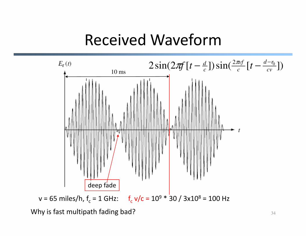
Received Waveform
10 ms])[sin(])[2sin(2 02
cv
rd
c
vf
cd ttf
−−− ππ
34
v = 65 miles/h, fc = 1 GHz: fc v/c = 109 * 30 / 3x108 = 100 Hz
Why is fast multipath fading bad?
deep fade

Small-Scale Fading
35
signal at sender
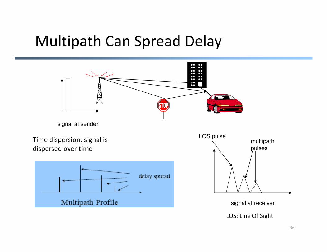
Multipath Can Spread Delay
36
signal at sender
signal at receiver
LOS pulsemultipathpulses
LOS: Line Of Sight
Time dispersion: signal is
dispersed over time

Delay Spread RMS: root-mean-square
37
signal at sender
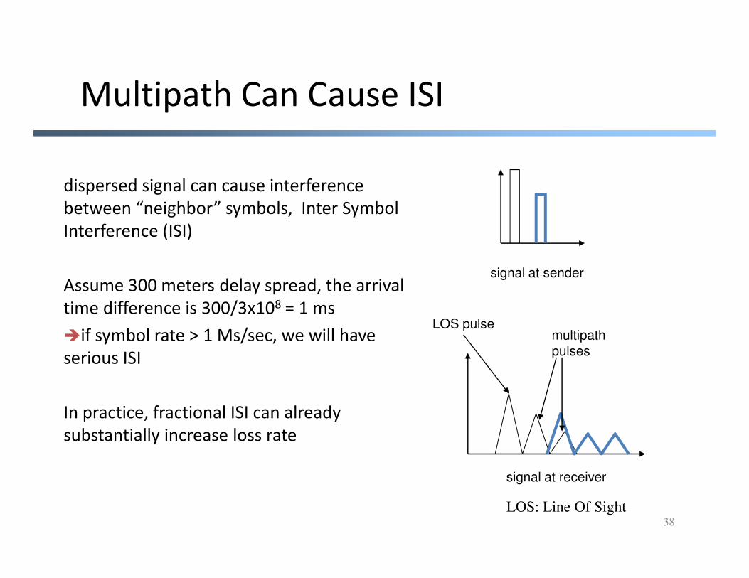
Multipath Can Cause ISI
dispersed signal can cause interference
between “neighbor” symbols, Inter Symbol
Interference (ISI)
Assume 300 meters delay spread, the arrival
38
signal at receiver
LOS pulsemultipathpulses
LOS: Line Of Sight
Assume 300 meters delay spread, the arrival
time difference is 300/3x108 = 1 ms
�if symbol rate > 1 Ms/sec, we will have
serious ISI
In practice, fractional ISI can already
substantially increase loss rate

Summary: Wireless Channels
� Channel characteristics change over location, time, and
frequency
Large-scalefading
power
path loss
Received Signal Power (dB)
39
small-scale fadingtimelog (distance)
frequency