
Sigma-7-Series AC Servo Drive Direct Drive Servomotor Product … · 2016-06-08 · iii About this...
88
Model: SGMCS/SGMCV Direct Drive Servomotor Σ -7-Series AC Servo Drive Product Manual MANUAL NO. SIEP S800001 38A 1 2 3 4 5 6 7 8 Basic Information on Servomotors Capacity Selection Servomotor Installation Maintenance and Inspection Appendix Specifications, Ratings, and External Dimensions of SGMCS Servomotors Specifications, Ratings, and External Dimensions of SGMCV Servomotors Connections between Servomotors and SERVOPACKs
Transcript of Sigma-7-Series AC Servo Drive Direct Drive Servomotor Product … · 2016-06-08 · iii About this...
Model: SGMCS/SGMCV
Direct Drive ServomotorΣ-7-Series AC Servo Drive
Product Manual
MANUAL NO. SIEP S800001 38A
1
2
3
4
5
6
7
8
Basic Information on Servomotors
Capacity Selection
Servomotor Installation
Maintenance and Inspection
Appendix
Specifications, Ratings, andExternal Dimensions of SGMCS Servomotors
Specifications, Ratings, andExternal Dimensions of SGMCV Servomotors
Connections between Servomotors and SERVOPACKs
Copyright © 2014 YASKAWA ELECTRIC CORPORATION
All rights reserved. No part of this publication may be reproduced, stored in a retrieval system, or transmitted, in any form, or by any means, mechanical, elec-tronic, photocopying, recording, or otherwise, without the prior written permission of Yaskawa. No patent liability is assumed with respect to the use of the informa-tion contained herein. Moreover, because Yaskawa is constantly striving to improve its high-quality products, the information contained in this manual is sub-ject to change without notice. Every precaution has been taken in the preparation of this manual. Nevertheless, Yaskawa assumes no responsibility for errors or omissions. Neither is any liability assumed for damages resulting from the use of the information contained in this publication.
iii
About this Manual
This manual provides information required to select, install, connect, and maintain Direct Drive Ser-vomotors for Σ-7-Series AC Servo Drives.Read and understand this manual to ensure correct usage of the Σ-7-Series AC Servo Drives.
Keep this manual in a safe place so that it can be referred to whenever necessary.
Outline of Manual
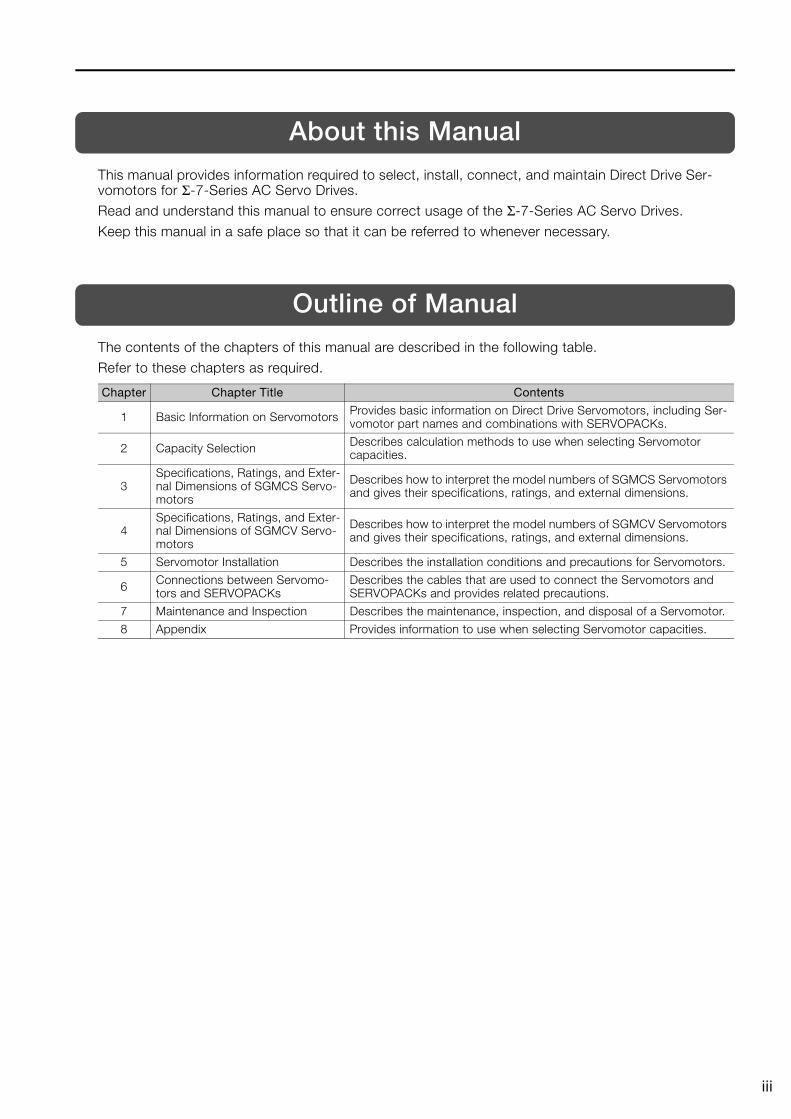
The contents of the chapters of this manual are described in the following table.Refer to these chapters as required.
Chapter Chapter Title Contents
1 Basic Information on Servomotors Provides basic information on Direct Drive Servomotors, including Ser-vomotor part names and combinations with SERVOPACKs.
2 Capacity Selection Describes calculation methods to use when selecting Servomotor capacities.
3Specifications, Ratings, and Exter-nal Dimensions of SGMCS Servo-motors
Describes how to interpret the model numbers of SGMCS Servomotors and gives their specifications, ratings, and external dimensions.
4Specifications, Ratings, and Exter-nal Dimensions of SGMCV Servo-motors
Describes how to interpret the model numbers of SGMCV Servomotors and gives their specifications, ratings, and external dimensions.
5 Servomotor Installation Describes the installation conditions and precautions for Servomotors.
6 Connections between Servomo-tors and SERVOPACKs
Describes the cables that are used to connect the Servomotors and SERVOPACKs and provides related precautions.
7 Maintenance and Inspection Describes the maintenance, inspection, and disposal of a Servomotor.
8 Appendix Provides information to use when selecting Servomotor capacities.
iv
Related Documents
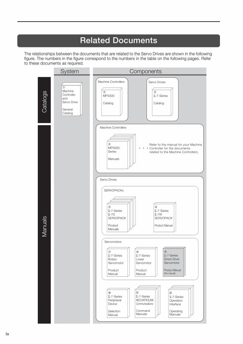
The relationships between the documents that are related to the Servo Drives are shown in the following figure. The numbers in the figure correspond to the numbers in the table on the following pages. Refer to these documents as required.
Machine Controllers
Refer to the manual for your Machine Controller for the documents related to the Machine Controllers.
SERVOPACKs
Servo Drives
Servomotors
� Σ-7-SeriesRotary Servomotor
Product Manual
� Σ-7-SeriesLinear Servomotor
Product Manual
� Σ-7-Series Peripheral Device
Selection Manual
� Σ-7-Series Σ-7W SERVOPACK
Product Manual
� Σ-7-Series Σ-7S SERVOPACK
Product Manuals
Σ-7-Series MECHATROLINK Communications
Command Manuals
Σ-7-Series Operation Interface
Operating Manuals
� MP3000-Series
Manuals
System Components
� Machine Controller and Servo Drive
General Catalog
MP3300
Catalog
Σ-7-Series
Catalog
Machine Controllers Servo Drives
Man
uals
Cat
alog
s
� Σ-7-SeriesDirect Drive Servomotor
Product Manual (this manual)
v
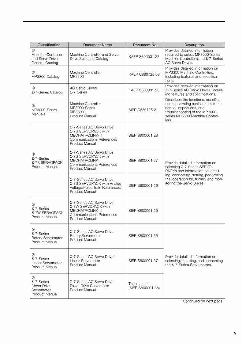
Classification Document Name Document No. Description
Machine Controller and Servo DriveGeneral Catalog
Machine Controller and Servo Drive Solutions Catalog KAEP S800001 22
Provides detailed information required to select MP3000-Series Machine Controllers and Σ-7-Series AC Servo Drives.
MP3300 CatalogMachine ControllerMP3300 KAEP C880725 03
Provides detailed information on MP3300 Machine Controllers, including features and specifica-tions.
Σ-7-Series CatalogAC Servo DrivesΣ-7 Series KAEP S800001 23
Provides detailed information on Σ-7-Series AC Servo Drives, includ-ing features and specifications.
MP3000-Series Manuals
Machine Controller MP3000 SeriesMP3300Product Manual
SIEP C880725 21
Describes the functions, specifica-tions, operating methods, mainte-nance, inspections, and troubleshooting of the MP3000-series MP3300 Machine Control-lers.
Σ-7-Series Σ-7S SERVOPACK Product Manuals
Σ-7-Series AC Servo Drive Σ-7S SERVOPACK with MECHATROLINK-III Communications References Product Manual
SIEP S800001 28
Provide detailed information on selecting Σ-7-Series SERVO-PACKs and information on install-ing, connecting, setting, performing trial operation for, tuning, and mon-itoring the Servo Drives.
Σ-7-Series AC Servo Drive Σ-7S SERVOPACK with MECHATROLINK-II Communications References Product Manual
SIEP S800001 27
Σ-7-Series AC Servo Drive Σ-7S SERVOPACK with Analog Voltage/Pulse Train References Product Manual
SIEP S800001 26
Σ-7-Series Σ-7W SERVOPACK Product Manual
Σ-7-Series AC Servo Drive Σ-7W SERVOPACK with MECHATROLINK-III Communications References Product Manual
SIEP S800001 29
Σ-7-Series Rotary Servomotor Product Manual
Σ-7-Series AC Servo Drive Rotary Servomotor Product Manual
SIEP S800001 36
Provide detailed information on selecting, installing, and connecting the Σ-7-Series Servomotors.
Σ-7-Series Linear Servomotor Product Manual
Σ-7-Series AC Servo Drive Linear Servomotor Product Manual
SIEP S800001 37
Σ-7-Series Direct Drive Servomotor Product Manual
Σ-7-Series AC Servo Drive Direct Drive Servomotor Product Manual
This manual (SIEP S800001 38)
Continued on next page.
vi
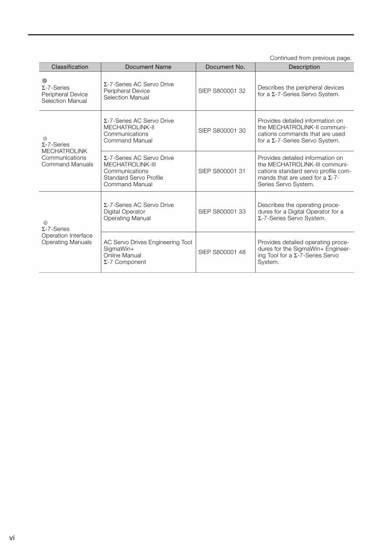
Σ-7-Series Peripheral Device Selection Manual
Σ-7-Series AC Servo Drive Peripheral Device Selection Manual
SIEP S800001 32 Describes the peripheral devices for a Σ-7-Series Servo System.
Σ-7-Series MECHATROLINK Communications Command Manuals
Σ-7-Series AC Servo Drive MECHATROLINK-II Communications Command Manual
SIEP S800001 30
Provides detailed information on the MECHATROLINK-II communi-cations commands that are used for a Σ-7-Series Servo System.
Σ-7-Series AC Servo Drive MECHATROLINK-III Communications Standard Servo Profile Command Manual
SIEP S800001 31
Provides detailed information on the MECHATROLINK-III communi-cations standard servo profile com-mands that are used for a Σ-7-Series Servo System.
Σ-7-Series Operation Interface Operating Manuals
Σ-7-Series AC Servo Drive Digital Operator Operating Manual
SIEP S800001 33Describes the operating proce-dures for a Digital Operator for a Σ-7-Series Servo System.
AC Servo Drives Engineering Tool SigmaWin+ Online Manual Σ-7 Component
SIEP S800001 48
Provides detailed operating proce-dures for the SigmaWin+ Engineer-ing Tool for a Σ-7-Series Servo System.
Continued from previous page.
Classification Document Name Document No. Description
vii
Using This Manual
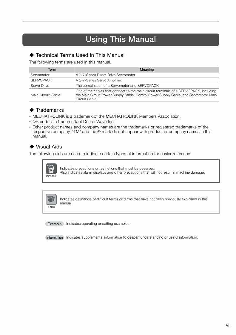
Technical Terms Used in This ManualThe following terms are used in this manual.
Trademarks• MECHATROLINK is a trademark of the MECHATROLINK Members Association.• QR code is a trademark of Denso Wave Inc.• Other product names and company names are the trademarks or registered trademarks of the
respective company. “TM” and the ® mark do not appear with product or company names in this manual.
Visual AidsThe following aids are used to indicate certain types of information for easier reference.
Term Meaning
Servomotor A Σ-7-Series Direct Drive Servomotor.
SERVOPACK A Σ-7-Series Servo Amplifier.
Servo Drive The combination of a Servomotor and SERVOPACK.
Main Circuit CableOne of the cables that connect to the main circuit terminals of a SERVOPACK, including the Main Circuit Power Supply Cable, Control Power Supply Cable, and Servomotor Main Circuit Cable.
Indicates precautions or restrictions that must be observed.Also indicates alarm displays and other precautions that will not result in machine damage.
Indicates definitions of difficult terms or terms that have not been previously explained in this manual.
Indicates operating or setting examples.
Indicates supplemental information to deepen understanding or useful information.
Important
Term
Example
Information
viii
Safety Precautions
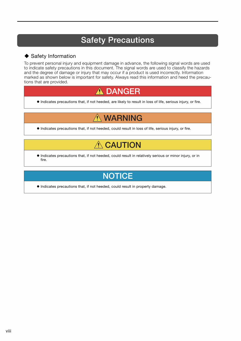
Safety InformationTo prevent personal injury and equipment damage in advance, the following signal words are used to indicate safety precautions in this document. The signal words are used to classify the hazards and the degree of damage or injury that may occur if a product is used incorrectly. Information marked as shown below is important for safety. Always read this information and heed the precau-tions that are provided.
DANGERIndicates precautions that, if not heeded, are likely to result in loss of life, serious injury, or fire.
WARNINGIndicates precautions that, if not heeded, could result in loss of life, serious injury, or fire.
CAUTION
Indicates precautions that, if not heeded, could result in relatively serious or minor injury, or in fire.
NOTICEIndicates precautions that, if not heeded, could result in property damage.
ix
Safety Precautions That Must Always Be Observed
General Precautions
Storage Precautions
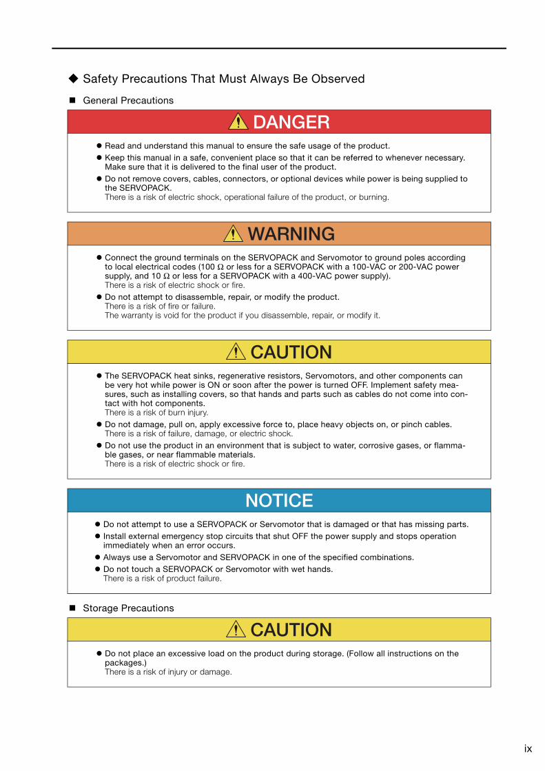
DANGERRead and understand this manual to ensure the safe usage of the product.Keep this manual in a safe, convenient place so that it can be referred to whenever necessary. Make sure that it is delivered to the final user of the product.Do not remove covers, cables, connectors, or optional devices while power is being supplied to the SERVOPACK.There is a risk of electric shock, operational failure of the product, or burning.
WARNINGConnect the ground terminals on the SERVOPACK and Servomotor to ground poles according to local electrical codes (100 Ω or less for a SERVOPACK with a 100-VAC or 200-VAC power supply, and 10 Ω or less for a SERVOPACK with a 400-VAC power supply).There is a risk of electric shock or fire.Do not attempt to disassemble, repair, or modify the product.There is a risk of fire or failure.The warranty is void for the product if you disassemble, repair, or modify it.
CAUTIONThe SERVOPACK heat sinks, regenerative resistors, Servomotors, and other components can be very hot while power is ON or soon after the power is turned OFF. Implement safety mea-sures, such as installing covers, so that hands and parts such as cables do not come into con-tact with hot components.There is a risk of burn injury.Do not damage, pull on, apply excessive force to, place heavy objects on, or pinch cables.There is a risk of failure, damage, or electric shock.Do not use the product in an environment that is subject to water, corrosive gases, or flamma-ble gases, or near flammable materials.There is a risk of electric shock or fire.
NOTICEDo not attempt to use a SERVOPACK or Servomotor that is damaged or that has missing parts.Install external emergency stop circuits that shut OFF the power supply and stops operation immediately when an error occurs.Always use a Servomotor and SERVOPACK in one of the specified combinations.Do not touch a SERVOPACK or Servomotor with wet hands.There is a risk of product failure.
CAUTIONDo not place an excessive load on the product during storage. (Follow all instructions on the packages.)There is a risk of injury or damage.
x
Transportation Precautions
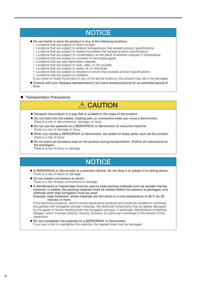
NOTICEDo not install or store the product in any of the following locations.• Locations that are subject to direct sunlight• Locations that are subject to ambient temperatures that exceed product specifications• Locations that are subject to relative humidities that exceed product specifications• Locations that are subject to condensation as the result of extreme changes in temperature• Locations that are subject to corrosive or flammable gases• Locations that are near flammable materials• Locations that are subject to dust, salts, or iron powder• Locations that are subject to water, oil, or chemicals• Locations that are subject to vibration or shock that exceeds product specifications• Locations that are subject to radiationIf you store or install the product in any of the above locations, the product may fail or be damaged.Consult with your Yaskawa representative if you have stored products for an extended period of time.
CAUTIONTransport the product in a way that is suitable to the mass of the product.Do not hold onto the cables, rotating part, or connectors when you move a Servomotor.There is a risk of disconnection, damage, or injury.Do not use the eyebolts on a SERVOPACK or Servomotor to move the machine.There is a risk of damage or injury.When you handle a SERVOPACK or Servomotor, be careful of sharp parts, such as the corners.There is a risk of injury.Do not place an excessive load on the product during transportation. (Follow all instructions on the packages.)There is a risk of injury or damage.
NOTICEA SERVOPACK or Servomotor is a precision device. Do not drop it or subject it to strong shock.There is a risk of failure or damage.Do not subject connectors to shock.There is a risk of faulty connections or damage.If disinfectants or insecticides must be used to treat packing materials such as wooden frames, plywood, or pallets, the packing materials must be treated before the product is packaged, and methods other than fumigation must be used.Example: Heat treatment, where materials are kiln-dried to a core temperature of 56°C for 30
minutes or more.If the electronic products, which include stand-alone products and products installed in machines, are packed with fumigated wooden materials, the electrical components may be greatly damaged by the gases or fumes resulting from the fumigation process. In particular, disinfectants containing halogen, which includes chlorine, fluorine, bromine, or iodine can contribute to the erosion of the capacitors.Do not overtighten the eyebolts on a SERVOPACK or Servomotor.If you use a tool to overtighten the eyebolts, the tapped holes may be damaged.
xi
Installation Precautions
Wiring Precautions
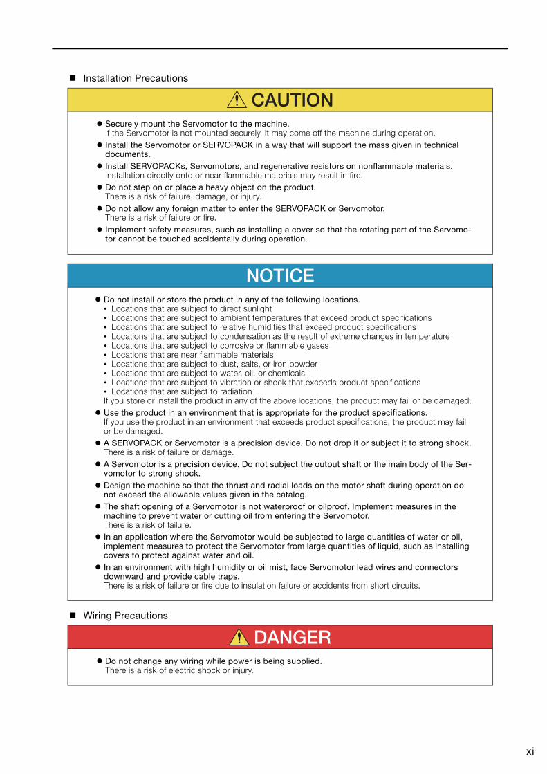
CAUTIONSecurely mount the Servomotor to the machine.If the Servomotor is not mounted securely, it may come off the machine during operation.Install the Servomotor or SERVOPACK in a way that will support the mass given in technical documents.Install SERVOPACKs, Servomotors, and regenerative resistors on nonflammable materials.Installation directly onto or near flammable materials may result in fire.Do not step on or place a heavy object on the product.There is a risk of failure, damage, or injury.Do not allow any foreign matter to enter the SERVOPACK or Servomotor.There is a risk of failure or fire.Implement safety measures, such as installing a cover so that the rotating part of the Servomo-tor cannot be touched accidentally during operation.
NOTICEDo not install or store the product in any of the following locations.• Locations that are subject to direct sunlight• Locations that are subject to ambient temperatures that exceed product specifications• Locations that are subject to relative humidities that exceed product specifications• Locations that are subject to condensation as the result of extreme changes in temperature• Locations that are subject to corrosive or flammable gases• Locations that are near flammable materials• Locations that are subject to dust, salts, or iron powder• Locations that are subject to water, oil, or chemicals• Locations that are subject to vibration or shock that exceeds product specifications• Locations that are subject to radiationIf you store or install the product in any of the above locations, the product may fail or be damaged.Use the product in an environment that is appropriate for the product specifications.If you use the product in an environment that exceeds product specifications, the product may fail or be damaged.A SERVOPACK or Servomotor is a precision device. Do not drop it or subject it to strong shock.There is a risk of failure or damage.A Servomotor is a precision device. Do not subject the output shaft or the main body of the Ser-vomotor to strong shock.Design the machine so that the thrust and radial loads on the motor shaft during operation do not exceed the allowable values given in the catalog.The shaft opening of a Servomotor is not waterproof or oilproof. Implement measures in the machine to prevent water or cutting oil from entering the Servomotor.There is a risk of failure.In an application where the Servomotor would be subjected to large quantities of water or oil, implement measures to protect the Servomotor from large quantities of liquid, such as installing covers to protect against water and oil.In an environment with high humidity or oil mist, face Servomotor lead wires and connectors downward and provide cable traps.There is a risk of failure or fire due to insulation failure or accidents from short circuits.
DANGERDo not change any wiring while power is being supplied.There is a risk of electric shock or injury.
xii
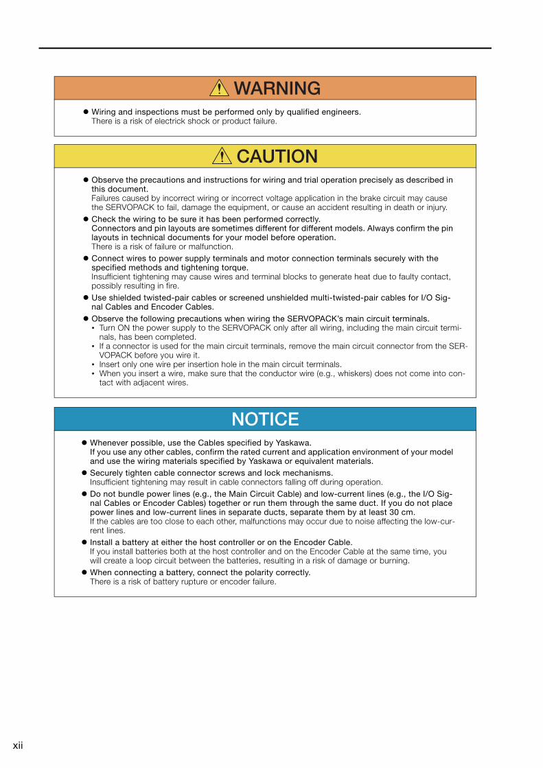
WARNINGWiring and inspections must be performed only by qualified engineers.There is a risk of electrick shock or product failure.
CAUTIONObserve the precautions and instructions for wiring and trial operation precisely as described in this document.Failures caused by incorrect wiring or incorrect voltage application in the brake circuit may cause the SERVOPACK to fail, damage the equipment, or cause an accident resulting in death or injury.Check the wiring to be sure it has been performed correctly.Connectors and pin layouts are sometimes different for different models. Always confirm the pin layouts in technical documents for your model before operation.There is a risk of failure or malfunction.Connect wires to power supply terminals and motor connection terminals securely with the specified methods and tightening torque.Insufficient tightening may cause wires and terminal blocks to generate heat due to faulty contact, possibly resulting in fire.Use shielded twisted-pair cables or screened unshielded multi-twisted-pair cables for I/O Sig-nal Cables and Encoder Cables.Observe the following precautions when wiring the SERVOPACK’s main circuit terminals.• Turn ON the power supply to the SERVOPACK only after all wiring, including the main circuit termi-
nals, has been completed.• If a connector is used for the main circuit terminals, remove the main circuit connector from the SER-
VOPACK before you wire it.• Insert only one wire per insertion hole in the main circuit terminals.• When you insert a wire, make sure that the conductor wire (e.g., whiskers) does not come into con-
tact with adjacent wires.
NOTICEWhenever possible, use the Cables specified by Yaskawa.If you use any other cables, confirm the rated current and application environment of your model and use the wiring materials specified by Yaskawa or equivalent materials.Securely tighten cable connector screws and lock mechanisms.Insufficient tightening may result in cable connectors falling off during operation.Do not bundle power lines (e.g., the Main Circuit Cable) and low-current lines (e.g., the I/O Sig-nal Cables or Encoder Cables) together or run them through the same duct. If you do not place power lines and low-current lines in separate ducts, separate them by at least 30 cm.If the cables are too close to each other, malfunctions may occur due to noise affecting the low-cur-rent lines.Install a battery at either the host controller or on the Encoder Cable.If you install batteries both at the host controller and on the Encoder Cable at the same time, you will create a loop circuit between the batteries, resulting in a risk of damage or burning.When connecting a battery, connect the polarity correctly.There is a risk of battery rupture or encoder failure.
xiii
Operation Precautions
Maintenance and Inspection Precautions
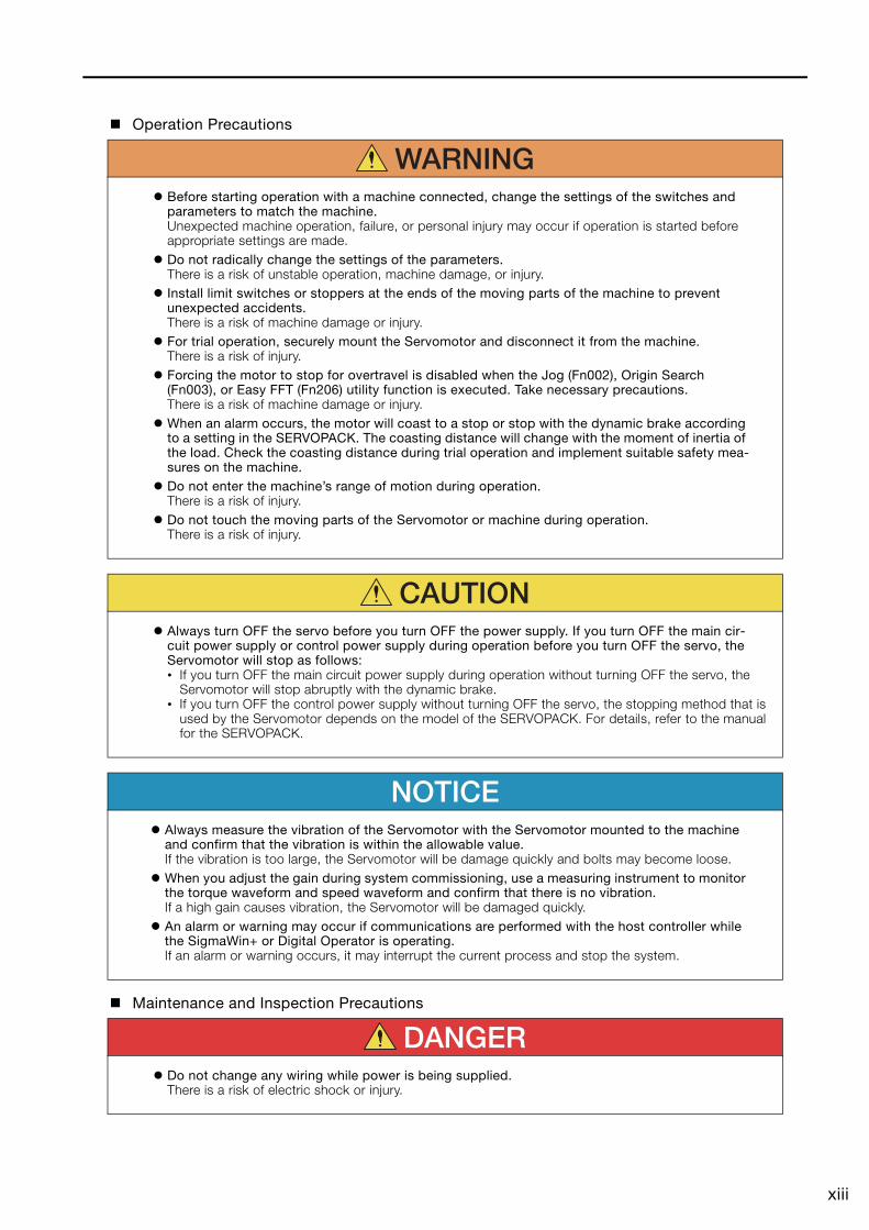
WARNINGBefore starting operation with a machine connected, change the settings of the switches and parameters to match the machine.Unexpected machine operation, failure, or personal injury may occur if operation is started before appropriate settings are made.Do not radically change the settings of the parameters.There is a risk of unstable operation, machine damage, or injury.Install limit switches or stoppers at the ends of the moving parts of the machine to prevent unexpected accidents.There is a risk of machine damage or injury.For trial operation, securely mount the Servomotor and disconnect it from the machine.There is a risk of injury.Forcing the motor to stop for overtravel is disabled when the Jog (Fn002), Origin Search (Fn003), or Easy FFT (Fn206) utility function is executed. Take necessary precautions.There is a risk of machine damage or injury.When an alarm occurs, the motor will coast to a stop or stop with the dynamic brake according to a setting in the SERVOPACK. The coasting distance will change with the moment of inertia of the load. Check the coasting distance during trial operation and implement suitable safety mea-sures on the machine.Do not enter the machine’s range of motion during operation.There is a risk of injury.Do not touch the moving parts of the Servomotor or machine during operation.There is a risk of injury.
CAUTIONAlways turn OFF the servo before you turn OFF the power supply. If you turn OFF the main cir-cuit power supply or control power supply during operation before you turn OFF the servo, the Servomotor will stop as follows:• If you turn OFF the main circuit power supply during operation without turning OFF the servo, the
Servomotor will stop abruptly with the dynamic brake.• If you turn OFF the control power supply without turning OFF the servo, the stopping method that is
used by the Servomotor depends on the model of the SERVOPACK. For details, refer to the manual for the SERVOPACK.
NOTICEAlways measure the vibration of the Servomotor with the Servomotor mounted to the machine and confirm that the vibration is within the allowable value.If the vibration is too large, the Servomotor will be damage quickly and bolts may become loose.When you adjust the gain during system commissioning, use a measuring instrument to monitor the torque waveform and speed waveform and confirm that there is no vibration.If a high gain causes vibration, the Servomotor will be damaged quickly.An alarm or warning may occur if communications are performed with the host controller while the SigmaWin+ or Digital Operator is operating.If an alarm or warning occurs, it may interrupt the current process and stop the system.
DANGERDo not change any wiring while power is being supplied.There is a risk of electric shock or injury.
xiv
Troubleshooting Precautions
Disposal Precautions
General Precautions
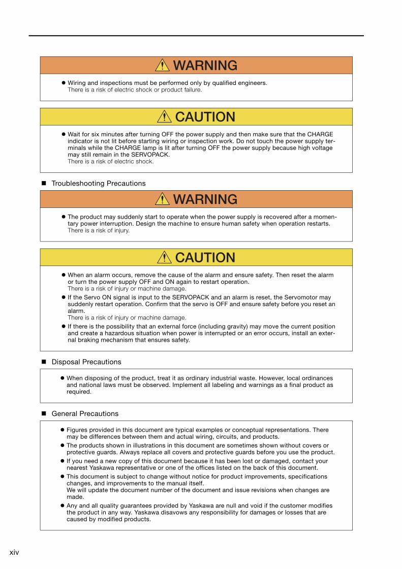
WARNINGWiring and inspections must be performed only by qualified engineers.There is a risk of electric shock or product failure.
CAUTIONWait for six minutes after turning OFF the power supply and then make sure that the CHARGE indicator is not lit before starting wiring or inspection work. Do not touch the power supply ter-minals while the CHARGE lamp is lit after turning OFF the power supply because high voltage may still remain in the SERVOPACK.There is a risk of electric shock.
WARNINGThe product may suddenly start to operate when the power supply is recovered after a momen-tary power interruption. Design the machine to ensure human safety when operation restarts.There is a risk of injury.
CAUTIONWhen an alarm occurs, remove the cause of the alarm and ensure safety. Then reset the alarm or turn the power supply OFF and ON again to restart operation.There is a risk of injury or machine damage.If the Servo ON signal is input to the SERVOPACK and an alarm is reset, the Servomotor may suddenly restart operation. Confirm that the servo is OFF and ensure safety before you reset an alarm.There is a risk of injury or machine damage.If there is the possibility that an external force (including gravity) may move the current position and create a hazardous situation when power is interrupted or an error occurs, install an exter-nal braking mechanism that ensures safety.
When disposing of the product, treat it as ordinary industrial waste. However, local ordinances and national laws must be observed. Implement all labeling and warnings as a final product as required.
Figures provided in this document are typical examples or conceptual representations. There may be differences between them and actual wiring, circuits, and products.The products shown in illustrations in this document are sometimes shown without covers or protective guards. Always replace all covers and protective guards before you use the product.If you need a new copy of this document because it has been lost or damaged, contact your nearest Yaskawa representative or one of the offices listed on the back of this document.This document is subject to change without notice for product improvements, specifications changes, and improvements to the manual itself.We will update the document number of the document and issue revisions when changes are made.Any and all quality guarantees provided by Yaskawa are null and void if the customer modifies the product in any way. Yaskawa disavows any responsibility for damages or losses that are caused by modified products.
xv
Warranty
Details of Warranty
Warranty Period
The warranty period for a product that was purchased (hereinafter called the “delivered product”) is one year from the time of delivery to the location specified by the customer or 18 months from the time of shipment from the Yaskawa factory, whichever is sooner.
Warranty Scope
Yaskawa shall replace or repair a defective product free of charge if a defect attributable to Yaskawa occurs during the above warranty period.This warranty does not cover defects caused by the delivered product reaching the end of its ser-vice life and replacement of parts that require replacement or that have a limited service life.This warranty does not cover failures that result from any of the following causes.• Improper handling, abuse, or use in unsuitable conditions or in environments not described in
product catalogs or manuals, or in any separately agreed-upon specifications • Causes not attributable to the delivered product itself • Modifications or repairs not performed by Yaskawa• Use of the delivered product in a manner in which it was not originally intended• Causes that were not foreseeable with the scientific and technological understanding at the time
of shipment from Yaskawa• Events for which Yaskawa is not responsible, such as natural or human-made disasters
Limitations of Liability• Yaskawa shall in no event be responsible for any damage or loss of opportunity to the customer
that arises due to failure of the delivered product.• Yaskawa shall not be responsible for any programs (including parameter settings) or the results of
program execution of the programs provided by the user or by a third party for use with program-mable Yaskawa products.
• The information described in product catalogs or manuals is provided for the purpose of the cus-tomer purchasing the appropriate product for the intended application. The use thereof does not guarantee that there are no infringements of intellectual property rights or other proprietary rights of Yaskawa or third parties, nor does it construe a license.
• Yaskawa shall not be responsible for any damage arising from infringements of intellectual prop-erty rights or other proprietary rights of third parties as a result of using the information described in catalogs or manuals.
xvi
Suitability for Use• It is the customer’s responsibility to confirm conformity with any standards, codes, or regulations
that apply if the Yaskawa product is used in combination with any other products.• The customer must confirm that the Yaskawa product is suitable for the systems, machines, and
equipment used by the customer.• Consult with Yaskawa to determine whether use in the following applications is acceptable. If use
in the application is acceptable, use the product with extra allowance in ratings and specifica-tions, and provide safety measures to minimize hazards in the event of failure.
• Outdoor use, use involving potential chemical contamination or electrical interference, or use in conditions or environments not described in product catalogs or manuals
• Nuclear energy control systems, combustion systems, railroad systems, aviation systems, vehicle systems, medical equipment, amusement machines, and installations subject to sep-arate industry or government regulations
• Systems, machines, and equipment that may present a risk to life or property• Systems that require a high degree of reliability, such as systems that supply gas, water, or
electricity, or systems that operate continuously 24 hours a day• Other systems that require a similar high degree of safety
• Never use the product for an application involving serious risk to life or property without first ensuring that the system is designed to secure the required level of safety with risk warnings and redundancy, and that the Yaskawa product is properly rated and installed.
• The circuit examples and other application examples described in product catalogs and manuals are for reference. Check the functionality and safety of the actual devices and equipment to be used before using the product.
• Read and understand all use prohibitions and precautions, and operate the Yaskawa product correctly to prevent accidental harm to third parties.
Specifications ChangeThe names, specifications, appearance, and accessories of products in product catalogs and manuals may be changed at any time based on improvements and other reasons. The next edi-tions of the revised catalogs or manuals will be published with updated code numbers. Consult with your Yaskawa representative to confirm the actual specifications before purchasing a product.
xvii
Compliance with UL Standards, EU Directives, and Other Safety Standards
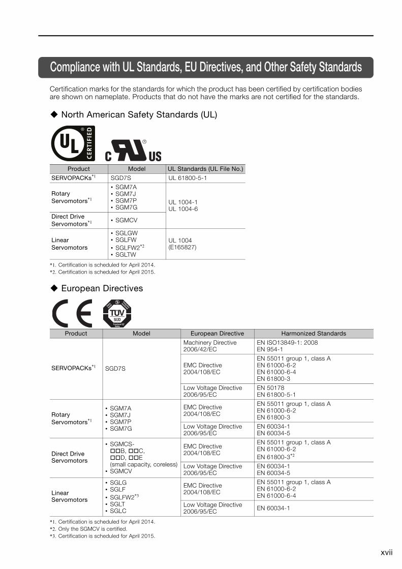
Certification marks for the standards for which the product has been certified by certification bodies are shown on nameplate. Products that do not have the marks are not certified for the standards.
North American Safety Standards (UL)
*1. Certification is scheduled for April 2014.*2. Certification is scheduled for April 2015.
European Directives
*1. Certification is scheduled for April 2014.*2. Only the SGMCV is certified.*3. Certification is scheduled for April 2015.
Product Model UL Standards (UL File No.)
SERVOPACKs*1 SGD7S UL 61800-5-1
Rotary Servomotors*1
• SGM7A• SGM7J• SGM7P• SGM7G
UL 1004-1UL 1004-6
Direct Drive Servomotors*1 • SGMCV
Linear Servomotors
• SGLGW• SGLFW• SGLFW2*2
• SGLTW
UL 1004(E165827)
Product Model European Directive Harmonized Standards
SERVOPACKs*1 SGD7S
Machinery Directive2006/42/EC
EN ISO13849-1: 2008EN 954-1
EMC Directive2004/108/EC
EN 55011 group 1, class AEN 61000-6-2EN 61000-6-4EN 61800-3
Low Voltage Directive2006/95/EC
EN 50178EN 61800-5-1
Rotary Servomotors*1
• SGM7A• SGM7J• SGM7P• SGM7G
EMC Directive2004/108/EC
EN 55011 group 1, class AEN 61000-6-2EN 61800-3
Low Voltage Directive2006/95/EC
EN 60034-1EN 60034-5
Direct Drive Servomotors
• SGMCS-B, C, D, E
(small capacity, coreless)• SGMCV
EMC Directive2004/108/EC
EN 55011 group 1, class AEN 61000-6-2EN 61800-3*2
Low Voltage Directive2006/95/EC
EN 60034-1EN 60034-5
Linear Servomotors
• SGLG• SGLF• SGLFW2*3
• SGLT• SGLC
EMC Directive2004/108/EC
EN 55011 group 1, class AEN 61000-6-2EN 61000-6-4
Low Voltage Directive2006/95/EC EN 60034-1
xviii
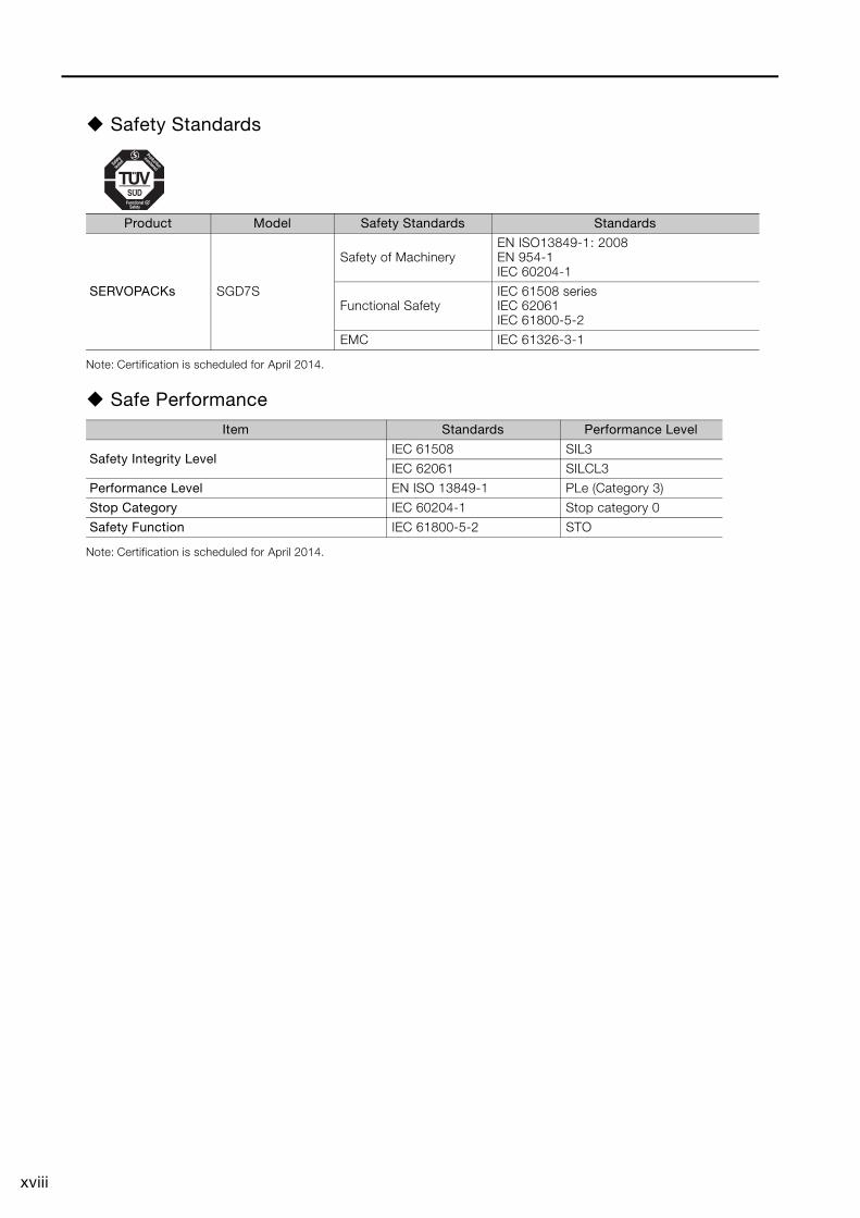
Safety Standards
Note: Certification is scheduled for April 2014.
Safe Performance
Note: Certification is scheduled for April 2014.
Product Model Safety Standards Standards
SERVOPACKs SGD7S
Safety of MachineryEN ISO13849-1: 2008EN 954-1 IEC 60204-1
Functional SafetyIEC 61508 seriesIEC 62061IEC 61800-5-2
EMC IEC 61326-3-1
Item Standards Performance Level
Safety Integrity LevelIEC 61508 SIL3
IEC 62061 SILCL3
Performance Level EN ISO 13849-1 PLe (Category 3)
Stop Category IEC 60204-1 Stop category 0
Safety Function IEC 61800-5-2 STO
xix
ContentsAbout this Manual. . . . . . . . . . . . . . . . . . . . . . . . . . . . . . . . . . . . . . . . . . . . . . . . . iiiOutline of Manual . . . . . . . . . . . . . . . . . . . . . . . . . . . . . . . . . . . . . . . . . . . . . . . . . iiiRelated Documents . . . . . . . . . . . . . . . . . . . . . . . . . . . . . . . . . . . . . . . . . . . . . . . ivUsing This Manual . . . . . . . . . . . . . . . . . . . . . . . . . . . . . . . . . . . . . . . . . . . . . . . viiSafety Precautions . . . . . . . . . . . . . . . . . . . . . . . . . . . . . . . . . . . . . . . . . . . . . . . viiiWarranty . . . . . . . . . . . . . . . . . . . . . . . . . . . . . . . . . . . . . . . . . . . . . . . . . . . . . . . xvCompliance with UL Standards, EU Directives, and Other Safety Standards . . xvii
Basic Information on Servomotors1
1.1 Servomotor Part Names . . . . . . . . . . . . . . . . . . . . . . . . . . . . . . . 1-21.1.1 SGMCS . . . . . . . . . . . . . . . . . . . . . . . . . . . . . . . . . . . . . . . . . . . . . . . . . . . . 1-21.1.2 SGMCV . . . . . . . . . . . . . . . . . . . . . . . . . . . . . . . . . . . . . . . . . . . . . . . . . . . . 1-2
1.2 Nameplate . . . . . . . . . . . . . . . . . . . . . . . . . . . . . . . . . . . . . . . . . 1-31.2.1 SGMCS . . . . . . . . . . . . . . . . . . . . . . . . . . . . . . . . . . . . . . . . . . . . . . . . . . . . 1-31.2.2 SGMCV . . . . . . . . . . . . . . . . . . . . . . . . . . . . . . . . . . . . . . . . . . . . . . . . . . . . 1-3
1.3 Outline of Model Designations . . . . . . . . . . . . . . . . . . . . . . . . . . 1-41.3.1 Servomotors . . . . . . . . . . . . . . . . . . . . . . . . . . . . . . . . . . . . . . . . . . . . . . . . 1-41.3.2 SERVOPACKs . . . . . . . . . . . . . . . . . . . . . . . . . . . . . . . . . . . . . . . . . . . . . . . 1-4
1.4 Combinations of Servomotors and SERVOPACKs . . . . . . . . . . . 1-5
Capacity Selection2
2.1 Selecting the Servomotor Capacity . . . . . . . . . . . . . . . . . . . . . . 2-2
Specifications, Ratings, and External Dimensions of SGMCS Servomotors3
3.1 Model Designations . . . . . . . . . . . . . . . . . . . . . . . . . . . . . . . . . . 3-2
3.2 Specifications and Ratings . . . . . . . . . . . . . . . . . . . . . . . . . . . . 3-33.2.1 Small-Capacity, Coreless Servomotors: Specifications . . . . . . . . . . . . . . . . 3-33.2.2 Small-Capacity, Coreless Servomotors: Ratings . . . . . . . . . . . . . . . . . . . . . 3-53.2.3 Small-Capacity, Coreless Servomotors:
Torque-Motor Speed Characteristics . . . . . . . . . . . . . . . . . . . . . . . . . . . . . . 3-63.2.4 Small-Capacity, Coreless Servomotors:
Servomotor Overload Protection Characteristics . . . . . . . . . . . . . . . . . . . . . 3-73.2.5 Medium-Capacity Servomotors with Cores: Specifications . . . . . . . . . . . . . 3-83.2.6 Medium-Capacity Servomotors with Cores: Ratings . . . . . . . . . . . . . . . . . 3-103.2.7 Medium-Capacity Servomotors with Cores:
Torque-Motor Speed Characteristics . . . . . . . . . . . . . . . . . . . . . . . . . . . . . 3-113.2.8 Medium-Capacity Servomotors with Cores:
Servomotor Overload Protection Characteristics . . . . . . . . . . . . . . . . . . . . 3-123.2.9 Load Moment of Inertia . . . . . . . . . . . . . . . . . . . . . . . . . . . . . . . . . . . . . . . 3-133.2.10 Allowable Load Moment of Inertia Scaling Factor for
SERVOPACKs without Built-in Regenerative Resistors . . . . . . . . . . . . . . . 3-14
xx
3.3 External Dimensions . . . . . . . . . . . . . . . . . . . . . . . . . . . . . . . . 3-153.3.1 Small-Capacity, Coreless Servomotors. . . . . . . . . . . . . . . . . . . . . . . . . . . .3-153.3.2 Medium-Capacity Servomotors with Cores . . . . . . . . . . . . . . . . . . . . . . . .3-193.3.3 Connector Specifications . . . . . . . . . . . . . . . . . . . . . . . . . . . . . . . . . . . . . .3-21
Specifications, Ratings, and External Dimensions of SGMCV Servomotors4
4.1 Model Designations . . . . . . . . . . . . . . . . . . . . . . . . . . . . . . . . . . 4-2
4.2 Specifications and Ratings . . . . . . . . . . . . . . . . . . . . . . . . . . . . 4-34.2.1 Specifications. . . . . . . . . . . . . . . . . . . . . . . . . . . . . . . . . . . . . . . . . . . . . . . .4-34.2.2 Ratings . . . . . . . . . . . . . . . . . . . . . . . . . . . . . . . . . . . . . . . . . . . . . . . . . . . . .4-54.2.3 Torque-Motor Speed Characteristics . . . . . . . . . . . . . . . . . . . . . . . . . . . . . .4-64.2.4 Servomotor Overload Protection Characteristics . . . . . . . . . . . . . . . . . . . . .4-64.2.5 Load Moment of Inertia . . . . . . . . . . . . . . . . . . . . . . . . . . . . . . . . . . . . . . . .4-74.2.6 Allowable Load Moment of Inertia Scaling Factor for
SERVOPACKs without Built-in Regenerative Resistors . . . . . . . . . . . . . . . . .4-8
4.3 External Dimensions . . . . . . . . . . . . . . . . . . . . . . . . . . . . . . . . . 4-94.3.1 Connector Specifications . . . . . . . . . . . . . . . . . . . . . . . . . . . . . . . . . . . . . .4-11
Servomotor Installation5
5.1 Installation Conditions . . . . . . . . . . . . . . . . . . . . . . . . . . . . . . . . 5-25.1.1 Installation Precautions . . . . . . . . . . . . . . . . . . . . . . . . . . . . . . . . . . . . . . . .5-25.1.2 Installation Environment . . . . . . . . . . . . . . . . . . . . . . . . . . . . . . . . . . . . . . . .5-35.1.3 Installation Orientation . . . . . . . . . . . . . . . . . . . . . . . . . . . . . . . . . . . . . . . . .5-3
5.2 Mounting to the Machine . . . . . . . . . . . . . . . . . . . . . . . . . . . . . . 5-4
5.3 Oil and Water Countermeasures . . . . . . . . . . . . . . . . . . . . . . . . 5-5
5.4 Equipment Structure . . . . . . . . . . . . . . . . . . . . . . . . . . . . . . . . . 5-65.4.1 Minimum Angle of Oscillation . . . . . . . . . . . . . . . . . . . . . . . . . . . . . . . . . . . .5-65.4.2 Precautions on Passing the Origin . . . . . . . . . . . . . . . . . . . . . . . . . . . . . . . .5-6
5.5 Servomotor Temperature Increase . . . . . . . . . . . . . . . . . . . . . . . 5-7
Connections between Servomotors and SERVOPACKs6
6.1 Selecting Cables . . . . . . . . . . . . . . . . . . . . . . . . . . . . . . . . . . . . 6-26.1.1 System Configurations . . . . . . . . . . . . . . . . . . . . . . . . . . . . . . . . . . . . . . . . .6-26.1.2 Servomotor Main Circuit Cables . . . . . . . . . . . . . . . . . . . . . . . . . . . . . . . . . .6-26.1.3 Encoder Cables of 20 m or Less. . . . . . . . . . . . . . . . . . . . . . . . . . . . . . . . . .6-46.1.4 Relay Encoder Cables of 30 m to 50 m. . . . . . . . . . . . . . . . . . . . . . . . . . . . .6-6
6.2 Wiring Servomotors and SERVOPACKs . . . . . . . . . . . . . . . . . . . 6-86.2.1 Wiring Precautions . . . . . . . . . . . . . . . . . . . . . . . . . . . . . . . . . . . . . . . . . . . .6-86.2.2 Wiring Procedure . . . . . . . . . . . . . . . . . . . . . . . . . . . . . . . . . . . . . . . . . . . .6-10
xxi
Maintenance and Inspection7
7.1 Periodic Inspections. . . . . . . . . . . . . . . . . . . . . . . . . . . . . . . . . . 7-2
7.2 Service Lives of Parts. . . . . . . . . . . . . . . . . . . . . . . . . . . . . . . . . 7-3
7.3 Disposing of Servomotors . . . . . . . . . . . . . . . . . . . . . . . . . . . . . 7-4
Appendix8
8.1 Reference Information for Servomotor Capacity Selection . . . . 8-28.1.1 GD2 for Simple Diagrams . . . . . . . . . . . . . . . . . . . . . . . . . . . . . . . . . . . . . . 8-28.1.2 Conversions between Traditional Units and SI Units . . . . . . . . . . . . . . . . . . 8-3
Revision History
This chapter provides basic information on Direct Drive Servomotors, including Servomotor part names and com-binations with SERVOPACKs.
1.1 Servomotor Part Names . . . . . . . . . . . . . . . 1-21.1.1 SGMCS . . . . . . . . . . . . . . . . . . . . . . . . . . . . . . . . 1-21.1.2 SGMCV . . . . . . . . . . . . . . . . . . . . . . . . . . . . . . . . 1-2
1.2 Nameplate . . . . . . . . . . . . . . . . . . . . . . . . . . 1-31.2.1 SGMCS . . . . . . . . . . . . . . . . . . . . . . . . . . . . . . . . 1-31.2.2 SGMCV . . . . . . . . . . . . . . . . . . . . . . . . . . . . . . . . 1-3
1.3 Outline of Model Designations . . . . . . . . . . 1-41.3.1 Servomotors . . . . . . . . . . . . . . . . . . . . . . . . . . . . 1-41.3.2 SERVOPACKs . . . . . . . . . . . . . . . . . . . . . . . . . . . 1-4
1.4 Combinations of Servomotors and SERVOPACKs . .1-5
Basic Information on Servomotors 1
1.1 Servomotor Part Names
1.1.1 SGMCS
1-2
1.1 Servomotor Part Names
1.1.1 SGMCS
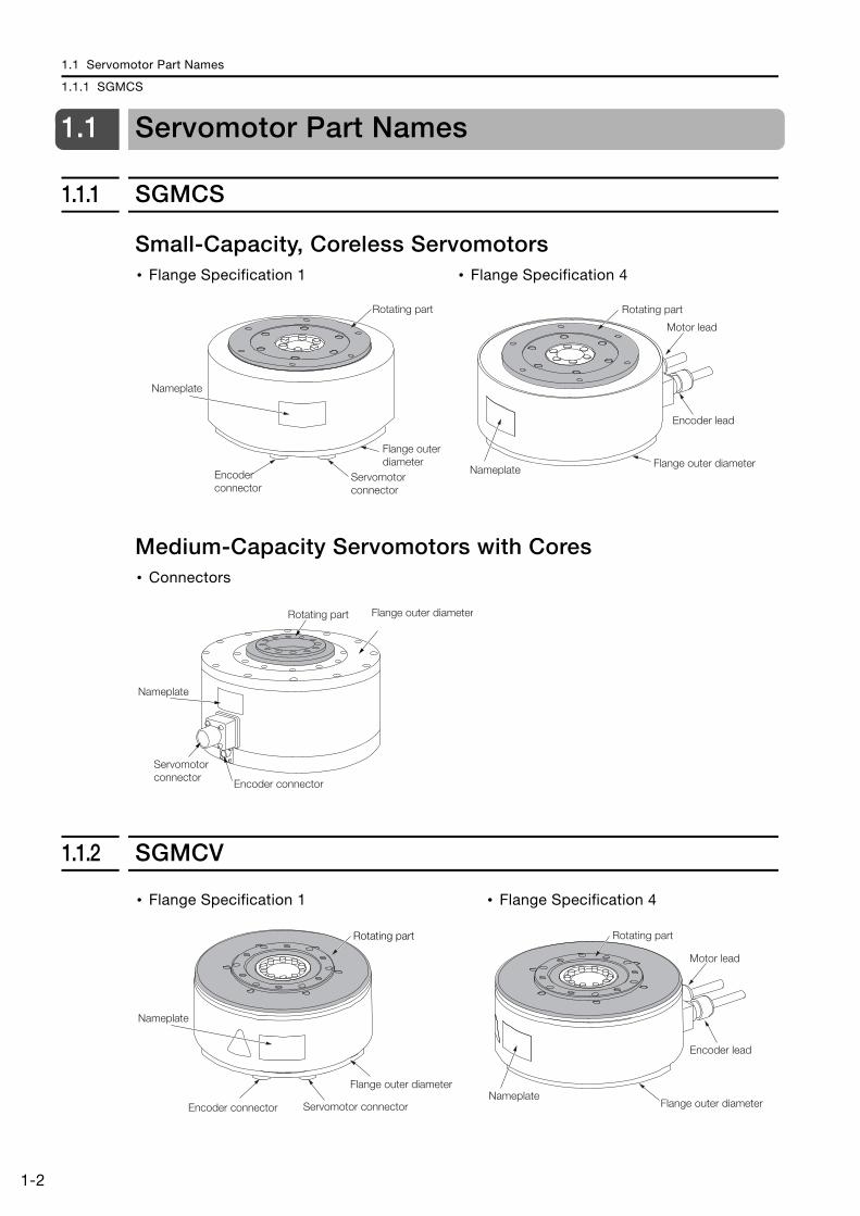
Small-Capacity, Coreless Servomotors
Medium-Capacity Servomotors with Cores
1.1.2 SGMCV
• Flange Specification 1 • Flange Specification 4
• Connectors
Nameplate
Servomotor connector
Rotating part
Flange outer diameter
Encoder connector
Nameplate
Rotating part
Motor lead
Encoder lead
Flange outer diameter
Servomotor connector
Encoder connector
Nameplate
Rotating part Flange outer diameter
• Flange Specification 1 • Flange Specification 4
Rotating part
Servomotor connector
Flange outer diameter
Encoder connector
Nameplate
Nameplate
Rotating part
Motor lead
Encoder lead
Flange outer diameter
1.2 Nameplate
1.2.1 SGMCS
1B
asic
Info
rmat
ion
on S
ervo
mot
ors
1-3
1.2 Nameplate
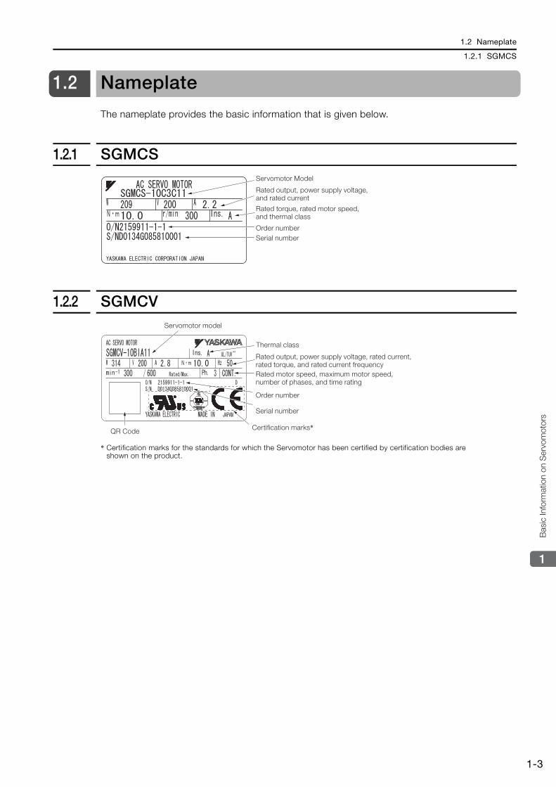
The nameplate provides the basic information that is given below.
1.2.1 SGMCS
1.2.2 SGMCV
* Certification marks for the standards for which the Servomotor has been certified by certification bodies are shown on the product.
Rated output, power supply voltage, and rated current
Rated torque, rated motor speed, and thermal class
Order numberSerial number
Servomotor Model
QR Code
Thermal class
Rated output, power supply voltage, rated current, rated torque, and rated current frequencyRated motor speed, maximum motor speed, number of phases, and time rating
Order number
Serial number
Certification marks*
Servomotor model
1.3 Outline of Model Designations
1.3.1 Servomotors
1-4
1.3 Outline of Model Designations
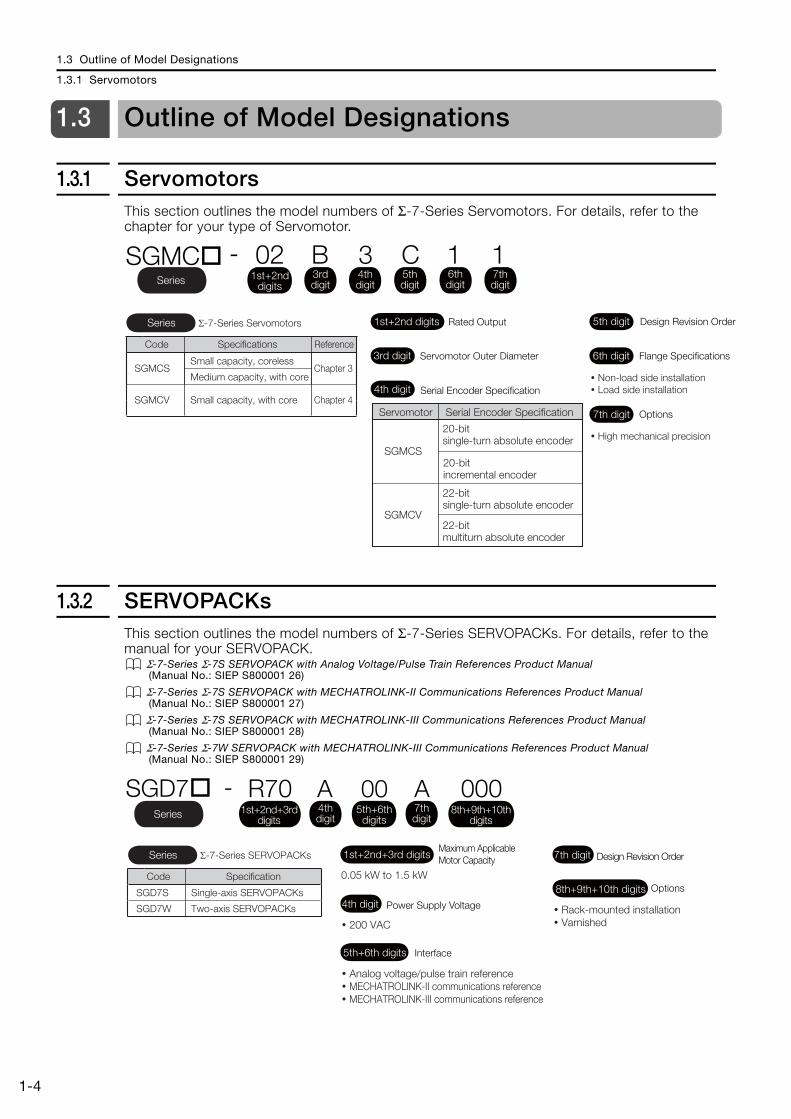
1.3.1 ServomotorsThis section outlines the model numbers of Σ-7-Series Servomotors. For details, refer to the chapter for your type of Servomotor.
1.3.2 SERVOPACKsThis section outlines the model numbers of Σ-7-Series SERVOPACKs. For details, refer to the manual for your SERVOPACK.
Σ-7-Series Σ-7S SERVOPACK with Analog Voltage/Pulse Train References Product Manual (Manual No.: SIEP S800001 26)
Σ-7-Series Σ-7S SERVOPACK with MECHATROLINK-II Communications References Product Manual (Manual No.: SIEP S800001 27)
Σ-7-Series Σ-7S SERVOPACK with MECHATROLINK-III Communications References Product Manual (Manual No.: SIEP S800001 28)
Σ-7-Series Σ-7W SERVOPACK with MECHATROLINK-III Communications References Product Manual (Manual No.: SIEP S800001 29)
Code Specifications Reference
SGMCS Chapter 3
SGMCV Chapter 4
� Non-load side installation� Load side installation
� High mechanical precision
Small capacity, coreless
Medium capacity, with core
Small capacity, with core
Σ-7-Series ServomotorsSeries 1st+2nd digits Rated Output
3rd digit Servomotor Outer Diameter
4th digit Serial Encoder Specification
5th digit Design Revision Order
7th digit Options
6th digit Flange Specifications
Series
SGMC - 02 B 3 C 1 11st+2nd
digits3rd digit
4th digit
5th digit
6th digit
7th digit
Servomotor Serial Encoder Specification
SGMCS
SGMCV22-bit multiturn absolute encoder
20-bit single-turn absolute encoder
20-bit incremental encoder
22-bit single-turn absolute encoder
Code Specification
SGD7S
SGD7W
Single-axis SERVOPACKs
Two-axis SERVOPACKs
0.05 kW to 1.5 kW
� 200 VAC
� Analog voltage/pulse train reference� MECHATROLINK-II communications reference� MECHATROLINK-III communications reference
� Rack-mounted installation� Varnished
Σ-7-Series SERVOPACKsSeriesMaximum Applicable Motor Capacity1st+2nd+3rd digits
Power Supply Voltage4th digit
Options8th+9th+10th digits
Interface5th+6th digits
Design Revision Order7th digit
SGD7 - R70 000 A A004th digit
1st+2nd+3rd digits
5th+6th digits
8th+9th+10th digits
7th digitSeries
1.4 Combinations of Servomotors and SERVOPACKs
1B
asic
Info
rmat
ion
on S
ervo
mot
ors
1-5
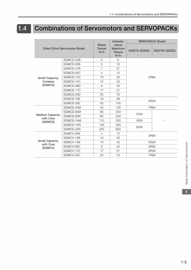
1.4 Combinations of Servomotors and SERVOPACKs
Direct Drive Servomotor ModelRated Torque
N m
Instanta-neous
Maximum Torque
N m
SERVOPACK Model
SGD7S- SGD7W-
Small Capacity, Coreless (SGMCS)
SGMCS-02B 2 6
2R8A
SGMCS-05B 5 15
SGMCS-07B 7 21
SGMCS-04C 4 12
SGMCS-10C 10 30
SGMCS-14C 14 42
SGMCS-08D 8 24
SGMCS-17D 17 51
SGMCS-25D 25 75
SGMCS-16E 16 485R5A
SGMCS-35E 35 105
Medium Capacity, with Core (SGMCS)
SGMCS-45M 45 135 7R6A
SGMCS-80M 80 240120A
−SGMCS-80N 80 240
SGMCS-1AM 110 330 180A
SGMCS-1EN 150 450200A
SGMCS-2ZN 200 600
Small Capacity, with Core(SGMCV)
SGMCV-04B 4 122R8A
SGMCV-10B 10 30
SGMCV-14B 14 42 5R5A
SGMCV-08C 8 24 2R8A
SGMCV-17C 17 51 5R5A
SGMCV-25C 25 75 7R6A
This chapter describes calculation methods to use when selecting Servomotor capacities.
2.1 Selecting the Servomotor Capacity . . . . . . 2-2
Capacity Selection 2
2.1 Selecting the Servomotor Capacity
2-2
2.1 Selecting the Servomotor Capacity
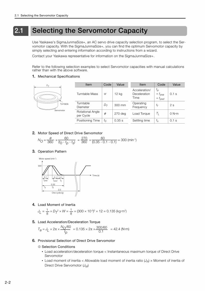
Use Yaskawa's SigmaJunmaSize+, an AC servo drive capacity selection program, to select the Ser-vomotor capacity. With the SigmaJunmaSize+, you can find the optimum Servomotor capacity by simply selecting and entering information according to instructions from a wizard.
Contact your Yaskawa representative for information on the SigmaJunmaSize+.
Refer to the following selection examples to select Servomotor capacities with manual calculations rather than with the above software.
1. Mechanical Specifications
2. Motor Speed of Direct Drive Servomotor
3. Operation Pattern
4. Load Moment of Inertia
5. Load Acceleration/Deceleration Torque
6. Provisional Selection of Direct Drive Servomotor
Selection Conditions• Load acceleration/deceleration torque < Instantaneous maximum torque of Direct Drive
Servomotor• Load moment of inertia < Allowable load moment of inertia ratio (JR) × Moment of inertia of
Direct Drive Servomotor (JM)
Turntable
Servomotor
DTItem Code Value Item Code Value
Turntable Mass W 12 kgAcceleration/Deceleration Time
tp= tpsa= tpsd
0.1 s
Turntable Diameter
DT 300 mmOperating Frequency
tf 2 s
Rotational Angle per Cycle
θ 270 deg Load Torque TL 0 N m
Positioning Time t0 0.35 s Settling time ts 0.1 s
NO = × = × = 300 (min-1) 360 (t0 - tp - ts)θ
360 (0.35 - 0.1 - 0.1)270 6060
300
0.1 0.1 0.1ts
2.0
0.35
Motor speed (min-1)
Time (s)
One cycle (tf)
t0ts
tpsdtpsa
81
81JL = × DT
2 × W = × (300 × 10-3)2 × 12 = 0.135 (kg�m2)
Ta = JL × 2π × = 0.135 × 2π × = 42.4 (N�m) NO/60
tp300/60
0.1
2.1 Selecting the Servomotor Capacity
2-3
2
Cap
acity
Sel
ectio
n
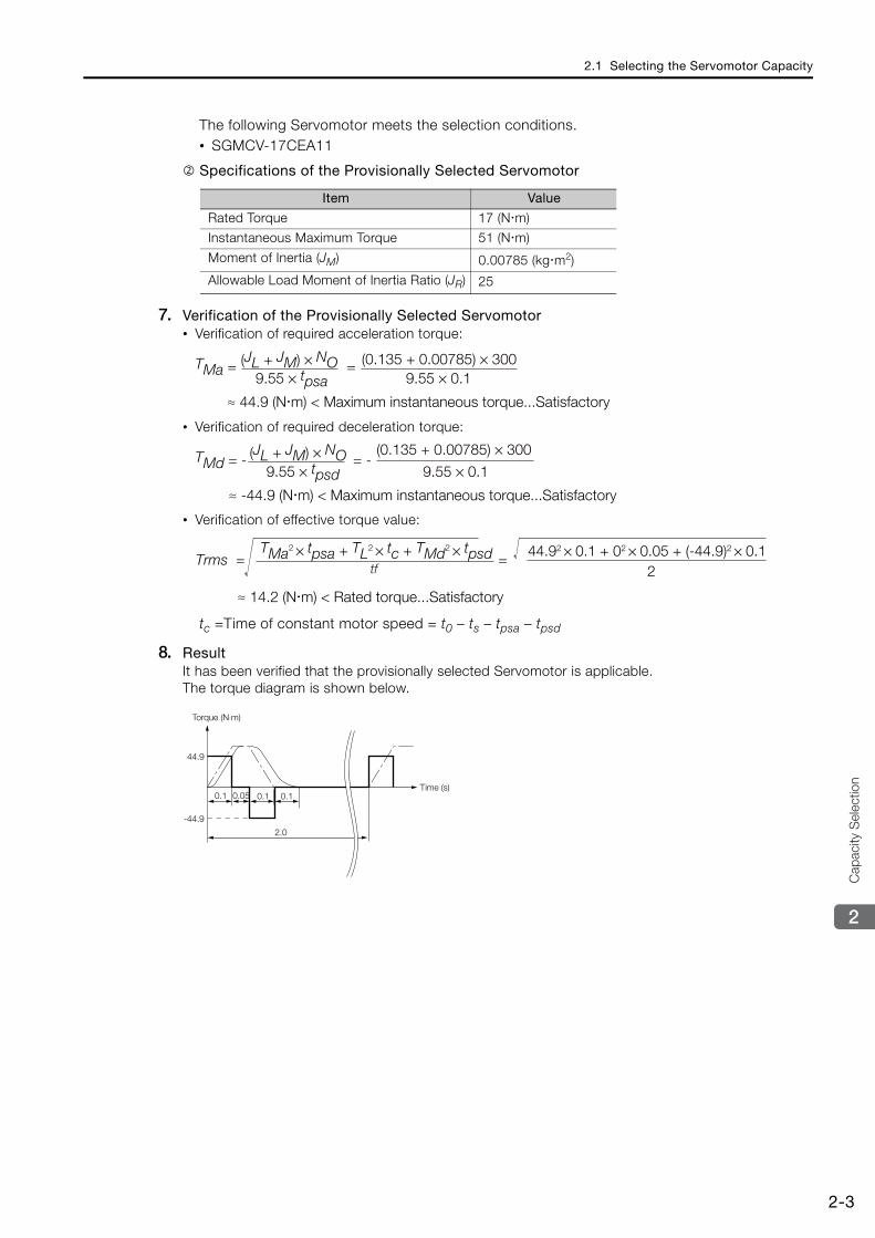
The following Servomotor meets the selection conditions.• SGMCV-17CEA11
Specifications of the Provisionally Selected Servomotor
7. Verification of the Provisionally Selected Servomotor• Verification of required acceleration torque:
• Verification of required deceleration torque:
• Verification of effective torque value:
tc =Time of constant motor speed = t0 – ts – tpsa – tpsd
8. Result It has been verified that the provisionally selected Servomotor is applicable.The torque diagram is shown below.
Item Value
Rated Torque 17 (N m)
Instantaneous Maximum Torque 51 (N m)
Moment of Inertia (JM) 0.00785 (kg m2)
Allowable Load Moment of Inertia Ratio (JR) 25
TMa = =
≈ 44.9 (N m) < Maximum instantaneous torque...Satisfactory
(JL + JM) × NO9.55 × tpsa
(0.135 + 0.00785) × 3009.55 × 0.1
TMd = - = -
≈ -44.9 (N m) < Maximum instantaneous torque...Satisfactory
(JL + JM) × NO9.55 × tpsd
(0.135 + 0.00785) × 300
9.55 × 0.1
Trms = =TMa2 × tpsa + TL2 × tc + TMd2 × tpsd
244.92 × 0.1 + 02 × 0.05 + (-44.9)2 × 0.1
≈ 14.2 (N m) < Rated torque...Satisfactory
tf
Torque (N⋅m)
Time (s)
-44.9
0.05
44.9
0.1 0.1 0.1
2.0
This chapter describes how to interpret the model numbers of SGMCS Servomotors and gives their specifications, rat-ings, and external dimensions.
3.1 Model Designations . . . . . . . . . . . . . . . . . . 3-2
3.2 Specifications and Ratings . . . . . . . . . . . . . 3-33.2.1 Small-Capacity, Coreless Servomotors:
Specifications . . . . . . . . . . . . . . . . . . . . . . . . . . . 3-33.2.2 Small-Capacity, Coreless Servomotors: Ratings . 3-53.2.3 Small-Capacity, Coreless Servomotors:
Torque-Motor Speed Characteristics . . . . . . . . . 3-63.2.4 Small-Capacity, Coreless Servomotors:
Servomotor Overload Protection Characteristics 3-73.2.5 Medium-Capacity Servomotors with Cores:
Specifications . . . . . . . . . . . . . . . . . . . . . . . . . . . 3-83.2.6 Medium-Capacity Servomotors with Cores:
Ratings . . . . . . . . . . . . . . . . . . . . . . . . . . . . . . . 3-103.2.7 Medium-Capacity Servomotors with Cores:
Torque-Motor Speed Characteristics . . . . . . . . 3-113.2.8 Medium-Capacity Servomotors with Cores:
Servomotor Overload Protection Characteristics 3-123.2.9 Load Moment of Inertia . . . . . . . . . . . . . . . . . . . 3-133.2.10 Allowable Load Moment of Inertia Scaling
Factor for SERVOPACKs without Built-in Regenerative Resistors . . . . . . . . . . . . . . . . . . . 3-14
3.3 External Dimensions . . . . . . . . . . . . . . . . . 3-153.3.1 Small-Capacity, Coreless Servomotors . . . . . . . 3-153.3.2 Medium-Capacity Servomotors with Cores . . . . 3-193.3.3 Connector Specifications . . . . . . . . . . . . . . . . . 3-21
Specifications, Ratings, and External Dimensions of SGMCS Servomotors 3
3.1 Model Designations
3-2
3.1 Model Designations
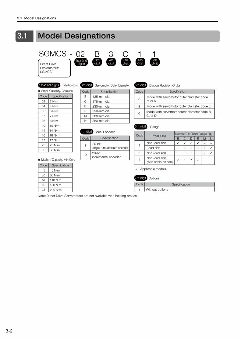
Note: Direct Drive Servomotors are not available with holding brakes.
A
B
C
B
C
D
E
M
N
3
D
B
−−
C
−−
D
−−
E
−−
M−
−
N−
−
1
3
4
1
02 2 N m
04 4 N m
05 5 N m
07 7 N m
08 8 N m
10 10 N m
14 14 N m
16 16 N m
17 17 N m
25 25 N m
35 35 N m
45 45 N m
80 80 N m
1A 110 N m
1E 150 N m
2Z 200 N m
3rd digit 5th digit
6th digit
7th digit
Small-Capacity, Coreless
Medium-Capacity, with Core
Model with servomotor outer diameter code M or N
Model with servomotor outer diameter code E
Model with servomotor outer diameter code B, C, or D
135-mm dia.
Specification
175-mm dia.
230-mm dia.290-mm dia.
280-mm dia.360-mm dia.
Servomotor Outer Diameter
4th digit Serial Encoder
Specification
20-bit single-turn absolute encoder
20-bit incremental encoder
Design Revision Order
Flange
Mounting
Non-load side
Load side
Non-load side
Non-load side (with cable on side)
: Applicable models.
Options
Without options
Servomotor Outer Diameter Code (3rd Digit)
SGMCS - 02 B 3 C 1 11st+2nd
digits
1st+2nd digits Rated Output
Specification
Code Specification
3rd digit
4th digit
5th digit
6th digit
7th digitDirect Drive
Servomotors: SGMCS
Code
Code Specification
SpecificationCode
Code
Code
Code
3.2 Specifications and Ratings
3.2.1 Small-Capacity, Coreless Servomotors: Specifications
3-3
3
Spe
cific
atio
ns, R
atin
gs, a
nd E
xter
nal D
imen
sion
s of
SG
MCS
Ser
vom
otors
3.2 Specifications and Ratings
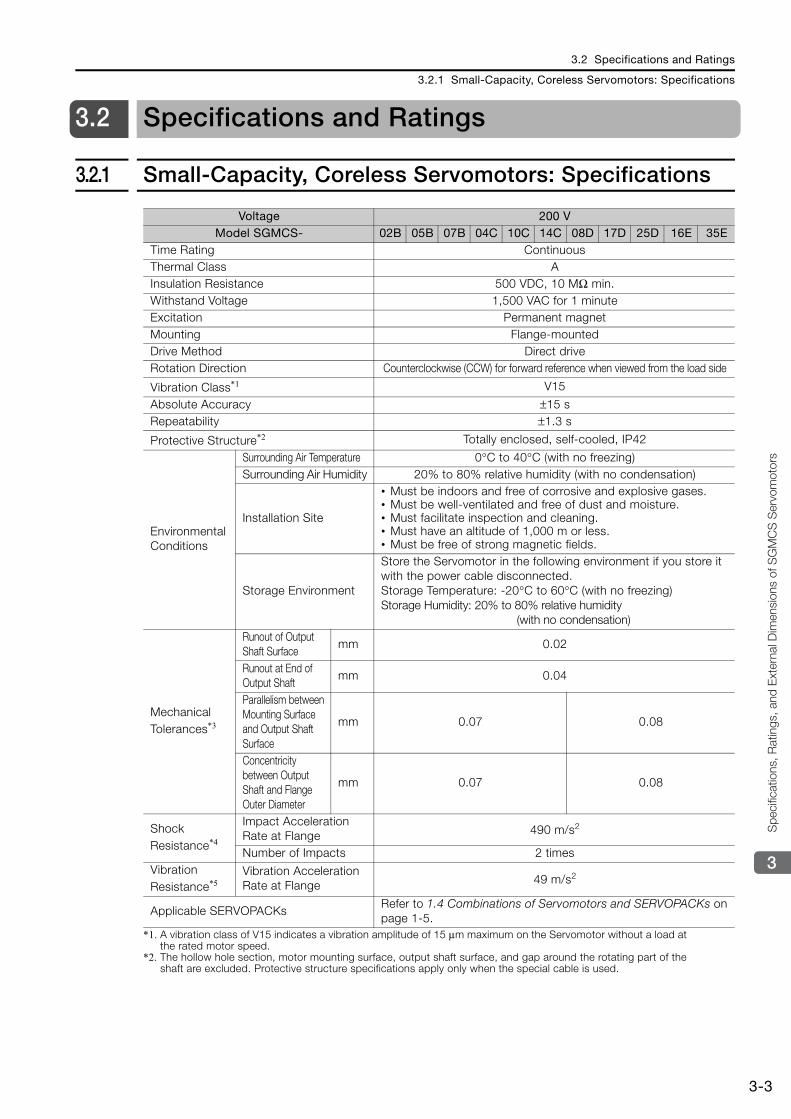
3.2.1 Small-Capacity, Coreless Servomotors: Specifications
*1. A vibration class of V15 indicates a vibration amplitude of 15 μm maximum on the Servomotor without a load at the rated motor speed.
*2. The hollow hole section, motor mounting surface, output shaft surface, and gap around the rotating part of the shaft are excluded. Protective structure specifications apply only when the special cable is used.
Voltage 200 VModel SGMCS- 02B 05B 07B 04C 10C 14C 08D 17D 25D 16E 35E
Time Rating Continuous Thermal Class AInsulation Resistance 500 VDC, 10 MΩ min. Withstand Voltage 1,500 VAC for 1 minute Excitation Permanent magnet Mounting Flange-mounted Drive Method Direct drive Rotation Direction Counterclockwise (CCW) for forward reference when viewed from the load side
Vibration Class*1 V15
Absolute Accuracy ±15 s Repeatability ±1.3 s
Protective Structure*2 Totally enclosed, self-cooled, IP42
Environmental Conditions
Surrounding Air Temperature 0°C to 40°C (with no freezing) Surrounding Air Humidity 20% to 80% relative humidity (with no condensation)
Installation Site
• Must be indoors and free of corrosive and explosive gases. • Must be well-ventilated and free of dust and moisture. • Must facilitate inspection and cleaning. • Must have an altitude of 1,000 m or less.• Must be free of strong magnetic fields.
Storage Environment
Store the Servomotor in the following environment if you store it with the power cable disconnected.Storage Temperature: -20°C to 60°C (with no freezing) Storage Humidity: 20% to 80% relative humidity
(with no condensation)
Mechanical Tolerances*3
Runout of Output Shaft Surface
mm 0.02
Runout at End of Output Shaft
mm 0.04
Parallelism between Mounting Surface and Output Shaft Surface
mm 0.07 0.08
Concentricity between Output Shaft and Flange Outer Diameter
mm 0.07 0.08
Shock Resistance*4
Impact Acceleration Rate at Flange 490 m/s2
Number of Impacts 2 times Vibration Resistance*5
Vibration Acceleration Rate at Flange 49 m/s2
Applicable SERVOPACKs Refer to 1.4 Combinations of Servomotors and SERVOPACKs on page 1-5.
3.2 Specifications and Ratings
3.2.1 Small-Capacity, Coreless Servomotors: Specifications
3-4
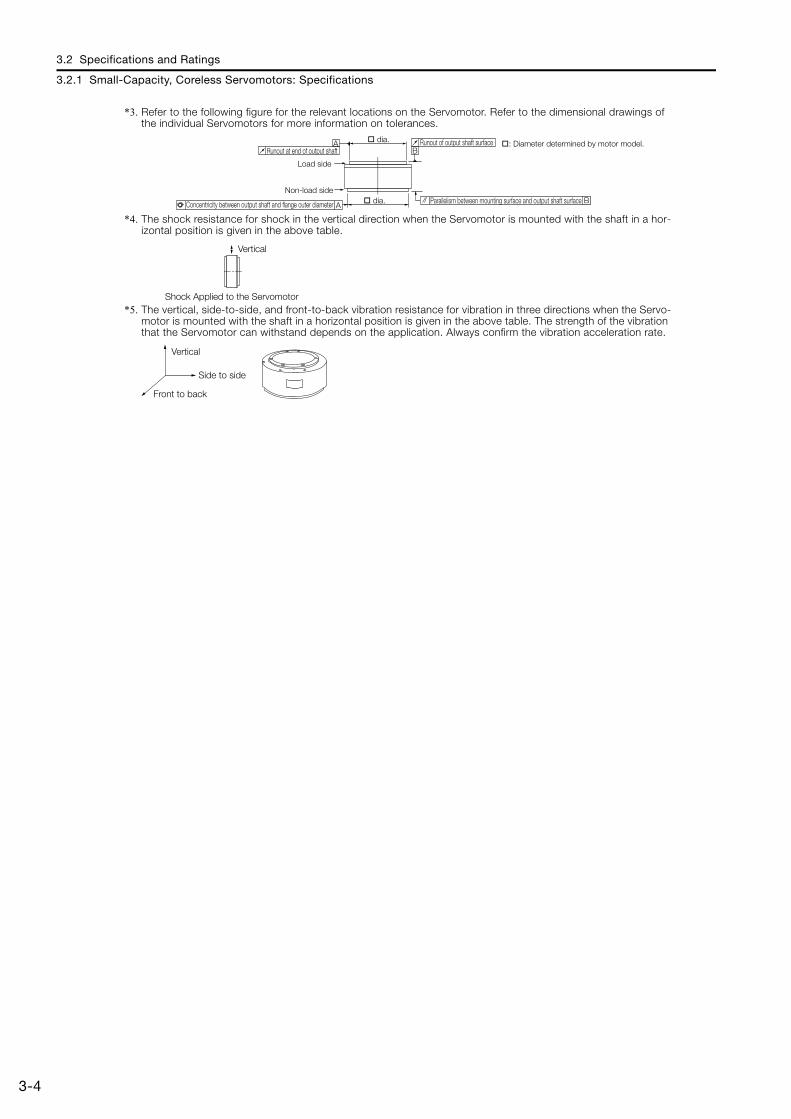
*3. Refer to the following figure for the relevant locations on the Servomotor. Refer to the dimensional drawings of the individual Servomotors for more information on tolerances.
*4. The shock resistance for shock in the vertical direction when the Servomotor is mounted with the shaft in a hor-izontal position is given in the above table.
*5. The vertical, side-to-side, and front-to-back vibration resistance for vibration in three directions when the Servo-motor is mounted with the shaft in a horizontal position is given in the above table. The strength of the vibration that the Servomotor can withstand depends on the application. Always confirm the vibration acceleration rate.
A
AB
B
dia.
dia.
Runout of output shaft surface
Parallelism between mounting surface and output shaft surface
Runout at end of output shaft
Load side
Non-load side
Concentricity between output shaft and flange outer diameter
: Diameter determined by motor model.
Vertical
Shock Applied to the Servomotor
Vertical
Front to back
Side to side
3.2 Specifications and Ratings
3.2.2 Small-Capacity, Coreless Servomotors: Ratings
3-5
3
Spe
cific
atio
ns, R
atin
gs, a
nd E
xter
nal D
imen
sion
s of
SG
MCS
Ser
vom
otors
3.2.2 Small-Capacity, Coreless Servomotors: Ratings
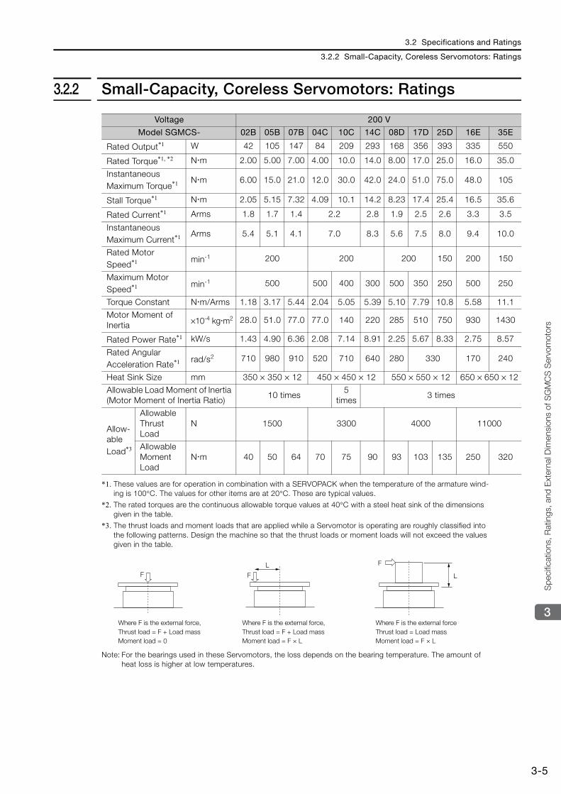
*1. These values are for operation in combination with a SERVOPACK when the temperature of the armature wind-ing is 100°C. The values for other items are at 20°C. These are typical values.
*2. The rated torques are the continuous allowable torque values at 40°C with a steel heat sink of the dimensions given in the table.
*3. The thrust loads and moment loads that are applied while a Servomotor is operating are roughly classified into the following patterns. Design the machine so that the thrust loads or moment loads will not exceed the values given in the table.
Note: For the bearings used in these Servomotors, the loss depends on the bearing temperature. The amount of heat loss is higher at low temperatures.
Voltage 200 V
Model SGMCS- 02B 05B 07B 04C 10C 14C 08D 17D 25D 16E 35E
Rated Output*1 W 42 105 147 84 209 293 168 356 393 335 550
Rated Torque*1, *2 N m 2.00 5.00 7.00 4.00 10.0 14.0 8.00 17.0 25.0 16.0 35.0
Instantaneous Maximum Torque*1 N m 6.00 15.0 21.0 12.0 30.0 42.0 24.0 51.0 75.0 48.0 105
Stall Torque*1 N m 2.05 5.15 7.32 4.09 10.1 14.2 8.23 17.4 25.4 16.5 35.6
Rated Current*1 Arms 1.8 1.7 1.4 2.2 2.8 1.9 2.5 2.6 3.3 3.5
Instantaneous Maximum Current*1 Arms 5.4 5.1 4.1 7.0 8.3 5.6 7.5 8.0 9.4 10.0
Rated Motor Speed*1 min-1 200 200 200 150 200 150
Maximum Motor Speed*1 min-1 500 500 400 300 500 350 250 500 250
Torque Constant N m/Arms 1.18 3.17 5.44 2.04 5.05 5.39 5.10 7.79 10.8 5.58 11.1
Motor Moment of Inertia ×10-4 kg m2 28.0 51.0 77.0 77.0 140 220 285 510 750 930 1430
Rated Power Rate*1 kW/s 1.43 4.90 6.36 2.08 7.14 8.91 2.25 5.67 8.33 2.75 8.57
Rated Angular Acceleration Rate*1 rad/s2 710 980 910 520 710 640 280 330 170 240
Heat Sink Size mm 350 × 350 × 12 450 × 450 × 12 550 × 550 × 12 650 × 650 × 12
Allowable Load Moment of Inertia (Motor Moment of Inertia Ratio)
10 times5
times3 times
Allow-able Load*3
Allowable Thrust Load
N 1500 3300 4000 11000
Allowable Moment Load
N m 40 50 64 70 75 90 93 103 135 250 320
F
F
LF
L
Where F is the external force,Thrust load = F + Load massMoment load = 0
Where F is the external forceThrust load = Load massMoment load = F × L
Where F is the external force,Thrust load = F + Load massMoment load = F × L

3.2 Specifications and Ratings
3.2.3 Small-Capacity, Coreless Servomotors: Torque-Motor Speed Characteristics
3-6
3.2.3 Small-Capacity, Coreless Servomotors: Torque-Motor Speed Characteristics
Note: 1. These values are for operation in combination with a SERVOPACK when the temperature of the armature winding is 100°C. These are typical values.
2. The characteristics in the intermittent duty zone depend on the power supply voltage.
3. If the effective torque is within the allowable range for the rated torque, the Servomotor can be used within the intermittent duty zone.
4. If you use a Servomotor Main Circuit Cable that exceeds 20 m, the intermittent duty zone in the torque-motor speed characteristics will become smaller because the voltage drop increases.
SGMCS-02B
A
00
100
1.5 3.0 4.5 6.0 7.5 9.0
200
300
400
500
B
SGMCS-05B
A
00
100
3 6 9 12 15 18
200
300
400
500
B
SGMCS-07B
A
00
100
5 10 15 20 25 30
200
300
400
500
B
SGMCS-04C
A
00
100
3 6 9 12 15 18
200
300
400
500
B
SGMCS-10C
A
00
100
6 12 18 24 30 36
200
300
400
500
B
SGMCS-14C
A
00
100
10 20 30 40 50 60
200
300
400
500
B100
200
300
400
500SGMCS-08D
00
100
6 12 18 24 30 36
200
300
400
500SGMCS-17D
A
00
12 24 36 48 60 72
B
100
200
300
400
500SGMCS-16E
A
00
100
9 18 27 36 45 54
200
300
400
500
B
SGMCS-35E
A
00
20 40 60 80 100 120
B
SGMCS-25D
A
00
100
15 30 45 60 75 90
200
300
400
500
B
A B
Torque (N·m)
Mot
or s
peed
(min
-1)
Torque (N·m) Torque (N·m)
Torque (N·m)Torque (N·m) Torque (N·m)
Torque (N·m)
Torque (N·m)
Torque (N·m)Torque (N·m)Torque (N·m)
Mot
or s
peed
(min
-1)
Mot
or s
peed
(min
-1)
Mot
or s
peed
(min
-1)
Mot
or s
peed
(min
-1)
Mot
or s
peed
(min
-1)
Mot
or s
peed
(min
-1)
Mot
or s
peed
(min
-1)
Mot
or s
peed
(min
-1)
Mot
or s
peed
(min
-1)
Mot
or s
peed
(min
-1)
A :
B :Continuous duty zone (solid lines): With three-phase 200-V input
(dotted lines): With single-phase 100-V inputIntermittent duty zone
3.2 Specifications and Ratings
3.2.4 Small-Capacity, Coreless Servomotors: Servomotor Overload Protection Characteristics
3-7
3
Spe
cific
atio
ns, R
atin
gs, a
nd E
xter
nal D
imen
sion
s of
SG
MCS
Ser
vom
otors
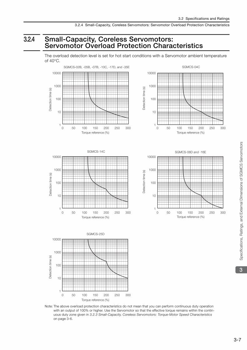
3.2.4 Small-Capacity, Coreless Servomotors: Servomotor Overload Protection CharacteristicsThe overload detection level is set for hot start conditions with a Servomotor ambient temperature of 40°C.
Note: The above overload protection characteristics do not mean that you can perform continuous duty operation with an output of 100% or higher. Use the Servomotor so that the effective torque remains within the contin-uous duty zone given in 3.2.3 Small-Capacity, Coreless Servomotors: Torque-Motor Speed Characteristics on page 3-6.
SGMCS-02B, -05B, -07B, -10C, -17D, and -35E
SGMCS-08D and -16E
Det
ectio
n tim
e (s
)
Torque reference (%)
Det
ectio
n tim
e (s
)
Det
ectio
n tim
e (s
)D
etec
tion
time
(s)
Torque reference (%)
Torque reference (%) Torque reference (%)
Torque reference (%)
0 50 100 150 200 250 300
10000
1000
100
10
1
SGMCS-04C
0 50 100 150 200 250 300
10000
1000
100
10
1
SGMCS-14C
0 50 100 150 200 250 300
10000
1000
100
10
1
SGMCS-25D
0 50 100 150 200 250 300
10000
1000
100
10
1
0 50 100 150 200 250 300
10000
1000
100
10
1
Det
ectio
n tim
e (s
)
3.2 Specifications and Ratings
3.2.5 Medium-Capacity Servomotors with Cores: Specifications
3-8
3.2.5 Medium-Capacity Servomotors with Cores: Specifications
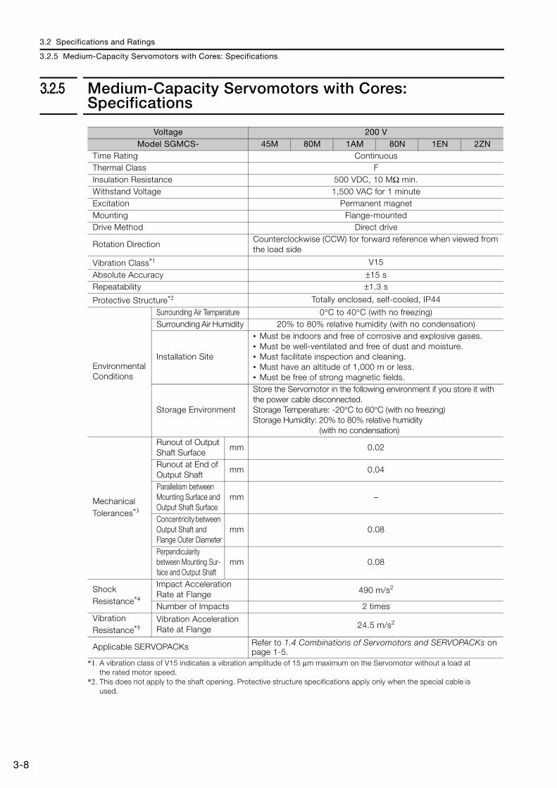
*1. A vibration class of V15 indicates a vibration amplitude of 15 μm maximum on the Servomotor without a load at the rated motor speed.
*2. This does not apply to the shaft opening. Protective structure specifications apply only when the special cable is used.
Voltage 200 VModel SGMCS- 45M 80M 1AM 80N 1EN 2ZN
Time Rating Continuous Thermal Class FInsulation Resistance 500 VDC, 10 MΩ min. Withstand Voltage 1,500 VAC for 1 minute Excitation Permanent magnet Mounting Flange-mounted Drive Method Direct drive
Rotation Direction Counterclockwise (CCW) for forward reference when viewed from the load side
Vibration Class*1 V15
Absolute Accuracy ±15 s Repeatability ±1.3 s
Protective Structure*2 Totally enclosed, self-cooled, IP44
Environmental Conditions
Surrounding Air Temperature 0°C to 40°C (with no freezing) Surrounding Air Humidity 20% to 80% relative humidity (with no condensation)
Installation Site
• Must be indoors and free of corrosive and explosive gases.• Must be well-ventilated and free of dust and moisture.• Must facilitate inspection and cleaning.• Must have an altitude of 1,000 m or less.• Must be free of strong magnetic fields.
Storage Environment
Store the Servomotor in the following environment if you store it with the power cable disconnected.Storage Temperature: -20°C to 60°C (with no freezing) Storage Humidity: 20% to 80% relative humidity
(with no condensation)
Mechanical Tolerances*3
Runout of Output Shaft Surface
mm 0.02
Runout at End of Output Shaft
mm 0.04
Parallelism between Mounting Surface and Output Shaft Surface
mm −
Concentricity between Output Shaft and Flange Outer Diameter
mm 0.08
Perpendicularity between Mounting Sur-face and Output Shaft
mm 0.08
Shock Resistance*4
Impact Acceleration Rate at Flange 490 m/s2
Number of Impacts 2 times Vibration Resistance*5
Vibration Acceleration Rate at Flange 24.5 m/s2
Applicable SERVOPACKs Refer to 1.4 Combinations of Servomotors and SERVOPACKs on page 1-5.
3.2 Specifications and Ratings
3.2.5 Medium-Capacity Servomotors with Cores: Specifications
3-9
3
Spe
cific
atio
ns, R
atin
gs, a
nd E
xter
nal D
imen
sion
s of
SG
MCS
Ser
vom
otors
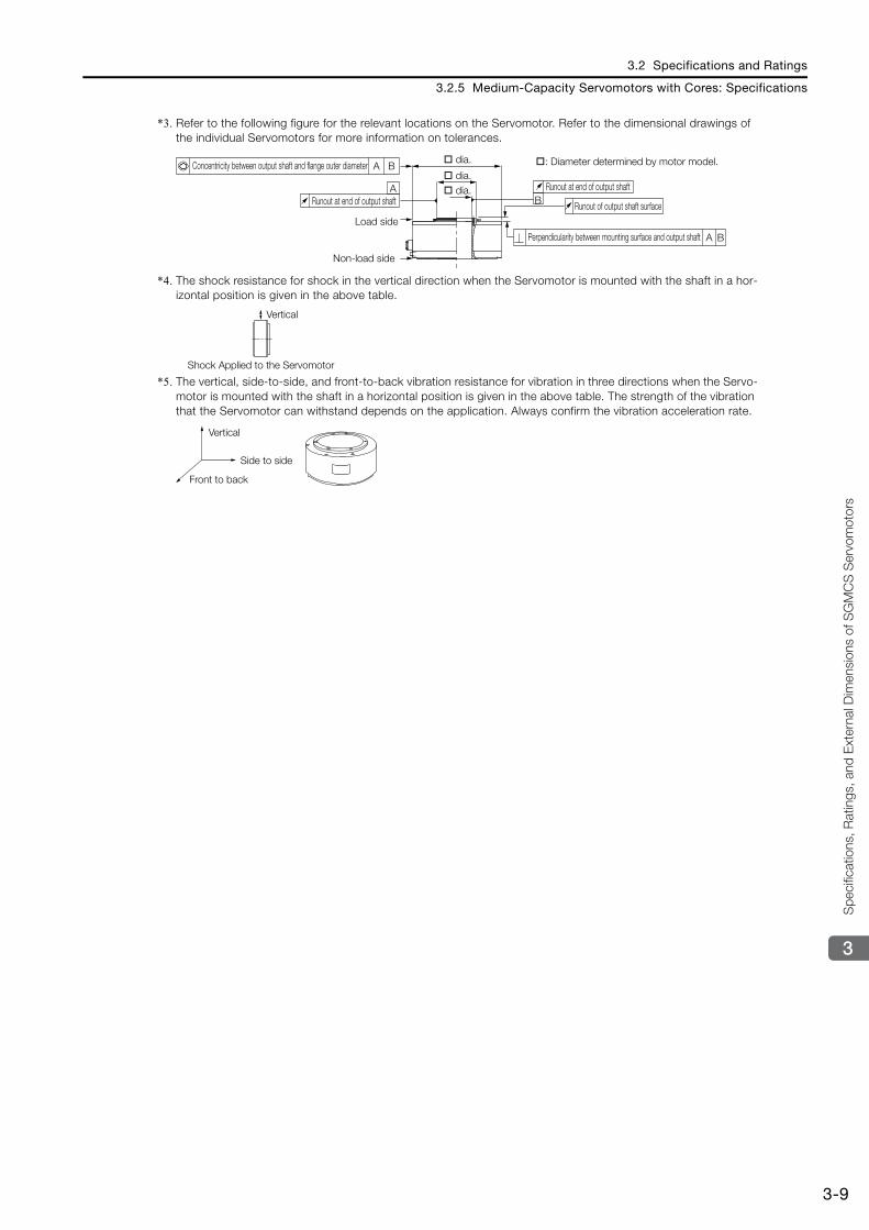
*3. Refer to the following figure for the relevant locations on the Servomotor. Refer to the dimensional drawings of the individual Servomotors for more information on tolerances.
*4. The shock resistance for shock in the vertical direction when the Servomotor is mounted with the shaft in a hor-izontal position is given in the above table.
*5. The vertical, side-to-side, and front-to-back vibration resistance for vibration in three directions when the Servo-motor is mounted with the shaft in a horizontal position is given in the above table. The strength of the vibration that the Servomotor can withstand depends on the application. Always confirm the vibration acceleration rate.
B
A
A
A B
B
Runout at end of output shaft
Runout of output shaft surface
Perpendicularity between mounting surface and output shaft
Concentricity between output shaft and flange outer diameter
Runout at end of output shaft
Load side
Non-load side
dia. : Diameter determined by motor model. dia. dia.
Vertical
Shock Applied to the Servomotor
Side to side
Front to back
Vertical
3.2 Specifications and Ratings
3.2.6 Medium-Capacity Servomotors with Cores: Ratings
3-10
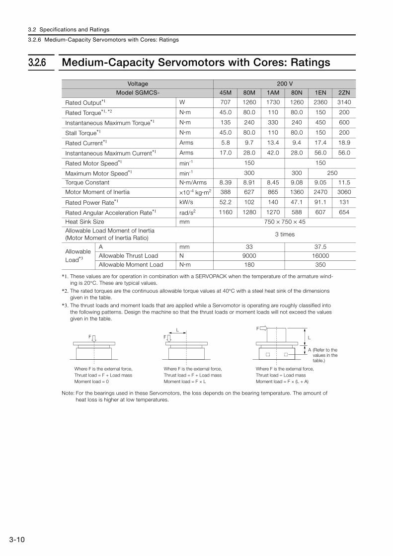
3.2.6 Medium-Capacity Servomotors with Cores: Ratings
*1. These values are for operation in combination with a SERVOPACK when the temperature of the armature wind-ing is 20°C. These are typical values.
*2. The rated torques are the continuous allowable torque values at 40°C with a steel heat sink of the dimensions given in the table.
*3. The thrust loads and moment loads that are applied while a Servomotor is operating are roughly classified into the following patterns. Design the machine so that the thrust loads or moment loads will not exceed the values given in the table.
Note: For the bearings used in these Servomotors, the loss depends on the bearing temperature. The amount of heat loss is higher at low temperatures.
Voltage 200 V
Model SGMCS- 45M 80M 1AM 80N 1EN 2ZN
Rated Output*1 W 707 1260 1730 1260 2360 3140
Rated Torque*1, *2 N m 45.0 80.0 110 80.0 150 200
Instantaneous Maximum Torque*1 N m 135 240 330 240 450 600
Stall Torque*1 N m 45.0 80.0 110 80.0 150 200
Rated Current*1 Arms 5.8 9.7 13.4 9.4 17.4 18.9
Instantaneous Maximum Current*1 Arms 17.0 28.0 42.0 28.0 56.0 56.0
Rated Motor Speed*1 min-1 150 150
Maximum Motor Speed*1 min-1 300 300 250
Torque Constant N m/Arms 8.39 8.91 8.45 9.08 9.05 11.5
Motor Moment of Inertia ×10-4 kg m2 388 627 865 1360 2470 3060
Rated Power Rate*1 kW/s 52.2 102 140 47.1 91.1 131
Rated Angular Acceleration Rate*1 rad/s2 1160 1280 1270 588 607 654
Heat Sink Size mm 750 × 750 × 45
Allowable Load Moment of Inertia (Motor Moment of Inertia Ratio)
3 times
Allowable Load*3
A mm 33 37.5
Allowable Thrust Load N 9000 16000
Allowable Moment Load N m 180 350
F F
L F
L
Where F is the external force,Thrust load = F + Load mass Moment load = 0
Where F is the external force,Thrust load = F + Load massMoment load = F × L
Where F is the external force,Thrust load = Load massMoment load = F × (L + A)
A (Refer to the values in the table.)
3.2 Specifications and Ratings
3.2.7 Medium-Capacity Servomotors with Cores: Torque-Motor Speed Characteristics
3-11
3
Spe
cific
atio
ns, R
atin
gs, a
nd E
xter
nal D
imen
sion
s of
SG
MCS
Ser
vom
otors
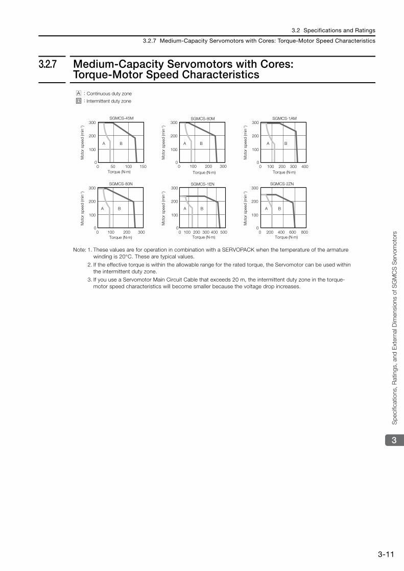
3.2.7 Medium-Capacity Servomotors with Cores: Torque-Motor Speed Characteristics
Note: 1. These values are for operation in combination with a SERVOPACK when the temperature of the armature winding is 20°C. These are typical values.
2. If the effective torque is within the allowable range for the rated torque, the Servomotor can be used within the intermittent duty zone.
3. If you use a Servomotor Main Circuit Cable that exceeds 20 m, the intermittent duty zone in the torque-motor speed characteristics will become smaller because the voltage drop increases.
A
0 50 100 1500
100
200
300
B A
0 100 200 3000
100
200
300
B
SGMCS-45M SGMCS-80M
A
0 100 200 300 4000
100
200
300
B
A
0 100 200 3000
100
200
300
B
SGMCS-1AM
SGMCS-80N
A
0 100 200 300 400 5000
100
200
300
B A
0 200 400 600 8000
100
200
300
B
SGMCS-1EN SGMCS-2ZN
A :
B :Continuous duty zone
Intermittent duty zone
Mot
or s
peed
(min
-1)
Torque (N⋅m) Torque (N⋅m) Torque (N⋅m)
Torque (N⋅m)Torque (N⋅m)Torque (N⋅m)
Mot
or s
peed
(min
-1)
Mot
or s
peed
(min
-1)
Mot
or s
peed
(min
-1)
Mot
or s
peed
(min
-1)
Mot
or s
peed
(min
-1)
3.2 Specifications and Ratings
3.2.8 Medium-Capacity Servomotors with Cores: Servomotor Overload Protection Characteristics
3-12
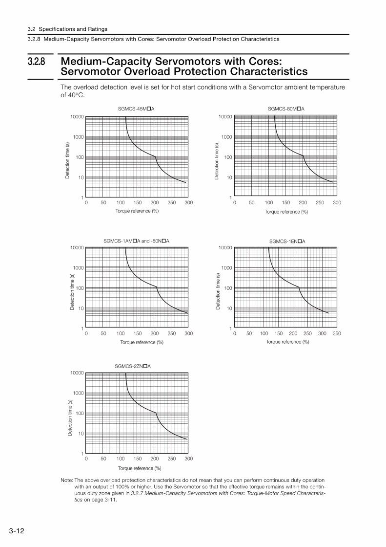
3.2.8 Medium-Capacity Servomotors with Cores: Servomotor Overload Protection CharacteristicsThe overload detection level is set for hot start conditions with a Servomotor ambient temperature of 40°C.
Note: The above overload protection characteristics do not mean that you can perform continuous duty operation with an output of 100% or higher. Use the Servomotor so that the effective torque remains within the contin-uous duty zone given in 3.2.7 Medium-Capacity Servomotors with Cores: Torque-Motor Speed Characteris-tics on page 3-11.
SGMCS-45M A SGMCS-80M A
SGMCS-1AM A and -80N A
SGMCS-2ZN A
SGMCS-1EN A
Det
ectio
n tim
e (s
)
Torque reference (%)D
etec
tion
time
(s)
Torque reference (%)
Det
ectio
n tim
e (s
)
Torque reference (%)
Det
ectio
n tim
e (s
)
Torque reference (%)
Det
ectio
n tim
e (s
)
Torque reference (%)
10000
1000
100
10
1
10000
1000
100
10
1
10000
1000
100
10
1
10000
1000
100
10
1
10000
1000
100
10
1
0 50 100 150 200 250 300 0 50 100 150 200 250 300
0 50 100 150 200 250 300
0 50 100 150 200 250 300
0 50 100 150 200 250 300 350
3.2 Specifications and Ratings
3.2.9 Load Moment of Inertia
3-13
3
Spe
cific
atio
ns, R
atin
gs, a
nd E
xter
nal D
imen
sion
s of
SG
MCS
Ser
vom
otors
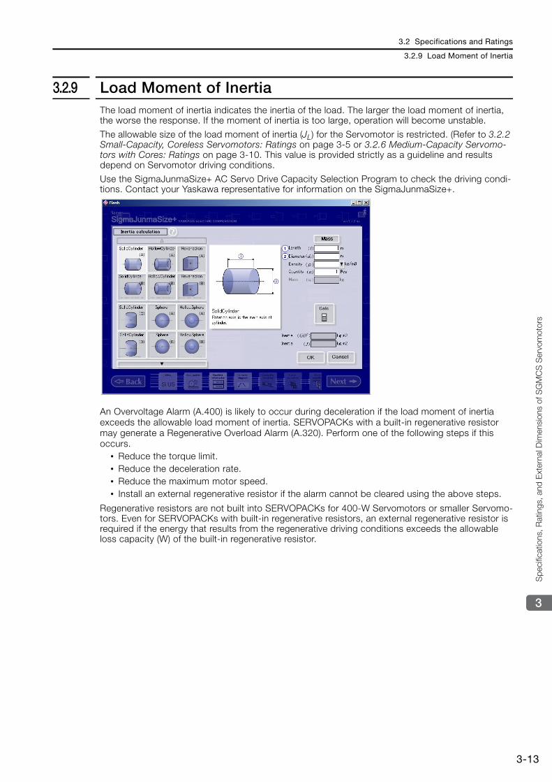
3.2.9 Load Moment of InertiaThe load moment of inertia indicates the inertia of the load. The larger the load moment of inertia, the worse the response. If the moment of inertia is too large, operation will become unstable.
The allowable size of the load moment of inertia (JL) for the Servomotor is restricted. (Refer to 3.2.2 Small-Capacity, Coreless Servomotors: Ratings on page 3-5 or 3.2.6 Medium-Capacity Servomo-tors with Cores: Ratings on page 3-10. This value is provided strictly as a guideline and results depend on Servomotor driving conditions.
Use the SigmaJunmaSize+ AC Servo Drive Capacity Selection Program to check the driving condi-tions. Contact your Yaskawa representative for information on the SigmaJunmaSize+.
An Overvoltage Alarm (A.400) is likely to occur during deceleration if the load moment of inertia exceeds the allowable load moment of inertia. SERVOPACKs with a built-in regenerative resistor may generate a Regenerative Overload Alarm (A.320). Perform one of the following steps if this occurs.
• Reduce the torque limit. • Reduce the deceleration rate. • Reduce the maximum motor speed. • Install an external regenerative resistor if the alarm cannot be cleared using the above steps.
Regenerative resistors are not built into SERVOPACKs for 400-W Servomotors or smaller Servomo-tors. Even for SERVOPACKs with built-in regenerative resistors, an external regenerative resistor is required if the energy that results from the regenerative driving conditions exceeds the allowable loss capacity (W) of the built-in regenerative resistor.
3.2 Specifications and Ratings
3.2.10 Allowable Load Moment of Inertia Scaling Factor for SERVOPACKs without Built-in Regenerative Resistors
3-14
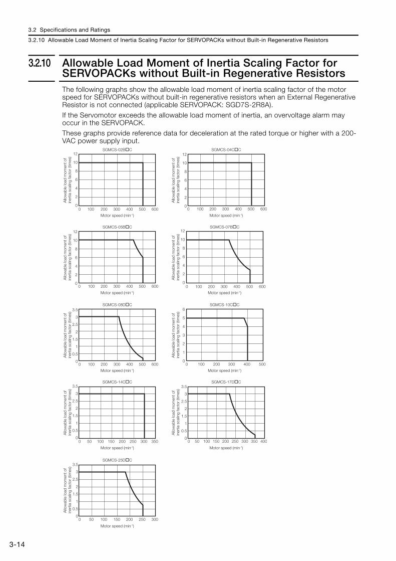
3.2.10 Allowable Load Moment of Inertia Scaling Factor for SERVOPACKs without Built-in Regenerative ResistorsThe following graphs show the allowable load moment of inertia scaling factor of the motor speed for SERVOPACKs without built-in regenerative resistors when an External Regenerative Resistor is not connected (applicable SERVOPACK: SGD7S-2R8A).
If the Servomotor exceeds the allowable load moment of inertia, an overvoltage alarm may occur in the SERVOPACK.
These graphs provide reference data for deceleration at the rated torque or higher with a 200-VAC power supply input.
Motor speed (min-1)
Motor speed (min-1)Motor speed (min-1)
Motor speed (min-1)Motor speed (min-1)
Motor speed (min-1)
Motor speed (min-1)
Allo
wab
le lo
ad m
omen
t of
iner
tia s
calin
g fa
ctor
(tim
es)
0
2
4
6
8
10
12
0 100 200 300 400 500 600
Motor speed (min-1)
SGMCS-02B C
0
2
4
6
8
10
12
0 100 200 300 400 500 600
SGMCS-04C C
0
2
4
6
8
10
12
0 100 200 300 400 500 600
SGMCS-07B C
0
0.5
1
1.5
2
2.5
3
3.5
0 100 200 300 400 500 600
SGMCS-08D C
0
1
2
3
4
5
6
0 100 200 300 400 500
SGMCS-10C C
0
0.5
1
1.5
2
2.5
3
3.5
0 50 100 150 200 250 300 350
SGMCS-14C C
0
0.5
1
1.5
2
2.5
3
3.5
0 50 100 150 200 250 300 350 400
SGMCS-17D C
0
0.5
1
1.5
2
2.5
3
3.5
0 50 100 150 200 250 300
SGMCS-25D C
Allo
wab
le lo
ad m
omen
t of
iner
tia s
calin
g fa
ctor
(tim
es)
Motor speed (min-1)
0
2
4
6
8
10
12
0 100 200 300 400 500 600
SGMCS-05B C
Allo
wab
le lo
ad m
omen
t of
iner
tia s
calin
g fa
ctor
(tim
es)
Allo
wab
le lo
ad m
omen
t of
iner
tia s
calin
g fa
ctor
(tim
es)
Allo
wab
le lo
ad m
omen
t of
iner
tia s
calin
g fa
ctor
(tim
es)
Allo
wab
le lo
ad m
omen
t of
iner
tia s
calin
g fa
ctor
(tim
es)
Allo
wab
le lo
ad m
omen
t of
iner
tia s
calin
g fa
ctor
(tim
es)
Allo
wab
le lo
ad m
omen
t of
iner
tia s
calin
g fa
ctor
(tim
es)
Allo
wab
le lo
ad m
omen
t of
iner
tia s
calin
g fa
ctor
(tim
es)
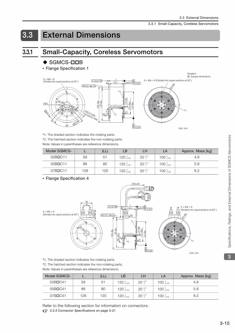
3.3 External Dimensions
3.3.1 Small-Capacity, Coreless Servomotors
3-15
3
Spe
cific
atio
ns, R
atin
gs, a
nd E
xter
nal D
imen
sion
s of
SG
MCS
Ser
vom
otors
3.3 External Dimensions
3.3.1 Small-Capacity, Coreless Servomotors
SGMCS- B• Flange Specification 1
*1. The shaded section indicates the rotating parts.
*2. The hatched section indicates the non-rotating parts.
Note: Values in parentheses are reference dimensions.
• Flange Specification 4
*1. The shaded section indicates the rotating parts.
*2. The hatched section indicates the non-rotating parts.
Note: Values in parentheses are reference dimensions.
Refer to the following section for information on connectors. 3.3.3 Connector Specifications on page 3-21
Model SGMCS- L (LL) LB LH LA Approx. Mass [kg]
02B C11 59 51 120 20 100 4.8
05B C11 88 80 120 20 100 5.8
07B C11 128 120 120 20 100 8.2
Model SGMCS- L (LL) LB LH LA Approx. Mass [kg]
02B C41 59 51 120 20 100 4.8
05B C41 88 80 120 20 100 5.8
07B C41 128 120 120 20 100 8.2
0.04A
B0.02
A
0.07 B4 (LL)
L
*1
*1
*2
4±0.9
(9)(1)
90°
R26
25.4
23.4
6 × M4 × 8 (Divided into equal sections at 60°.)
0.07 dia.
6 × M4 × 8 (Divided into equal sections at 60°.)
Unit: mm
(0.5: bolt section)
135
dia.
LH d
ia.
(70
dia.
)
R40.5 max. connector area
LB d
ia.
LA d
ia.
90 d
ia.
90 dia.
Notation: Square dimensions
0-0.035
+0.4 0
0-0.035
0-0.035
+0.4 0
0-0.035
0-0.035
+0.4 0
0-0.035
4
20
(LL)L
(1)0.1
(35)
300±50
4±0.93050
(22)
10
0.07 B
A
B0.02
A0.04
*1
*1
*2
6 × M4 × 8 (Divided into equal sections at 60°.)
6 × M4 × 8 (Divided into equal sections at 60°.)
0.07 dia.
Unit: mm
135
dia.
(70
dia.
)
(80
dia.
)
90 dia.
(0.5: bolt section)LB d
ia.
LA d
ia.
LH d
ia.
90 d
ia.
0-0.035
+0.4 0
0-0.035
0-0.035
+0.4 0
0-0.035
0-0.035
+0.4 0
0-0.035
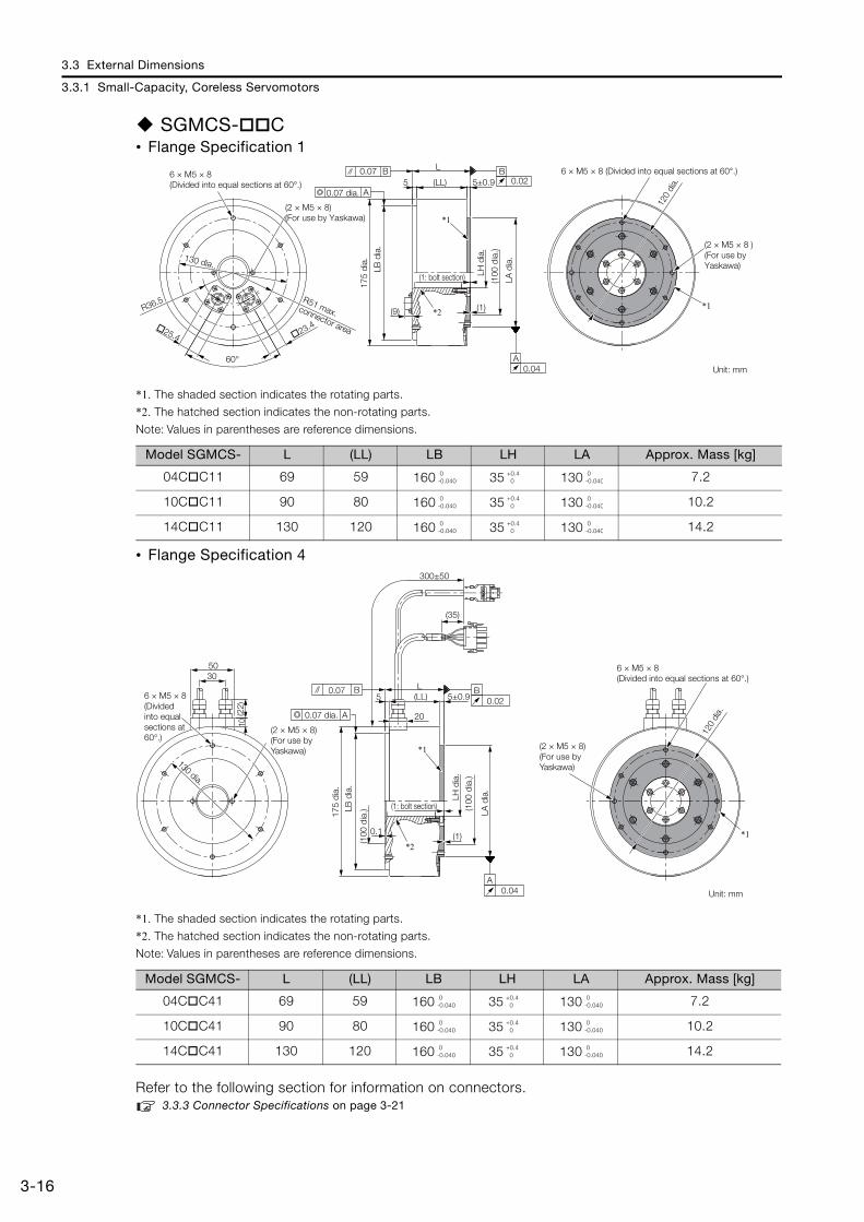
3.3 External Dimensions
3.3.1 Small-Capacity, Coreless Servomotors
3-16
SGMCS- C• Flange Specification 1
*1. The shaded section indicates the rotating parts.
*2. The hatched section indicates the non-rotating parts.
Note: Values in parentheses are reference dimensions.
• Flange Specification 4
*1. The shaded section indicates the rotating parts.
*2. The hatched section indicates the non-rotating parts.
Note: Values in parentheses are reference dimensions.
Refer to the following section for information on connectors. 3.3.3 Connector Specifications on page 3-21
Model SGMCS- L (LL) LB LH LA Approx. Mass [kg]
04C C11 69 59 160 35 130 7.2
10C C11 90 80 160 35 130 10.2
14C C11 130 120 160 35 130 14.2
Model SGMCS- L (LL) LB LH LA Approx. Mass [kg]
04C C41 69 59 160 35 130 7.2
10C C41 90 80 160 35 130 10.2
14C C41 130 120 160 35 130 14.2
60°
5 (LL)
L
5±0.9
(9)
*1
*2 (1) *1R36.5
25.4 23.4
B0.02
A
0.07
0.04A
B6 × M5 × 8 (Divided into equal sections at 60°.)
0.07 dia.
(2 × M5 × 8) (For use by Yaskawa)
6 × M5 × 8 (Divided into equal sections at 60°.)
(2 × M5 × 8 )(For use by Yaskawa)
Unit: mm
(1: bolt section)
175
dia.
LB d
ia.
(100
dia
.)
LA d
ia.130 dia.
120
dia.
R51 max. connector area
LH d
ia.
0-0.040
+0.4 0
0-0.040
0-0.040
+0.4 0
0-0.040
0-0.040
+0.4 0
0-0.040
5
20
(LL)L
0.1
(35)
(1)
3050
(22)
10
0.07 B
A
B0.02
A0.04
300±50
5±0.9
*1
*2*1
6 × M5 × 8 (Divided into equal sections at 60°.)
130 dia.
(2 × M5 × 8) (For use by Yaskawa) (2 × M5 × 8)
(For use by Yaskawa)
Unit: mm
6 × M5 × 8 (Divided into equal sections at 60°.)
(1: bolt section)
175
dia.
(100
dia
.) (100
dia
.)
0.07 dia.
LB d
ia.
LA d
ia.
120
dia.
LH d
ia.
0-0.040
+0.4 0
0-0.040
0-0.040
+0.4 0
0-0.040
0-0.040
+0.4 0
0-0.040
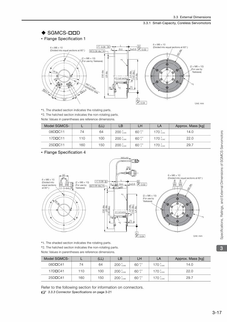
3.3 External Dimensions
3.3.1 Small-Capacity, Coreless Servomotors
3-17
3
Spe
cific
atio
ns, R
atin
gs, a
nd E
xter
nal D
imen
sion
s of
SG
MCS
Ser
vom
otors
SGMCS- D• Flange Specification 1
*1. The shaded section indicates the rotating parts.
*2. The hatched section indicates the non-rotating parts.
Note: Values in parentheses are reference dimensions.
• Flange Specification 4
*1. The shaded section indicates the rotating parts.
*2. The hatched section indicates the non-rotating parts.
Note: Values in parentheses are reference dimensions.
Refer to the following section for information on connectors. 3.3.3 Connector Specifications on page 3-21
Model SGMCS- L (LL) LB LH LA Approx. Mass [kg]
08D C11 74 64 200 60 170 14.0
17D C11 110 100 200 60 170 22.0
25D C11 160 150 200 60 170 29.7
Model SGMCS- L (LL) LB LH LA Approx. Mass [kg]
08D C41 74 64 200 60 170 14.0
17D C41 110 100 200 60 170 22.0
25D C41 160 150 200 60 170 29.7
(LL)
L
5 5±0.9
60°
R53
*1
*2(9) (1)
25.4 23.4
A
0.08 B B0.02
0.04A
*1
6 × M6 × 10 (Divided into equal sections at 60°.)
160 dia.
R67.5 max. connector area
(2 × M6 × 10)(For use by Yaskawa)
6 × M6 × 10 (Divided into equal sections at 60°.)
(2 × M6 × 10) (For use by Yaskawa)
Unit: mm
160
dia.
(0.5: bolt section)230
dia.
(140
dia
.)
0.08 dia.
LB d
ia.
LA d
ia.
LH d
ia.
0-0.046
+0.4 0
0-0.040
0-0.046
+0.4 0
0-0.040
0-0.046
+0.4 0
0-0.040
520
(LL)
L
0.1
(1)
5±0.9
300±50
(35)
3050
(22)
10
*1
*1
*2
B0.02
0.08 B
A
A0.04
6 × M6 × 10 (Divided into equal sections at 60°.)
160 dia.
(2 × M6 × 10) (For use by Yaskawa)
(2 × M6 × 10) (For use by Yaskawa)
6 × M6 × 10 (Divided into equal sections at 60°.)
Unit: mm
160
dia.0.08 dia.
(0.5: bolt section)
(140
dia
.)
(140
dia
.)
230
dia.
LB d
ia.
LA d
ia.
LH d
ia.
0-0.046
+0.4 0
0-0.040
0-0.046
+0.4 0
0-0.040
0-0.046
+0.4 0
0-0.040
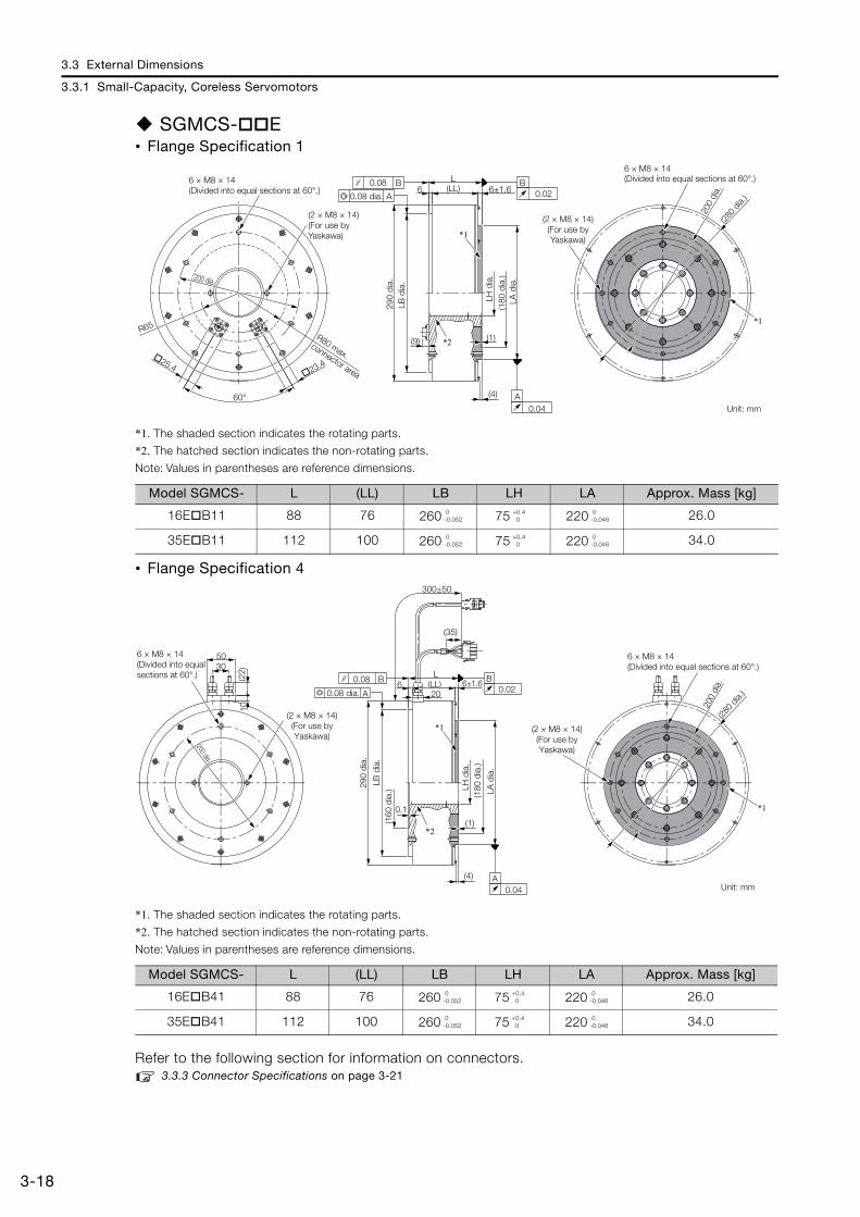
3.3 External Dimensions
3.3.1 Small-Capacity, Coreless Servomotors
3-18
SGMCS- E• Flange Specification 1
*1. The shaded section indicates the rotating parts.
*2. The hatched section indicates the non-rotating parts.
Note: Values in parentheses are reference dimensions.
• Flange Specification 4
*1. The shaded section indicates the rotating parts.
*2. The hatched section indicates the non-rotating parts.
Note: Values in parentheses are reference dimensions.
Refer to the following section for information on connectors. 3.3.3 Connector Specifications on page 3-21
Model SGMCS- L (LL) LB LH LA Approx. Mass [kg]
16E B11 88 76 260 75 220 26.0
35E B11 112 100 260 75 220 34.0
Model SGMCS- L (LL) LB LH LA Approx. Mass [kg]
16E B41 88 76 260 75 220 26.0
35E B41 112 100 260 75 220 34.0
60°
*2
*1
R65
(LL)L
6
(9) (1)
(4)
A
0.08 B B0.02
0.04A
25.4 23.4
200 dia.
6±1.6
*1
6 × M8 × 14 (Divided into equal sections at 60°.)
290
dia.
(2 × M8 × 14) (For use by Yaskawa)
(2 × M8 × 14) (For use by Yaskawa)
6 × M8 × 14 (Divided into equal sections at 60°.)
Unit: mm
200
dia.
(280
dia.)
(180
dia
.)
0.08 dia.
R80 max. connector area
LB d
ia.
LA d
ia.
LH d
ia.
0-0.052
+0.4 0
0-0.046
0-0.052
+0.4 0
0-0.046
300±50
(35)
6 (LL)L
0.1
(1)
(4)
*1
*1
*2
3050
(22)
10
0.08 B
A
B0.02
A0.04
206±1.6
(2 × M8 × 14) (For use by Yaskawa)
(160
dia
.)
200
dia.
(280
dia.)
(180
dia
.)
290
dia.
0.08 dia.
(2 × M8 × 14) (For use by Yaskawa)
6 × M8 × 14 (Divided into equal sections at 60°.)
Unit: mm
200 dia.6 × M8 × 14 (Divided into equal sections at 60°.)
LB d
ia.
LA d
ia.
LH d
ia.
0-0.052
+0.4 0
0-0.046
0-0.052
+0.4 0
0-0.046
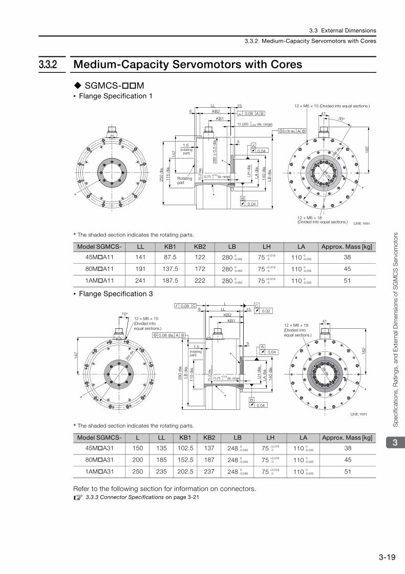
3.3 External Dimensions
3.3.2 Medium-Capacity Servomotors with Cores
3-19
3
Spe
cific
atio
ns, R
atin
gs, a
nd E
xter
nal D
imen
sion
s of
SG
MCS
Ser
vom
otors
3.3.2 Medium-Capacity Servomotors with Cores
SGMCS- M• Flange Specification 1
* The shaded section indicates the rotating parts.
• Flange Specification 3
* The shaded section indicates the rotating parts.
Refer to the following section for information on connectors. 3.3.3 Connector Specifications on page 3-21
Model SGMCS- LL KB1 KB2 LB LH LA Approx. Mass [kg]
45M A11 141 87.5 122 280 75 110 38
80M A11 191 137.5 172 280 75 110 45
1AM A11 241 187.5 222 280 75 110 51
Model SGMCS- L LL KB1 KB2 LB LH LA Approx. Mass [kg]
45M A31 150 135 102.5 137 248 75 110 38
80M A31 200 185 152.5 187 248 75 110 45
1AM A31 250 235 202.5 237 248 75 110 51
A
15
147 18
2
41
0.04
0.04
B
A B
0.08 A B30°
KB2
KB1
LL6
51.5
*
*
**
115
dia.
75.2
dia
.
280
± 0.
5 di
a.
140
dia.
(rotating part)
Rotating part
15 (280 dia. range)
0.08 dia.
12 × M6 × 15 (Divided into equal sections.)
12 × M6 × 18 (Divided into equal sections.) Unit: mm
88 dia.
264
dia.
250
dia.
LB d
ia.
LH d
ia.
LA d
ia.
0-0.052
15 (75 dia. range)+0.019 0
0-0.052
+0.019 0
0-0.035
0-0.052
+0.019 0
0-0.035
0-0.052
+0.019 0
0-0.035
5
182
15LL6KB2
KB1
L
41
1.5
0.08 C
*
*
A B
10°
147
C0.02
A0.04
B0.04
*
*
12 × M6 × 15 (Divided into equal sections.)
264
dia.
0.08 dia.
(rotating part)
12 × M6 × 18 (Divided into equal sections.)
88 dia.
Unit: mm
115
dia.
75.2
dia
.
140
dia.
280
dia.
LB d
ia.
LH d
ia.
LA d
ia.
15 (75 dia. range)+0.019 0
0-0.046
+0.019 0
0-0.035
0-0.046
+0.019 0
0-0.035
0-0.046
+0.019 0
0-0.035
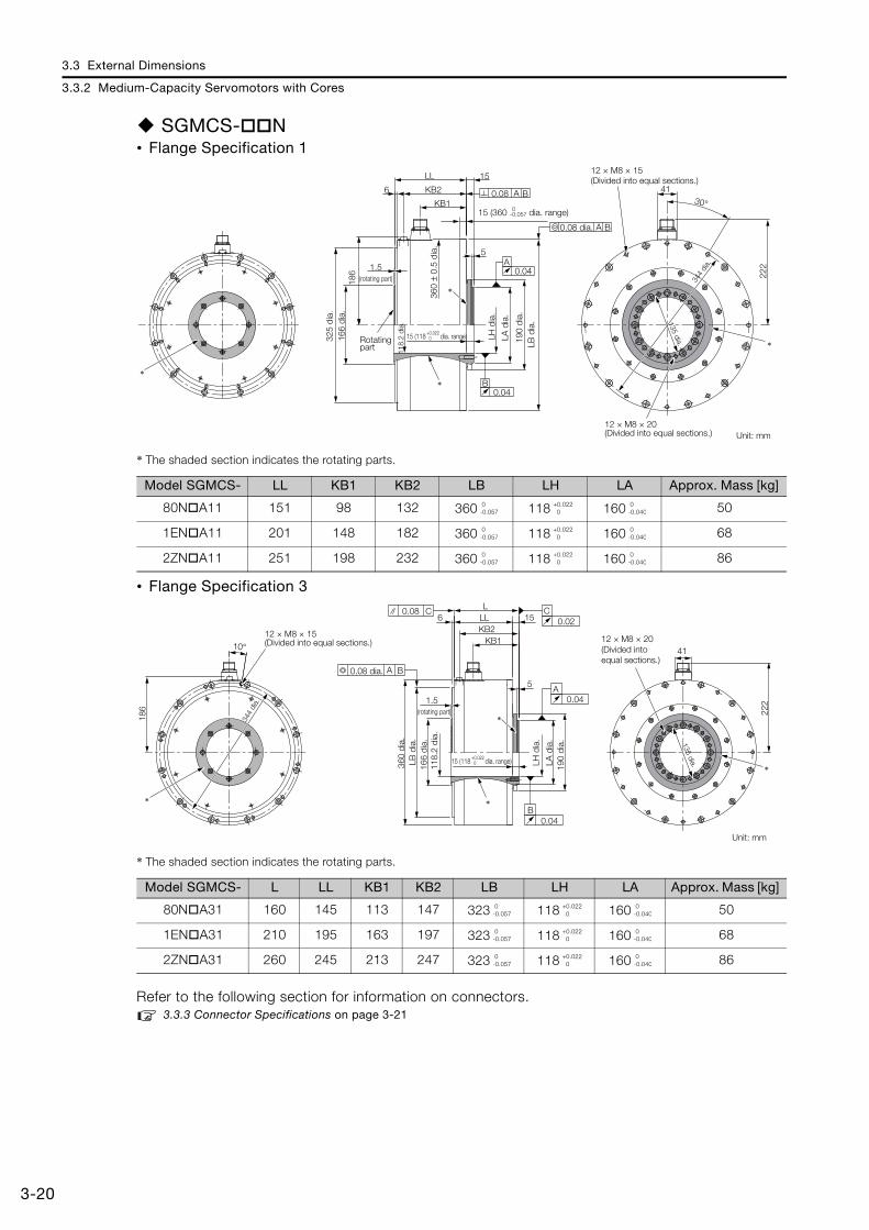
3.3 External Dimensions
3.3.2 Medium-Capacity Servomotors with Cores
3-20
SGMCS- N• Flange Specification 1
* The shaded section indicates the rotating parts.
• Flange Specification 3
* The shaded section indicates the rotating parts.
Refer to the following section for information on connectors. 3.3.3 Connector Specifications on page 3-21
Model SGMCS- LL KB1 KB2 LB LH LA Approx. Mass [kg]
80N A11 151 98 132 360 118 160 50
1EN A11 201 148 182 360 118 160 68
2ZN A11 251 198 232 360 118 160 86
Model SGMCS- L LL KB1 KB2 LB LH LA Approx. Mass [kg]
80N A31 160 145 113 147 323 118 160 50
1EN A31 210 195 163 197 323 118 160 68
2ZN A31 260 245 213 247 323 118 160 86
A
30°
15
0.04
0.04
B
A B
0.08 A B
222
41
186
KB2
KB1
5
LL
6
1.5
*
*
*
*
325
dia.
166
dia.
118.
2 di
a.
190
dia.
360
± 0.
5 di
a.
Rotating part
(rotating part)
0.08 dia.
344
dia.
12 × M8 × 15 (Divided into equal sections.)
12 × M8 × 20 (Divided into equal sections.)
135 dia.
Unit: mm
LB d
ia.
LA d
ia.
LH d
ia.
15 (360 dia. range) 0-0.057
15 (118 dia. range)+0.022 0
0-0.057
+0.022 0
0-0.040
0-0.057
+0.022 0
0-0.040
0-0.057
+0.022 0
0-0.040
10°
222
41
1.5
5
LL 156KB2
KB1
L
186
*
*
0.08 C C0.02
B0.04
A0.04
A B
*
*
12 × M8 × 15 (Divided into equal sections.)
360
dia.
118.
2 di
a.
190
dia.
166
dia.
344
dia.
0.08 dia.
12 × M8 × 20 (Divided into equal sections.)
135 dia.
(rotating part)
Unit: mm
LB d
ia.
LA d
ia.
LH d
ia.
15 (118 dia. range)+0.022 0
0-0.057
+0.022 0
0-0.040
0-0.057
+0.022 0
0-0.040
0-0.057
+0.022 0
0-0.040
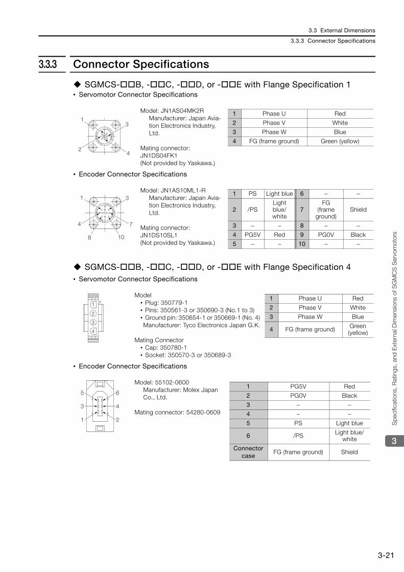
3.3 External Dimensions
3.3.3 Connector Specifications
3-21
3
Spe
cific
atio
ns, R
atin
gs, a
nd E
xter
nal D
imen
sion
s of
SG
MCS
Ser
vom
otors
3.3.3 Connector Specifications
SGMCS- B, - C, - D, or - E with Flange Specification 1 • Servomotor Connector Specifications
• Encoder Connector Specifications
SGMCS- B, - C, - D, or - E with Flange Specification 4 • Servomotor Connector Specifications
• Encoder Connector Specifications
Model: JN1AS04MK2R Manufacturer: Japan Avia-tion Electronics Industry, Ltd.
Mating connector: JN1DS04FK1 (Not provided by Yaskawa.)
Model: JN1AS10ML1-R Manufacturer: Japan Avia-tion Electronics Industry, Ltd.
Mating connector: JN1DS10SL1 (Not provided by Yaskawa.)
Model • Plug: 350779-1 • Pins: 350561-3 or 350690-3 (No.1 to 3) • Ground pin: 350654-1 or 350669-1 (No. 4) Manufacturer: Tyco Electronics Japan G.K.
Mating Connector • Cap: 350780-1 • Socket: 350570-3 or 350689-3
Model: 55102-0600Manufacturer: Molex Japan Co., Ltd.
Mating connector: 54280-0609
13
24
1 Phase U Red
2 Phase V White
3 Phase W Blue
4 FG (frame ground) Green (yellow)
1 3
4 7
8 10
1 PS Light blue 6 − −
2 /PSLight blue/white
7FG
(frame ground)
Shield
3 − − 8 − −4 PG5V Red 9 PG0V Black
5 − − 10 − −
1
2
3
4
1 Phase U Red
2 Phase V White
3 Phase W Blue
4 FG (frame ground) Green (yellow)
4
2
6
3
1
51 PG5V Red
2 PG0V Black
3 − −4 − −5 PS Light blue
6 /PS Light blue/white
Connector case
FG (frame ground) Shield
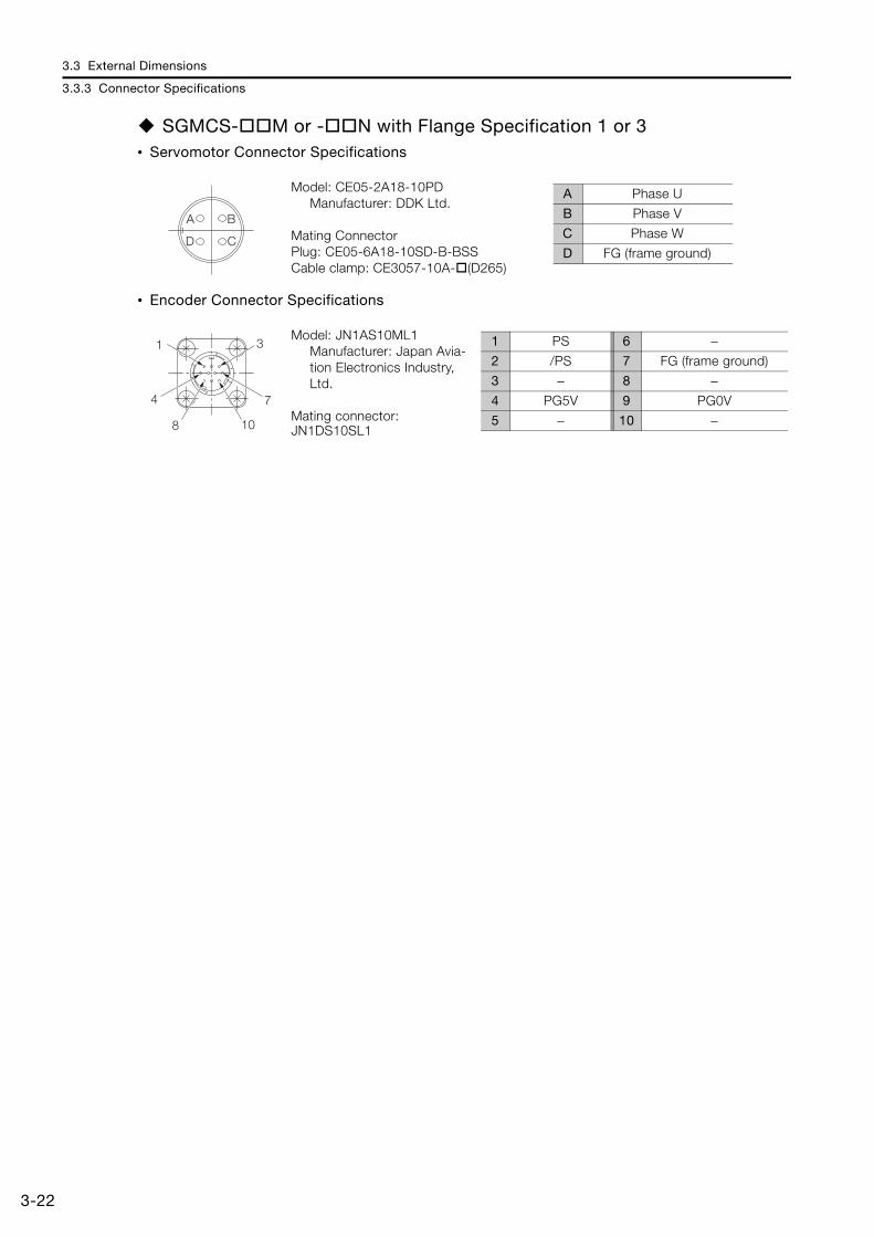
3.3 External Dimensions
3.3.3 Connector Specifications
3-22
SGMCS- M or - N with Flange Specification 1 or 3 • Servomotor Connector Specifications
• Encoder Connector Specifications
Model: CE05-2A18-10PD Manufacturer: DDK Ltd.
Mating Connector Plug: CE05-6A18-10SD-B-BSS Cable clamp: CE3057-10A- (D265)
Model: JN1AS10ML1Manufacturer: Japan Avia-tion Electronics Industry, Ltd.
Mating connector: JN1DS10SL1
BA
CD
A Phase U
B Phase V
C Phase W
D FG (frame ground)
1 3
4 7
8 10
1 PS 6 −2 /PS 7 FG (frame ground)
3 − 8 −4 PG5V 9 PG0V
5 − 10 −
This chapter describes how to interpret the model numbers of SGMCV Servomotors and gives their specifications, rat-ings, and external dimensions.
4.1 Model Designations . . . . . . . . . . . . . . . . . . 4-2
4.2 Specifications and Ratings . . . . . . . . . . . . . 4-34.2.1 Specifications . . . . . . . . . . . . . . . . . . . . . . . . . . . 4-34.2.2 Ratings . . . . . . . . . . . . . . . . . . . . . . . . . . . . . . . . 4-54.2.3 Torque-Motor Speed Characteristics . . . . . . . . . 4-64.2.4 Servomotor Overload Protection Characteristics 4-64.2.5 Load Moment of Inertia . . . . . . . . . . . . . . . . . . . . 4-74.2.6 Allowable Load Moment of Inertia Scaling
Factor for SERVOPACKs without Built-in Regenerative Resistors . . . . . . . . . . . . . . . . . . . . 4-8
4.3 External Dimensions . . . . . . . . . . . . . . . . . . 4-94.3.1 Connector Specifications . . . . . . . . . . . . . . . . . 4-11
Specifications, Ratings, and External Dimensions of SGMCV Servomotors 4
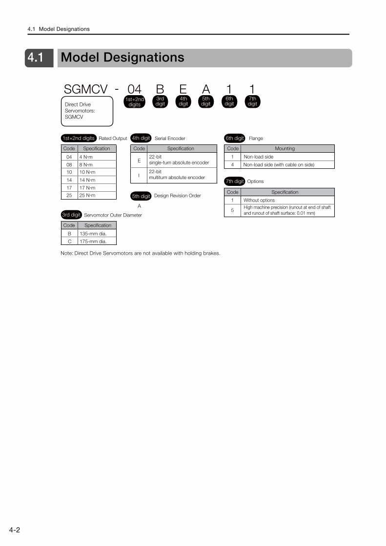
4.1 Model Designations
4-2
4.1 Model Designations
Note: Direct Drive Servomotors are not available with holding brakes.
B
C
E
I
1
5
1
4
4th digit 6th digit
3rd digit
7th digit
Mounting
Non-load side
Non-load side (with cable on side)
Options
Without optionsHigh machine precision (runout at end of shaft and runout of shaft surface: 0.01 mm)
22-bit single-turn absolute encoder
22-bit multiturn absolute encoder
A
5th digit Design Revision Order
Servomotor Outer Diameter
135-mm dia.
175-mm dia.
Serial Encoder Flange
SGMCV - 04 B E A 1 11st+2nd
digits
1st+2nd digits Rated Output
04 4 N m
08 8 N m
10 10 N m
14 14 N m
17 17 N m
25 25 N m
Code Specification
3rd digit
4th digit
5th digit
6th digit
7th digitDirect Drive
Servomotors: SGMCV
Code Code
Code
Code
Specification
Specification
Specification
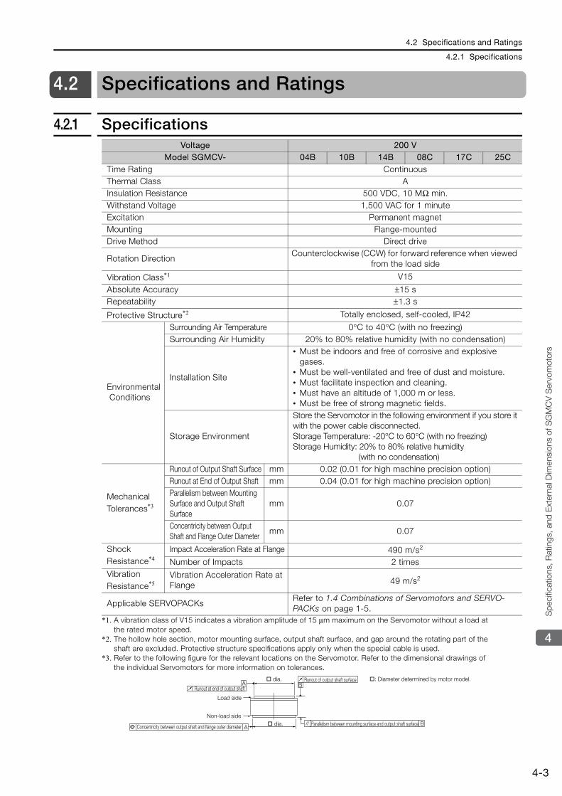
4.2 Specifications and Ratings
4.2.1 Specifications
4-3
4
Spe
cific
atio
ns, R
atin
gs, a
nd E
xter
nal D
imen
sion
s of
SG
MC
V S
ervo
mot
ors
4.2 Specifications and Ratings
4.2.1 Specifications
*1. A vibration class of V15 indicates a vibration amplitude of 15 μm maximum on the Servomotor without a load at the rated motor speed.
*2. The hollow hole section, motor mounting surface, output shaft surface, and gap around the rotating part of the shaft are excluded. Protective structure specifications apply only when the special cable is used.
*3. Refer to the following figure for the relevant locations on the Servomotor. Refer to the dimensional drawings of the individual Servomotors for more information on tolerances.
Voltage 200 VModel SGMCV- 04B 10B 14B 08C 17C 25C
Time Rating Continuous Thermal Class AInsulation Resistance 500 VDC, 10 MΩ min. Withstand Voltage 1,500 VAC for 1 minute Excitation Permanent magnet Mounting Flange-mounted Drive Method Direct drive
Rotation Direction Counterclockwise (CCW) for forward reference when viewed
from the load side
Vibration Class*1 V15
Absolute Accuracy ±15 s Repeatability ±1.3 s
Protective Structure*2 Totally enclosed, self-cooled, IP42
Environmental Conditions
Surrounding Air Temperature 0°C to 40°C (with no freezing) Surrounding Air Humidity 20% to 80% relative humidity (with no condensation)
Installation Site
• Must be indoors and free of corrosive and explosive gases.
• Must be well-ventilated and free of dust and moisture. • Must facilitate inspection and cleaning. • Must have an altitude of 1,000 m or less.• Must be free of strong magnetic fields.
Storage Environment
Store the Servomotor in the following environment if you store it with the power cable disconnected. Storage Temperature: -20°C to 60°C (with no freezing)Storage Humidity: 20% to 80% relative humidity
(with no condensation)
Mechanical Tolerances*3
Runout of Output Shaft Surface mm 0.02 (0.01 for high machine precision option) Runout at End of Output Shaft mm 0.04 (0.01 for high machine precision option) Parallelism between Mounting Surface and Output Shaft Surface
mm 0.07
Concentricity between Output Shaft and Flange Outer Diameter
mm 0.07
Shock Resistance*4
Impact Acceleration Rate at Flange 490 m/s2
Number of Impacts 2 times Vibration Resistance*5
Vibration Acceleration Rate at Flange 49 m/s2
Applicable SERVOPACKs Refer to 1.4 Combinations of Servomotors and SERVO-PACKs on page 1-5.
A
A B
B
Runout at end of output shaft
dia.
Load side
Non-load side
Concentricity between output shaft and flange outer diameter dia. Parallelism between mounting surface and output shaft surface
Runout of output shaft surface : Diameter determined by motor model.
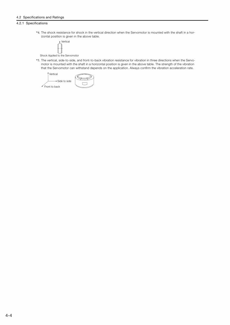
4.2 Specifications and Ratings
4.2.1 Specifications
4-4
*4. The shock resistance for shock in the vertical direction when the Servomotor is mounted with the shaft in a hor-izontal position is given in the above table.
*5. The vertical, side-to-side, and front-to-back vibration resistance for vibration in three directions when the Servo-motor is mounted with the shaft in a horizontal position is given in the above table. The strength of the vibration that the Servomotor can withstand depends on the application. Always confirm the vibration acceleration rate.
Vertical
Shock Applied to the Servomotor
Vertical
Side to side
Front to back
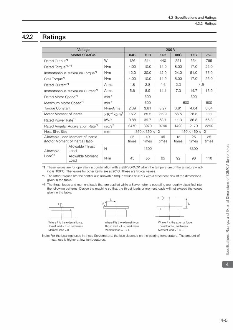
4.2 Specifications and Ratings
4.2.2 Ratings
4-5
4
Spe
cific
atio
ns, R
atin
gs, a
nd E
xter
nal D
imen
sion
s of
SG
MC
V S
ervo
mot
ors
4.2.2 Ratings
*1. These values are for operation in combination with a SERVOPACK when the temperature of the armature wind-ing is 100°C. The values for other items are at 20°C. These are typical values.
*2. The rated torques are the continuous allowable torque values at 40°C with a steel heat sink of the dimensions given in the table.
*3. The thrust loads and moment loads that are applied while a Servomotor is operating are roughly classified into the following patterns. Design the machine so that the thrust loads or moment loads will not exceed the values given in the table.
Note: For the bearings used in these Servomotors, the loss depends on the bearing temperature. The amount of heat loss is higher at low temperatures.
Voltage 200 V
Model SGMCV- 04B 10B 14B 08C 17C 25C
Rated Output*1 W 126 314 440 251 534 785
Rated Torque*1, *2 N m 4.00 10.0 14.0 8.00 17.0 25.0
Instantaneous Maximum Torque*1 N m 12.0 30.0 42.0 24.0 51.0 75.0
Stall Torque*1 N m 4.00 10.0 14.0 8.00 17.0 25.0
Rated Current*1 Arms 1.8 2.8 4.6 2.3 4.5
Instantaneous Maximum Current*1 Arms 5.6 8.9 14.1 7.3 14.7 13.9
Rated Motor Speed*1 min-1 300 300
Maximum Motor Speed*1 min-1 600 600 500
Torque Constant N m/Arms 2.39 3.81 3.27 3.81 4.04 6.04
Motor Moment of Inertia ×10-4 kg m2 16.2 25.2 36.9 56.5 78.5 111
Rated Power Rate*1 kW/s 9.88 39.7 53.1 11.3 36.8 56.3
Rated Angular Acceleration Rate*1 rad/s2 2470 3970 3790 1420 2170 2250
Heat Sink Size mm 350 × 350 × 12 450 × 450 × 12
Allowable Load Moment of Inertia (Motor Moment of Inertia Ratio)
25 times
40 times
45 times
15 times
25 times
25 times
Allowable Load*3
Allowable Thrust Load
N 1500 3300
Allowable Moment Load
N m 45 55 65 92 98 110
F
F
LF
L
Where F is the external force,Thrust load = F + Load mass Moment load = 0
Where F is the external force,Thrust load = F + Load massMoment load = F × L
Where F is the external force,Thrust load = Load massMoment load = F × L
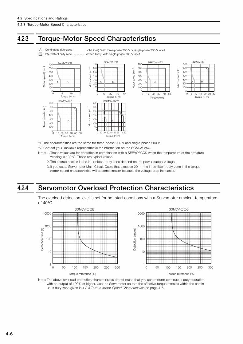
4.2 Specifications and Ratings
4.2.3 Torque-Motor Speed Characteristics
4-6
4.2.3 Torque-Motor Speed Characteristics
*1. The characteristics are the same for three-phase 200 V and single-phase 200 V.
*2. Contact your Yaskawa representative for information on the SGMCV-25C.
Note: 1. These values are for operation in combination with a SERVOPACK when the temperature of the armature winding is 100°C. These are typical values.
2. The characteristics in the intermittent duty zone depend on the power supply voltage.
3. If you use a Servomotor Main Circuit Cable that exceeds 20 m, the intermittent duty zone in the torque-motor speed characteristics will become smaller because the voltage drop increases.
4.2.4 Servomotor Overload Protection Characteristics The overload detection level is set for hot start conditions with a Servomotor ambient temperature of 40°C.
Note: The above overload protection characteristics do not mean that you can perform continuous duty operation with an output of 100% or higher. Use the Servomotor so that the effective torque remains within the contin-uous duty zone given in 4.2.3 Torque-Motor Speed Characteristics on page 4-6.
A :
B :
SGMCV-17C
0 10 20 30 40 50 600
100
200
300
400
500
600
700
A B
SGMCV-04B*1
0
100
200
300
400
500
600
700
0 5 10 15
A B
SGMCV-25C*2
SGMCV-10B
0 10 20 30 400
100
200
300
400
500
600
700
A B
SGMCV-14B*1
0 10 20 30 40 500
100
200
300
400
500
600
700
A B
SGMCV-08C
0 5 10 15 20 25 300
100
200
300
400
500
600
700
A B
Torque (N·m)
(solid lines): With three-phase 200-V or single-phase 230-V input(dotted lines): With single-phase 200-V inputIntermittent duty zone
Mot
or s
peed
(min
-1)
Continuous duty zone
Torque (N·m)
Mot
or s
peed
(min
-1)
Torque (N·m)
Mot
or s
peed
(min
-1)
Torque (N·m)
Mot
or s
peed
(min
-1)
Torque (N·m)
Mot
or s
peed
(min
-1)
Torque (N·m)
Mot
or s
peed
(min
-1)
0 10 20 30 40 50 60 70 800
100
200
300
400
500
600
700
A B
SGMCV- B SGMCV- C
Det
ectio
n tim
e (s
)
Torque reference (%) Torque reference (%)
Det
ectio
n tim
e (s
)
10000
1000
100
10
1
10000
1000
100
10
10 50 100 150 200 250 300 0 50 100 150 200 250 300
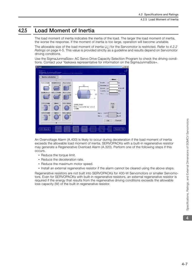
4.2 Specifications and Ratings
4.2.5 Load Moment of Inertia
4-7
4
Spe
cific
atio
ns, R
atin
gs, a
nd E
xter
nal D
imen
sion
s of
SG
MC
V S
ervo
mot
ors
4.2.5 Load Moment of InertiaThe load moment of inertia indicates the inertia of the load. The larger the load moment of inertia, the worse the response. If the moment of inertia is too large, operation will become unstable.
The allowable size of the load moment of inertia (JL) for the Servomotor is restricted. Refer to 4.2.2 Ratings on page 4-5. This value is provided strictly as a guideline and results depend on Servomotor driving conditions.
Use the SigmaJunmaSize+ AC Servo Drive Capacity Selection Program to check the driving condi-tions. Contact your Yaskawa representative for information on the SigmaJunmaSize+.
An Overvoltage Alarm (A.400) is likely to occur during deceleration if the load moment of inertia exceeds the allowable load moment of inertia. SERVOPACKs with a built-in regenerative resistor may generate a Regenerative Overload Alarm (A.320). Perform one of the following steps if this occurs.
• Reduce the torque limit. • Reduce the deceleration rate. • Reduce the maximum motor speed. • Install an external regenerative resistor if the alarm cannot be cleared using the above steps.
Regenerative resistors are not built into SERVOPACKs for 400-W Servomotors or smaller Servomo-tors. Even for SERVOPACKs with built-in regenerative resistors, an external regenerative resistor is required if the energy that results from the regenerative driving conditions exceeds the allowable loss capacity (W) of the built-in regenerative resistor.
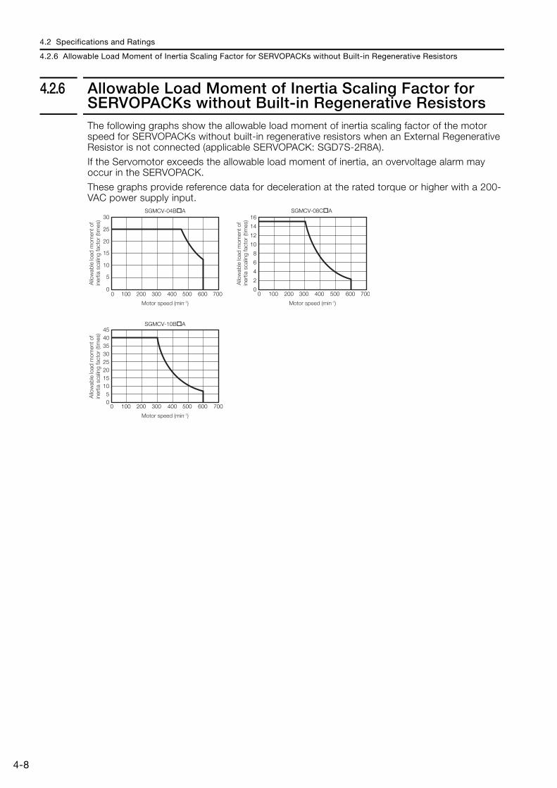
4.2 Specifications and Ratings
4.2.6 Allowable Load Moment of Inertia Scaling Factor for SERVOPACKs without Built-in Regenerative Resistors
4-8
4.2.6 Allowable Load Moment of Inertia Scaling Factor for SERVOPACKs without Built-in Regenerative ResistorsThe following graphs show the allowable load moment of inertia scaling factor of the motor speed for SERVOPACKs without built-in regenerative resistors when an External Regenerative Resistor is not connected (applicable SERVOPACK: SGD7S-2R8A).
If the Servomotor exceeds the allowable load moment of inertia, an overvoltage alarm may occur in the SERVOPACK.
These graphs provide reference data for deceleration at the rated torque or higher with a 200-VAC power supply input.
Motor speed (min-1)
Motor speed (min-1)Motor speed (min-1)
0
5
10
15
20
25
30
0 100 200 300 400 500 600 700
SGMCV-04B A
0
2
4
6
8
10
12
14
16
0 100 200 300 400 500 600 700
SGMCV-08C A
05
1015202530354045
0 100 200 300 400 500 600 700
SGMCV-10B A
Allo
wab
le lo
ad m
omen
t of
iner
tia s
calin
g fa
ctor
(tim
es)
Allo
wab
le lo
ad m
omen
t of
iner
tia s
calin
g fa
ctor
(tim
es)
Allo
wab
le lo
ad m
omen
t of
iner
tia s
calin
g fa
ctor
(tim
es)
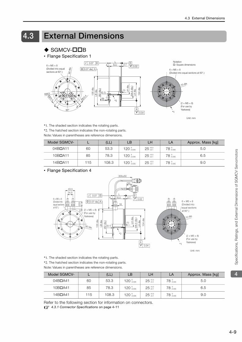
4.3 External Dimensions
4-9
4
Spe
cific
atio
ns, R
atin
gs, a
nd E
xter
nal D
imen
sion
s of
SG
MC
V S
ervo
mot
ors
4.3 External Dimensions
SGMCV- B• Flange Specification 1
*1. The shaded section indicates the rotating parts.
*2. The hatched section indicates the non-rotating parts.
Note: Values in parentheses are reference dimensions.
• Flange Specification 4
*1. The shaded section indicates the rotating parts.
*2. The hatched section indicates the non-rotating parts.
Note: Values in parentheses are reference dimensions.
Refer to the following section for information on connectors. 4.3.1 Connector Specifications on page 4-11
Model SGMCV- L (LL) LB LH LA Approx. Mass [kg]
04B A11 60 53.3 120 25 78 5.0
10B A11 85 78.3 120 25 78 6.5
14B A11 115 108.3 120 25 78 9.0
Model SGMCV- L (LL) LB LH LA Approx. Mass [kg]
04B A41 60 53.3 120 25 78 5.0
10B A41 85 78.3 120 25 78 6.5
14B A41 115 108.3 120 25 78 9.0
23
.4 25.4
(1)
2.74
90°
R26.5
(LL)L
(9)
(0.1)
A0.04
B0.02
A
0.07 B
*1
*2
6 × M5 × 8 (Divided into equal sections at 60°.)
(82
dia
.)
134
dia
.
(58.
5 d
ia.)
LB d
ia.
135
dia
.
0.07 dia. 6 × M5 × 8 (Divided into equal sections at 60°.)
(2 × M5 × 8) (For use by Yaskawa)
70 dia.
Unit: mm
90 d
ia.
LA d
ia.
LH d
ia.
Notation : Square dimensions
0-0.035
+0.3+0.1
0-0.030
0-0.035
+0.3+0.1
0-0.030
0-0.035
+0.3+0.1
0-0.030
(1)
2.7(LL)L
300±50
(35)
18
4
(0.1)
43.524.5
10(2
2)
A0.04
B
0.020.07 B
A
90 dia.
*1
*2
6 × M5 × 8 (Divided into equal sections at 60°.)
0.07 dia.
(2 × M5 × 8) (For use by Yaskawa)
134
dia
.
(58.
5 d
ia.)
LH d
ia.
(82
dia
.)
135
dia
.
6 × M5 × 8 (Divided into equal sections at 60°.)
(2 × M5 × 8) (For use by Yaskawa)
Unit: mm
70 dia.
LB d
ia.
LA d
ia.
0-0.035
+0.3+0.1
0-0.030
0-0.035
+0.3+0.1
0-0.030
0-0.035
+0.3+0.1
0-0.030
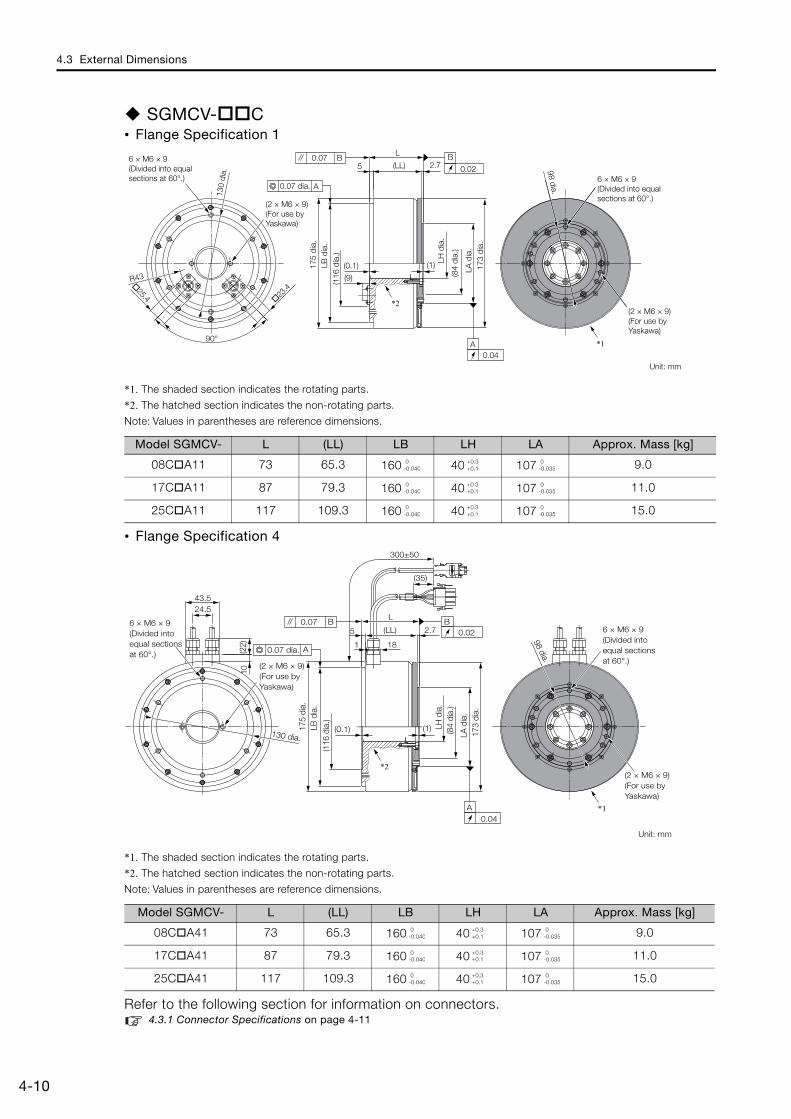
4.3 External Dimensions
4-10
SGMCV- C• Flange Specification 1
*1. The shaded section indicates the rotating parts.
*2. The hatched section indicates the non-rotating parts.
Note: Values in parentheses are reference dimensions.
• Flange Specification 4
*1. The shaded section indicates the rotating parts.
*2. The hatched section indicates the non-rotating parts.
Note: Values in parentheses are reference dimensions.
Refer to the following section for information on connectors.4.3.1 Connector Specifications on page 4-11
Model SGMCV- L (LL) LB LH LA Approx. Mass [kg]
08C A11 73 65.3 160 40 107 9.0
17C A11 87 79.3 160 40 107 11.0
25C A11 117 109.3 160 40 107 15.0
Model SGMCV- L (LL) LB LH LA Approx. Mass [kg]
08C A41 73 65.3 160 40 107 9.0
17C A41 87 79.3 160 40 107 11.0
25C A41 117 109.3 160 40 107 15.0
23.425.4
2.75
R43(0.1) (1)
90°
L
(LL)
(9)
B
0.02
A0.04
0.07 B
A
173
dia.
*1
*2
130
dia.
6 × M6 × 9 (Divided into equal sections at 60°.)
98 dia.
(2 × M6 × 9) (For use by Yaskawa)
Unit: mm
(2 × M6 × 9) (For use by Yaskawa)
LA d
ia.
(84
dia.
)
(116
dia
.)
175
dia.
0.07 dia.
LB d
ia.
LH d
ia.
6 × M6 × 9 (Divided into equal sections at 60°.)
0-0.040
+0.3+0.1
0-0.035
0-0.040
+0.3+0.1
0-0.035
0-0.040
+0.3+0.1
0-0.035
B0.022.75
1
(0.1) (1)
L
18
300±50
(LL)
24.5
(22)
43.5
10
(35)
0.07 B
A
A0.04
*1
*2
6 × M6 × 9 (Divided into equal sections at 60°.)
(2 × M6 × 9) (For use by Yaskawa)
173
dia.
(84
dia.
)
175
dia.
130 dia.
6 × M6 × 9 (Divided into equal sections at 60°.)
98 dia.
(2 × M6 × 9) (For use by Yaskawa)
Unit: mm
(116
dia
.)
0.07 dia.
LB d
ia.
LH d
ia.
LA d
ia.
0-0.040
+0.3+0.1
0-0.035
0-0.040
+0.3+0.1
0-0.035
0-0.040
+0.3+0.1
0-0.035
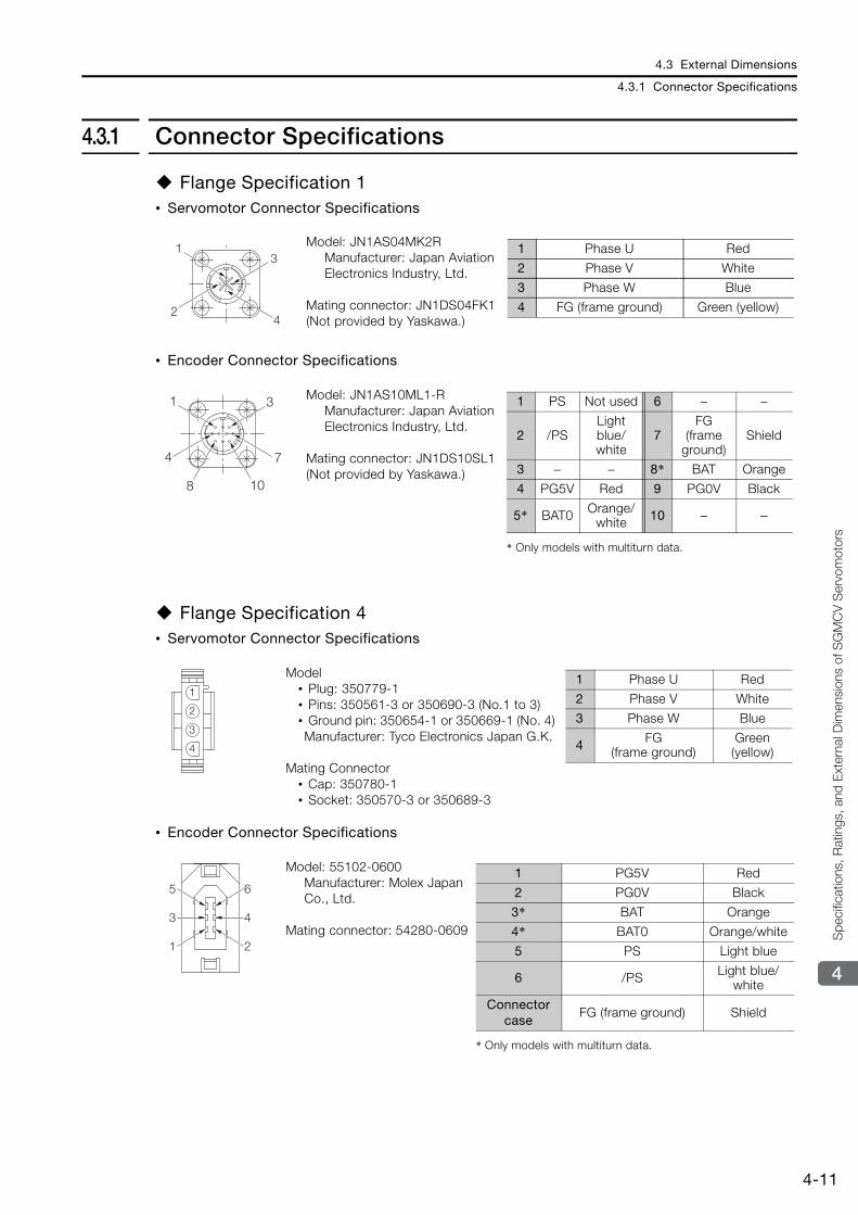
4.3 External Dimensions
4.3.1 Connector Specifications
4-11
4
Spe
cific
atio
ns, R
atin
gs, a
nd E
xter
nal D
imen
sion
s of
SG
MC
V S
ervo
mot
ors
4.3.1 Connector Specifications
Flange Specification 1 • Servomotor Connector Specifications
• Encoder Connector Specifications
Flange Specification 4 • Servomotor Connector Specifications
• Encoder Connector Specifications
Model: JN1AS04MK2R Manufacturer: Japan Aviation Electronics Industry, Ltd.
Mating connector: JN1DS04FK1 (Not provided by Yaskawa.)
Model: JN1AS10ML1-R Manufacturer: Japan Aviation Electronics Industry, Ltd.
Mating connector: JN1DS10SL1 (Not provided by Yaskawa.)
Model • Plug: 350779-1 • Pins: 350561-3 or 350690-3 (No.1 to 3) • Ground pin: 350654-1 or 350669-1 (No. 4) Manufacturer: Tyco Electronics Japan G.K.
Mating Connector • Cap: 350780-1 • Socket: 350570-3 or 350689-3
Model: 55102-0600Manufacturer: Molex Japan Co., Ltd.
Mating connector: 54280-0609
13
24
1 Phase U Red
2 Phase V White
3 Phase W Blue
4 FG (frame ground) Green (yellow)
1 3
4 7
8 10
* Only models with multiturn data.
1 PS Not used 6 − −
2 /PSLight blue/white
7FG
(frame ground)
Shield
3 − − 8* BAT Orange
4 PG5V Red 9 PG0V Black
5* BAT0 Orange/white 10 − −
1
2
3
4
1 Phase U Red
2 Phase V White
3 Phase W Blue
4 FG (frame ground)
Green (yellow)
4
2
6
3
1
5
* Only models with multiturn data.
1 PG5V Red
2 PG0V Black
3* BAT Orange
4* BAT0 Orange/white
5 PS Light blue
6 /PS Light blue/white
Connector case
FG (frame ground) Shield
This chapter describes the installation conditions and pre-cautions for Servomotors.
5.1 Installation Conditions . . . . . . . . . . . . . . . . 5-25.1.1 Installation Precautions . . . . . . . . . . . . . . . . . . . . 5-25.1.2 Installation Environment . . . . . . . . . . . . . . . . . . . 5-35.1.3 Installation Orientation . . . . . . . . . . . . . . . . . . . . 5-3
5.2 Mounting to the Machine . . . . . . . . . . . . . . 5-4
5.3 Oil and Water Countermeasures . . . . . . . . . 5-5
5.4 Equipment Structure . . . . . . . . . . . . . . . . . . 5-65.4.1 Minimum Angle of Oscillation . . . . . . . . . . . . . . . 5-65.4.2 Precautions on Passing the Origin . . . . . . . . . . . 5-6
5.5 Servomotor Temperature Increase . . . . . . . 5-7
Servomotor Installation 5
5.1 Installation Conditions
5.1.1 Installation Precautions
5-2
5.1 Installation Conditions
The service life of a Servomotor will be shortened or unexpected problems will occur if the Ser-vomotor is installed incorrectly or in an inappropriate location. Always observe the following installation instructions.
5.1.1 Installation Precautions
CAUTIONImplement safety measures, such as installing a cover so that the rotating part of the Direct Drive Servomotor cannot be touched accidentally during operation.Never use the Servomotor in an environment that is subject to water, corrosive gases, or flammable gases, or near flammable objects. Failure to observe this caution may result in electric shock or fire.
• Mount the Servomotor to a nonflammable material. Installation directly onto or near flammable objects may result in fire.
• Mount the SERVOPACK and Direct Drive Servomotor on a structure that will support the masses that are given in the user’s manuals.
• Do not step on or place a heavy object on the Servomotor. Failure to observe this caution may result in injury.
• Install the Servomotor within the specified ambient conditions. Refer to the specifications for each type of Servomotor for the ambient conditions.
• Direct Drive Servomotors are precision devices. Never drop a Servomotor or subject it to strong shock.
• Do not place a Direct Drive Servomotor with the connector side facing down. Doing so will damage the connectors.
• Do not place any load on the cover on the rotating part of an SGMCV Direct Drive Servomotor. Doing so will deform or damage the cover.
• Do not attempt to install or operate a Direct Drive Servomotor that is damaged or missing parts.
• When you transport a Direct Drive Servomotor, do not hold onto the cables, rotating part, or connectors. Failure to observe this caution may result in damage or injury.
• Securely mount the Direct Drive Servomotor onto the machine. If the Servomotor is not mounted securely, it may come off during operation, possibly causing injury.
• When you couple the load to the Direct Drive Servomotor, do not strike the Servomotor with a hammer or otherwise subject it to shock. Failure to observe this caution may result in damage to the encoder.
• Do not place more than the allowable load on the rotating part of the Direct Drive Servomotor. Failure to observe this caution may result in damage to the rotating part.
• Consult your Yaskawa representative if you plan to use a Direct Drive Servomotor that has been stored for an extended period of time.
• Check the level of vibration while the Direct Drive Servomotor is mounted to the machine. If the vibration is too strong, the bearings and encoder will be damaged faster, faulty connector con-tacts may occur, and bolts may become loose.
• When you adjust the gain during equipment commissioning, use a measuring instrument to monitor the torque waveform and speed waveform and confirm that there is no vibration. If a high gain causes vibration, the Direct Drive Servomotor will be damaged faster.
Important
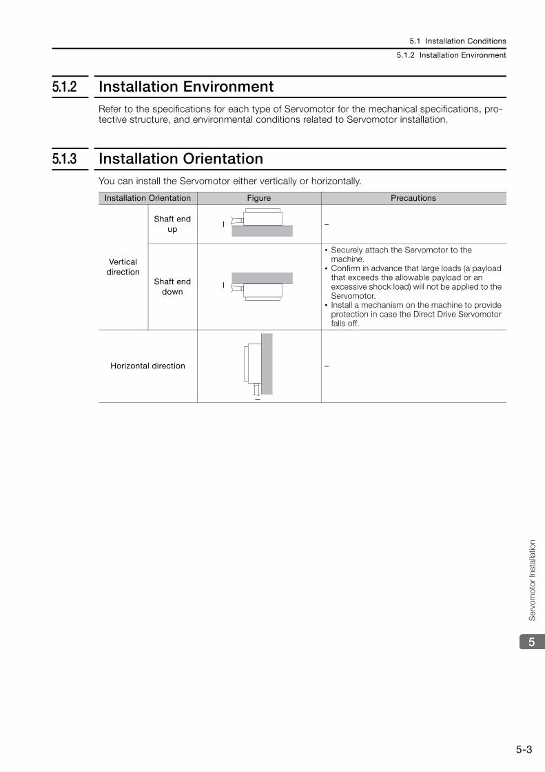
5.1 Installation Conditions
5.1.2 Installation Environment
5-3
5
Ser
vom
otor
Inst
alla
tion
5.1.2 Installation EnvironmentRefer to the specifications for each type of Servomotor for the mechanical specifications, pro-tective structure, and environmental conditions related to Servomotor installation.
5.1.3 Installation OrientationYou can install the Servomotor either vertically or horizontally.
Installation Orientation Figure Precautions
Vertical direction
Shaft end up
–
Shaft end down
• Securely attach the Servomotor to the machine.
• Confirm in advance that large loads (a payload that exceeds the allowable payload or an excessive shock load) will not be applied to the Servomotor.
• Install a mechanism on the machine to provide protection in case the Direct Drive Servomotor falls off.
Horizontal direction –
5.2 Mounting to the Machine
5-4
5.2 Mounting to the Machine
• Allowable Loads
When you connect a load to the Servomotor, do not place a load on the rotating part that exceeds the allowable limits. If you exceed the allowable limits, the service life of the bearings will be reduced and the rotating part will be damaged.Refer to the specifications for each type of Direct Drive Servomotor for the allowable loads on the rotating part of the Servomotor.
• When you mount the Direct Drive Servomotor to the machine, use the flange outer diameter to center the Servomotor and the machine.
• When you couple the Direct Drive Servomotor to the load, sufficiently center the output shaft with the load. Consult your Yaskawa representative if you plan to use a rigid coupling with the machine shaft.
The allowable loads that are given in the specifications include the static load in one direction and the dynamic load that occurs during rotation. Consider the dynamic load when you select a Ser-vomotor or design the equipment.
Important
Note
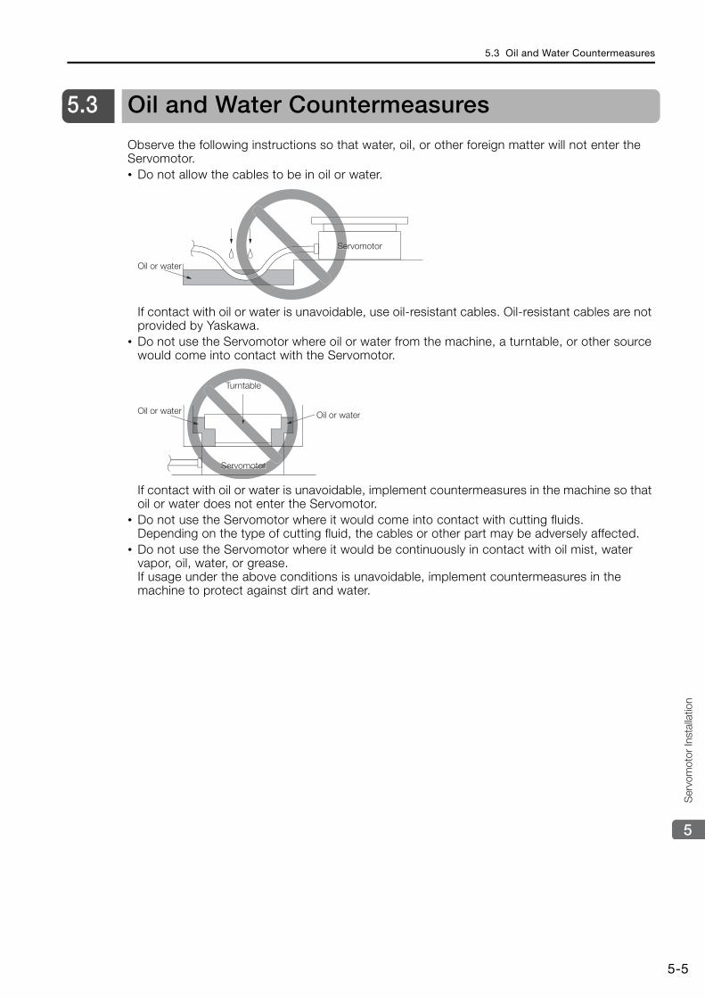
5.3 Oil and Water Countermeasures
5-5
5
Ser
vom
otor
Inst
alla
tion
5.3 Oil and Water Countermeasures
Observe the following instructions so that water, oil, or other foreign matter will not enter the Servomotor.• Do not allow the cables to be in oil or water.
If contact with oil or water is unavoidable, use oil-resistant cables. Oil-resistant cables are not provided by Yaskawa.
• Do not use the Servomotor where oil or water from the machine, a turntable, or other source would come into contact with the Servomotor.
If contact with oil or water is unavoidable, implement countermeasures in the machine so that oil or water does not enter the Servomotor.
• Do not use the Servomotor where it would come into contact with cutting fluids.Depending on the type of cutting fluid, the cables or other part may be adversely affected.
• Do not use the Servomotor where it would be continuously in contact with oil mist, water vapor, oil, water, or grease.If usage under the above conditions is unavoidable, implement countermeasures in the machine to protect against dirt and water.
Oil or water
ServomotorSe
Servomotor
Turntable
Oil or waterOil or water
Servomotor
5.4 Equipment Structure
5.4.1 Minimum Angle of Oscillation
5-6
5.4 Equipment Structure
5.4.1 Minimum Angle of OscillationIf you use a Direct Drive Servomotor for oscillating rotation, rotate the Servomotor 90° or more at least once a day to ensure sufficient bearing lubrication.Consult your Yaskawa representative if you cannot perform this operation.
5.4.2 Precautions on Passing the Origin• If you use an SGMCS Servomotor with an Incremental Encoder, you must perform an origin
return operation after you turn ON the power supply.If you use the SERVOPACK’s origin pulse (phase C) output, rotate the Direct Drive Servomo-tor at least two turns before you start the origin return operation.If the Direct Drive Servomotor cannot be rotated two or more times, perform an origin return operation at a motor speed of 6 min-1 or lower.
• If the equipment structure prevents the Direct Drive Servomotor from rotating a complete turn, install the Servomotor so that the origin within one encoder rotation is passed.
5.5 Servomotor Temperature Increase
5-7
5
Ser
vom
otor
Inst
alla
tion
5.5 Servomotor Temperature Increase
This section describes measures to suppress temperature increases in the Servomotor.• When you install the Servomotor, observe the cooling conditions (heat sink sizes) that are
given in the specifications for each type of Servomotor.The Servomotor generates heat when it operates. The heat generated by the Servomotor radiates to the heat sink through the motor mounting surface. Therefore, if the surface area of the heat sink is too small, the temperature of the Servomotor may increase abnormally.
• If the operating environment makes it difficult to use a large heat sink, or if the ambient oper-ating temperature or altitude given in the specifications is exceeded, implement the following measures.
• Derate the Servomotor.Contact your Yaskawa representative for information on derating.
• Use external forced-air cooling for the Servomotor with a cooling fan or other means.
Do not place packing or any other insulating material between the Servomotor and heat sink. Doing so will cause the motor temperature to increase, affect resistance to noise, and may cause motor failure.Important
This chapter describes the cables that are used to connect the Servomotors and SERVOPACKs and provides related precautions.
6.1 Selecting Cables . . . . . . . . . . . . . . . . . . . . . 6-26.1.1 System Configurations . . . . . . . . . . . . . . . . . . . . 6-26.1.2 Servomotor Main Circuit Cables . . . . . . . . . . . . . 6-26.1.3 Encoder Cables of 20 m or Less . . . . . . . . . . . . . 6-46.1.4 Relay Encoder Cables of 30 m to 50 m . . . . . . . . 6-6
6.2 Wiring Servomotors and SERVOPACKs . . . 6-86.2.1 Wiring Precautions . . . . . . . . . . . . . . . . . . . . . . . 6-86.2.2 Wiring Procedure . . . . . . . . . . . . . . . . . . . . . . . 6-10
Connections between Servomotors and SERVOPACKs 6
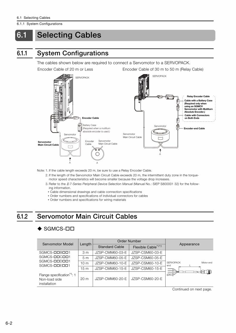
6.1 Selecting Cables
6.1.1 System Configurations
6-2
6.1 Selecting Cables
6.1.1 System ConfigurationsThe cables shown below are required to connect a Servomotor to a SERVOPACK.
Note: 1. If the cable length exceeds 20 m, be sure to use a Relay Encoder Cable.
2. If the length of the Servomotor Main Circuit Cable exceeds 20 m, the intermittent duty zone in the torque-motor speed characteristics will become smaller because the voltage drop increases.
3. Refer to the Σ-7-Series Peripheral Device Selection Manual (Manual No.: SIEP S800001 32) for the follow-ing information.
• Cable dimensional drawings and cable connection specifications• Order numbers and specifications of individual connectors for cables• Order numbers and specifications for wiring materials
6.1.2 Servomotor Main Circuit Cables
SGMCS-
Encoder Cable of 20 m or Less Encoder Cable of 30 m to 50 m (Relay Cable)
SERVOPACK
Encoder Cable
Encoder Cable
Servomotor
Servomotor Main Circuit Cable
Servomotor Main Circuit Cable
A A
Battery Case (Required when a multiturn absolute encoder is used.)
Encoder-end CableServomotor
A
SERVOPACK
Relay Encoder Cable
Cable with a Battery Case(Required only when using an SGMCV Servomotor with Multiturn Absolute Encoder.)Cable with Connectors on Both Ends
Servomotor Main Circuit Cable
Servomotor Model LengthOrder Number
AppearanceStandard Cable Flexible Cable*1*2
SGMCS- B 1SGMCS- C 1SGMCS- D 1SGMCS- E 1
Flange specification*3: 1Non-load side installation
3 m JZSP-CMM60-03-E JZSP-CSM60-03-E
5 m JZSP-CMM60-05-E JZSP-CSM60-05-E
10 m JZSP-CMM60-10-E JZSP-CSM60-10-E
15 m JZSP-CMM60-15-E JZSP-CSM60-15-E
20 m JZSP-CMM60-20-E JZSP-CSM60-20-E
Continued on next page.
LSERVOPACK end
Motor end
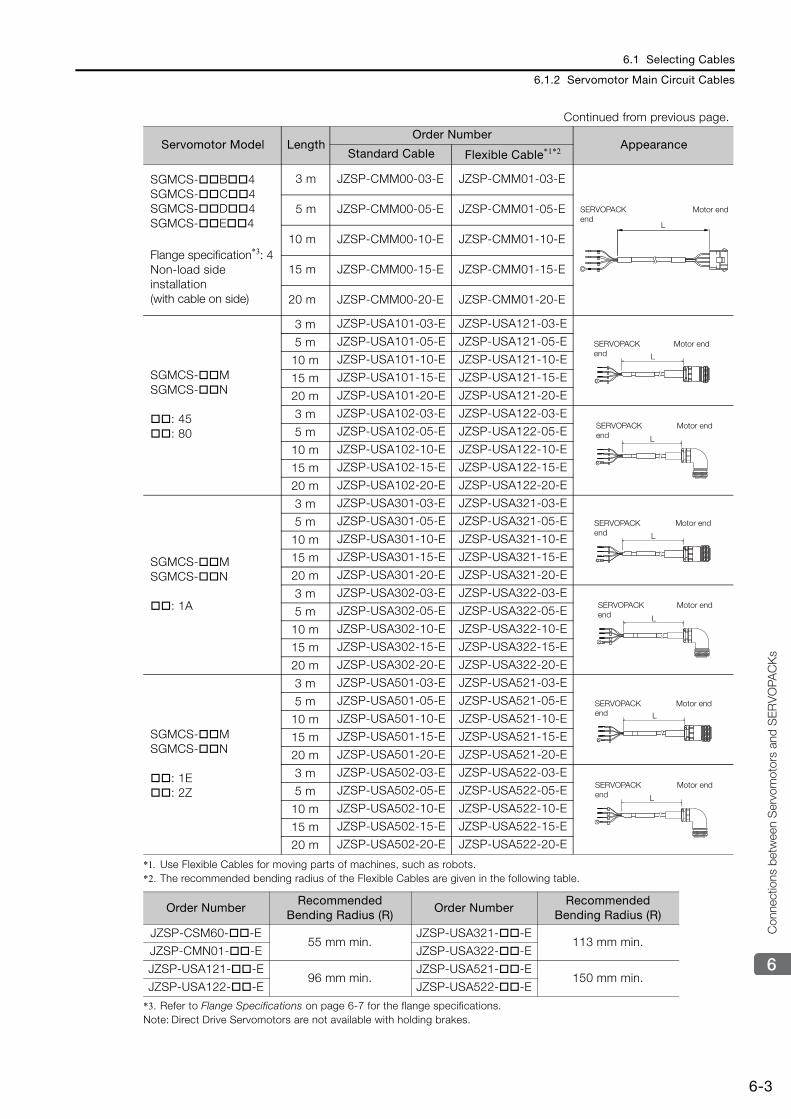
6.1 Selecting Cables
6.1.2 Servomotor Main Circuit Cables
6-3
6
Con
nect
ions
bet
wee
n S
ervo
mot
ors
and
SE
RV
OPA
CK
s
*1. Use Flexible Cables for moving parts of machines, such as robots.*2. The recommended bending radius of the Flexible Cables are given in the following table.
*3. Refer to Flange Specifications on page 6-7 for the flange specifications.Note: Direct Drive Servomotors are not available with holding brakes.
SGMCS- B 4SGMCS- C 4SGMCS- D 4SGMCS- E 4
Flange specification*3: 4Non-load side installation(with cable on side)
3 m JZSP-CMM00-03-E JZSP-CMM01-03-E
5 m JZSP-CMM00-05-E JZSP-CMM01-05-E
10 m JZSP-CMM00-10-E JZSP-CMM01-10-E
15 m JZSP-CMM00-15-E JZSP-CMM01-15-E
20 m JZSP-CMM00-20-E JZSP-CMM01-20-E
SGMCS- MSGMCS- N
: 45: 80
3 m JZSP-USA101-03-E JZSP-USA121-03-E
5 m JZSP-USA101-05-E JZSP-USA121-05-E
10 m JZSP-USA101-10-E JZSP-USA121-10-E
15 m JZSP-USA101-15-E JZSP-USA121-15-E
20 m JZSP-USA101-20-E JZSP-USA121-20-E
3 m JZSP-USA102-03-E JZSP-USA122-03-E
5 m JZSP-USA102-05-E JZSP-USA122-05-E
10 m JZSP-USA102-10-E JZSP-USA122-10-E
15 m JZSP-USA102-15-E JZSP-USA122-15-E
20 m JZSP-USA102-20-E JZSP-USA122-20-E
SGMCS- MSGMCS- N
: 1A
3 m JZSP-USA301-03-E JZSP-USA321-03-E
5 m JZSP-USA301-05-E JZSP-USA321-05-E
10 m JZSP-USA301-10-E JZSP-USA321-10-E
15 m JZSP-USA301-15-E JZSP-USA321-15-E
20 m JZSP-USA301-20-E JZSP-USA321-20-E
3 m JZSP-USA302-03-E JZSP-USA322-03-E
5 m JZSP-USA302-05-E JZSP-USA322-05-E
10 m JZSP-USA302-10-E JZSP-USA322-10-E
15 m JZSP-USA302-15-E JZSP-USA322-15-E
20 m JZSP-USA302-20-E JZSP-USA322-20-E
SGMCS- MSGMCS- N
: 1E: 2Z
3 m JZSP-USA501-03-E JZSP-USA521-03-E
5 m JZSP-USA501-05-E JZSP-USA521-05-E
10 m JZSP-USA501-10-E JZSP-USA521-10-E
15 m JZSP-USA501-15-E JZSP-USA521-15-E
20 m JZSP-USA501-20-E JZSP-USA521-20-E
3 m JZSP-USA502-03-E JZSP-USA522-03-E
5 m JZSP-USA502-05-E JZSP-USA522-05-E
10 m JZSP-USA502-10-E JZSP-USA522-10-E
15 m JZSP-USA502-15-E JZSP-USA522-15-E
20 m JZSP-USA502-20-E JZSP-USA522-20-E
Order NumberRecommended
Bending Radius (R)Order Number
Recommended Bending Radius (R)
JZSP-CSM60- -E55 mm min.
JZSP-USA321- -E113 mm min.
JZSP-CMN01- -E JZSP-USA322- -E
JZSP-USA121- -E96 mm min.
JZSP-USA521- -E150 mm min.
JZSP-USA122- -E JZSP-USA522- -E
Continued from previous page.
Servomotor Model LengthOrder Number
AppearanceStandard Cable Flexible Cable*1*2
L
SERVOPACK end
Motor end
L
SERVOPACK end
Motor end
L
SERVOPACK end
Motor end
L
SERVOPACK end
Motor end
L
SERVOPACK end
Motor end
L
SERVOPACK end
Motor end
L
SERVOPACK end
Motor end
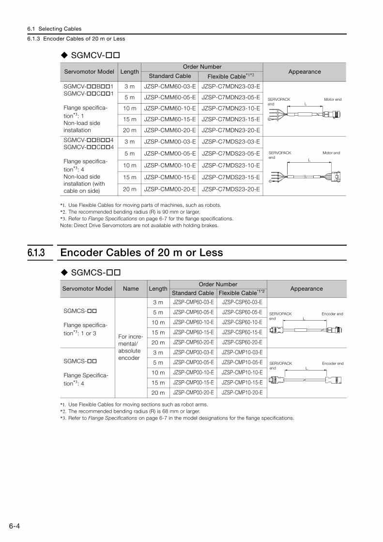
6.1 Selecting Cables
6.1.3 Encoder Cables of 20 m or Less
6-4
SGMCV-
*1. Use Flexible Cables for moving parts of machines, such as robots.*2. The recommended bending radius (R) is 90 mm or larger.*3. Refer to Flange Specifications on page 6-7 for the flange specifications.Note: Direct Drive Servomotors are not available with holding brakes.
6.1.3 Encoder Cables of 20 m or Less
SGMCS-
*1. Use Flexible Cables for moving sections such as robot arms.*2. The recommended bending radius (R) is 68 mm or larger.*3. Refer to Flange Specifications on page 6-7 in the model designations for the flange specifications.
Servomotor Model LengthOrder Number
AppearanceStandard Cable Flexible Cable*1*2
SGMCV- B 1SGMCV- C 1
Flange specifica-tion*3: 1Non-load side installation
3 m JZSP-CMM60-03-E JZSP-C7MDN23-03-E
5 m JZSP-CMM60-05-E JZSP-C7MDN23-05-E
10 m JZSP-CMM60-10-E JZSP-C7MDN23-10-E
15 m JZSP-CMM60-15-E JZSP-C7MDN23-15-E
20 m JZSP-CMM60-20-E JZSP-C7MDN23-20-E
SGMCV- B 4SGMCV- C 4
Flange specifica-tion*3: 4Non-load side installation (with cable on side)
3 m JZSP-CMM00-03-E JZSP-C7MDS23-03-E
5 m JZSP-CMM00-05-E JZSP-C7MDS23-05-E
10 m JZSP-CMM00-10-E JZSP-C7MDS23-10-E
15 m JZSP-CMM00-15-E JZSP-C7MDS23-15-E
20 m JZSP-CMM00-20-E JZSP-C7MDS23-20-E
LSERVOPACK end
Motor end
L
SERVOPACK end
Motor end
Servomotor Model Name LengthOrder Number
AppearanceStandard Cable Flexible Cable*1*2
SGMCS-
Flange specifica-tion*3: 1 or 3 For incre-
mental/absolute encoder
3 m JZSP-CMP60-03-E JZSP-CSP60-03-E
5 m JZSP-CMP60-05-E JZSP-CSP60-05-E
10 m JZSP-CMP60-10-E JZSP-CSP60-10-E
15 m JZSP-CMP60-15-E JZSP-CSP60-15-E
20 m JZSP-CMP60-20-E JZSP-CSP60-20-E
SGMCS-
Flange Specifica-tion*3: 4
3 m JZSP-CMP00-03-E JZSP-CMP10-03-E
5 m JZSP-CMP00-05-E JZSP-CMP10-05-E
10 m JZSP-CMP00-10-E JZSP-CMP10-10-E
15 m JZSP-CMP00-15-E JZSP-CMP10-15-E
20 m JZSP-CMP00-20-E JZSP-CMP10-20-E
LSERVOPACK end
Encoder end
LSERVOPACK end
Encoder end
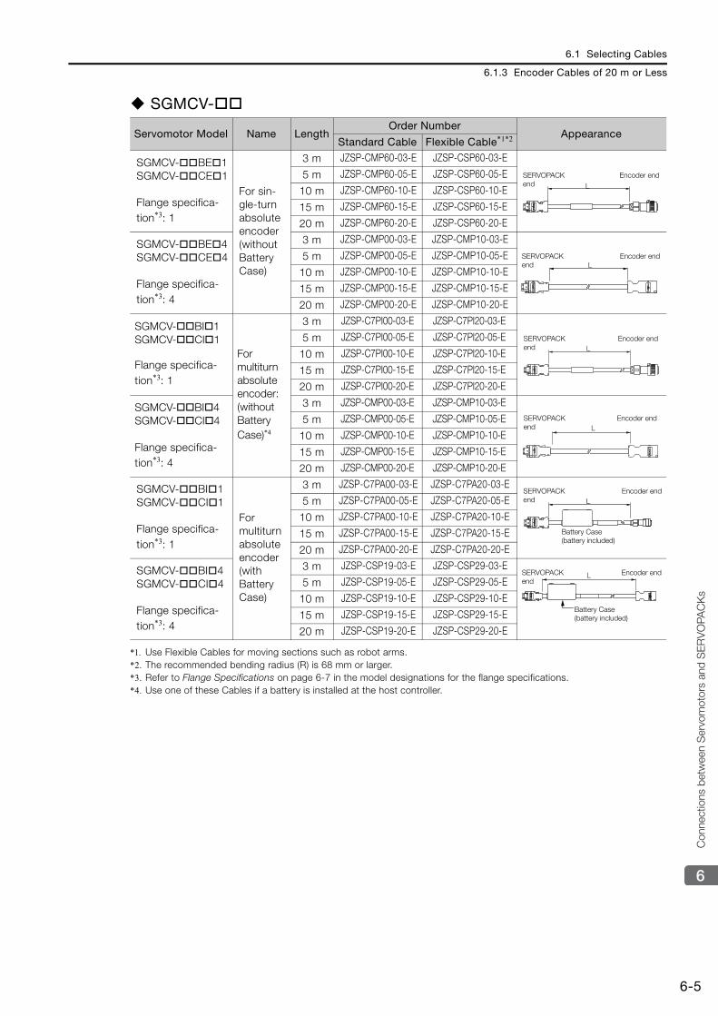
6.1 Selecting Cables
6.1.3 Encoder Cables of 20 m or Less
6-5
6
Con
nect
ions
bet
wee
n S
ervo
mot
ors
and
SE
RV
OPA
CK
s
SGMCV-
*1. Use Flexible Cables for moving sections such as robot arms.*2. The recommended bending radius (R) is 68 mm or larger.*3. Refer to Flange Specifications on page 6-7 in the model designations for the flange specifications.*4. Use one of these Cables if a battery is installed at the host controller.
Servomotor Model Name LengthOrder Number
AppearanceStandard Cable Flexible Cable*1*2
SGMCV- BE 1SGMCV- CE 1
Flange specifica-tion*3: 1
For sin-gle-turn absolute encoder(without Battery Case)
3 m JZSP-CMP60-03-E JZSP-CSP60-03-E
5 m JZSP-CMP60-05-E JZSP-CSP60-05-E
10 m JZSP-CMP60-10-E JZSP-CSP60-10-E
15 m JZSP-CMP60-15-E JZSP-CSP60-15-E
20 m JZSP-CMP60-20-E JZSP-CSP60-20-E
SGMCV- BE 4SGMCV- CE 4
Flange specifica-tion*3: 4
3 m JZSP-CMP00-03-E JZSP-CMP10-03-E
5 m JZSP-CMP00-05-E JZSP-CMP10-05-E
10 m JZSP-CMP00-10-E JZSP-CMP10-10-E
15 m JZSP-CMP00-15-E JZSP-CMP10-15-E
20 m JZSP-CMP00-20-E JZSP-CMP10-20-E
SGMCV- BI 1SGMCV- CI 1
Flange specifica-tion*3: 1
For multiturn absolute encoder:(without Battery Case)*4
3 m JZSP-C7PI00-03-E JZSP-C7PI20-03-E
5 m JZSP-C7PI00-05-E JZSP-C7PI20-05-E
10 m JZSP-C7PI00-10-E JZSP-C7PI20-10-E
15 m JZSP-C7PI00-15-E JZSP-C7PI20-15-E
20 m JZSP-C7PI00-20-E JZSP-C7PI20-20-E
SGMCV- BI 4SGMCV- CI 4
Flange specifica-tion*3: 4
3 m JZSP-CMP00-03-E JZSP-CMP10-03-E
5 m JZSP-CMP00-05-E JZSP-CMP10-05-E
10 m JZSP-CMP00-10-E JZSP-CMP10-10-E
15 m JZSP-CMP00-15-E JZSP-CMP10-15-E
20 m JZSP-CMP00-20-E JZSP-CMP10-20-E
SGMCV- BI 1SGMCV- CI 1
Flange specifica-tion*3: 1
For multiturn absolute encoder(with Battery Case)
3 m JZSP-C7PA00-03-E JZSP-C7PA20-03-E
5 m JZSP-C7PA00-05-E JZSP-C7PA20-05-E
10 m JZSP-C7PA00-10-E JZSP-C7PA20-10-E
15 m JZSP-C7PA00-15-E JZSP-C7PA20-15-E
20 m JZSP-C7PA00-20-E JZSP-C7PA20-20-E
SGMCV- BI 4SGMCV- CI 4
Flange specifica-tion*3: 4
3 m JZSP-CSP19-03-E JZSP-CSP29-03-E
5 m JZSP-CSP19-05-E JZSP-CSP29-05-E
10 m JZSP-CSP19-10-E JZSP-CSP29-10-E
15 m JZSP-CSP19-15-E JZSP-CSP29-15-E
20 m JZSP-CSP19-20-E JZSP-CSP29-20-E
L
SERVOPACK end
Encoder end
LSERVOPACK end
Encoder end
LSERVOPACK end
Encoder end
LSERVOPACK end
Encoder end
LSERVOPACK end
Encoder end
Battery Case (battery included)
SERVOPACK end
Encoder end
Battery Case (battery included)
L
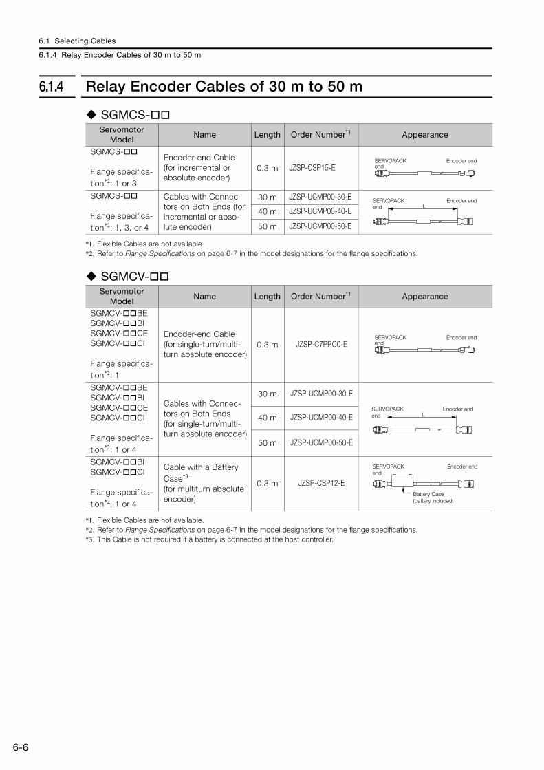
6.1 Selecting Cables
6.1.4 Relay Encoder Cables of 30 m to 50 m
6-6
6.1.4 Relay Encoder Cables of 30 m to 50 m
SGMCS-
*1. Flexible Cables are not available.*2. Refer to Flange Specifications on page 6-7 in the model designations for the flange specifications.
SGMCV-
*1. Flexible Cables are not available.*2. Refer to Flange Specifications on page 6-7 in the model designations for the flange specifications.*3. This Cable is not required if a battery is connected at the host controller.
Servomotor Model
Name Length Order Number*1 Appearance
SGMCS-
Flange specifica-tion*2: 1 or 3
Encoder-end Cable (for incremental or absolute encoder)
0.3 m JZSP-CSP15-E
SGMCS-
Flange specifica-tion*2: 1, 3, or 4
Cables with Connec-tors on Both Ends (for incremental or abso-lute encoder)
30 m JZSP-UCMP00-30-E
40 m JZSP-UCMP00-40-E
50 m JZSP-UCMP00-50-E
Servomotor Model
Name Length Order Number*1 Appearance
SGMCV- BESGMCV- BISGMCV- CESGMCV- CI
Flange specifica-tion*2: 1
Encoder-end Cable (for single-turn/multi-turn absolute encoder)
0.3 m JZSP-C7PRC0-E
SGMCV- BESGMCV- BISGMCV- CESGMCV- CI
Flange specifica-tion*2: 1 or 4
Cables with Connec-tors on Both Ends(for single-turn/multi-turn absolute encoder)
30 m JZSP-UCMP00-30-E
40 m JZSP-UCMP00-40-E
50 m JZSP-UCMP00-50-E
SGMCV- BISGMCV- CI
Flange specifica-tion*2: 1 or 4
Cable with a Battery Case*3
(for multiturn absolute encoder)
0.3 m JZSP-CSP12-E
SERVOPACK end
Encoder end
LSERVOPACK end
Encoder end
SERVOPACK end
Encoder end
LSERVOPACK end
Encoder end
SERVOPACK end
Encoder end
Battery Case (battery included)
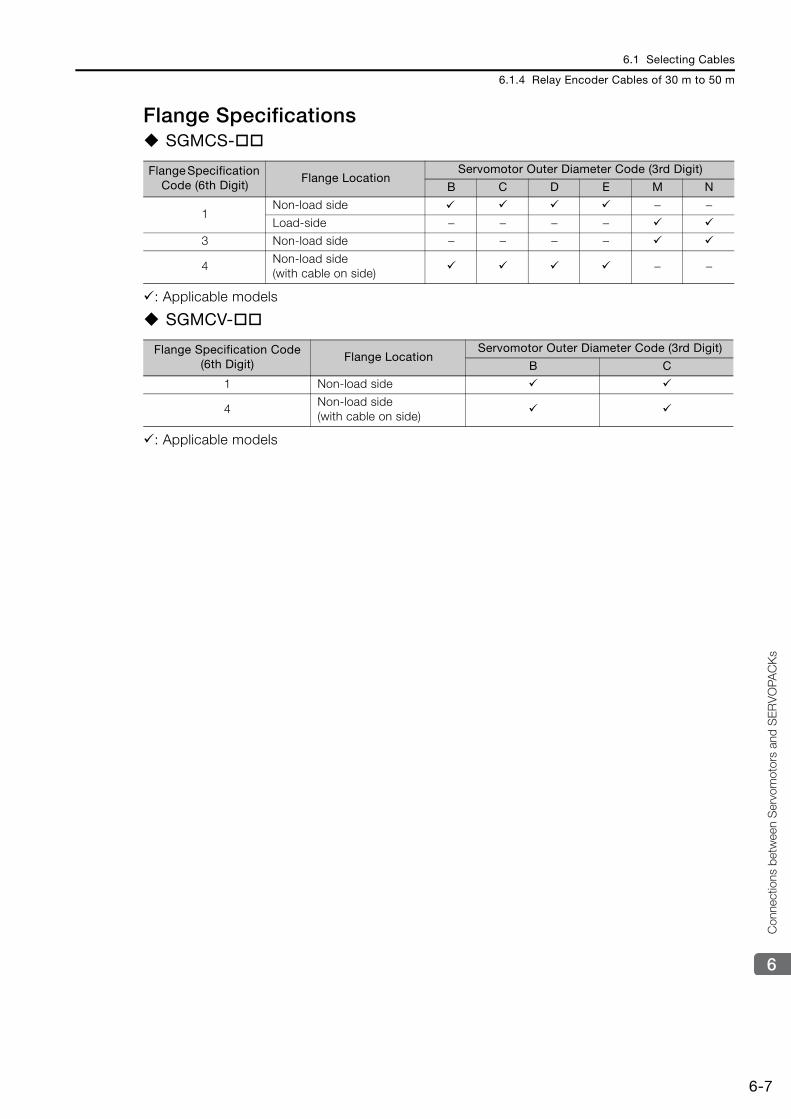
6.1 Selecting Cables
6.1.4 Relay Encoder Cables of 30 m to 50 m
6-7
6
Con
nect
ions
bet
wee
n S
ervo
mot
ors
and
SE
RV
OPA
CK
s
Flange SpecificationsSGMCS-
: Applicable models
SGMCV-
: Applicable models
Flange Specification Code (6th Digit)
Flange LocationServomotor Outer Diameter Code (3rd Digit)
B C D E M N
1Non-load side − −Load-side − − − −
3 Non-load side − − − −
4Non-load side (with cable on side)
− −
Flange Specification Code (6th Digit)
Flange LocationServomotor Outer Diameter Code (3rd Digit)
B C
1 Non-load side
4Non-load side (with cable on side)
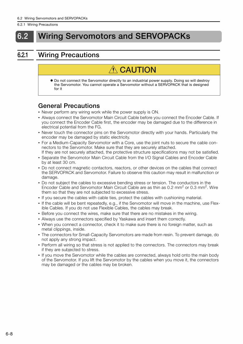
6.2 Wiring Servomotors and SERVOPACKs
6.2.1 Wiring Precautions
6-8
6.2 Wiring Servomotors and SERVOPACKs
6.2.1 Wiring Precautions
General Precautions• Never perform any wiring work while the power supply is ON. • Always connect the Servomotor Main Circuit Cable before you connect the Encoder Cable. If
you connect the Encoder Cable first, the encoder may be damaged due to the difference in electrical potential from the FG.
• Never touch the connector pins on the Servomotor directly with your hands. Particularly the encoder may be damaged by static electricity.
• For a Medium-Capacity Servomotor with a Core, use the joint nuts to secure the cable con-nectors to the Servomotor. Make sure that they are securely attached.If they are not securely attached, the protective structure specifications may not be satisfied.
• Separate the Servomotor Main Circuit Cable from the I/O Signal Cables and Encoder Cable by at least 30 cm.
• Do not connect magnetic contactors, reactors, or other devices on the cables that connect the SERVOPACK and Servomotor. Failure to observe this caution may result in malfunction or damage.
• Do not subject the cables to excessive bending stress or tension. The conductors in the Encoder Cable and Servomotor Main Circuit Cable are as thin as 0.2 mm2 or 0.3 mm2. Wire them so that they are not subjected to excessive stress.
• If you secure the cables with cable ties, protect the cables with cushioning material.• If the cable will be bent repeatedly, e.g., if the Servomotor will move in the machine, use Flex-
ible Cables. If you do not use Flexible Cables, the cables may break.• Before you connect the wires, make sure that there are no mistakes in the wiring.• Always use the connectors specified by Yaskawa and insert them correctly.• When you connect a connector, check it to make sure there is no foreign matter, such as
metal clippings, inside.• The connectors for Small-Capacity Servomotors are made from resin. To prevent damage, do
not apply any strong impact.• Perform all wiring so that stress is not applied to the connectors. The connectors may break
if they are subjected to stress.• If you move the Servomotor while the cables are connected, always hold onto the main body
of the Servomotor. If you lift the Servomotor by the cables when you move it, the connectors may be damaged or the cables may be broken.
CAUTIONDo not connect the Servomotor directly to an industrial power supply. Doing so will destroy the Servomotor. You cannot operate a Servomotor without a SERVOPACK that is designed for it
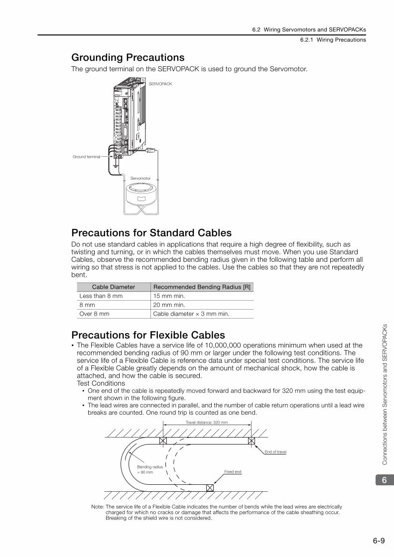
6.2 Wiring Servomotors and SERVOPACKs
6.2.1 Wiring Precautions
6-9
6
Con
nect
ions
bet
wee
n S
ervo
mot
ors
and
SE
RV
OPA
CK
s
Grounding PrecautionsThe ground terminal on the SERVOPACK is used to ground the Servomotor.
Precautions for Standard CablesDo not use standard cables in applications that require a high degree of flexibility, such as twisting and turning, or in which the cables themselves must move. When you use Standard Cables, observe the recommended bending radius given in the following table and perform all wiring so that stress is not applied to the cables. Use the cables so that they are not repeatedly bent.
Precautions for Flexible Cables• The Flexible Cables have a service life of 10,000,000 operations minimum when used at the
recommended bending radius of 90 mm or larger under the following test conditions. The service life of a Flexible Cable is reference data under special test conditions. The service life of a Flexible Cable greatly depends on the amount of mechanical shock, how the cable is attached, and how the cable is secured.Test Conditions
• One end of the cable is repeatedly moved forward and backward for 320 mm using the test equip-ment shown in the following figure.
• The lead wires are connected in parallel, and the number of cable return operations until a lead wire breaks are counted. One round trip is counted as one bend.
Note: The service life of a Flexible Cable indicates the number of bends while the lead wires are electrically charged for which no cracks or damage that affects the performance of the cable sheathing occur. Breaking of the shield wire is not considered.
Cable Diameter Recommended Bending Radius [R]
Less than 8 mm 15 mm min.
8 mm 20 mm min.
Over 8 mm Cable diameter × 3 mm min.
SERVOPACK
Servomotor
Ground terminal
Travel distance: 320 mm
Bending radius = 90 mm Fixed end
End of travel
6.2 Wiring Servomotors and SERVOPACKs
6.2.2 Wiring Procedure
6-10
• Straighten out the Flexible Cable when you connect it. If the cable is connected while it is twisted, it will break faster. Check the indication on the cable surface to make sure that the cable is not twisted.
• Do not secure the portions of the Flexible Cable that move. Stress will accumulate at the point that is secured, and the cable will break faster. Secure the cable in as few locations as possible.
• If a Flexible Cable is too long, looseness will cause it to break faster. It the Flexible Cable is too short, stress at the points where it is secured will cause it to break faster. Adjust the cable length to the optimum value.
• Do not allow Flexible Cables to interfere with each other. Interference will restrict the motion of the cables, causing them to break faster. Separate the cables sufficiently, or provide parti-tions between them when wiring.
6.2.2 Wiring ProcedureWire according to the figure on the following page.
6.1.1 System Configurations on page 6-2
Refer to the SERVOPACK manual for information on wiring the SERVOPACKs.
This chapter describes the maintenance, inspection, and disposal of a Servomotor.
7.1 Periodic Inspections . . . . . . . . . . . . . . . . . . 7-2
7.2 Service Lives of Parts . . . . . . . . . . . . . . . . . 7-3
7.3 Disposing of Servomotors . . . . . . . . . . . . . . 7-4
Maintenance and Inspection 7
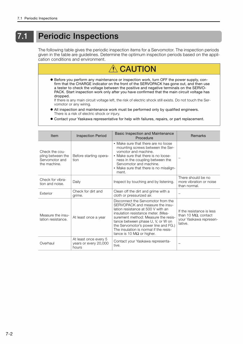
7.1 Periodic Inspections
7-2
7.1 Periodic Inspections
The following table gives the periodic inspection items for a Servomotor. The inspection periods given in the table are guidelines. Determine the optimum inspection periods based on the appli-cation conditions and environment.
CAUTIONBefore you perform any maintenance or inspection work, turn OFF the power supply, con-firm that the CHARGE indicator on the front of the SERVOPACK has gone out, and then use a tester to check the voltage between the positive and negative terminals on the SERVO-PACK. Start inspection work only after you have confirmed that the main circuit voltage has dropped.If there is any main circuit voltage left, the risk of electric shock still exists. Do not touch the Ser-vomotor or any wiring.All inspection and maintenance work must be performed only by qualified engineers.There is a risk of electric shock or injury.Contact your Yaskawa representative for help with failures, repairs, or part replacement.
Item Inspection PeriodBasic Inspection and Maintenance
ProcedureRemarks
Check the cou-pling between the Servomotor and the machine.
Before starting opera-tion
• Make sure that there are no loose mounting screws between the Ser-vomotor and machine.
• Make sure that there is no loose-ness in the coupling between the Servomotor and machine.
• Make sure that there is no misalign-ment.
−
Check for vibra-tion and noise. Daily Inspect by touching and by listening.
There should be no more vibration or noise than normal.
Exterior Check for dirt and grime.
Clean off the dirt and grime with a cloth or pressurized air. −
Measure the insu-lation resistance. At least once a year
Disconnect the Servomotor from the SERVOPACK and measure the insu-lation resistance at 500 V with an insulation resistance meter. (Mea-surement method: Measure the resis-tance between phase U, V, or W on the Servomotor’s power line and FG.)The insulation is normal if the resis-tance is 10 MΩ or higher.
If the resistance is less than 10 MΩ, contact your Yaskawa represen-tative.
OverhaulAt least once every 5 years or every 20,000 hours
Contact your Yaskawa representa-tive. −
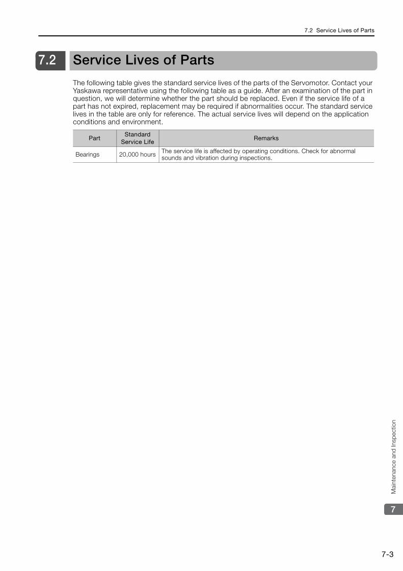
7.2 Service Lives of Parts
7-3
7
Mai
nten
ance
and
Insp
ectio
n
7.2 Service Lives of Parts
The following table gives the standard service lives of the parts of the Servomotor. Contact your Yaskawa representative using the following table as a guide. After an examination of the part in question, we will determine whether the part should be replaced. Even if the service life of a part has not expired, replacement may be required if abnormalities occur. The standard service lives in the table are only for reference. The actual service lives will depend on the application conditions and environment.
PartStandard
Service LifeRemarks
Bearings 20,000 hours The service life is affected by operating conditions. Check for abnormal sounds and vibration during inspections.

7.3 Disposing of Servomotors
7-4
7.3 Disposing of Servomotors
When disposing of a Servomotor, treat it as ordinary industrial waste.However, local ordinances and national laws must be observed. Implement all labeling and warnings as a final product as required.

The appendix provides information to use when selecting Servomotor capacities.
8.1 Reference Information for Servomotor Capacity Selection 8-28.1.1 GD2 for Simple Diagrams . . . . . . . . . . . . . . . . . . 8-28.1.2 Conversions between Traditional Units and
SI Units . . . . . . . . . . . . . . . . . . . . . . . . . . . . . . . . 8-3
Appendix 8
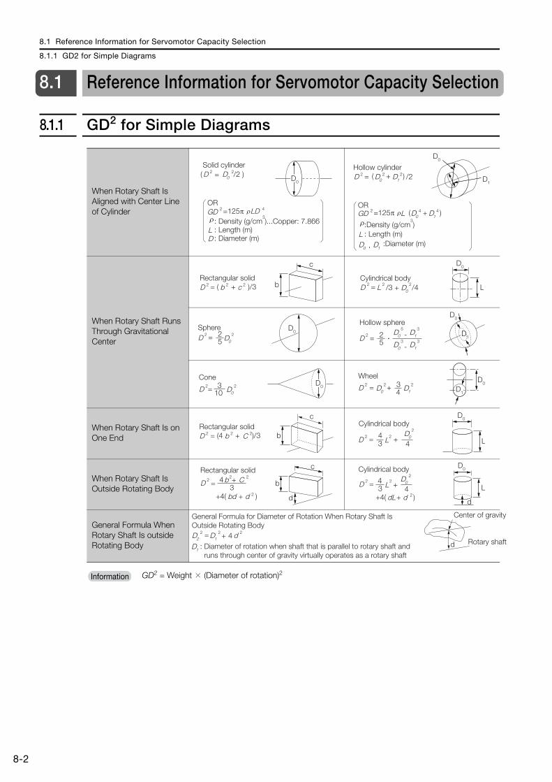
8.1 Reference Information for Servomotor Capacity Selection
8.1.1 GD2 for Simple Diagrams
8-2
8.1 Reference Information for Servomotor Capacity Selection
8.1.1 GD2 for Simple Diagrams
When Rotary Shaft Is Aligned with Center Line of Cylinder
When Rotary Shaft Runs Through Gravitational Center
When Rotary Shaft Is on One End
When Rotary Shaft Is Outside Rotating Body
General Formula When Rotary Shaft Is outside Rotating Body
GD2 = Weight × (Diameter of rotation)2
Solid cylinder
OR
: Density (g/cm3)...Copper: 7.866
: Length (m)
( = /2 )
=125π
D
GD
L: Diameter (m)D
D0 D0
2
2 4
2
ρρ
LD
Hollow cylinder
OR
:Density (g/cm3)
: Length (m)
= /2
=125π
D
GD
L:Diameter (m)
D02
2
2 D12
D04 D1
4ρ
ρ
( + )
( + )L
D0 D1,
D0
D1
= ( + )/3Rectangular solidD b bc
c
2 2 2 = /3 + /4Cylindrical bodyD L LD0
D0
2 2 2
52
D0
=SphereD D0
2 2
D0
D1= -
Hollow sphere
52D 2 D0
5D1
3
-D0
3D1
3�
D0
103=
Cone
D D0
2 2D0
D1+
43=
Wheel
D D0
2 2D1
2
c
bC= (4 + )/3Rectangular solidD b2 2 2
D0
= +
Cylindrical body
L L34
4D 2 2 D0
2
b
d
b
bd d
c
C=
+4( + )
Rectangular solid
34 +D 2
2 2
2
D0
LLD0+4
dL dd
=
+4( + )
Cylindrical body
34D 2
2
22
d
Center of gravity
Rotary shaft: Diameter of rotation when shaft that is parallel to rotary shaft and runs through center of gravity virtually operates as a rotary shaft
General Formula for Diameter of Rotation When Rotary Shaft Is Outside Rotating Body
= + 4D2
2 D1
2 2d
D1
Information
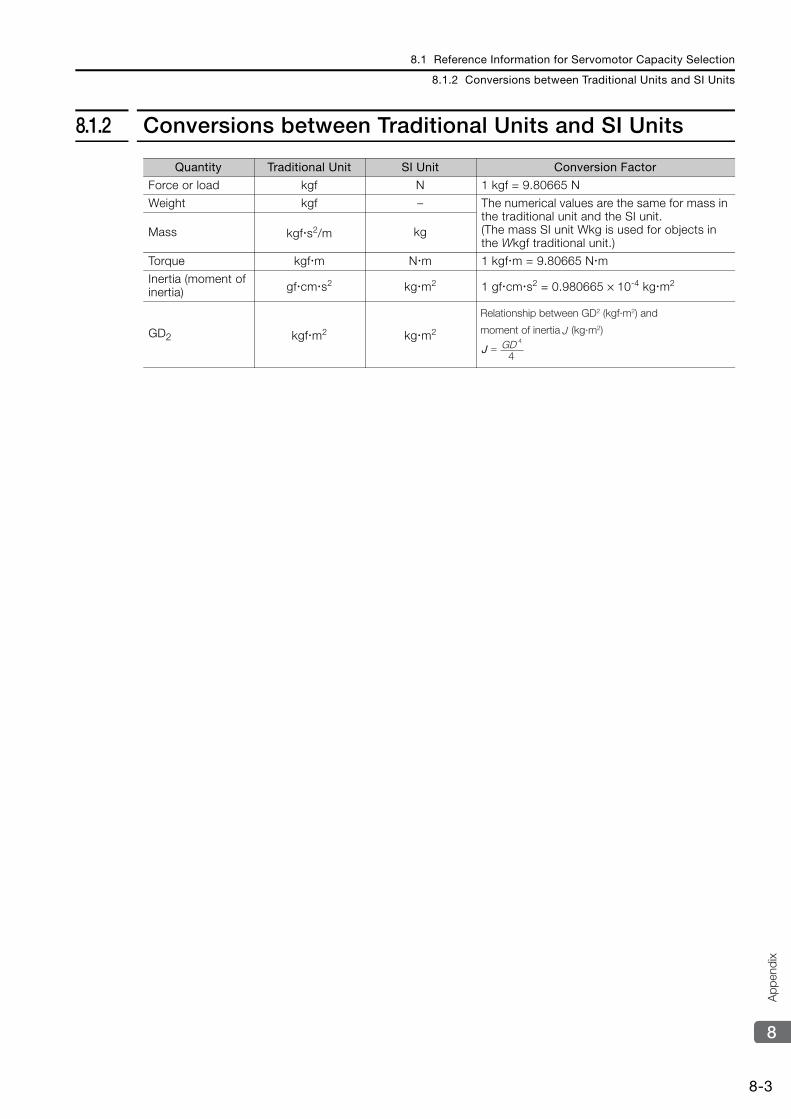
8.1 Reference Information for Servomotor Capacity Selection
8.1.2 Conversions between Traditional Units and SI Units
8-3
8
App
endi
x
8.1.2 Conversions between Traditional Units and SI Units
Quantity Traditional Unit SI Unit Conversion Factor
Force or load kgf N 1 kgf = 9.80665 N
Weight kgf – The numerical values are the same for mass in the traditional unit and the SI unit.(The mass SI unit Wkg is used for objects in the Wkgf traditional unit.)
Mass kgf s2/m kg
Torque kgf m N m 1 kgf m = 9.80665 N m
Inertia (moment of inertia) gf cm s2 kg m2 1 gf cm s2 = 0.980665 × 10⁻⁴ kg m2
GD2 kgf m2 kg m2
Relationship between GD2 (kgf·m2) and
moment of inertia (kg·m2)
=J GD4
J4
J
Revision History-1
Revision History
The revision dates and numbers of the revised manuals are given on the bottom of the back cover.
Date of Publication
Rev. No. Section Revised Content
April 2014 − − First edition
MANUAL NO. SIEP S800001 38A
Published in Japan April 2014 14-4
Date of publication
Date of original publication
IRUMA BUSINESS CENTER (SOLUTION CENTER)480, Kamifujisawa, Iruma, Saitama 358-8555, JapanPhone 81-4-2962-5151 Fax 81-4-2962-6138http://www.yaskawa.co.jp
YASKAWA AMERICA, INC.2121 Norman Drive South, Waukegan, IL 60085, U.S.A.Phone 1-800-YASKAWA (927-5292) or 1-847-887-7000 Fax 1-847-887-7310http://www.yaskawa.com
YASKAWA ELÉTRICO DO BRASIL LTDA.Avenida Piraporinha 777, Diadema, São Paulo, 09950-000, Brasil Phone 55-11-3585-1100 Fax 55-11-3585-1187http://www.yaskawa.com.br
YASKAWA EUROPE GmbHHauptstraβe 185, Eschborn 65760, GermanyPhone 49-6196-569-300 Fax 49-6196-569-398http://www.yaskawa.eu.com
YASKAWA ELECTRIC KOREA CORPORATION9F, Kyobo Securities Bldg. 26-4, Yeouido-dong, Yeongdeungpo-gu, Seoul, 150-737, KoreaPhone 82-2-784-7844 Fax 82-2-784-8495http://www.yaskawa.co.kr
YASKAWA ELECTRIC (SINGAPORE) PTE. LTD.151 Lorong Chuan, #04-02A, New Tech Park 556741, SingaporePhone 65-6282-3003 Fax 65-6289-3003http://www.yaskawa.com.sg
YASKAWA ELECTRIC (CHINA) CO., LTD.12F, Carlton Bld., No.21 HuangHe Road, HuangPu District, Shanghai 200003, ChinaPhone 86-21-5385-2200 Fax 86-21-5385-3299http://www.yaskawa.com.cn
YASKAWA ELECTRIC (CHINA) CO., LTD. BEIJING OFFICERoom 1011, Tower W3 Oriental Plaza, No.1 East Chang An Ave.,Dong Cheng District, Beijing 100738, ChinaPhone 86-10-8518-4086 Fax 86-10-8518-4082
YASKAWA ELECTRIC TAIWAN CORPORATION9F, 16, Nanking E. Rd., Sec. 3, Taipei 104, TaiwanPhone 886-2-2502-5003 Fax 886-2-2505-1280
In the event that the end user of this product is to be the military and said product is to be employed in any weapons systems or the manufacture thereof, the export will fall under the relevant regulations as stipulated in the Foreign Exchange and Foreign Trade Regulations. Therefore, be sure to follow all procedures and submit all relevant documentation according to any and all rules, regulations and laws that may apply.
Specifications are subject to change without notice for ongoing product modifications and improvements.
© 2014 YASKAWA ELECTRIC CORPORATION. All rights reserved.
Published in Japan April 2014 14-4
MANUAL NO. SIEP S800001 38A
13-6-9Original instructions
YASKAWA ELECTRIC CORPORATION
Direct Drive ServomotorΣ-7-Series AC Servo Drive
Product Manual


![5054415D003 Ixengo L - Somfy · PT Manual de instalação ... Check that the motor drive unit E is horizontally aligned using a spirit level. [7] Attach the gate section mounting](https://static.fdocument.org/doc/165x107/5c0302a509d3f2ab198c5510/5054415d003-ixengo-l-somfy-pt-manual-de-instalacao-check-that-the-motor.jpg)