SHIMANO 105 Front Derailleur for Triple Gear FD … 105 Front Derailleur for Triple Gear FD-5703-S...
4
SHIMANO 105 Front Derailleur for Triple Gear FD-5703-S Silver Version FD-5703-L Black Version ITEM NO. 1 Y5MR98010 Stroke Adjust Screws (M4 x 13) & Plate 2 Y5LW98020 Cable Fixing Plate & Bolt (M5 x 8) A 3 Y5A407020 Clamp Bolt (M5 x 15) A A 4 Y5JD98020 Clamp Band Adapter (2 pcs.) for S-size / φ28.6 mm (1-1/8”) A A 5 Y5JD98030 Clamp Bolt (M5 x 13.5) & Radius Washer for Brazed-on Type A 6 Y58032000 SM-FD74 Brazed-on Bracket A A 7 Y58032100 SM-FD74-LW Brazed-on Bracket (Investment Cast) A A 8 Y5JD98040 SM-AD11 Clamp Band Unit φ31.8 mm (1-1/4”) for Brazed-on Type A 9 Y5JD98050 SM-AD15 Clamp Band Unit φ34.9 mm (1-3/8”) for Brazed-on Type A 10 Y59L19100 Clamp Bolt (M5 x 17.5) for SM-AD11 / AD15 A 11 Y5C252000 Clamp Bolt (M5 x 13.5) for SM-AD11 / AD15 A A A: Same parts. Mar.-2010-3053 B: Parts are usable, but differ in materirals, appearance, finish, size, etc. © Shimano Inc. A Absence of mark indicates non-interchangeability. Specifications are subject to change without notice. INTERCHANGEABILITY SHIMANO CODE NO. DESCRIPTION FD- 670 3 FD- 560 3
Transcript of SHIMANO 105 Front Derailleur for Triple Gear FD … 105 Front Derailleur for Triple Gear FD-5703-S...
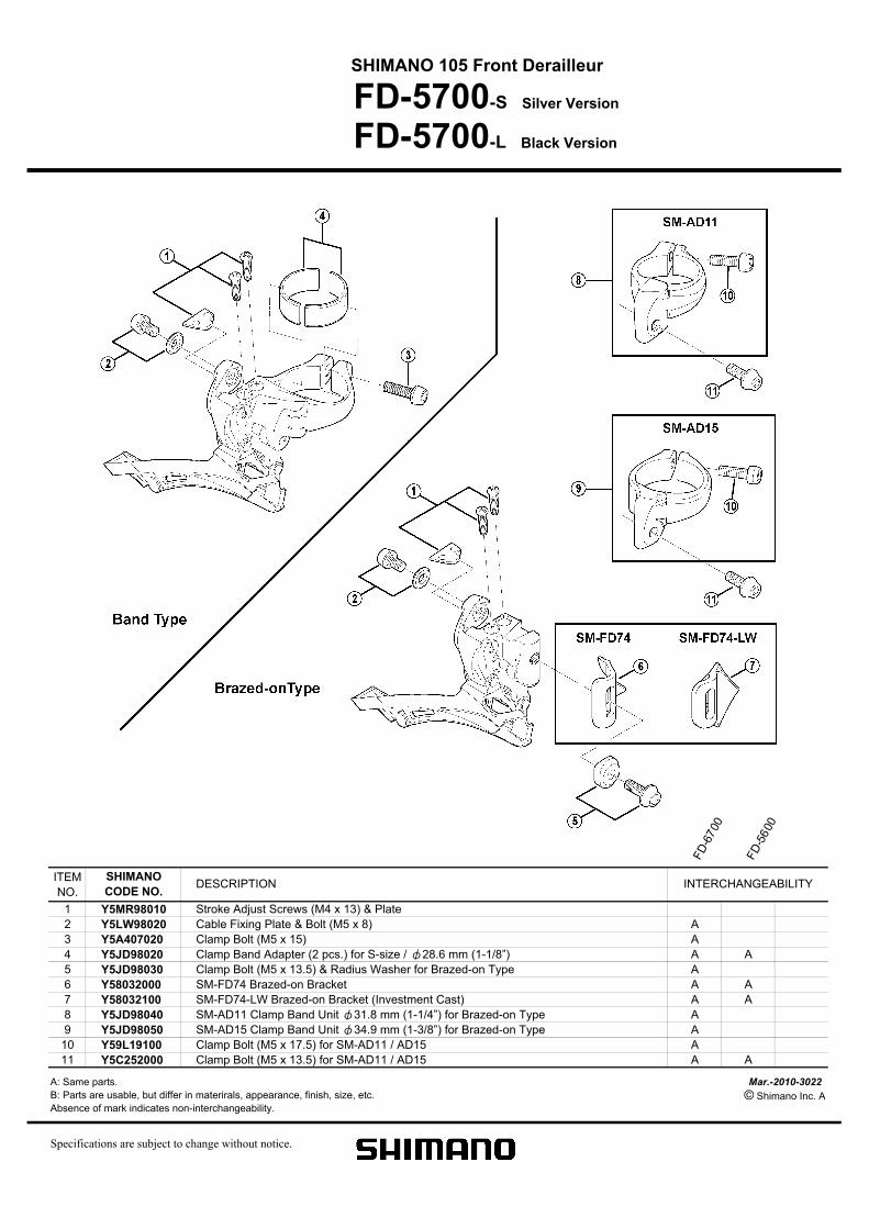
SHIMANO 105 Front Derailleur for Triple Gear
FD-5703-S Silver Version
FD-5703-L Black Version
ITEM
NO.
1 Y5MR98010 Stroke Adjust Screws (M4 x 13) & Plate
2 Y5LW98020 Cable Fixing Plate & Bolt (M5 x 8) A
3 Y5A407020 Clamp Bolt (M5 x 15) A A
4 Y5JD98020 Clamp Band Adapter (2 pcs.) for S-size / φ28.6 mm (1-1/8”) A A
5 Y5JD98030 Clamp Bolt (M5 x 13.5) & Radius Washer for Brazed-on Type A
6 Y58032000 SM-FD74 Brazed-on Bracket A A
7 Y58032100 SM-FD74-LW Brazed-on Bracket (Investment Cast) A A
8 Y5JD98040 SM-AD11 Clamp Band Unit φ31.8 mm (1-1/4”) for Brazed-on Type A
9 Y5JD98050 SM-AD15 Clamp Band Unit φ34.9 mm (1-3/8”) for Brazed-on Type A
10 Y59L19100 Clamp Bolt (M5 x 17.5) for SM-AD11 / AD15 A
11 Y5C252000 Clamp Bolt (M5 x 13.5) for SM-AD11 / AD15 A A
A: Same parts. Mar.-2010-3053
B: Parts are usable, but differ in materirals, appearance, finish, size, etc. © Shimano Inc. A
Absence of mark indicates non-interchangeability.
Specifications are subject to change without notice.
INTERCHANGEABILITYSHIMANO
CODE NO.DESCRIPTION
FD
- 670
3
FD
- 560
3
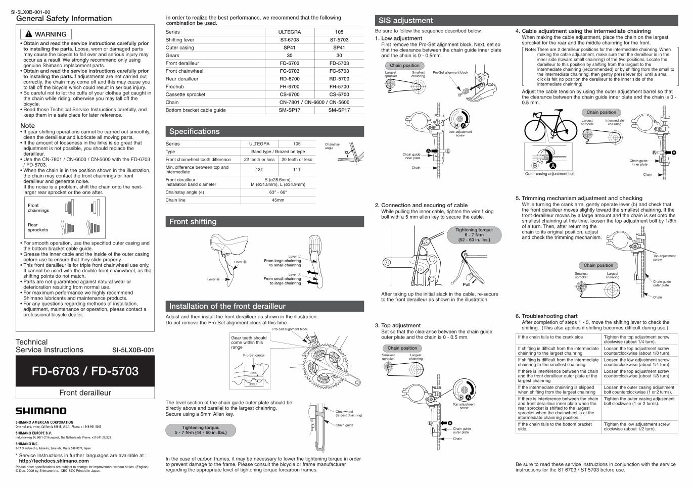
5. Trimming mechanism adjustment and checkingWhile turning the crank arm, gently operate lever (b) and check thatthe front derailleur moves slightly toward the smallest chainring. If thefront derailleur moves by a large amount and the chain is set onto thesmallest chainring at this time, loosen the top adjustment bolt by 1/8thof a turn. Then, after returning thechain to its original position, adjustand check the trimming mechanism.
General Safety Information
WARNING
• Obtain and read the service instructions carefully priorto installing the parts. Loose, worn or damaged partsmay cause the bicycle to fall over and serious injury mayoccur as a result. We strongly recommend only usinggenuine Shimano replacement parts.
• Obtain and read the service instructions carefully priorto installing the parts.If adjustments are not carried outcorrectly, the chain may come off and this may cause youto fall off the bicycle which could result in serious injury.
• Be careful not to let the cuffs of your clothes get caught inthe chain while riding, otherwise you may fall off thebicycle.
• Read these Technical Service Instructions carefully, andkeep them in a safe place for later reference.
Note• If gear shifting operations cannot be carried out smoothly,
clean the derailleur and lubricate all moving parts.• If the amount of looseness in the links is so great that
adjustment is not possible, you should replace thederailleur.
• Use the CN-7801 / CN-6600 / CN-5600 with the FD-6703/ FD-5703.
• When the chain is in the position shown in the illustration,the chain may contact the front chainrings or frontderailleur and generate noise.If the noise is a problem, shift the chain onto the next-larger rear sprocket or the one after.
• For smooth operation, use the specified outer casing andthe bottom bracket cable guide.
• Grease the inner cable and the inside of the outer casingbefore use to ensure that they slide properly.
• This front derailleur is for triple front chainwheel use only.It cannot be used with the double front chainwheel, as theshifting points do not match.
• Parts are not guaranteed against natural wear ordeterioration resulting from normal use.
• For maximum performance we highly recommendShimano lubricants and maintenance products.
• For any questions regarding methods of installation,adjustment, maintenance or operation, please contact aprofessional bicycle dealer.
Frontchainrings
Rearsprockets
In order to realize the best performance, we recommend that the followingcombination be used.
* Service Instructions in further languages are available at :http://techdocs.shimano.com
Please note: specifications are subject to change for improvement without notice. (English)© Dec. 2009 by Shimano Inc. XBC SZK Printed in Japan.
Shifting lever
Series ULTEGRA
ST-6703
Outer casing SP41
Gears 30
Front derailleur FD-6703
Front chainwheel FC-6703
Rear derailleur RD-6700
Freehub FH-6700
Cassette sprocket CS-6700
Chain
Bottom bracket cable guide
CN-7801 / CN-6600 / CN-5600
SM-SP17
105
ST-5703
SP41
30
FD-5703
FC-5703
RD-5700
FH-5700
CS-5700
SM-SP17
Specifications
Installation of the front derailleur
Front shifting
Type Band type / Brazed on type
Series ULTEGRA 105
Front chainwheel tooth difference 22 teeth or less 20 teeth or less
Min. difference between top andintermediate
13T 11T
Front derailleur installation band diameter
S (ø28.6mm), M (ø31.8mm), L (ø34.9mm)
Chainstay angle (C) 63° - 66°
Chain line 45mm
Chainstayangle
Adjust and then install the front derailleur as shown in the illustration.
Do not remove the Pro-Set alignment block at this time.
1mm
3mm
Gear teeth shouldcome within thisrange
Pro-Set gauge
The level section of the chain guide outer plate should bedirectly above and parallel to the largest chainring.
Secure using a 5mm Allen key.Chainwheel(largest chainring)
Chain guideTightening torque:
5 - 7 N·m {44 - 60 in. lbs.}
SIS adjustment
Be sure to follow the sequence described below.
1. Low adjustmentFirst remove the Pro-Set alignment block. Next, set sothat the clearance between the chain guide inner plateand the chain is 0 - 0.5mm.
2. Connection and securing of cableWhile pulling the inner cable, tighten the wire fixingbolt with a 5 mm allen key to secure the cable.
3. Top adjustmentSet so that the clearance between the chain guideouter plate and the chain is 0 - 0.5 mm.
Largestsprocket
Smallestchainring
Chain position
Pro-Set alignment block
Pull
Tightening torque: 6 - 7 N·m
{52 - 60 in. lbs.}
After taking up the initial slack in the cable, re-secureto the front derailleur as shown in the illustration.
Smallestsprocket
Largestchainring
Chain position
4. Cable adjustment using the intermediate chainringWhen making the cable adjustment, place the chain on the largestsprocket for the rear and the middle chainring for the front.
Note: There are 2 derailleur positions for the intermediate chainring. Whenmaking the cable adjustment, make sure that the derailleur is in theinner side (toward small chainring) of the two positions. Locate thederailleur to this position by shifting from the largest to theintermediate chainring (recommended) or by shifting from the small tothe intermediate chainring, then gently press lever (b) until a smallclick is felt (to position the derailleur to the inner side of theintermediate chainring).
Adjust the cable tension by using the outer adjustment barrel so thatthe clearance between the chain guide inner plate and the chain is 0 -0.5 mm.
Largestsprocket
Intermediatechainring
B A
Outer casing adjustment bolt
Chain position
Chain guideinner plate
Top adjustmentscrew
Chain guideouter plate
Chain
Chain
Lever b
From large chainring to small chainring
Lever a
From small chainring to large chainring
Lever a
Lever b
Be sure to read these service instructions in conjunction with the serviceinstructions for the ST-6703 / ST-5703 before use.
Pro-Set alignment block
One Holland, Irvine, California 92618, U.S.A. Phone: +1-949-951-5003
Industrieweg 24, 8071 CT Nunspeet, The Netherlands Phone: +31-341-272222
3-77 Oimatsu-cho, Sakai-ku, Sakai-shi, Osaka 590-8577, Japan
Smallestsprocket
Largestchainring
Chain position
Low adjustmentscrew
Chain guideinner plate
Chain
Top adjustmentscrew
Chain guide outer plate
Chain
6. Troubleshooting chartAfter completion of steps 1 - 5, move the shifting lever to check theshifting. (This also applies if shifting becomes difficult during use.)
If the chain falls to the crank side
If shifting is difficult from the intermediatechainring to the largest chainring
If shifting is difficult from the intermediatechainring to the smallest chainring
If there is interference between the chainand the front derailleur outer plate at thelargest chainring
If the intermediate chainring is skippedwhen shifting from the largest chainring
If there is interference between the chainand front derailleur inner plate when therear sprocket is shifted to the largestsprocket when the chainwheel is at theintermediate chainring position.
If the chain falls to the bottom bracketside.
Tighten the top adjustment screwclockwise (about 1/4 turn).
Loosen the top adjustment screwcounterclockwise (about 1/8 turn).
Loosen the low adjustment screwcounterclockwise (about 1/4 turn).
Loosen the top adjustment screwcounterclockwise (about 1/8 turn).
Loosen the outer casing adjustmentbolt counterclockwise (1 or 2 turns).
Tighten the outer casing adjustmentbolt clockwise (1 or 2 turns).
Tighten the low adjustment screwclockwise (about 1/2 turn).
In the case of carbon frames, it may be necessary to lower the tightening torque in orderto prevent damage to the frame. Please consult the bicycle or frame manufacturerregarding the appropriate level of tightening torque forcarbon frames.
SI-5LX0B-001-00
FD-6703 / FD-5703
Front derailleur
Technical Service Instructions SI-5LX0B-001
SHIMANO 105 Front Derailleur
FD-5700-S Silver Version
FD-5700-L Black Version
ITEM
NO.
1 Y5MR98010 Stroke Adjust Screws (M4 x 13) & Plate
2 Y5LW98020 Cable Fixing Plate & Bolt (M5 x 8) A
3 Y5A407020 Clamp Bolt (M5 x 15) A
4 Y5JD98020 Clamp Band Adapter (2 pcs.) for S-size / φ28.6 mm (1-1/8”) A A
5 Y5JD98030 Clamp Bolt (M5 x 13.5) & Radius Washer for Brazed-on Type A
6 Y58032000 SM-FD74 Brazed-on Bracket A A
7 Y58032100 SM-FD74-LW Brazed-on Bracket (Investment Cast) A A
8 Y5JD98040 SM-AD11 Clamp Band Unit φ31.8 mm (1-1/4”) for Brazed-on Type A
9 Y5JD98050 SM-AD15 Clamp Band Unit φ34.9 mm (1-3/8”) for Brazed-on Type A
10 Y59L19100 Clamp Bolt (M5 x 17.5) for SM-AD11 / AD15 A
11 Y5C252000 Clamp Bolt (M5 x 13.5) for SM-AD11 / AD15 A A
A: Same parts. Mar.-2010-3022
B: Parts are usable, but differ in materirals, appearance, finish, size, etc. © Shimano Inc. A
Absence of mark indicates non-interchangeability.
Specifications are subject to change without notice.
INTERCHANGEABILITYSHIMANO
CODE NO.DESCRIPTION
FD
-6700
FD
-5600
2. The level section of the chain guide outer plate should bedirectly above and parallel to the largest chainring.
3. Secure using a 5mm Allen key.Chainwheel (largest chainring)
Chain guide
Tightening torque: 5 - 7 N·m
{44 - 60 in. lbs.}
3. Top adjustmentSet so that the clearance between the chain guide outerplate and the chain is 0 - 0.5 mm.
Tighten the top adjustment screw clockwise(about 1/4 turn).
Loosen the top adjustment screwcounterclockwise (about 1/8 turn).
Loosen the low adjustment screwcounterclockwise (about 1/8 turn).
Tighten the low adjustment screw clockwise(about 1/2 turn).
Turn the outer casing adjustment boltclockwise (1/8 of a turn at a time) untilshifting to the small chainring becomessmooth. Be careful not to turn the outercasing adjustment bolt too far at this time,otherwise shifting to the large chainring willbecome more difficult.
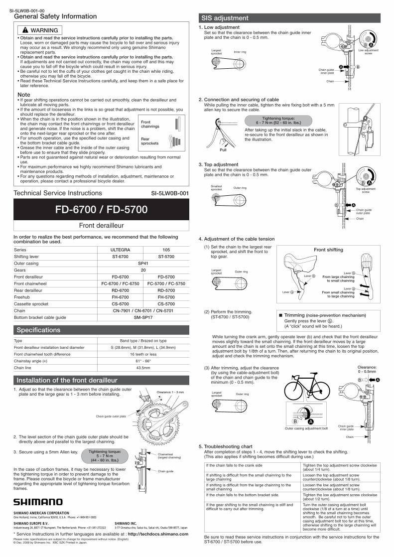
1. Adjust so that the clearance between the chain guide outerplate and the large gear is 1 - 3 mm before installing.
General Safety Information
• Obtain and read the service instructions carefully prior to installing the parts.Loose, worn or damaged parts may cause the bicycle to fall over and serious injurymay occur as a result. We strongly recommend only using genuine Shimanoreplacement parts.
• Obtain and read the service instructions carefully prior to installing the parts. If adjustments are not carried out correctly, the chain may come off and this maycause you to fall off the bicycle which could result in serious injury.
• Be careful not to let the cuffs of your clothes get caught in the chain while riding,otherwise you may fall off the bicycle.
• Read these Technical Service Instructions carefully, and keep them in a safe place forlater reference.
Note• If gear shifting operations cannot be carried out smoothly, clean the derailleur and
lubricate all moving parts.• If the amount of looseness in the links is so great that adjustment is not possible, you
should replace the derailleur.• When the chain is in the position shown in the illustration,
the chain may contact the front chainrings or front derailleurand generate noise. If the noise is a problem, shift the chainonto the next-larger rear sprocket or the one after.
• For smooth operation, use the specified outer casing andthe bottom bracket cable guide.
• Grease the inner cable and the inside of the outer casingbefore use to ensure that they slide properly.
• Parts are not guaranteed against natural wear or deterioration resulting from normaluse.
• For maximum performance we highly recommend Shimano lubricants andmaintenance products.
• For any questions regarding methods of installation, adjustment, maintenance oroperation, please contact a professional bicycle dealer.
WARNING
One Holland, Irvine, California 92618, U.S.A. Phone: +1-949-951-5003
Industrieweg 24, 8071 CT Nunspeet, The Netherlands Phone: +31-341-272222 3-77 Oimatsu-cho, Sakai-ku, Sakai-shi, Osaka 590-8577, Japan
* Service Instructions in further languages are available at : http://techdocs.shimano.comPlease note: specifications are subject to change for improvement without notice. (English)© Dec. 2009 by Shimano Inc. XBC SZK Printed in Japan.
SIS adjustment
1. Low adjustmentSet so that the clearance between the chain guide innerplate and the chain is 0 - 0.5 mm.
2. Connection and securing of cableWhile pulling the inner cable, tighten the wire fixing bolt with a 5 mmallen key to secure the cable.
While turning the crank arm, gently operate lever (b) and check that the front derailleurmoves slightly toward the small chainring. If the front derailleur moves by a largeamount and the chain is set onto the small chainring at this time, loosen the topadjustment bolt by 1/8th of a turn. Then, after returning the chain to its original position,adjust and check the trimming mechanism.
Largestsprocket
Inner ring
Smallestsprocket
Outer ring
Low adjustmentscrew
Chain guideinner plate
Chain
Pull
Tightening torque: 6 - 7 N·m {52 - 60 in. lbs.}
After taking up the initial slack in the cable,re-secure to the front derailleur as shown inthe illustration.
4. Adjustment of the cable tension
(1) Set the chain to the largest rearsprocket, and shift the front totop gear.
(2) Perform the trimming.
(ST-6700 / ST-5700)
(3) After trimming, adjust the clearance(by using the cable-adjustment bolt)of the chain and chain guide to theminimum (0 - 0.5 mm).
Top adjustmentscrew
Chain guide outer plate
Chain
■ Trimming (noise-prevention mechanism)
Gently press the lever [b .(A “click” sound will be heard.)
Chain guideinner plate
Chain
Clearance:0 - 0.5mm
B A
Be sure to read these service instructions in conjunction with the service instructions for theST-6700 / ST-5700 before use.
Outer casing adjustment bolt
Frontchainrings
Rearsprockets
Largestsprocket
Outer ring
Largestsprocket
Outer ring
Front shifting
Lever [bFrom large chainring
to small chainring
Lever [aFrom small chainring
to large chainring
Lever [a
Lever [b
Type Band type / Brazed on type
Front derailleur installation band diameter S (28.6mm), M (31.8mm), L (34.9mm)
Chainstay angle (C) 61° - 66°
Front chainwheel tooth difference 16 teeth or less
Chain line 43.5mm
In order to realize the best performance, we recommend that the followingcombination be used.
Series
Shifting lever
Outer casing
Gears
Front derailleur
Front chainwheel
Rear derailleur
Freehub
Cassette sprocket
Chain
Bottom bracket cable guide
Installation of the front derailleur
Clearance: 1 - 3 mm
Chain guide outer plate
Specifications
5. Troubleshooting chartAfter completion of steps 1 - 4, move the shifting lever to check the shifting.(This also applies if shifting becomes difficult during use.)
If the chain falls to the crank side
If shifting is difficult from the small chainring to thelarge chainring
If shifting is difficult from the large chainring to thesmall chainring
If the chain falls to the bottom bracket side.
If the gear shifting to the small chainring is stiff anddifficult to carry out after trimming.
In the case of carbon frames, it may be necessary to lowerthe tightening torque in order to prevent damage to theframe. Please consult the bicycle or frame manufacturerregarding the appropriate level of tightening torque forcarbonframes.
SI-5LW0B-001-00
Technical Service Instructions SI-5LW0B-001
FD-6700 / FD-5700
Front derailleur
ULTEGRA
ST-6700
SP41
20
FD-6700
FC-6700 / FC-6750
RD-6700
FH-6700
CS-6700
CN-7901 / CN-6701 / CN-5701
SM-SP17
105
ST-5700
FD-5700
FC-5700 / FC-5750
RD-5700
FH-5700
CS-5700


![[1] involuteΣ(Spur and Helical Gear Design) 1.3 Software ...Eng).pdf · [1] involuteΣ(Spur and Helical Gear Design) 1 t Fig..1.1 Calculation Result Screen 1.1 Introduction involute](https://static.fdocument.org/doc/165x107/5a7894b47f8b9a7b698d1836/1-involutespur-and-helical-gear-design-13-software-engpdf1-involutespur.jpg)