Security of Digital Systems - unipi.gr
68
Grigoris Valtas University of Piraeus Master Thesis September 2015 -1- University of Piraeus Department of Digital systems Postgraduate Programme: Security of Digital Systems Master Thesis SUBJECT : Exploiting Chronic Vulnerabilities in GSM by Using Commodity Hardware and Software Student Α.Μ Grigoris Valtas MTE1303 Supervisor Professor : Christos Xenakis
Transcript of Security of Digital Systems - unipi.gr
Grigoris Valtas University of Piraeus
Master Thesis September 2015 -1-
University of Piraeus Department of Digital systems
Postgraduate Programme:
Security of Digital Systems
Master Thesis
SUBJECT :
Exploiting Chronic Vulnerabilities in GSM by Using Commodity Hardware and Software
Student Α.Μ Grigoris Valtas MTE1303
Supervisor Professor : Christos Xenakis
Grigoris Valtas University of Piraeus
Master Thesis September 2015 -2-
1. Acknowledgements After completing this work, I would like to thank my two colleagues and friends Faidon and Nikos with whom we formed a great team during our MSc in University of Piraeus and started together the research and experiments on the area of security of mobile networks. I want also thank my two professors Mr. Xenakis and Mr. Dadoyan of University of Piraeus for the cooperation and their guidance during the authoring of the thesis.
Grigoris Valtas University of Piraeus
Master Thesis September 2015 -3-
2. Table of Content
1. Acknowledgements .................................................................................................. 2 2. Table of Contents ..................................................................................................... 3 3. Table of Figures ....................................................................................................... 5 4. TABLES ................................................................................................................... 6 5. General .................................................................................................................... 7 6. Aim and Objective of Thesis .................................................................................... 7 7. Introduction .............................................................................................................. 7
7.1 The background of Cellular Technology ............................................................. 8 8. GSM Overview ......................................................................................................... 9
8.1 Introduction to GSM ............................................................................................ 9 8.2 FDMA and TDMA Operation ............................................................................ 10 8.3 ARFCN (Absolut Radio Frequency Channel Number) ..................................... 10 8.4. GSM Numbering System - Identifiers .............................................................. 11
8.4.1. Mobile Subscriber ISDN (MSISDN) ......................................................... 11 8.4.2. International Mobile Subscriber Identity (IMSI) ......................................... 12 8.4.3. International Mobile Equipment Identity (IMEI) ......................................... 12 8.4.4. International Mobile Equipment Identity/Software Version (IMEISV) ........ 12
8.5. GSM Network Architecture .............................................................................. 13 8.5.1. MS (Mobile Station) .................................................................................. 13 8.5.2.Base Station Subsystem (BSS) ................................................................. 14 8.5.3. Network Subsystem (NSS) ....................................................................... 14
8.6. Signaling & Control Traffic ............................................................................... 16 8.7. Paging Procedure ............................................................................................ 17
8.7.1. Paging Procedure Techniques .................................................................. 18 8.7.2. Paging Procedure Analysis & Steps ......................................................... 18
8.8. TMSI in Local Areas ........................................................................................ 20 8.9. IMSI Transmission ........................................................................................... 21
9. AT Commands ....................................................................................................... 22 10. Testing Environment ............................................................................................ 23
10.1. Arduino .......................................................................................................... 23 10.2. RTL SDR / DVB-T TV Tuner ......................................................................... 26 10.2.1. RTL – SDR Radio Scanner Applications .................................................... 27
10.2.2. Software Defined Radio (SDR) ............................................................... 28 10.3. Open-source software tools .......................................................................... 28
It is important to mention that all the above tools are available in the Linux operating system. ............................................................................................... 28 10.3.1. Airprobe .................................................................................................. 28
11. RTL-SDR DVB-T TV Installation .......................................................................... 29 11.1. Kalibrate - RTL .............................................................................................. 29
12. System Information Message .............................................................................. 32 13. Paging Request Message .................................................................................... 33 14. Immediate Assignment Message ......................................................................... 34
Grigoris Valtas University of Piraeus
Master Thesis September 2015 -4-
15. Preliminary Measurements .................................................................................. 36 16. GSM Vulnerabilities .............................................................................................. 37
16.1. Poor Identity Confidentiality ........................................................................... 37 16.2. Unencrypted Signaling & Control Traffic ....................................................... 38 16.3. Poor TMSI Frequency change ....................................................................... 38 16.4. Fall back to GPRS/EDGE of UMTS/HSPA (3G, 3.5G) .................................. 39
17. A Stealthy denial of service attack to Mobile Station ........................................... 40 17.1. Examining an original phone call ................................................................... 40 17.2. Denial of service attack analysis ................................................................... 41 17.3. Denial of service attack effectiveness ........................................................... 44
18. Users Location Area Leakage .............................................................................. 44 18.1. Discover the current LA of the MS ................................................................. 44 18.1.1. Constructing the threat model .................................................................... 45 18.1.2. Switching Network Mode ............................................................................ 46 18.1.3. PCCH Downlink Sniffing Analysis .............................................................. 48 18.2. Discover the current radio cell that MS is located ......................................... 52 18.2.1. Extending the threat model ......................................................................... 52 18.2.2. PCCH downlink - Time Analysis ................................................................. 53
19. Mitigation Techniques .......................................................................................... 57 19.1. Identities Encryption ...................................................................................... 57 19.2. Frequent TMSI Change ................................................................................. 57 19.3. Firewalls and Intrusion Detection Systems .................................................... 57
20. Signaling in newest cellular Technologies ........................................................... 58 20.1. UMTS Security: User Identity Confidentiality ................................................. 58 20.2. LTE Security: User Identity Confidentiality .................................................... 59
21. Commodity Hardware for UMTS sniffing .............................................................. 61 21.1. Arduino + 3G GPS Shield .............................................................................. 61 21.2. OpenBTS – UMTS ......................................................................................... 62
22. Conclusions ......................................................................................................... 63 23. Appendix .............................................................................................................. 64
23.1. GSM Numbering System ............................................................................... 64 23.2. RTL – SDR Installation .................................................................................. 64 23.3. Arduino Custom Scripts ................................................................................. 65
24. References ........................................................................................................... 67
Grigoris Valtas University of Piraeus
Master Thesis September 2015 -5-
3. Table of Figures Figure 1: Evolution of Cellular Technology ................................................................. 9 Figure 2: FDD – ARFCN ........................................................................................... 11 Figure 3: Mobile Station (MS) ................................................................................... 13 Figure 4: GSM Network Components ....................................................................... 16 Figure 5: Paging Procedure ...................................................................................... 20 Figure 6: Arduino Components ................................................................................. 24 Figure 7: Programing with Arduino iDE ..................................................................... 25 Figure 8: Arduino - GSM shield ................................................................................. 26 Figure 9: RTL-SDR DVB-T TV .................................................................................. 27 Figure 10: Kalibrate ................................................................................................... 30 Figure 11: Greek Mobile Operators – 2G Allocated spectrum .................................. 30 Figure 12: Greek Mobile Operators – MCC/MNC ..................................................... 31 Figure 13: RTL-SDR Operation ................................................................................. 31 Figure 14: Executing gsm-receive.py ........................................................................ 32 Figure 15: Paging Request Message - IMSI ............................................................. 35 Figure 16: Cell ID – LAI ............................................................................................. 35 Figure 17: Call Setup - Time Sequence .................................................................... 41 Figure 18: Example of Sketches ............................................................................... 42 Figure 19: Dial - Call Termination ............................................................................. 43 Figure 20: Serial Output ............................................................................................ 43 Figure 21: Paging Requests Origination ................................................................... 45 Figure 22: GSM only operation switch ...................................................................... 46 Figure 23: Kalibrate Results - Available BTS ............................................................ 47 Figure 24: TMSI: 0xcb1b8e21 155 times .................................................................. 49 Figure 25: TMSI: 0xcb1b8e21 at Packet No 188 ........................................................... 49 Figure 26:TMSI: 0xcb1b8e21 at Packet No 588 ....................................................... 50 Figure 27: TMSI: 0xcb1b8e21 at Packet No 6352 .................................................... 50 Figure 28: Top 10 Captured TMSI ............................................................................ 51 Figure 29: Sniffing the Immediate Assignments ....................................................... 53 Figure 30: Immediate Assignment messages ........................................................... 54 Figure 31: Paging - Immediate Assignments - Timestamps ..................................... 55 Figure 32: Paging - Immediate Assignment - Graph ................................................. 56 Figure 33: UMTS Architecture .................................................................................. 58 Figure 34: LTE Architecture ...................................................................................... 60 Figure 35: Arduino 3G shield .................................................................................... 62
Grigoris Valtas University of Piraeus
Master Thesis September 2015 -6-
4. TABLES
Table 1: BTS & BSC network operations ................................................................... 14 Table 2: AT Commands (IMSI, TMSI, LAC, CID) ....................................................... 23 Table 3: Test Bed Cost .............................................................................................. 23 Table 4: Preliminary Statistics .................................................................................... 36 Table 5: IMSI Sample ................................................................................................. 37 Table 6: Observations on GSM PCCH ....................................................................... 48 Table 7: Captured TMSI - Sample ............................................................................. 50 Table 8: Time Space Results ..................................................................................... 55
Grigoris Valtas University of Piraeus
Master Thesis September 2015 -7-
5. General During this thesis we demonstrate two different practical attacks on cellular mobile networks by using cheap and publicly available commodity hardware and software. These attacks come to exploit chronic and proven vulnerabilities in mobile cellular technology by targeting both users and network and highlight several fundamental weaknesses that exist on widely known GSM (Global System for Mobile Communications). First scenario determines a DoS attack that takes place on a specific mobile phone and the second one arising from an experiment for tracking the location of mobile users concluding in a total of their privacy. Finally, we present some security measures and mitigations followed by a brief on security mechanisms that endure on the latest in use cellular technologies like UMTS and LTE.
6. Aim and Objective of Thesis The aim and objective of this thesis is double. Firstly, produces knowledge base about publicly available on market equipment that can offer trusted solutions to mobile security researchers to perform penetration tests on mobile network infrastructures. Furthermore, it comes to underline the simplicity with a malicious actor by only having on its possession a set of low-cost equipment, can introduce an asymmetric threat to a large scale of users without the latter become aware of that being directed. Finally, our thesis points those proven vulnerabilities that exist over the years on the worldwide and old GSM network and the lack of security measures and mechanisms that could protect the GSM subscribers.
7. Introduction Today, Long Term Evolution (LTE) is being deployed globally and general the LTE subscriptions are predicted to reach 2.6 billion by 2019. Regarding the Universal Mobile Telecommunications System (UMTS), which is the mostly used cellular technology the latest years, the subscribers are over 3 billion worldwide. Despite the come of newer technologies and rapid migration to 4G networks, GSM remains the dominant cellular technology in many countries. In fact GSM-only subscriptions represent the largest share of mobile subscriptions today. As most new LTE devices are backwards compatible to GSM, the latter will not be replaced, but rather complement 3G and 4G connectivity, operating as a fallback mechanism. Additionally, due to the fact that pricing and current use of mobile phones is based on data consumption, a large number of subscribers switch their mobile phones to lower data rate networks in order to achieve lower costs. The early years, security evaluation and hacking on cellular technologies were difficult procedures due to the fact that necessary hardware and software for practical experiments were expensive or were available only to mobile operators to access their networks. That phenomenon was quite beneficial for them, since they were not aware or pressured to enhance their provided level of security. Additionally, it was quite hard to find ways to simulate, communicate and apply security metrics on cellular technology. Nowadays, with the emergence of widely available commodity hardware and open source software in combination with Software Defined Radio
Grigoris Valtas University of Piraeus
Master Thesis September 2015 -8-
(SDR) deployment for GSM hacking, allowing anyone to perform experiments in cellular networks in a cost-effective and flexible manner. The security of GSM networks has been extensively tested and analyzed in the literature over the years. Many works as well as the security industry have agreed in the fact that GSM security levels were low and malicious actors can exploit widely analyzed vulnerabilities that were “born” from GSM design. However in those works, security of GSM networks have been demonstrated only theoretically analyzing only the most “famous” weaknesses. In our thesis, are presented two different attacks targeting both the GSM network and its subscribers by using low-cost and widely available hardware/software. All the experiments took place by using RTL-SDR tool which is a sniffer for the GSM signals, as well as an Arduino combined with a GSM shield that is used as software programmable mobile phone. RTL-SDR is a quite cheap wideband SDR scanner that plays the role of a passive sniffer. It can be used in order to sniff and decode GSM signaling and control traffic over the air interface. Arduino is an open-source electronic platform and in combination with GSM Shield, it has the ability to connect with the GSM network and simulate original mobile phone operations. These scenarios ranged from sniffing the signaling traffic to tracking and performing a denial of service situation. The first attack come to exploit the absence of any security mechanism that could prevent DoS attacks that target the user equipment and the second one exploits the fundamental vulnerability found among the signaling communication of the GSM network. This vulnerability has to do with broadcast signaling messages that are transmitted unencrypted during a paging procedure. Those signaling messages carry on sensitive information like subscribers personal identities (IMSI – TMSI) that can reveal user’s current location (LAI) compromising its privacy. Location privacy attacks can also have impact in the latest cellular technologies like UMTS and LTE.
7.1 The background of Cellular Technology GSM (Global System for Mobile Communications or Group Special Mobile) was started to develop by European Telecommunications Standard Institute (ETSI) at 1982 as a European standard for digital cellular mobile communications. GSM came to replace the first commercial mobile networks which hade been deployed at the early years of 1980 and were known as 1G. GSM was first mobile network that deployed along with digital characteristics and is known as 2G. At the end of 1990s GPRS (General Packet Radio Service), or 2.5 G was designed and released. GPRS, which was a packet switching service, came to extend GSM capabilities and typically was the first network that introduced data transmission along wireless mobile technology. Changes to modulation techniques and channel coding brought the Enhanced Data rates for Global Evolution (EDGE). EDGE was an evolution of GSM achieving higher data rates throughput. EDGE was not an autonomous system but used the nodes of GSM/GPRS infrastructure. In the early 2000s, many standards came to offer optimized data rates. Among others, the Wideband Code Division Multiple Access (W-CDMA) technology was came and announced by 3GGP organization in combination with the Universal Mobile Telecommunication Systems (UMTS) standard. That new technology that was referred as 3G brought features including all-IP multimedia subsystem and network with much increased data rates than previous ones. UMTS and 3G standards also include High-Speed Packet

Grigoris Valtas University of Piraeus
Master Thesis September 2015 -9-
Access (HSPA) technology. HSPA is the combination of two mobile telephony networks High-Speed Downlink Packet Access (HSDPA) and High-Speed Uplink Packet Access (HSUPA) came to extend and improve the performance of the existing 3G networks utilizing better the WDCMA protocols. In the late of 2008 a further improved standard released and named as Evolved HSPA (HSPA+). In the middle of 2000s and more exactly at 2011, in the need of higher available bandwidth two new standards released from 3GPP, common named as 4G in the context of advanced cellular technology. That was the Long Term Evolution (LTE) and IEEE 802.16 (WiMAX). 4G technologies came to enhance the QoS of previous systems (3G), offering higher bandwidth, quite better spectrum efficiency and multiplied the data transmission rates based on and all-IP network architecture.
Figure 1: Evolution of Cellular Technology
8. GSM Overview
8.1 Introduction to GSM GSM (Global System for Mobile Communications) is a digital cellular technology that is thought to be the standard for mobile communications globally and the most widely used cellular technology over the last 30 years. GSM offers worldwide roaming and interconnection with any available GSM network. GSM came to replace 1G analog mobile networks and offered much higher capacity and better frequency utilization than previous ones. The existing GSM networks are more than 800 providing wireless cellular services to more than 215 countries globally. GSM subscriptions has the 82.4% percent of the global market of mobile communications serving more than 5 billion people across the planet. GSM trademark also belongs to GSM Association (GSMA). GSMA was formed in 1995 and is a trade group that represents network operators and related companies that use GSM technology and supports and promotes the GSM system. Those mobile network operators have signed roaming agreements with each other. Due to the fact the complete overview
Grigoris Valtas University of Piraeus
Master Thesis September 2015 -10-
and analysis of GSM network is not the main subject of this thesis, the description and the analysis of its structural elements will not as much detailed. Generally, GSM offers an important variety of services like:
Ø Voice communication
Ø Short message service (SMS)
Ø Call forwarding
Ø Fax
Ø Voice mail
8.2 FDMA and TDMA Operation GSM technology is based on both Frequency Division Multiple Access (FDMA) and Time Division Multiple Access (TDMA) transmission methods. There are several bands available in use from GSM network such as 450MHz, 850MHz, 900MHz, 1800MHz and 1900MHz. GSM radio interface operates in 900MHz and 1.8GHz band in Europe and in 850MHz and 1.9GHz in United States. There are also bands that include additional bands in order to increase the spectrum availability. These bands called Extended GSM (EGSM). Regarding the FDMA operation, GSM allocated spectrum is divided into individual carrier frequencies with 200KHz bandwidth each one. GSM also uses the Frequency Division Duplexing (FDD) method. Duplexing is the process of achieving two-way communications over a telecommunications channel. By this method each band has a different frequency range for the uplink (MS to BTS) and a different separate range for the downlink (BTS to MS). Uplink is thought to be transmission link with direction from mobile phone to transceiver stations and downlink the transmission link with direction starts from transceiver stations towards the mobile phone. Although GSM operates with FDD (separate frequencies for transmit and receive), the mobile station does not transmit and receive at the same time. A switch is used to toggle the antenna between the transmitter and receiver.
8.3 ARFCN (Absolut Radio Frequency Channel Number)
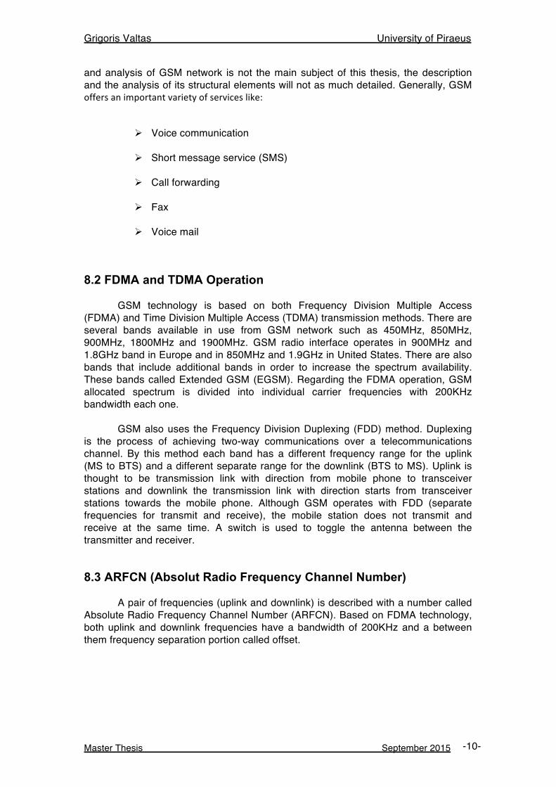
A pair of frequencies (uplink and downlink) is described with a number called Absolute Radio Frequency Channel Number (ARFCN). Based on FDMA technology, both uplink and downlink frequencies have a bandwidth of 200KHz and a between them frequency separation portion called offset.
Grigoris Valtas University of Piraeus
Master Thesis September 2015 -11-
Figure 2: FDD – ARFCN
Now based on the FDD operation, the two different frequencies that a mobile terminal transmits and receives are separated as fup (uplink frequency) and fdown (downlink frequency). The following is a way to calculate the uplink and downlink frequencies given the band, the ARFCN, and the offset.
GSM 900 Up = 890.0 + (ARFCN * .2) Down = Up + 45.0
8.4 GSM Numbering System - Identifiers
In this section is presented different portions that are being used in GSM for subscriber and mobile terminal recognition and identification.
8.4.1 Mobile Subscriber ISDN (MSISDN)
MSISDN is the network subscriber’s mobile phone number that anyone connected in GSM network can reach and dial in. The following composes the MSISDN:
Ø Country Code (CC): The country that the Mobile Station is registered to.
Ø National Destination Code (NDC): An absolute number that is
assigned to each PLMN.
Grigoris Valtas University of Piraeus
Master Thesis September 2015 -12-
Ø Subscriber Number (SN): The number assigned to the subscriber by the PLMN.
8.4.2 International Mobile Subscriber Identity (IMSI) IMSI is the identity that uniquely identified the subscriber within the GSM global network. The IMSI is composed of three parts:
Ø Mobile Country Code (MCC): Identifies from which country the subscriber’s network is in.
Ø Mobile Network Code (MNC): Identifies the home PLMN of the
subscriber.
Ø Mobile Subscriber Identification Number (MSIN): Identifies the user within the home GSM network.
8.4.3 International Mobile Equipment Identity (IMEI)
The IMEI identifies the Mobile Terminal itself. It is a serial number that is burned into the phone by the manufacturer. The IMEI is composed of the following three parts:
Ø Type Allocation Code (TAC): Identifies the model of the MT.
Ø Serial number (SNR): This numbers is a manufacturer-defined serial number of the MT.
Ø Spare (SP): This number is a check digit known as a Luhn Check
Digit and omitted during a GSM network transmission.
8.4.4 International Mobile Equipment Identity/Software Version (IMEISV)
IMEISV is a newer form of the IMEI that adds the Software Version Number (SVN) at the end. The SVN identifies the software version that the MT is using. The IMEISV is composed of the following three parts:
Ø Type Allocation Code (TAC): Identifies the model of the MT.
Ø Serial number (SNR): This numbers is a manufacturer-defined serial number of the MT.
Ø Software Version Number (SVN)
Grigoris Valtas University of Piraeus
Master Thesis September 2015 -13-
8.5 GSM Network Architecture
The GSM network consists of stable components and multiple interfaces such as transceivers, controllers and registers. We are focusing only on the network components relevant with our thesis subject.
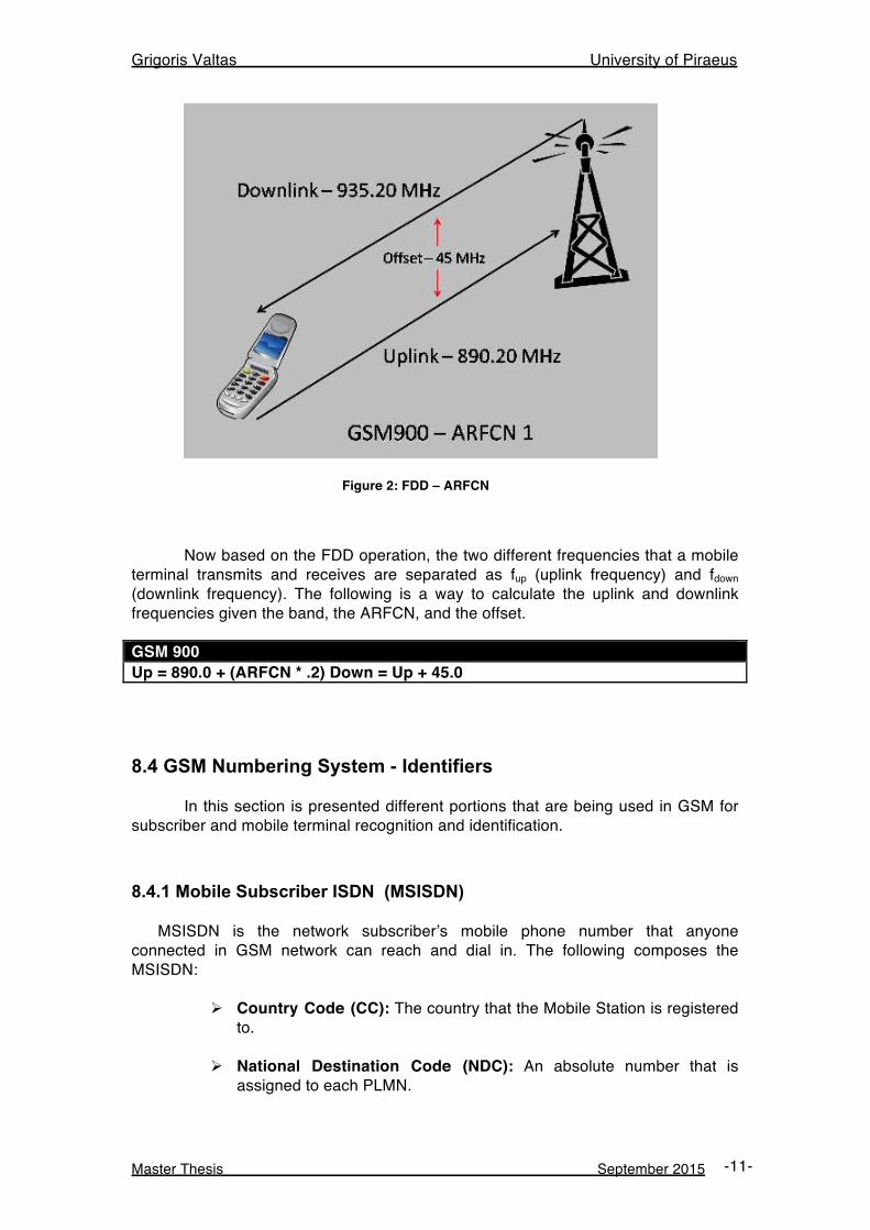
8.5.1 MS (Mobile Station)
A mobile station (MS) or user equipment (UE) is physical equipment that used from a subscriber to access the telecommunication services. The MS communicates with the Base Station Subsystem (BSS) over the Um interface. Um interface uses frequencies at 800/900 MHz and 1800/1900 MHz according to GSM specifications. Each MS has the following characteristics:
Ø Assigned a number of identification numbers that are referenced as identities.
Ø Identified by the International Mobile Equipment Identity (IMEI), which is persistently stored at Equipment Identity Register (EIR)
Every MS also carries the Subscriber Identity Module (SIM) that is used for subscriber identification and authentication between the subscriber and network. SIM card is integrated with a unique subscriber identity called International Mobile Subscriber Identity (IMSI). A 4-digit Personal Identification Number (PIN) protects SIM cards. In order to unlock a card, the user must enter the PIN. In case the user enter more than 3 times the PIN incorrectly, the card block itself and cannot be used. It can only by unlocked with an 8-digit Personal Unblocking Key (PUK), which is also stored on the SIM card.
Figure 3: Mobile Station (MS)
Grigoris Valtas University of Piraeus
Master Thesis September 2015 -14-
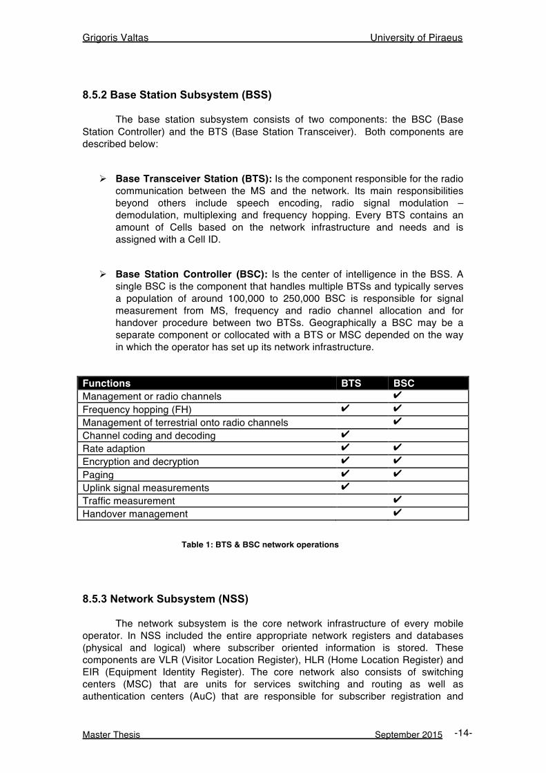
8.5.2 Base Station Subsystem (BSS) The base station subsystem consists of two components: the BSC (Base Station Controller) and the BTS (Base Station Transceiver). Both components are described below:
Ø Base Transceiver Station (BTS): Is the component responsible for the radio communication between the MS and the network. Its main responsibilities beyond others include speech encoding, radio signal modulation – demodulation, multiplexing and frequency hopping. Every BTS contains an amount of Cells based on the network infrastructure and needs and is assigned with a Cell ID.
Ø Base Station Controller (BSC): Is the center of intelligence in the BSS. A
single BSC is the component that handles multiple BTSs and typically serves a population of around 100,000 to 250,000 BSC is responsible for signal measurement from MS, frequency and radio channel allocation and for handover procedure between two BTSs. Geographically a BSC may be a separate component or collocated with a BTS or MSC depended on the way in which the operator has set up its network infrastructure.
Functions BTS BSC Management or radio channels ✔ Frequency hopping (FH) ✔ ✔ Management of terrestrial onto radio channels ✔ Channel coding and decoding ✔ Rate adaption ✔ ✔ Encryption and decryption ✔ ✔ Paging ✔ ✔ Uplink signal measurements ✔ Traffic measurement ✔ Handover management ✔
Table 1: BTS & BSC network operations
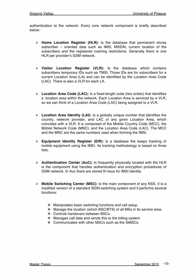
8.5.3 Network Subsystem (NSS) The network subsystem is the core network infrastructure of every mobile operator. In NSS included the entire appropriate network registers and databases (physical and logical) where subscriber oriented information is stored. These components are VLR (Visitor Location Register), HLR (Home Location Register) and EIR (Equipment Identity Register). The core network also consists of switching centers (MSC) that are units for services switching and routing as well as authentication centers (AuC) that are responsible for subscriber registration and
Grigoris Valtas University of Piraeus
Master Thesis September 2015 -15-
authentication to the network. Every core network component is briefly described below:
Ø Home Location Register (HLR): Is the database that permanent stores subscriber – oriented data such as IMSI, MSIDN, current location of the subscribers and the registered roaming restrictions. Generally there is one HLR per provider’s GSM network.
Ø Visitor Location Register (VLR): Is the database which contains
subscribers temporary IDs such as TMSI. Those IDs are for subscribers for a current Location Area (LA) and can be identified by the Location Area Code (LAC). There is also a VLR for each LA.
Ø Location Area Code (LAC): Is a fixed-length code (two octets) that identifies
a location area within the network. Each Location Area is serviced by a VLR, so we can think of a Location Area Code (LAC) being assigned to a VLR.
Ø Location Area Identity (LAI): Is a globally unique number that identifies the
country, network provider, and LAC of any given Location Area, which coincides with a VLR. It is composed of the Mobile Country Code (MCC), the Mobile Network Code (MNC), and the Location Area Code (LAC). The MCC and the MNC are the same numbers used when forming the IMSI.
Ø Equipment Identity Register (EIR): is a database the keeps tracking of
mobile equipment using the IMEI. Its tracking methodology is based on three lists.
Ø Authentication Center (AuC): Is frequently physically located with the HLR
is the component that handles authentication and encryption procedures of GSM network. In Auc there are stored Ki keys for IMSI identity.
Ø Mobile Switching Center (MSC): Is the main component of any NSS. It is a
modified version of a standard ISDN-switching system and it performs several functions:
v Manipulates basic switching functions and call setup. v Manage the location (which BSC/BTS) of all MSs in its service area. v Controls handovers between BSCs. v Manages call data and sends this to the billing system v Communicates with other MSCs such as the GMSCs.
Grigoris Valtas University of Piraeus
Master Thesis September 2015 -16-
Figure 4: GSM Network Components
8.6 Signaling & Control Traffic The MS - BTS communication takes place over the wireless GSM protocol, also known as Um interface. GSM uses multiple channels defined for the downlink and uplink communication that carry information over the radio link. These channels are divided in two main categories:
Ø Physical
Ø Logical A physical channel is determined by one or more carrier frequencies. Each carrier frequency includes the hopping sequence and the time slot. 8 Time Slots (1 Time Slot = 1 Physical Channel) of 577 µs constitutes a 4.615 ms TDMA Frame. In GSM standard data on a time slot transmitted in bursts, so time slot is often expressed in BP (Burst Period). 1 BP represents 1 TS. TDMA frame (4.615 ms of 8 TS) further structured in to multiframes. There are two types of multiframes in the system:
Ø 26 TDMA Multiframe: Consists 26 TDMA frames with duration of 120 ms and used to carry the Logical Channels TCH, SACCH, FACCH
Ø 51 TDMA Multiframe: Consists 51 TDMA frames with duration of 234.5 ms
and used to carry the Logical Channels FCCH, SCH, BCCH, CCCH, SDCCH, SACCH
Grigoris Valtas University of Piraeus
Master Thesis September 2015 -17-
Logical channels are used to carry both data and signaling traffic. Logical channels can be separated into traffic and signaling channels. Traffic channels transmit voice and data packets, while signaling channels carry control information allowing the system to operate correctly. During a regular phone communication different messages exchanged between the two sides using various logical control channels that have been defined both for uplink and downlink communication. Those channels operate both as broadcast and unicast. Logical control channels that are useful and relevant with this work are the following:
Ø Broadcast Control Channel (BCCH): Broadcast Control Channels is a group of downlink control channels that used for forwarding system information messages including cell specific information to the mobile stations like configuration, CELL-IDs, LA identifiers and LA codes.
Ø Paging Channel (PCH): The Paging Common Control channel is a broadcast
downlink channel that GSM network uses in order to locate and identify a mobile station.
Ø Random Access Channel (RACH): The Random Access Channel is a
point-to-point uplink channel that is used from every MS that tries to authenticate and request resources from the GSM network. A RACH could be characterized as response to a PCH message.
Ø Access Grant Control Channel (AGCH): The Access Grant Channel is a
point-to-point downlink control channel that is used for assigning resources to a mobile station that previously had requested access to the GSM network.
Ø Standalone Dedicated Control Channel (SDCCH): The Standalone
Dedicated Control Channel is a channel that used both from uplink and downlink communication. SDCCH is used in different procedures like carrying Immediate.
8.7 Paging Procedure
Paging procedure is one of the most fundamental procedures in the GSM network. Every time the network tries to discover the exact location of a MS in case of delivering GSM services (voice call, SMS), it performs the procedure of paging. During a paging procedure, signaling and control traffic is exchanged between the components of the network. Mobile network operators had to find an effective way for tracking their subscriber’s location regularly. That could help both them to deliver telecommunication services to their subscribers in a fast and direct way and also could help the network to decrease the utilization of radio resources. In order to serve the above purpose they implemented and performed the paging procedure in large geographical areas (LAs).
Grigoris Valtas University of Piraeus
Master Thesis September 2015 -18-
8.7.1 Paging Procedure Techniques GSM specifications include three different algorithms of paging procedure that depend on the geographical area range that messages of paging procedure transmitted and the rate at which the procedure repeated. Available algorithms that can be used in a paging procedure are the:
Ø Parallel: All the call of a particular LA paged simultaneously.
Ø Sequential: Cells in the coverage area are partitioned into groups and paged in a non-increasing order of user location probabilities, permits a reduction in the average radio costs of paging at the expense of greater delay in locating the users.
Ø Selective: Reduces the cost for locating a mobile terminal in the expense of
an increase in the paging delay. The most common used technique is the one applies the parallel algorithm. Although this technique is considered to be simpler and faster than the others, it has been tested and identified that produces much increased network traffic between the GSM network nodes. The paging procedure in a GSM network during the transmission of telecommunication services is analyzed in the following paragraphs
8.7.2 Paging Procedure Analysis & Steps Firstly when an incoming call or a text message towards a specific MS is requested from to the network, the MSC of the caller tries to discover the exact location of the MS. Then the core network makes a request to the HLR of the target MS in order to identify the exact MSC/VLR that serves it. That MSC retrieves from the VLR the LA of the target MS. That time it forwards the paging request to all BSCs included in that particular LA. The paging request message includes a set of identifiers like Cell-IDs, BTS identifiers as long as the IMSI or TMSI of the destination MS. Furthermore, the BSC performs a paging command message to all BTS included in the Location Area that the target MS resides. From that point, it starts the second phase of the paging procedure. In that face a set of uplink and downlink messages are transmitted between the BTS and the MSs of the target LA. The second phase operates as follows:
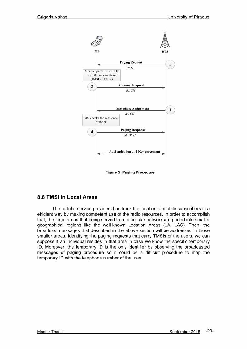
i. The first process is that the BTS performs a paging request trying to locate the destination mobile station. The BTS forwards a broadcast paging request message addressing the whole Location Area (specific VLR) that has seen the MS lastly. This paging request message is transmitted via the downlink PCH channel. That broadcast message is transmitted via the PCCH channel carrying the subscriber’s TMSI or IMSI. A PCCH can be of type 1, 2 or 3. Those PCCH messages that request a MS with a specific LAC, can carry 2, 3 or 4 unique identities (TMSI or IMSI) respectively.
Grigoris Valtas University of Piraeus
Master Thesis September 2015 -19-
ii. As the paging request is broadcast message all the MSs that are in the particular LA hear and intercept that message. Each MS receives the paging request message and compares its own identity (either TMSI or IMSI) with the one included in the broadcasted message. In case these two components match the MS sends a channel request message from the BTS. This channel request message includes a random reference number and is transmitted over the uplink RACH requesting channel resources.
iii. The BTS that receives the channel request message via RACH
acknowledges that and starts allocating radio resources by creating a dedicated channel. The details of the dedicated channel are send back to the MS by using an Immediate The immediate assignment message is actual response to the channel request message from the MS. It contains a unique identifier that matches the previous one from the channel request message. Due to the fact the immediate assignment message is both downlink and broadcast, every MS has the ability intercept it and chooses whether that message contains the matching unique identifier or not. The immediate assignment message includes also the random reference number that was included in the respective channel request message of the above step.
iv. The MS upon receiving the immediate assignment message from the BTS,
compares the above random reference included in the immediate assignment message and if the these references match the MS tunes to dedicated signaling channel called SDCCH. In that point the MS established a signaling link over SDCCH sends a paging reply message to the corresponding BTS using the uplink SDCCH. From that time, the BTS and the MS negotiate security measures (authentication, ciphering) and setup, authentication procedures. After the negotiation step, a traffic channel is established over the a-interface and data (voice or text) is being transmitted.
GSM specifications include different types of paging request messages related with the number of MSs (subscribers) that can be paged each time. A paging request may include more than one MS identifiers (IMSI / TMSI). There are three types of paging requests: paging request type 1,2 and 3:
Ø Paging request type 1: Addresses one or two mobile subscribers at once.
Ø Paging request type 2: Addresses two or three mobile subscribers with one request.
Ø Paging request type 3: Addresses four mobile subscribers with one paging
request message.
Grigoris Valtas University of Piraeus
Master Thesis September 2015 -20-
Paging Request
Channel Request
Immediate Assignment
Paging Response
Authentication and Key agreement
MS BTS
PCH
RACH
AGCH
SDDCH
MS compares its identity with the received one
(IMSI or TMSI)
MS checks the reference number
1
2
3
4
Figure 5: Paging Procedure
8.8 TMSI in Local Areas The cellular service providers has track the location of mobile subscribers in a efficient way by making competent use of the radio resources. In order to accomplish that, the large areas that being served from a cellular network are parted into smaller geographical regions like the well-known Location Areas (LA, LAC). Then, the broadcast messages that described in the above section will be addressed in those smaller areas. Identifying the paging requests that carry TMSIs of the users, we can suppose if an individual resides in that area in case we know the specific temporary ID. Moreover, the temporary ID is the only identifier by observing the broadcasted messages of paging procedure so it could be a difficult procedure to map the temporary ID with the telephone number of the user.
Grigoris Valtas University of Piraeus
Master Thesis September 2015 -21-
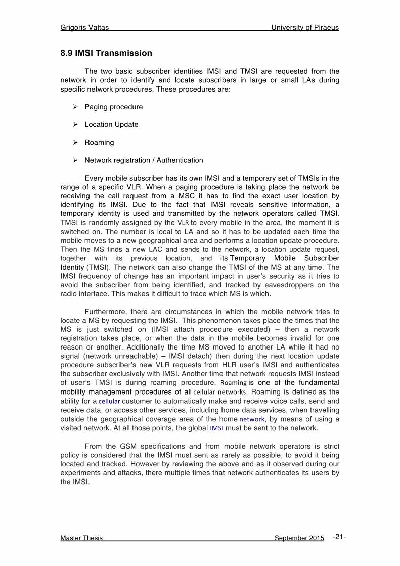
8.9 IMSI Transmission The two basic subscriber identities IMSI and TMSI are requested from the network in order to identify and locate subscribers in large or small LAs during specific network procedures. These procedures are:
Ø Paging procedure
Ø Location Update
Ø Roaming
Ø Network registration / Authentication Every mobile subscriber has its own IMSI and a temporary set of TMSIs in the range of a specific VLR. When a paging procedure is taking place the network be receiving the call request from a MSC it has to find the exact user location by identifying its IMSI. Due to the fact that IMSI reveals sensitive information, a temporary identity is used and transmitted by the network operators called TMSI. TMSI is randomly assigned by the VLR to every mobile in the area, the moment it is switched on. The number is local to LA and so it has to be updated each time the mobile moves to a new geographical area and performs a location update procedure. Then the MS finds a new LAC and sends to the network, a location update request, together with its previous location, and its Temporary Mobile Subscriber Identity (TMSI). The network can also change the TMSI of the MS at any time. The IMSI frequency of change has an important impact in user’s security as it tries to avoid the subscriber from being identified, and tracked by eavesdroppers on the radio interface. This makes it difficult to trace which MS is which. Furthermore, there are circumstances in which the mobile network tries to locate a MS by requesting the IMSI. This phenomenon takes place the times that the MS is just switched on (IMSI attach procedure executed) – then a network registration takes place, or when the data in the mobile becomes invalid for one reason or another. Additionally the time MS moved to another LA while it had no signal (network unreachable) – IMSI detach) then during the next location update procedure subscriber’s new VLR requests from HLR user’s IMSI and authenticates the subscriber exclusively with IMSI. Another time that network requests IMSI instead of user’s TMSI is during roaming procedure. Roaming is one of the fundamental mobility management procedures of all cellular networks. Roaming is defined as the ability for a cellular customer to automatically make and receive voice calls, send and receive data, or access other services, including home data services, when travelling outside the geographical coverage area of the home network, by means of using a visited network. At all those points, the global IMSI must be sent to the network. From the GSM specifications and from mobile network operators is strict policy is considered that the IMSI must sent as rarely as possible, to avoid it being located and tracked. However by reviewing the above and as it observed during our experiments and attacks, there multiple times that network authenticates its users by the IMSI.
Grigoris Valtas University of Piraeus
Master Thesis September 2015 -22-
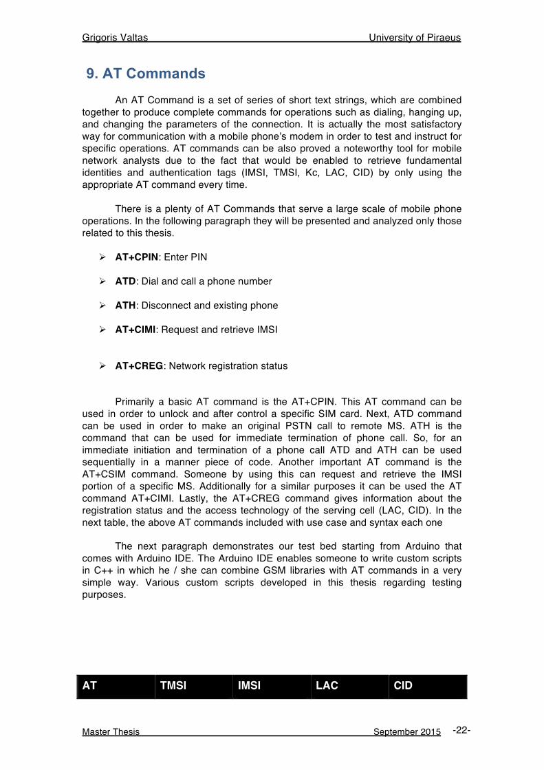
9. AT Commands An AT Command is a set of series of short text strings, which are combined together to produce complete commands for operations such as dialing, hanging up, and changing the parameters of the connection. It is actually the most satisfactory way for communication with a mobile phone’s modem in order to test and instruct for specific operations. AT commands can be also proved a noteworthy tool for mobile network analysts due to the fact that would be enabled to retrieve fundamental identities and authentication tags (IMSI, TMSI, Kc, LAC, CID) by only using the appropriate AT command every time. There is a plenty of AT Commands that serve a large scale of mobile phone operations. In the following paragraph they will be presented and analyzed only those related to this thesis.
Ø AT+CPIN: Enter PIN
Ø ATD: Dial and call a phone number
Ø ATH: Disconnect and existing phone
Ø AT+CIMI: Request and retrieve IMSI
Ø AT+CREG: Network registration status Primarily a basic AT command is the AT+CPIN. This AT command can be used in order to unlock and after control a specific SIM card. Next, ATD command can be used in order to make an original PSTN call to remote MS. ATH is the command that can be used for immediate termination of phone call. So, for an immediate initiation and termination of a phone call ATD and ATH can be used sequentially in a manner piece of code. Another important AT command is the AT+CSIM command. Someone by using this can request and retrieve the IMSI portion of a specific MS. Additionally for a similar purposes it can be used the AT command AT+CIMI. Lastly, the AT+CREG command gives information about the registration status and the access technology of the serving cell (LAC, CID). In the next table, the above AT commands included with use case and syntax each one The next paragraph demonstrates our test bed starting from Arduino that comes with Arduino IDE. The Arduino IDE enables someone to write custom scripts in C++ in which he / she can combine GSM libraries with AT commands in a very simple way. Various custom scripts developed in this thesis regarding testing purposes.
AT TMSI IMSI LAC CID
Grigoris Valtas University of Piraeus
Master Thesis September 2015 -23-
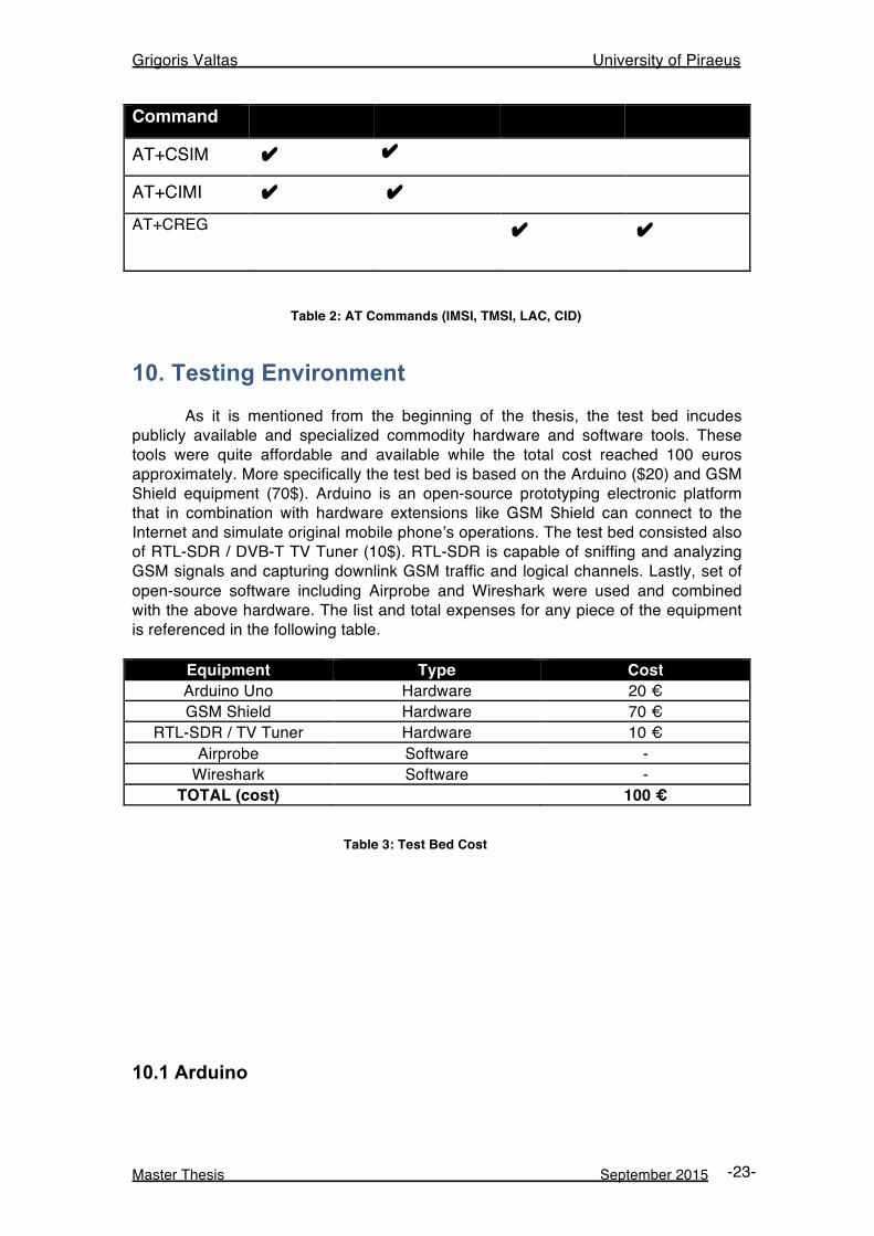
Command
AT+CSIM ✔ ✔
AT+CIMI ✔ ✔
AT+CREG
✔ ✔
Table 2: AT Commands (IMSI, TMSI, LAC, CID)
10. Testing Environment As it is mentioned from the beginning of the thesis, the test bed incudes publicly available and specialized commodity hardware and software tools. These tools were quite affordable and available while the total cost reached 100 euros approximately. More specifically the test bed is based on the Arduino ($20) and GSM Shield equipment (70$). Arduino is an open-source prototyping electronic platform that in combination with hardware extensions like GSM Shield can connect to the Internet and simulate original mobile phone’s operations. The test bed consisted also of RTL-SDR / DVB-T TV Tuner (10$). RTL-SDR is capable of sniffing and analyzing GSM signals and capturing downlink GSM traffic and logical channels. Lastly, set of open-source software including Airprobe and Wireshark were used and combined with the above hardware. The list and total expenses for any piece of the equipment is referenced in the following table.
Equipment Type Cost Arduino Uno Hardware 20 € GSM Shield Hardware 70 €
RTL-SDR / TV Tuner Hardware 10 € Airprobe Software -
Wireshark Software - TOTAL (cost) 100 €
Table 3: Test Bed Cost
10.1 Arduino
Grigoris Valtas University of Piraeus
Master Thesis September 2015 -24-
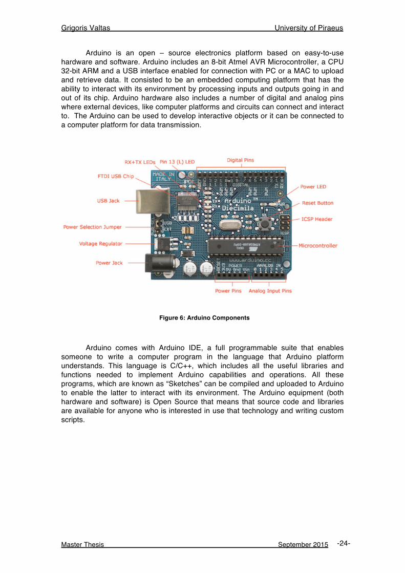
Arduino is an open – source electronics platform based on easy-to-use hardware and software. Arduino includes an 8-bit Atmel AVR Microcontroller, a CPU 32-bit ARM and a USB interface enabled for connection with PC or a MAC to upload and retrieve data. It consisted to be an embedded computing platform that has the ability to interact with its environment by processing inputs and outputs going in and out of its chip. Arduino hardware also includes a number of digital and analog pins where external devices, like computer platforms and circuits can connect and interact to. The Arduino can be used to develop interactive objects or it can be connected to a computer platform for data transmission.
Figure 6: Arduino Components
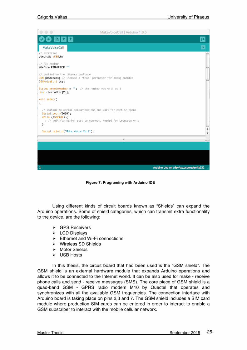
Arduino comes with Arduino IDE, a full programmable suite that enables someone to write a computer program in the language that Arduino platform understands. This language is C/C++, which includes all the useful libraries and functions needed to implement Arduino capabilities and operations. All these programs, which are known as “Sketches” can be compiled and uploaded to Arduino to enable the latter to interact with its environment. The Arduino equipment (both hardware and software) is Open Source that means that source code and libraries are available for anyone who is interested in use that technology and writing custom scripts.
Grigoris Valtas University of Piraeus
Master Thesis September 2015 -25-
Figure 7: Programing with Arduino IDE
Using different kinds of circuit boards known as “Shields” can expand the Arduino operations. Some of shield categories, which can transmit extra functionality to the device, are the following:
Ø GPS Receivers Ø LCD Displays Ø Ethernet and Wi-Fi connections Ø Wireless SD Shields Ø Motor Shields Ø USB Hosts
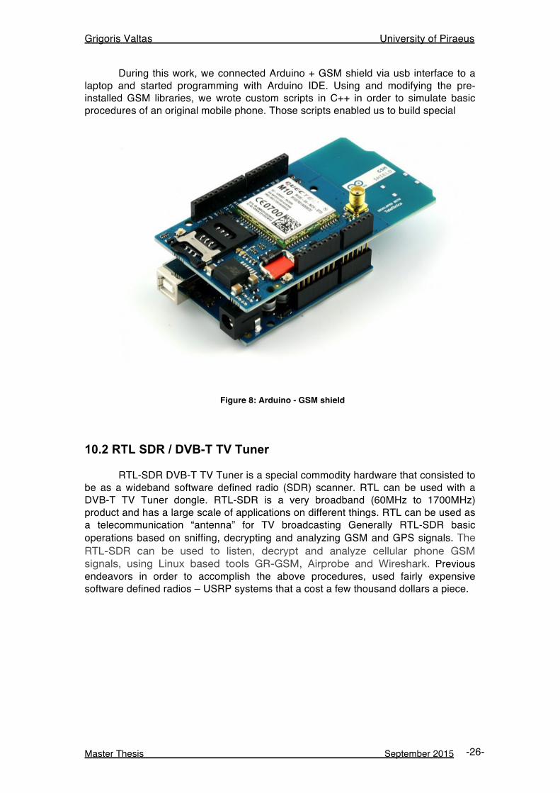
In this thesis, the circuit board that had been used is the “GSM shield”. The GSM shield is an external hardware module that expands Arduino operations and allows it to be connected to the Internet world. It can be also used for make - receive phone calls and send - receive messages (SMS). The core piece of GSM shield is a quad-band GSM - GPRS radio modem M10 by Quectel that operates and synchronizes with all the available GSM frequencies. The connection interface with Arduino board is taking place on pins 2,3 and 7. The GSM shield includes a SIM card module where production SIM cards can be entered in order to interact to enable a GSM subscriber to interact with the mobile cellular network.
Grigoris Valtas University of Piraeus
Master Thesis September 2015 -26-
During this work, we connected Arduino + GSM shield via usb interface to a laptop and started programming with Arduino IDE. Using and modifying the pre- installed GSM libraries, we wrote custom scripts in C++ in order to simulate basic procedures of an original mobile phone. Those scripts enabled us to build special
Figure 8: Arduino - GSM shield
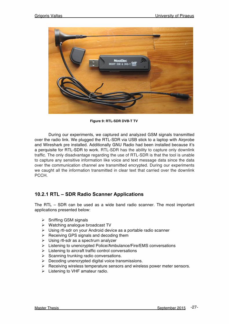
10.2 RTL SDR / DVB-T TV Tuner RTL-SDR DVB-T TV Tuner is a special commodity hardware that consisted to be as a wideband software defined radio (SDR) scanner. RTL can be used with a DVB-T TV Tuner dongle. RTL-SDR is a very broadband (60MHz to 1700MHz) product and has a large scale of applications on different things. RTL can be used as a telecommunication “antenna” for TV broadcasting Generally RTL-SDR basic operations based on sniffing, decrypting and analyzing GSM and GPS signals. The RTL-SDR can be used to listen, decrypt and analyze cellular phone GSM signals, using Linux based tools GR-GSM, Airprobe and Wireshark. Previous endeavors in order to accomplish the above procedures, used fairly expensive software defined radios – USRP systems that a cost a few thousand dollars a piece.
Grigoris Valtas University of Piraeus
Master Thesis September 2015 -27-
Figure 9: RTL-SDR DVB-T TV
During our experiments, we captured and analyzed GSM signals transmitted over the radio link. We plugged the RTL-SDR via USB stick to a laptop with Airprobe and Wireshark pre installed. Additionally GNU Radio had been installed because it’s a perquisite for RTL-SDR to work. RTL-SDR has the ability to capture only downlink traffic. The only disadvantage regarding the use of RTL-SDR is that the tool is unable to capture any sensitive information like voice and text message data since the data over the communication channel are transmitted encrypted. During our experiments we caught all the information transmitted in clear text that carried over the downlink PCCH.
10.2.1 RTL – SDR Radio Scanner Applications The RTL – SDR can be used as a wide band radio scanner. The most important applications presented below:
Ø Sniffing GSM signals Ø Watching analogue broadcast TV Ø Using rtl-sdr on your Android device as a portable radio scanner Ø Receiving GPS signals and decoding them Ø Using rtl-sdr as a spectrum analyzer Ø Listening to unencrypted Police/Ambulance/Fire/EMS conversations Ø Listening to aircraft traffic control conversations Ø Scanning trunking radio conversations. Ø Decoding unencrypted digital voice transmissions. Ø Receiving wireless temperature sensors and wireless power meter sensors. Ø Listening to VHF amateur radio.
Grigoris Valtas University of Piraeus
Master Thesis September 2015 -28-
10.2.2 Software Defined Radio (SDR) Radio components such as modulators, demodulators and amplifiers are traditionally implemented in hardware components. The advent of modern computing allows most of these traditionally hardware based components to be implemented into software instead. Hence, the software defined radio. This enables easy signal processing and thus cheap wide band scanner radios to be produced. A basic SDR system may consist of a personal computer equipped with a sound card, or other analog-to-digital converter, preceded by some form of RF front end. Significant amounts of signal processing are handed over to the general-purpose processor, rather than being done in special-purpose hardware (electronic circuits). Such a design produces a radio, which can receive and transmit widely different radio protocols (sometimes referred to as waveforms) based solely on the software used. Software radios have significant utility for the military and cell phone services, both of which must serve a wide variety of changing radio protocols in real time.
10.3 Open-source software tools The test bed also includes various open source and free software tools including:
Ø Airprobe: Protocol parsing and decoding
Ø Wireshark: Packet sniffing and analysis
Ø Kalibrate: Scanner for GSM BTS in a given frequency band.
It is important to mention that all the above tools are available in the Linux operating system.
10.3.1 Airprobe Airprobe is an open-source project trying to build an air-interface analysis tool for the GSM (and possible later 3G) mobile phone standard. This project came forth out of the GSM-sniffer project. When you currently clone the git repository, you will get nearly ten projects. Some of these serve as libraries for the other projects (e.g. gsmstack), some of these have more or less the same function (e.g. gsm-receiver). The most interesting part of AirProbe is the gsm-receiver project. It is, at this moment, the best working capture tool for GSM. It comes with two simple shell scripts that call all the necessary functions for saving the signals on a frequency to a file and for interpreting the signals in this file. Calling capture.sh [duration==10] [decim==112] [gain==52] with a frequency will capture the signals on that frequency
Grigoris Valtas University of Piraeus
Master Thesis September 2015 -29-
to a file. The duration, decimation and gain are optional arguments with default values. A file will be created called capture. cfile, containing the captured IQ samples. These can then be interpreted by calling: go.sh [decim==112] The file name has to be provided, but the decimation is again optional, though you should use the same decimation value that was used during capturing. The go.sh script runs a python file. and does all the processing, needed to get the information bits out of the samples. This results in a series of hex values that represent the information as sent by the GSM network. The go.sh script uses a UNIX pipe method to have these hex-codes interpreted by gsmdecode - one of the other projects in the AirProbe repository. You could also try to convert these hex codes to a pcap file, which can be read by the Wireshark program. Currently the gsm-receiver project will only decode the downlink (GSM network to mobile phone). Standard it will look at the first time slot of a frequency), though this can be changed in the python code. At this moment it can handle several of the control channels in GSM and speech channels. However, due to encryption and frequency hopping this will not yet work in most real world situations.
11 RTL-SDR DVB-T TV Installation In this section we demonstrate step-by-step a proper installation and configuration of the RTL-SDR software. Following that, we also present a simple procedure of sniffing and analyzing the GSM traffic. The installation took place to virtual machine with a Kali Linux distribution pre installed. For proper virtualization and correct interconnectivity we used VMware solution due to the fact that Virtual Box is reported not to work well with the RTL-SDR, as its USB bandwidth capabilities are considered poor. It is also proven that some Linux distributions may not be able to get Airprobe working so Kali Linux is considered to be identical for those experiments. Having installed a Kali Linux distribution just logged in and opens a terminal.
11.1 Kalibrate - RTL Beginning with the RTL-SDR we have to install the Kalibrate utility. Kalibrate is a useful tool that enables us to identify the available principal GSM channels in our area. Kalibrate-RTL or kal is a Linux program used to scan for GSM BTSs in a given frequency band and can use those BTSs to determine the frequency offset error of our RTL-SDR dongle. Every RTL-SDR dongle has a small frequency error as it is cheaply mass-produced and not tested for accuracy. The source code of Kalibrate can find by following the link below: Download Kalibrate Source Code https://github.com/steve-m/kalibrate-rtl
Grigoris Valtas University of Piraeus
Master Thesis September 2015 -30-
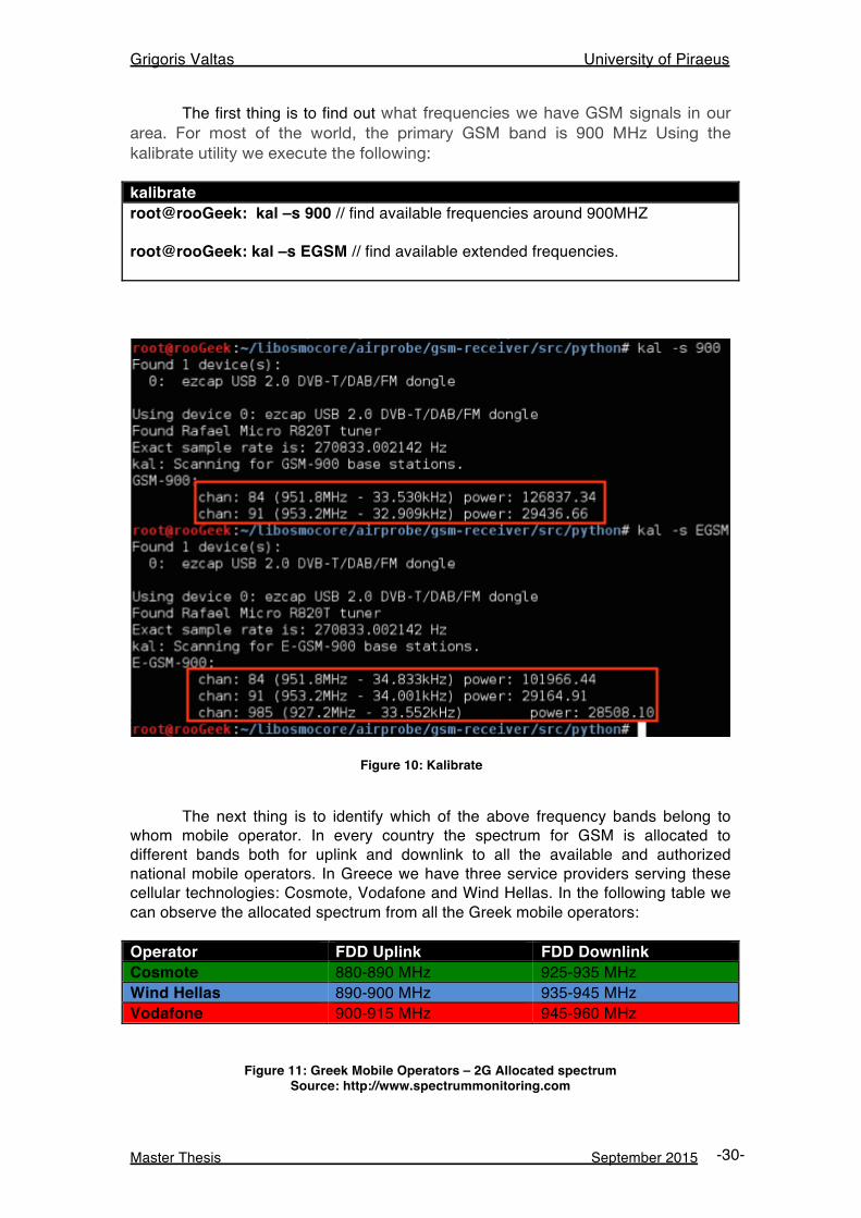
The first thing is to find out what frequencies we have GSM signals in our area. For most of the world, the primary GSM band is 900 MHz Using the kalibrate utility we execute the following: kalibrate root@rooGeek: kal –s 900 // find available frequencies around 900MHZ root@rooGeek: kal –s EGSM // find available extended frequencies.
Figure 10: Kalibrate
The next thing is to identify which of the above frequency bands belong to whom mobile operator. In every country the spectrum for GSM is allocated to different bands both for uplink and downlink to all the available and authorized national mobile operators. In Greece we have three service providers serving these cellular technologies: Cosmote, Vodafone and Wind Hellas. In the following table we can observe the allocated spectrum from all the Greek mobile operators: Operator FDD Uplink FDD Downlink Cosmote 880-890 MHz 925-935 MHz Wind Hellas 890-900 MHz 935-945 MHz Vodafone 900-915 MHz 945-960 MHz
Figure 11: Greek Mobile Operators – 2G Allocated spectrum
Source: http://www.spectrummonitoring.com
Grigoris Valtas University of Piraeus
Master Thesis September 2015 -31-
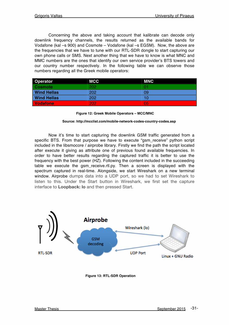
Concerning the above and taking account that kalibrate can decode only downlink frequency channels, the results returned as the available bands for Vodafone (kal –s 900) and Cosmote – Vodafone (kal –s EGSM). Now, the above are the frequencies that we have to tune with our RTL-SDR dongle to start capturing our own phone calls or SMS. Next another thing that we have to know is what MNC and MMC numbers are the ones that identify our own service provider’s BTS towers and our country number respectively. In the following table we can observe those numbers regarding all the Greek mobile operators: Operator MCC MNC Cosmote 202 01 Wind Hellas 202 09 Wind Hellas 202 10 Vodafone 202 05 Figure 12: Greek Mobile Operators – MCC/MNC
Source: http://mcclist.com/mobile-network-codes-country-codes.asp
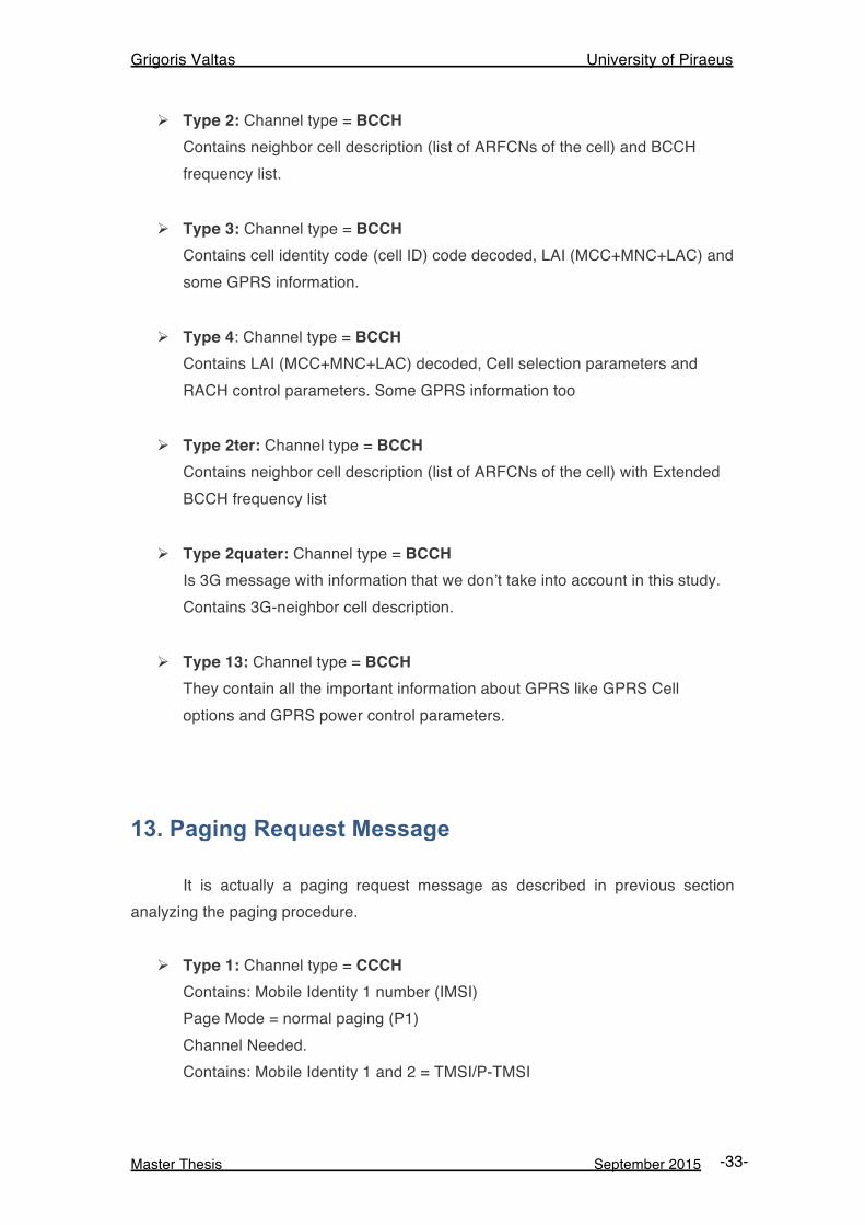
Now it’s time to start capturing the downlink GSM traffic generated from a specific BTS. From that purpose we have to execute “gsm_receive” python script included in the libsmocore / airprobe library. Firstly we find the path the script located after execute it giving as attribute one of previous found available frequencies. In order to have better results regarding the captured traffic it is better to use the frequency with the best power (HZ). Following the content included in the succeeding table we execute the gsm_receive.rtl.py. Then a screen is displayed with the spectrum captured in real-time. Alongside, we start Wireshark on a new terminal window. Airprobe dumps data into a UDP port, so we had to set Wireshark to listen to this. Under the Start button in Wireshark, we first set the capture interface to Loopback: lo and then pressed Start.
Figure 13: RTL-SDR Operation
Grigoris Valtas University of Piraeus
Master Thesis September 2015 -32-
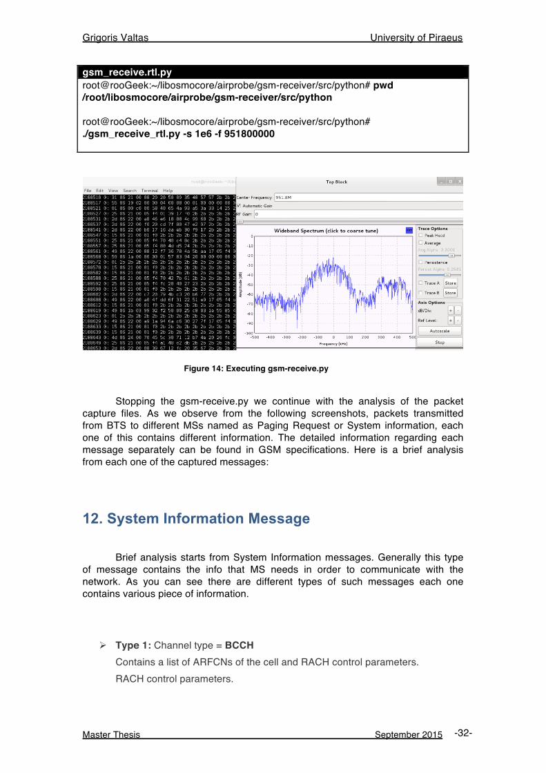
gsm_receive.rtl.py root@rooGeek:~/libosmocore/airprobe/gsm-receiver/src/python# pwd /root/libosmocore/airprobe/gsm-receiver/src/python root@rooGeek:~/libosmocore/airprobe/gsm-receiver/src/python# ./gsm_receive_rtl.py -s 1e6 -f 951800000
Figure 14: Executing gsm-receive.py
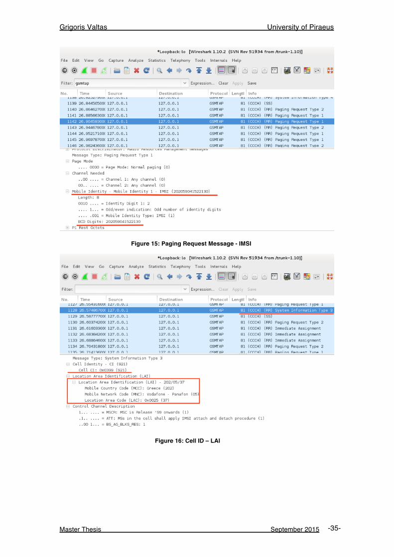
Stopping the gsm-receive.py we continue with the analysis of the packet capture files. As we observe from the following screenshots, packets transmitted from BTS to different MSs named as Paging Request or System information, each one of this contains different information. The detailed information regarding each message separately can be found in GSM specifications. Here is a brief analysis from each one of the captured messages:
12. System Information Message Brief analysis starts from System Information messages. Generally this type of message contains the info that MS needs in order to communicate with the network. As you can see there are different types of such messages each one contains various piece of information.
Ø Type 1: Channel type = BCCH Contains a list of ARFCNs of the cell and RACH control parameters. RACH control parameters.
Grigoris Valtas University of Piraeus
Master Thesis September 2015 -33-
Ø Type 2: Channel type = BCCH Contains neighbor cell description (list of ARFCNs of the cell) and BCCH frequency list.
Ø Type 3: Channel type = BCCH Contains cell identity code (cell ID) code decoded, LAI (MCC+MNC+LAC) and some GPRS information.
Ø Type 4: Channel type = BCCH Contains LAI (MCC+MNC+LAC) decoded, Cell selection parameters and RACH control parameters. Some GPRS information too
Ø Type 2ter: Channel type = BCCH Contains neighbor cell description (list of ARFCNs of the cell) with Extended BCCH frequency list
Ø Type 2quater: Channel type = BCCH Is 3G message with information that we don’t take into account in this study. Contains 3G-neighbor cell description.
Ø Type 13: Channel type = BCCH They contain all the important information about GPRS like GPRS Cell options and GPRS power control parameters.
13. Paging Request Message It is actually a paging request message as described in previous section analyzing the paging procedure.
Ø Type 1: Channel type = CCCH Contains: Mobile Identity 1 number (IMSI) Page Mode = normal paging (P1) Channel Needed. Contains: Mobile Identity 1 and 2 = TMSI/P-TMSI
Grigoris Valtas University of Piraeus
Master Thesis September 2015 -34-
Page Mode = normal paging (0) Channel Needed
Ø Type 2: Channel type = CCCH Contains: Mobile Identity 1, 2 = TMSI/P-TMSI or IMSI Mobile Identity 3 Page Mode = normal paging (0) Channel Needed
Ø Type 3: Channel type = CCCH Contains: Mobile Identity 1, 2, 3 and 4 = TMSI/P-TMSI (Not decoded) Page Mode = normal paging (0) Channel Needed
14. Immediate Assignment Message It is actually an immediate assignment message as described in previous section analyzing the paging procedure.
Ø Channel type = CCCH Contains: Time Advance Value Packet Channel Description (Time Slot) Page Mode = Extended Paging (1)
Grigoris Valtas University of Piraeus
Master Thesis September 2015 -35-
Figure 15: Paging Request Message - IMSI
Figure 16: Cell ID – LAI
Grigoris Valtas University of Piraeus
Master Thesis September 2015 -36-
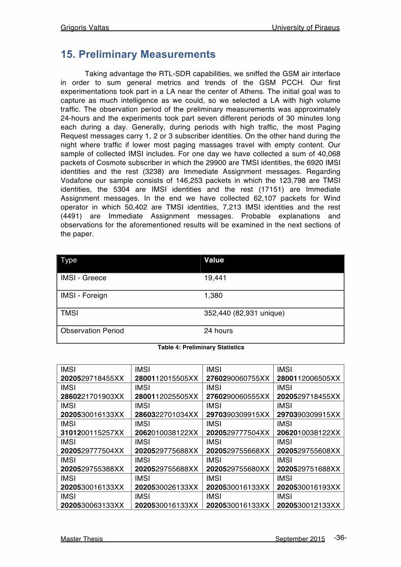
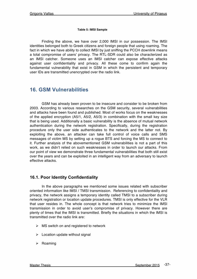
15. Preliminary Measurements Taking advantage the RTL-SDR capabilities, we sniffed the GSM air interface in order to sum general metrics and trends of the GSM PCCH. Our first experimentations took part in a LA near the center of Athens. The initial goal was to capture as much intelligence as we could, so we selected a LA with high volume traffic. The observation period of the preliminary measurements was approximately 24-hours and the experiments took part seven different periods of 30 minutes long each during a day. Generally, during periods with high traffic, the most Paging Request messages carry 1, 2 or 3 subscriber identities. On the other hand during the night where traffic if lower most paging massages travel with empty content. Our sample of collected IMSI includes. For one day we have collected a sum of 40,068 packets of Cosmote subscriber in which the 29900 are TMSI identities, the 6920 IMSI identities and the rest (3238) are Immediate Assignment messages. Regarding Vodafone our sample consists of 146,253 packets in which the 123,798 are TMSI identities, the 5304 are IMSI identities and the rest (17151) are Immediate Assignment messages. In the end we have collected 62,107 packets for Wind operator in which 50,402 are TMSI identities, 7,213 IMSI identities and the rest (4491) are Immediate Assignment messages. Probable explanations and observations for the aforementioned results will be examined in the next sections of the paper. Type Value
IMSI - Greece 19,441
IMSI - Foreign 1,380
TMSI 352,440 (82,931 unique)
Observation Period 24 hours
Table 4: Preliminary Statistics
IMSI 2020529718455XX
IMSI 2800112015505XX
IMSI 2760290060755XX
IMSI 2800112006505XX
IMSI 2860221701903XX
IMSI 2800112025505XX
IMSI 2760290060555XX
IMSI 2020529718455XX
IMSI 2020530016133XX
IMSI 2860322701034XX
IMSI 2970390309915XX
IMSI 2970390309915XX
IMSI 3101200115257XX
IMSI 2062010038122XX
IMSI 2020529777504XX
IMSI 2062010038122XX
IMSI 2020529777504XX
IMSI 2020529775688XX
IMSI 2020529755668XX
IMSI 2020529755608XX
IMSI 2020529755388XX
IMSI 2020529755688XX
IMSI 2020529755680XX
IMSI 2020529751688XX
IMSI 2020530016133XX
IMSI 2020530026133XX
IMSI 2020530016133XX
IMSI 2020530016193XX
IMSI 2020530063133XX
IMSI 2020530016133XX
IMSI 2020530016133XX
IMSI 2020530012133XX
Grigoris Valtas University of Piraeus
Master Thesis September 2015 -37-
Table 5: IMSI Sample
Finding the above, we have over 2,000 IMSI in our possession. The IMSI identities belonged both to Greek citizens and foreign people that using roaming. The fact in which we have ability to collect IMSI by just sniffing the PCCH downlink means a total compromise of users’ privacy. The RTL-SDR could also be characterized as an IMSI catcher. Someone uses an IMSI catcher can expose effective attacks against user confidentiality and privacy. All these come to confirm again the fundamental vulnerability that exist in GSM in which the persistent and temporary user IDs are transmitted unencrypted over the radio link.
16. GSM Vulnerabilities GSM has already been proven to be insecure and consider to be broken from 2003. According to various researches on the GSM security, several vulnerabilities and attacks have been found and published. Most of works focus on the weaknesses of the applied encryption (A5/1, A5/2, A5/3) in combination with the small key size that is being used. Additionally a basic vulnerability is the absence of mutual network authentication during the network registration. Specifically, during the registration procedure only the user side authenticates to the network and the latter not. By exploiting the above, an attacker can take full control of voice calls and SMS messages of victim MS by setting up a rogue BTS and forcing the MS to connect to it. Further analysis of the abovementioned GSM vulnerabilities is not a part of this work, as we didn’t relied on such weaknesses in order to launch our attacks. From our point of view we demonstrate three fundamental vulnerabilities that both still exist over the years and can be exploited in an intelligent way from an adversary to launch effective attacks.
16.1. Poor Identity Confidentiality In the above paragraphs we mentioned some issues related with subscriber oriented information like IMSI / TMSI transmission. Referencing to confidentiality and privacy, the network assigns a temporary identity called TMSI to a subscriber during network registration or location update procedures. TMSI is only effective for the VLR that user resides in. The whole concept is that network tries to minimize the IMSI transmission in order to avoid user’s compromise of privacy. However there are plenty of times that the IMSI is transmitted. Briefly the situations in which the IMSI is transmitted over the radio link are:
Ø MS switch on and registered to network
Ø Location update without signal
Ø Roaming
Grigoris Valtas University of Piraeus
Master Thesis September 2015 -38-
All of the above circumstances could be characterized as the main target in which an adversary can passively sniff the traffic exchanged over the air in order to collect as much IMSI he / she cans in order after launch a probable attack against users. In the first situation an adversary could have put various packets sniffers (RTL-SDR) as well as IMSI catchers in order to collect the identities of users whom MSs are switched on over the day. In the second one an adversary can put its malicious equipment in areas where plenty of people perform location update after a route without network signal. These areas could be identically entrances of Metro stations. Having a set of specialized equipment nearby those areas, a malicious factor would be able to intercept the IMSIs of people. Finally the point of all the above is that network operators should minimize more the situations where the IMSI transmitted.
16.2. Unencrypted Signaling & Control Traffic The second exposed and fundamental vulnerability that we based on and launched our attacks that presented below, all the signaling and control traffic that transmitted between the BTSs of a LA towards the MSs the reside in that LA is unencrypted. As it is mentioned in above paragraph during a paging procedure the network locates the MS by broadcast BCCH. Those messages carry subscriber oriented information like TMSI / IMSI and due to are transmitted in clear text could reveal sensitive information and can be characterized as exploitable from any adversary who passively sniffers the Um interface of the network. During our first experiments above by only setting the RTL-SDR and started sniffing in particular channels of our national service providers frequencies, the paging request messages (of all types) carrying IMSI and TMSI in clear text. So, an adversary can intercept those identities (especially IMSI) in an easy way and having at his / her possession information that considered to be confidential.
16.3. Poor TMSI Frequency change TMSI goal is to hide subscriber physical identity (IMSI) as well as to defend against traffic analysis. The GSM specifications do not mandate a specific structure for the TMSI other than preventing the use of 0xFFFFFFFF. Thus, the operators feel free to choose the value of TMSI per subscriber since it has relevance only to the VLR. The important here is that are not aware of long-lasting TMSI allocation among the subscribers. During our preliminary tests we observed that from 352,440 TMSI found in paging request messages there were only 82,931 unique TMSI. This may proved as an important vulnerability among the whole operation of the network because a long-lasting TMSI can cause traffic analysis attacks against the users. If an adversary with the suitable equipment is able to locate the user that resides in a LA, then it will be more easy for him /her to track its location for bigger time-space as the frequency of TMSI change is small. That situation enabled us to perform effective attacks (as them described in next paragraphs) because long-lasting TMSI between repetitive PSTN calls can be easier for an adversary to map a user’s phone number with a its temporary ID (TMSI).
Grigoris Valtas University of Piraeus
Master Thesis September 2015 -39-
16.4. Fall back to GPRS/EDGE of UMTS/HSPA (3G, 3.5G) As we mentioned in the first sections of our thesis, the GSM remains the dominant cellular technology and operates as a fallback mechanism to latest in use cellular technologies. The concept is that the most UMTS/HSPA devices are GSM/GPRS/EDGE capable and when the UMTS/HSPA service is not available, they are automatically be configured to downgrade their network capabilities and try to connect to GSM/GPRS/EDGE networks. The above could be characterized as an important vulnerability as allows an attacker to force those MSs to behave as simple GSM devices by using malicious actions (e.g. jammers) and then launch well known attacks existing in GSM.
Grigoris Valtas University of Piraeus
Master Thesis September 2015 -40-
17. A Stealthy denial of service attack to Mobile Station Having discussed all the above it’s time to enter to our practical attacks section. In this paragraph, we demonstrate the first of two attacks targeting the cellular technology after taking advantage the effectiveness of the specialized hardware and software systems presented above. In this scenario we perform a denial of service attack to a specific MS by using the Arduino microcontroller combined with the GSM shield. The effectiveness of such an attack is that the victim MS will be unable to receive and serve legitimate phone calls. The way in which this attack can be accomplished is that we continuously make original PSTN calls towards a target MS by using Arduino scripting capabilities where the latter can simulate phone calls in a repetitive mode. The meaning and the key of this attack is that the victim cannot identify that it is under attack due to the fact that the mobile phone does not actually ring. For that reason this type of denial of service can be characterized absolutely as a “stealthy” attack.
17.1. Examining an original phone call Before explain and analyze the basic steps that followed in order to accomplish the DoS attack, it has separate meaning to understand the sentence: “the target phone does not actually ring”. The time we started making various phone calls using the custom scripts written in Arduino IDE, observed that there a quite small time space by the time we dial a MS and the time the MS rings. Launching a plenty of original calls and after applying different counters and AT commands in order to repeat and after terminate a phone a call we reached to an important conclusion. Finally we wrote a custom script (see the appendix) that confirms the following conclusion.
As you can see from the following screenshot the time sequence of an
original phone call in a cellular network, identified that consists of three separate phases that occur successively.
1. Phone dialing
2. Paging request
3. Phone ringing
More specifically, at the first time period (t0) we dial the phone number of the MS we want to attack. Next, at t1 the network has just started the paging procedure in order to locate the victim MS and transmit our call request. It is exactly the time space in which the BTS transmit the paging request message to the target MS. Keep notice in that whole time space (t0 – t1) the MS does not ring. The important issue here is that from t1 and later and after the successful termination of the paging procedure, the MS is considered to be “busy” and any paging request initiated from other callers will be rejected. By reaching the t2 (after 2.5 seconds) the MS starts to ring. To sum up all the above, the elapsed time between dialing the phone number and the completion of the paging procedure is 3 seconds approximately (t1-t0 = 3 sec). Furthermore, between the paging procedure and phone ringing is on average
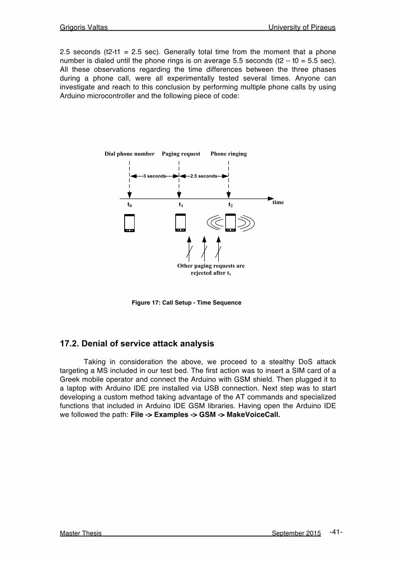
Grigoris Valtas University of Piraeus
Master Thesis September 2015 -41-
2.5 seconds (t2-t1 = 2.5 sec). Generally total time from the moment that a phone number is dialed until the phone rings is on average 5.5 seconds (t2 – t0 = 5.5 sec). All these observations regarding the time differences between the three phases during a phone call, were all experimentally tested several times. Anyone can investigate and reach to this conclusion by performing multiple phone calls by using Arduino microcontroller and the following piece of code:
t0 t1 t2
Phone ringingPaging request
2.5 seconds
Dial phone number
time
Other paging requests are rejected after t1
3 seconds
Figure 17: Call Setup - Time Sequence
17.2. Denial of service attack analysis
Taking in consideration the above, we proceed to a stealthy DoS attack targeting a MS included in our test bed. The first action was to insert a SIM card of a Greek mobile operator and connect the Arduino with GSM shield. Then plugged it to a laptop with Arduino IDE pre installed via USB connection. Next step was to start developing a custom method taking advantage of the AT commands and specialized functions that included in Arduino IDE GSM libraries. Having open the Arduino IDE we followed the path: File -> Examples -> GSM -> MakeVoiceCall.
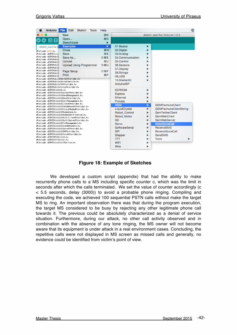
Grigoris Valtas University of Piraeus
Master Thesis September 2015 -42-
Figure 18: Example of Sketches
We developed a custom script (appendix) that had the ability to make recurrently phone calls to a MS including specific counter c, which was the limit in seconds after which the calls terminated. We set the value of counter accordingly (c < 5.5 seconds, delay (3000)) to avoid a probable phone ringing. Compiling and executing the code, we achieved 100 sequential PSTN calls without make the target MS to ring. An important observation there was that during the program execution, the target MS considered to be busy by rejecting any other legitimate phone call towards it. The previous could be absolutely characterized as a denial of service situation. Furthermore, during our attack, no other call activity observed and in combination with the absence of any tone ringing, the MS owner will not become aware that its equipment is under attack in a real environment cases. Concluding, the repetitive calls were not displayed in MS screen as missed calls and generally, no evidence could be identified from victim’s point of view.
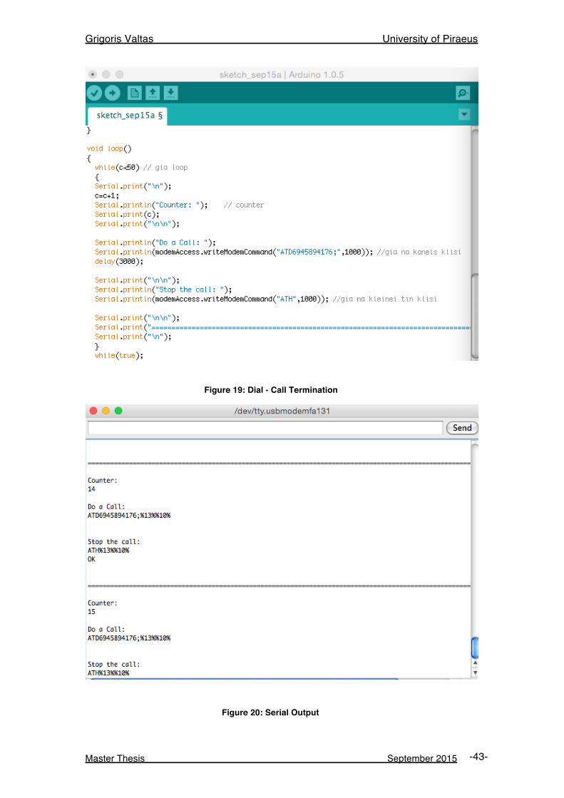
Grigoris Valtas University of Piraeus
Master Thesis September 2015 -43-
Figure 19: Dial - Call Termination
Figure 20: Serial Output
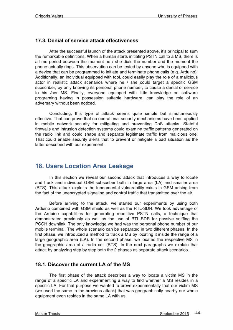
Grigoris Valtas University of Piraeus
Master Thesis September 2015 -44-
17.3. Denial of service attack effectiveness After the successful launch of the attack presented above, it’s principal to sum the remarkable definitions. When a human starts initiating PSTN call to a MS, there is a time period between the moment he / she dials the number and the moment the phone actually rings. This observation can be tested by anyone who is equipped with a device that can be programmed to initiate and terminate phone calls (e.g. Arduino). Additionally, an individual equipped with tool, could easily play the role of a malicious actor in realistic attack scenarios where he / she could target a specific GSM subscriber, by only knowing its personal phone number, to cause a denial of service to his /her MS. Finally, everyone equipped with little knowledge on software programing having in possession suitable hardware, can play the role of an adversary without been noticed. Concluding, this type of attack seems quite simple but simultaneously effective. That can prove that no operational security mechanisms have been applied in mobile network security for mitigating and preventing DoS attacks. Stateful firewalls and intrusion detection systems could examine traffic patterns generated on the radio link and could shape and separate legitimate traffic from malicious one. That could enable security alerts that to prevent or mitigate a bad situation as the latter described with our experiment.
18. Users Location Area Leakage In this section we reveal our second attack that introduces a way to locate and track and individual GSM subscriber both in large area (LA) and smaller area (BTS). This attack exploits the fundamental vulnerability exists in GSM arising from the fact of the unencrypted signaling and control traffic that transmitted over the air. Before arriving to the attack, we started our experiments by using both Arduino combined with GSM shield as well as the RTL-SDR. We took advantage of the Arduino capabilities for generating repetitive PSTN calls, a technique that demonstrated previously as well as the use of RTL-SDR for passive sniffing the PCCH downlink. The only knowledge we had was the personal phone number of our mobile terminal. The whole scenario can be separated in two different phases. In the first phase, we introduced a method to track a MS by locating it inside the range of a large geographic area (LA). In the second phase, we located the respective MS in the geographic area of a radio cell (BTS). In the next paragraphs we explain that attack by analyzing step by step both the 2 phases as separate attack scenarios.
18.1. Discover the current LA of the MS The first phase of the attack describes a way to locate a victim MS in the range of a specific LA and experimenting a way to find whether a MS resides in a specific LA. For that purpose we wanted to prove experimentally that our victim MS (we used the same in the previous attack) that was geographically nearby our whole equipment even resides in the same LA with us.
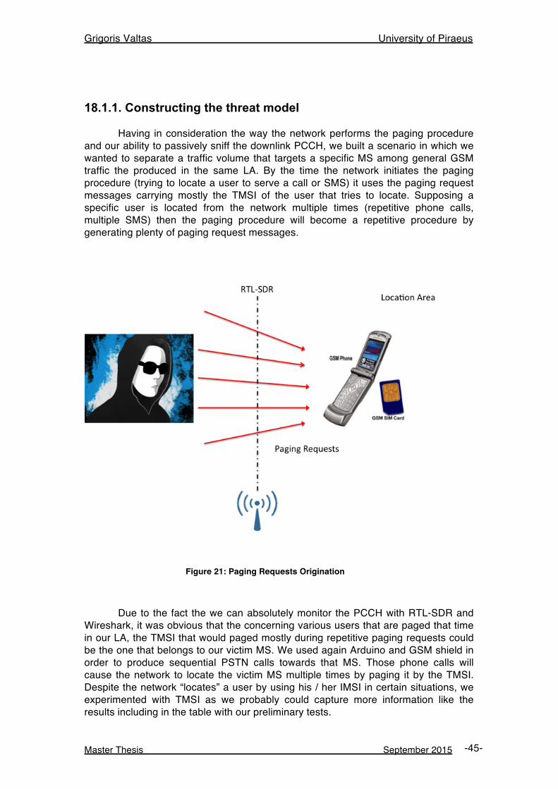
Grigoris Valtas University of Piraeus
Master Thesis September 2015 -45-
18.1.1. Constructing the threat model Having in consideration the way the network performs the paging procedure and our ability to passively sniff the downlink PCCH, we built a scenario in which we wanted to separate a traffic volume that targets a specific MS among general GSM traffic the produced in the same LA. By the time the network initiates the paging procedure (trying to locate a user to serve a call or SMS) it uses the paging request messages carrying mostly the TMSI of the user that tries to locate. Supposing a specific user is located from the network multiple times (repetitive phone calls, multiple SMS) then the paging procedure will become a repetitive procedure by generating plenty of paging request messages.
Figure 21: Paging Requests Origination
Due to the fact the we can absolutely monitor the PCCH with RTL-SDR and Wireshark, it was obvious that the concerning various users that are paged that time in our LA, the TMSI that would paged mostly during repetitive paging requests could be the one that belongs to our victim MS. We used again Arduino and GSM shield in order to produce sequential PSTN calls towards that MS. Those phone calls will cause the network to locate the victim MS multiple times by paging it by the TMSI. Despite the network “locates” a user by using his / her IMSI in certain situations, we experimented with TMSI as we probably could capture more information like the results including in the table with our preliminary tests.
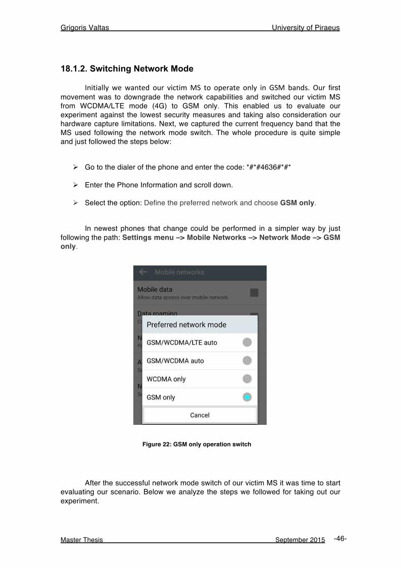
Grigoris Valtas University of Piraeus
Master Thesis September 2015 -46-
18.1.2. Switching Network Mode Initially we wanted our victim MS to operate only in GSM bands. Our first movement was to downgrade the network capabilities and switched our victim MS from WCDMA/LTE mode (4G) to GSM only. This enabled us to evaluate our experiment against the lowest security measures and taking also consideration our hardware capture limitations. Next, we captured the current frequency band that the MS used following the network mode switch. The whole procedure is quite simple and just followed the steps below:
Ø Go to the dialer of the phone and enter the code: *#*#4636#*#*
Ø Enter the Phone Information and scroll down.
Ø Select the option: Define the preferred network and choose GSM only. In newest phones that change could be performed in a simpler way by just following the path: Settings menu –> Mobile Networks –> Network Mode –> GSM only.
Figure 22: GSM only operation switch
After the successful network mode switch of our victim MS it was time to start evaluating our scenario. Below we analyze the steps we followed for taking out our experiment.
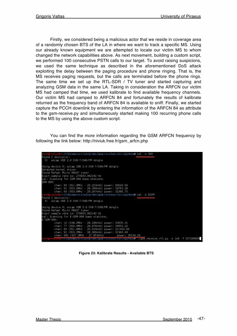
Grigoris Valtas University of Piraeus
Master Thesis September 2015 -47-
Firstly, we considered being a malicious actor that we reside in coverage area of a randomly chosen BTS of the LA in where we want to track a specific MS. Using our already known equipment we are attempted to locate our victim MS to whom changed the network capabilities above. As next movement, building a custom script, we performed 100 consecutive PSTN calls to our target. To avoid raising suspicions, we used the same technique as described in the aforementioned DoS attack exploiting the delay between the paging procedure and phone ringing. That is, the MS receives paging requests, but the calls are terminated before the phone rings. The same time we set up the RTL-SDR / TV tuner and started capturing and analyzing GSM data in the same LA. Taking in consideration the ARFCN our victim MS had camped that time, we used kalibrate to find available frequency channels. Our victim MS had camped to ARFCN 84 and fortunately the results of kalibrate returned as the frequency band of ARFCN 84 is available to sniff. Finally, we started capture the PCCH downlink by entering the information of the ARFCN 84 as attribute to the gsm-receive.py and simultaneously started making 100 recurring phone calls to the MS by using the above custom script.
You can find the more information regarding the GSM ARFCN frequency by following the link below: http://niviuk.free.fr/gsm_arfcn.php
Figure 23: Kalibrate Results - Available BTS
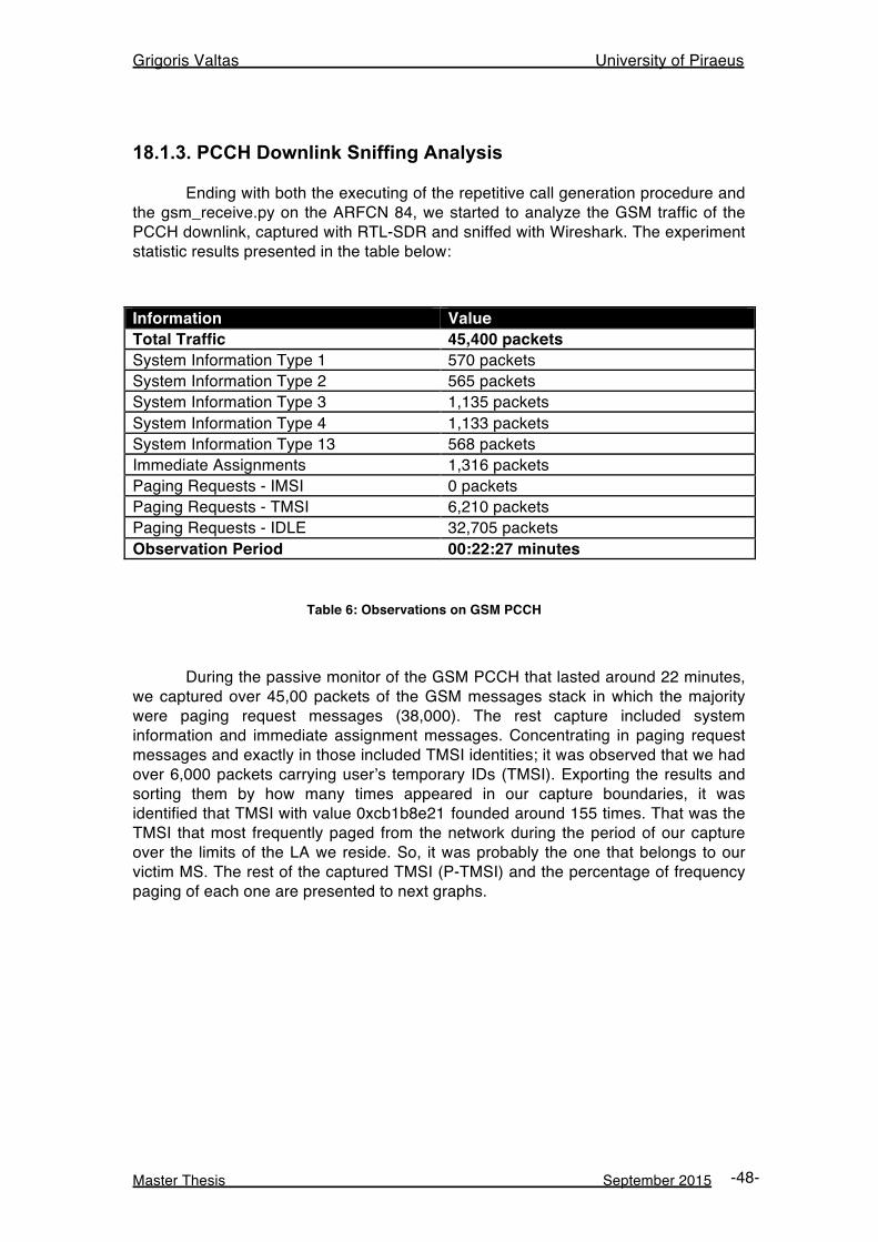
Grigoris Valtas University of Piraeus
Master Thesis September 2015 -48-
18.1.3. PCCH Downlink Sniffing Analysis Ending with both the executing of the repetitive call generation procedure and the gsm_receive.py on the ARFCN 84, we started to analyze the GSM traffic of the PCCH downlink, captured with RTL-SDR and sniffed with Wireshark. The experiment statistic results presented in the table below:
Information Value Total Traffic 45,400 packets System Information Type 1 570 packets System Information Type 2 565 packets System Information Type 3 1,135 packets System Information Type 4 1,133 packets System Information Type 13 568 packets Immediate Assignments 1,316 packets Paging Requests - IMSI 0 packets Paging Requests - TMSI 6,210 packets Paging Requests - IDLE 32,705 packets Observation Period 00:22:27 minutes
Table 6: Observations on GSM PCCH
During the passive monitor of the GSM PCCH that lasted around 22 minutes, we captured over 45,00 packets of the GSM messages stack in which the majority were paging request messages (38,000). The rest capture included system information and immediate assignment messages. Concentrating in paging request messages and exactly in those included TMSI identities; it was observed that we had over 6,000 packets carrying user’s temporary IDs (TMSI). Exporting the results and sorting them by how many times appeared in our capture boundaries, it was identified that TMSI with value 0xcb1b8e21 founded around 155 times. That was the TMSI that most frequently paged from the network during the period of our capture over the limits of the LA we reside. So, it was probably the one that belongs to our victim MS. The rest of the captured TMSI (P-TMSI) and the percentage of frequency paging of each one are presented to next graphs.
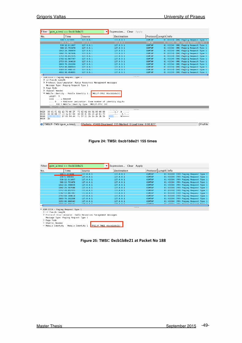
Grigoris Valtas University of Piraeus
Master Thesis September 2015 -49-
Figure 24: TMSI: 0xcb1b8e21 155 times
Figure 25: TMSI: 0xcb1b8e21 at Packet No 188
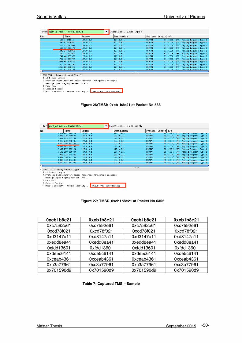
Grigoris Valtas University of Piraeus
Master Thesis September 2015 -50-
Figure 26:TMSI: 0xcb1b8e21 at Packet No 588
Figure 27: TMSI: 0xcb1b8e21 at Packet No 6352
0xcb1b8e21 0xcb1b8e21 0xcb1b8e21 0xcb1b8e21 0xc7592e61 0xc7592e61 0xc7592e61 0xc7592e61 0xcd78f021 0xcd78f021 0xcd78f021 0xcd78f021 0xd3147a11 0xd3147a11 0xd3147a11 0xd3147a11 0xedd8ea41 0xedd8ea41 0xedd8ea41 0xedd8ea41 0xfdd13601 0xfdd13601 0xfdd13601 0xfdd13601 0xde5c6141 0xde5c6141 0xde5c6141 0xde5c6141 0xceab4361 0xceab4361 0xceab4361 0xceab4361 0xc3a77961 0xc3a77961 0xc3a77961 0xc3a77961 0x701590d9 0x701590d9 0x701590d9 0x701590d9
Table 7: Captured TMSI - Sample
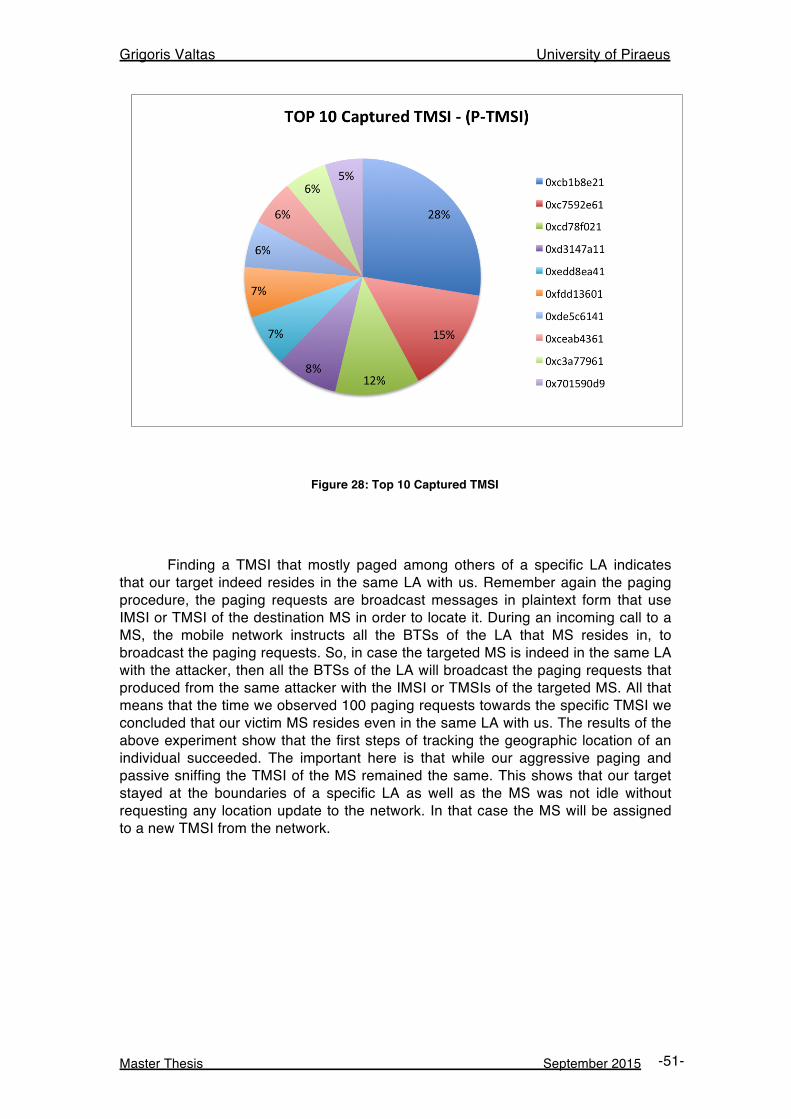
Grigoris Valtas University of Piraeus
Master Thesis September 2015 -51-
Figure 28: Top 10 Captured TMSI
Finding a TMSI that mostly paged among others of a specific LA indicates that our target indeed resides in the same LA with us. Remember again the paging procedure, the paging requests are broadcast messages in plaintext form that use IMSI or TMSI of the destination MS in order to locate it. During an incoming call to a MS, the mobile network instructs all the BTSs of the LA that MS resides in, to broadcast the paging requests. So, in case the targeted MS is indeed in the same LA with the attacker, then all the BTSs of the LA will broadcast the paging requests that produced from the same attacker with the IMSI or TMSIs of the targeted MS. All that means that the time we observed 100 paging requests towards the specific TMSI we concluded that our victim MS resides even in the same LA with us. The results of the above experiment show that the first steps of tracking the geographic location of an individual succeeded. The important here is that while our aggressive paging and passive sniffing the TMSI of the MS remained the same. This shows that our target stayed at the boundaries of a specific LA as well as the MS was not idle without requesting any location update to the network. In that case the MS will be assigned to a new TMSI from the network.
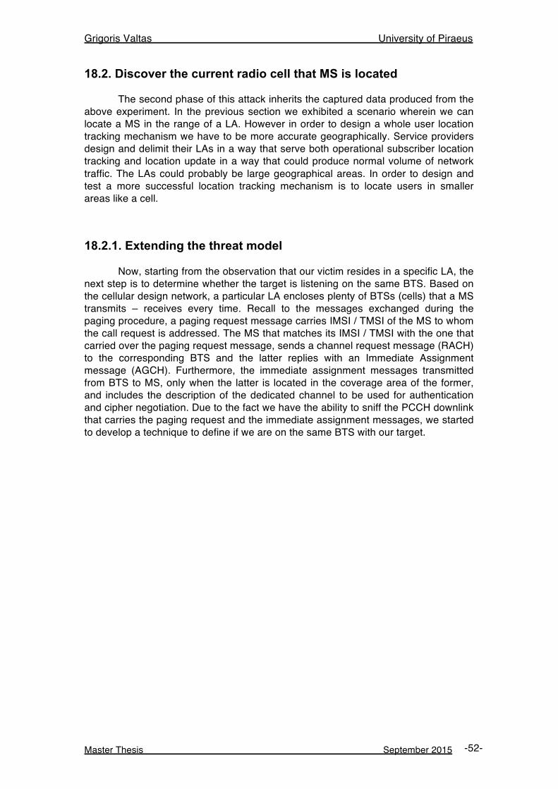
Grigoris Valtas University of Piraeus
Master Thesis September 2015 -52-
18.2. Discover the current radio cell that MS is located
The second phase of this attack inherits the captured data produced from the above experiment. In the previous section we exhibited a scenario wherein we can locate a MS in the range of a LA. However in order to design a whole user location tracking mechanism we have to be more accurate geographically. Service providers design and delimit their LAs in a way that serve both operational subscriber location tracking and location update in a way that could produce normal volume of network traffic. The LAs could probably be large geographical areas. In order to design and test a more successful location tracking mechanism is to locate users in smaller areas like a cell.
18.2.1. Extending the threat model Now, starting from the observation that our victim resides in a specific LA, the next step is to determine whether the target is listening on the same BTS. Based on the cellular design network, a particular LA encloses plenty of BTSs (cells) that a MS transmits – receives every time. Recall to the messages exchanged during the paging procedure, a paging request message carries IMSI / TMSI of the MS to whom the call request is addressed. The MS that matches its IMSI / TMSI with the one that carried over the paging request message, sends a channel request message (RACH) to the corresponding BTS and the latter replies with an Immediate Assignment message (AGCH). Furthermore, the immediate assignment messages transmitted from BTS to MS, only when the latter is located in the coverage area of the former, and includes the description of the dedicated channel to be used for authentication and cipher negotiation. Due to the fact we have the ability to sniff the PCCH downlink that carries the paging request and the immediate assignment messages, we started to develop a technique to define if we are on the same BTS with our target.
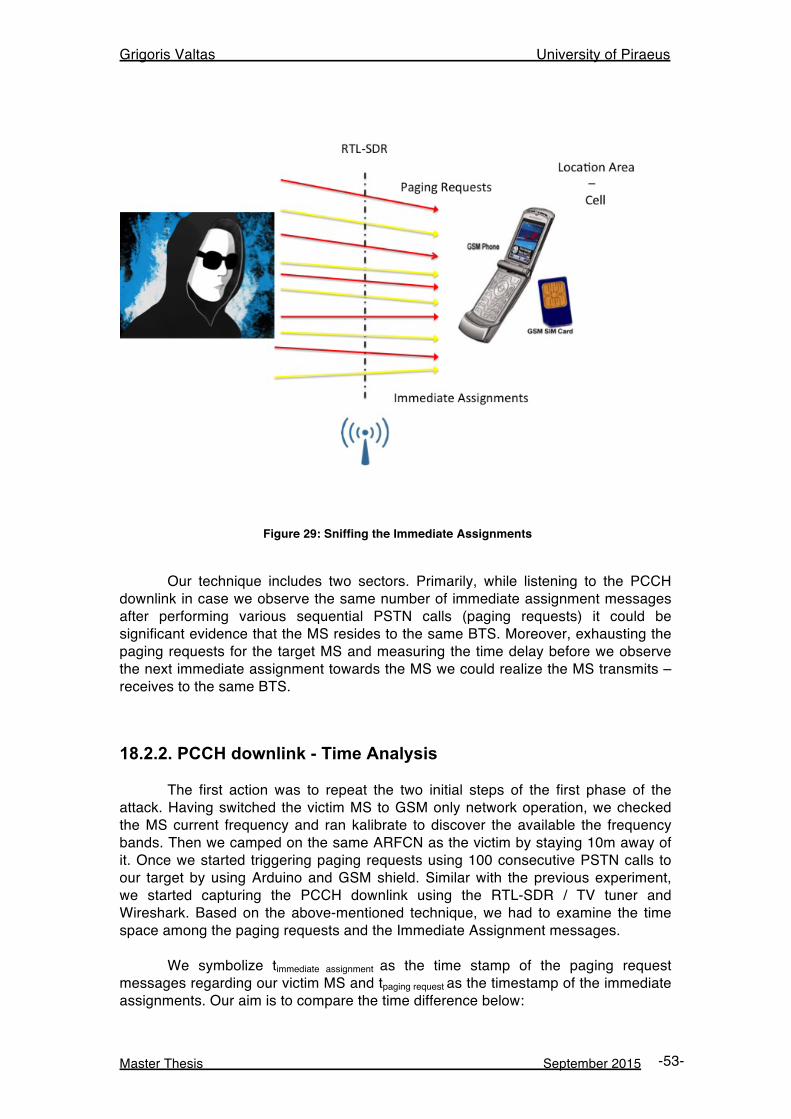
Grigoris Valtas University of Piraeus
Master Thesis September 2015 -53-
Figure 29: Sniffing the Immediate Assignments
Our technique includes two sectors. Primarily, while listening to the PCCH downlink in case we observe the same number of immediate assignment messages after performing various sequential PSTN calls (paging requests) it could be significant evidence that the MS resides to the same BTS. Moreover, exhausting the paging requests for the target MS and measuring the time delay before we observe the next immediate assignment towards the MS we could realize the MS transmits – receives to the same BTS.
18.2.2. PCCH downlink - Time Analysis The first action was to repeat the two initial steps of the first phase of the attack. Having switched the victim MS to GSM only network operation, we checked the MS current frequency and ran kalibrate to discover the available the frequency bands. Then we camped on the same ARFCN as the victim by staying 10m away of it. Once we started triggering paging requests using 100 consecutive PSTN calls to our target by using Arduino and GSM shield. Similar with the previous experiment, we started capturing the PCCH downlink using the RTL-SDR / TV tuner and Wireshark. Based on the above-mentioned technique, we had to examine the time space among the paging requests and the Immediate Assignment messages. We symbolize timmediate assignment as the time stamp of the paging request messages regarding our victim MS and tpaging request as the timestamp of the immediate assignments. Our aim is to compare the time difference below:
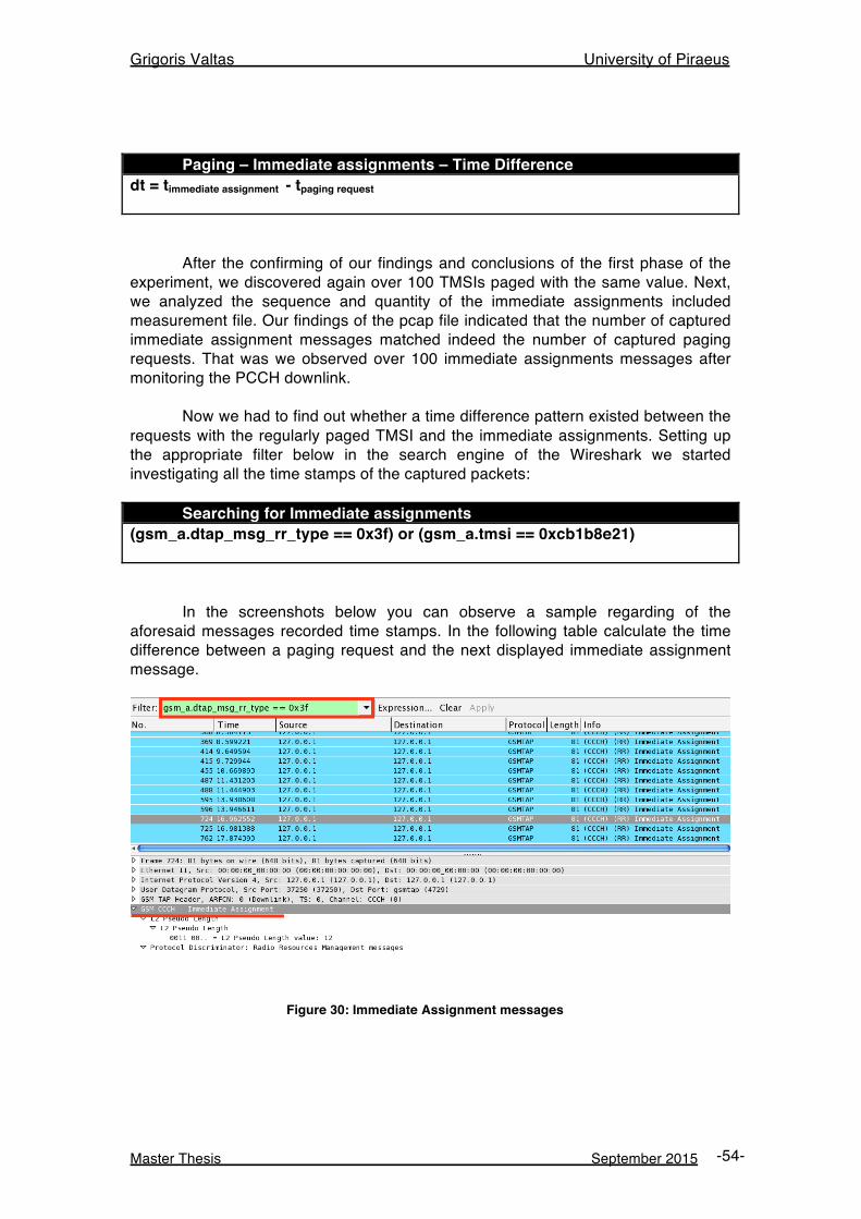
Grigoris Valtas University of Piraeus
Master Thesis September 2015 -54-
Paging – Immediate assignments – Time Difference dt = timmediate assignment - tpaging request After the confirming of our findings and conclusions of the first phase of the experiment, we discovered again over 100 TMSIs paged with the same value. Next, we analyzed the sequence and quantity of the immediate assignments included measurement file. Our findings of the pcap file indicated that the number of captured immediate assignment messages matched indeed the number of captured paging requests. That was we observed over 100 immediate assignments messages after monitoring the PCCH downlink. Now we had to find out whether a time difference pattern existed between the requests with the regularly paged TMSI and the immediate assignments. Setting up the appropriate filter below in the search engine of the Wireshark we started investigating all the time stamps of the captured packets: Searching for Immediate assignments (gsm_a.dtap_msg_rr_type == 0x3f) or (gsm_a.tmsi == 0xcb1b8e21)
In the screenshots below you can observe a sample regarding of the aforesaid messages recorded time stamps. In the following table calculate the time difference between a paging request and the next displayed immediate assignment message.
Figure 30: Immediate Assignment messages
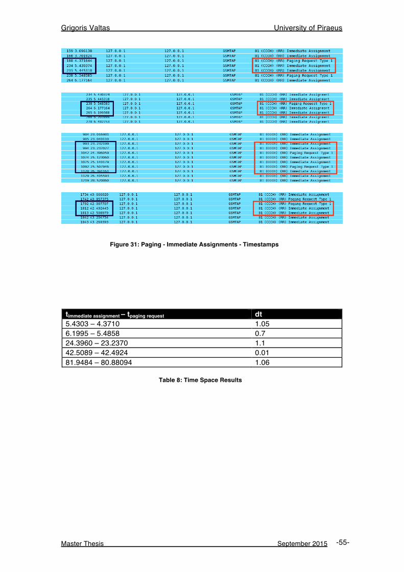
Grigoris Valtas University of Piraeus
Master Thesis September 2015 -55-
Figure 31: Paging - Immediate Assignments - Timestamps
timmediate assignment – tpaging request dt 5.4303 – 4.3710 1.05 6.1995 – 5.4858 0.7 24.3960 – 23.2370 1.1 42.5089 – 42.4924 0.01 81.9484 – 80.88094 1.06
Table 8: Time Space Results
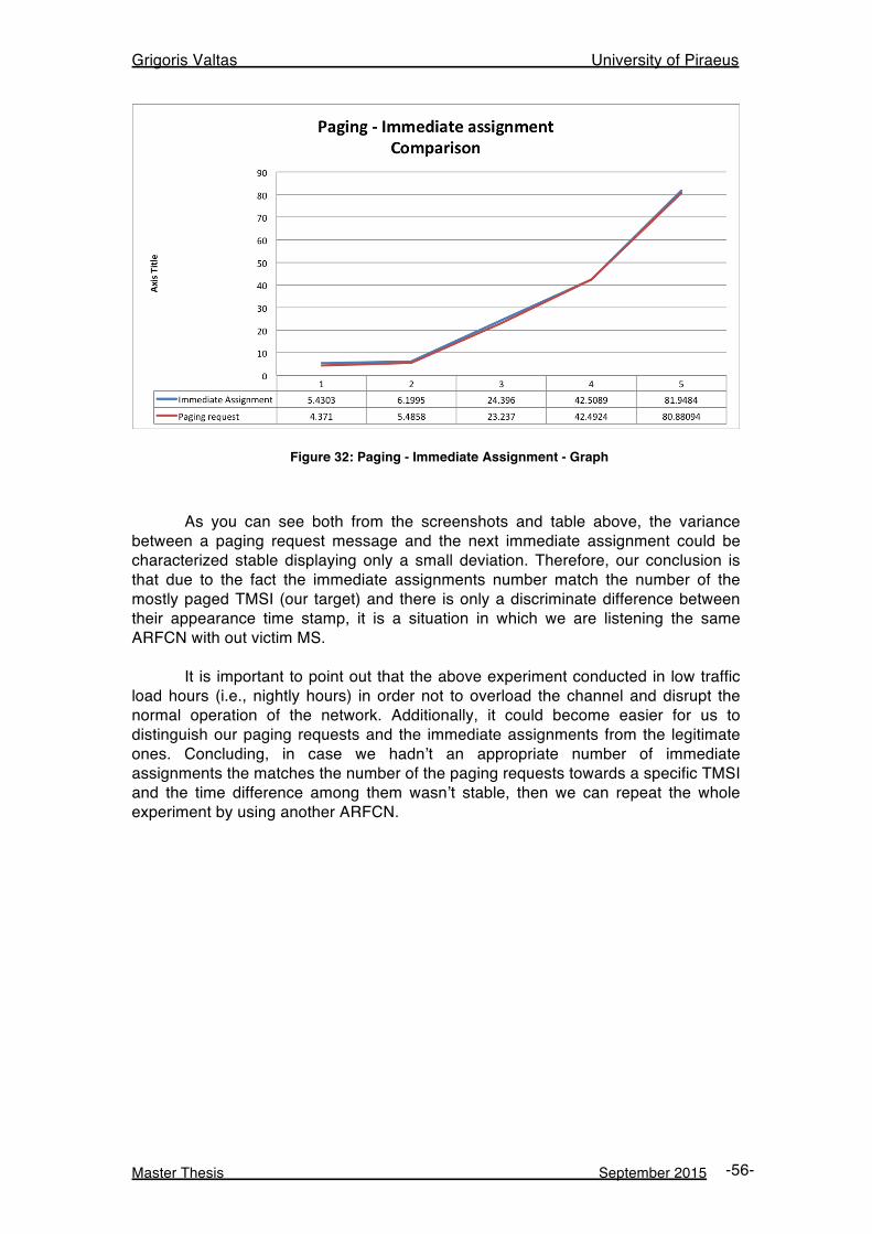
Grigoris Valtas University of Piraeus
Master Thesis September 2015 -56-
Figure 32: Paging - Immediate Assignment - Graph
As you can see both from the screenshots and table above, the variance between a paging request message and the next immediate assignment could be characterized stable displaying only a small deviation. Therefore, our conclusion is that due to the fact the immediate assignments number match the number of the mostly paged TMSI (our target) and there is only a discriminate difference between their appearance time stamp, it is a situation in which we are listening the same ARFCN with out victim MS. It is important to point out that the above experiment conducted in low traffic load hours (i.e., nightly hours) in order not to overload the channel and disrupt the normal operation of the network. Additionally, it could become easier for us to distinguish our paging requests and the immediate assignments from the legitimate ones. Concluding, in case we hadn’t an appropriate number of immediate assignments the matches the number of the paging requests towards a specific TMSI and the time difference among them wasn’t stable, then we can repeat the whole experiment by using another ARFCN.
Grigoris Valtas University of Piraeus
Master Thesis September 2015 -57-
19. Mitigation Techniques Trying to reduce the risk of the vulnerabilities in GSM, it is important now to suggest three basic security measures and techniques in order to prevent such attacks.
19.1. Identities Encryption In GSM networks a proven vulnerability is that user identities are transmitted in clear text over the radio link. Furthermore as it is mentioned before there are some circumstances that the IMSI of a user is exposed over the radio interface. Such situations violate the anonymity of users. Thus, a good solution in order to mitigate threats from any malicious factor could be to implement an improved user identity confidentiality mechanism to make GSM users remain anonymous. That anonymity could be achieved by enforcing symmetric encryption on the user identities.
19.2. Frequent TMSI Change The goal of the TMSI is to hide the a probable compromise of users’ privacy from a malicious actor that can intercept the IMSI by sniffing the PCCH. Network also assigns the TMSI to user / she visits a new VLR (location update) and lasts for a specific time frame. Then changes into another random value. Despite the fact TMSI must changed base on time as it is referenced in GSM specifications, a vulnerable point is that TMSI is long lasting, and that’s our attack against TMSI worked. Thus, the network should decrease the time the TMSI allocated to every user. By making the time that a TMSI is allocated shorter, the TMSI turns to be unrecognizable and the procedure of mapping TMSI to a public phone number becomes more and more difficult.
19.3. Firewalls and Intrusion Detection Systems Firewalls and Intrusion detection systems should be used to mitigate and prevent such attacks from malicious actors. Firewalls that are already implemented in order to block IP traffic on the wireless medium are not trained to accept / block legitimate and malicious GSM signaling traffic. An IDS / IPS solution could be designed and trained in order to examine and separate legitimate signaling traffic from malicious one in case of a denial of service attack occurrence. Following the same technique used from the traditional IDS / IPS systems that are trained to monitor IP traffic, the suggested should be trained to monitor system traffic produced from GSM protocol stack. A network based IDS located in interfaces where signaling traffic produced from could approach the goal of detecting suspicious GSM traffic. Lastly, an IDS / IPS solution for the GSM technology will produces alerts and reports to management stations (BSC – MSC) and help service providers and administrators for better threat manipulation.
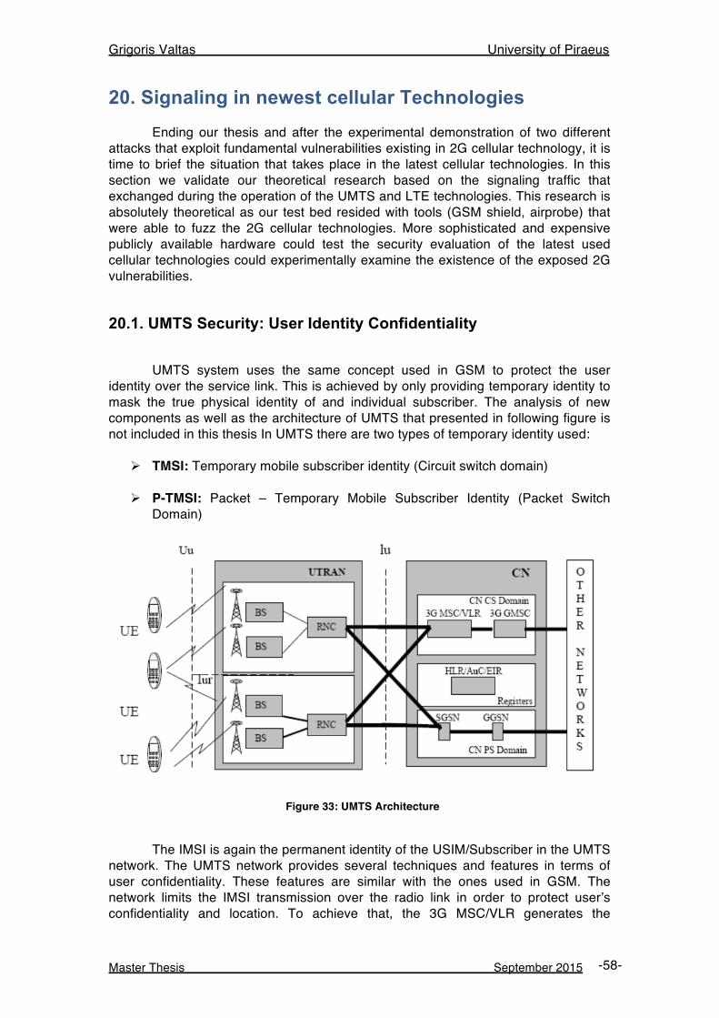
Grigoris Valtas University of Piraeus
Master Thesis September 2015 -58-
20. Signaling in newest cellular Technologies Ending our thesis and after the experimental demonstration of two different attacks that exploit fundamental vulnerabilities existing in 2G cellular technology, it is time to brief the situation that takes place in the latest cellular technologies. In this section we validate our theoretical research based on the signaling traffic that exchanged during the operation of the UMTS and LTE technologies. This research is absolutely theoretical as our test bed resided with tools (GSM shield, airprobe) that were able to fuzz the 2G cellular technologies. More sophisticated and expensive publicly available hardware could test the security evaluation of the latest used cellular technologies could experimentally examine the existence of the exposed 2G vulnerabilities.
20.1. UMTS Security: User Identity Confidentiality UMTS system uses the same concept used in GSM to protect the user identity over the service link. This is achieved by only providing temporary identity to mask the true physical identity of and individual subscriber. The analysis of new components as well as the architecture of UMTS that presented in following figure is not included in this thesis In UMTS there are two types of temporary identity used:
Ø TMSI: Temporary mobile subscriber identity (Circuit switch domain)
Ø P-TMSI: Packet – Temporary Mobile Subscriber Identity (Packet Switch Domain)
Figure 33: UMTS Architecture
The IMSI is again the permanent identity of the USIM/Subscriber in the UMTS network. The UMTS network provides several techniques and features in terms of user confidentiality. These features are similar with the ones used in GSM. The network limits the IMSI transmission over the radio link in order to protect user’s confidentiality and location. To achieve that, the 3G MSC/VLR generates the
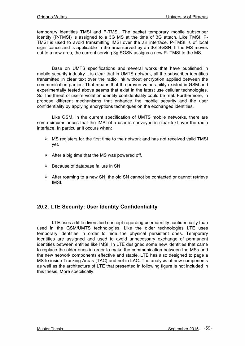
Grigoris Valtas University of Piraeus
Master Thesis September 2015 -59-
temporary identities TMSI and P-TMSI. The packet temporary mobile subscriber identity (P-TMSI) is assigned to a 3G MS at the time of 3G attach. Like TMSI, P-TMSI is used to avoid transmitting IMSI over the air interface. P-TMSI is of local significance and is applicable in the area served by an 3G SGSN. If the MS moves out to a new area, the current serving 3g SGSN assigns a new P- TMSI to the MS. Base on UMTS specifications and several works that have published in mobile security industry it is clear that in UMTS network, all the subscriber identities transmitted in clear text over the radio link without encryption applied between the communication parties. That means that the proven vulnerability existed in GSM and experimentally tested above seems that exist in the latest use cellular technologies. So, the threat of user’s violation identity confidentiality could be real. Furthermore, in propose different mechanisms that enhance the mobile security and the user confidentiality by applying encryptions techniques on the exchanged identities. Like GSM, in the current specification of UMTS mobile networks, there are some circumstances that the IMSI of a user is conveyed in clear-text over the radio interface. In particular it occurs when:
Ø MS registers for the first time to the network and has not received valid TMSI yet.
Ø After a big time that the MS was powered off.
Ø Because of database failure in SN
Ø After roaming to a new SN, the old SN cannot be contacted or cannot retrieve
IMSI.
20.2. LTE Security: User Identity Confidentiality LTE uses a little diversified concept regarding user identity confidentiality than used in the GSM/UMTS technologies. Like the older technologies LTE uses temporary identities in order to hide the physical persistent ones. Temporary identities are assigned and used to avoid unnecessary exchange of permanent identities between entities like IMSI. In LTE designed some new identities that came to replace the older ones in order to make the communication between the MSs and the new network components effective and stable. LTE has also designed to page a MS to inside Tracking Areas (TAC) and not in LAC. The analysis of new components as well as the architecture of LTE that presented in following figure is not included in this thesis. More specifically:
Grigoris Valtas University of Piraeus
Master Thesis September 2015 -60-
Figure 34: LTE Architecture
Ø M-TMSI: The M-temporary mobile subscriber identity is used to identify the
UE within the MME
Ø S-TMSI: SAE temporary mobile subscriber identity used for paging the UE and locally identifies a UE in short within a MME group.
Ø GUTI: The globally unique temporary UE identity is used to support
subscriber identity confidentiality, and, in the shortened STMSI form, to enable more efficient radio signaling procedures
Ø GUMMEI: The Globally Unique MME is to identify a MME uniquely in global GUTI contains GUMMEI.
LTE in order to keep IMSI transmission secure, instead of the IMSI used GUTI. Unlike an IMSI, a GUTI is not permanent and is changed into a new value whenever generated. When a MS initially registers to an LTE network it sends its IMSI to the network for authentication to have itself identified. Once the MS successfully authenticated, the network (MME) delivers a GUTI value through the “Attach Accept” message to the UE, which then remembers the value to use it as its ID instead of the IMSI when it re-attaches to the network (i.e. when it is turned off and then on again later). The MME can also allocate a GUTI to a MS during TAU process. That is, the GUTI, the temporary ID that identifies the UE, can be changed into a new value even while the MS stays attached to the network. The network also remembers the GUTI value it allocated to the UE, and thus can recognize the UE even when it requests access using the GUTI, not the IMSI. As such, since "GUTIs that are temporary values and can be changed as needed" are used as IDs for UEs, they have a greater chance of staying secure even when exposed frequently over the radio link. The format of a GUTI is illustrated in the lower part of the following figure. Since a GUTI is allocated by an MME, it contains an MME
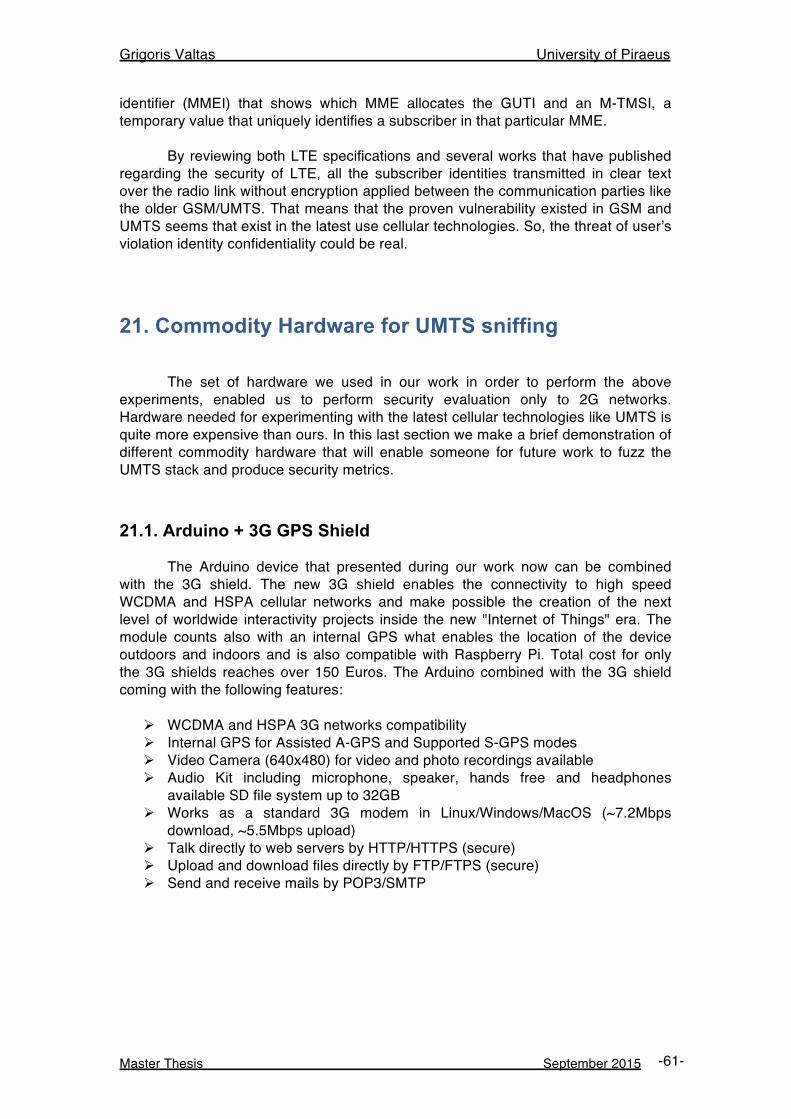
Grigoris Valtas University of Piraeus
Master Thesis September 2015 -61-
identifier (MMEI) that shows which MME allocates the GUTI and an M-TMSI, a temporary value that uniquely identifies a subscriber in that particular MME. By reviewing both LTE specifications and several works that have published regarding the security of LTE, all the subscriber identities transmitted in clear text over the radio link without encryption applied between the communication parties like the older GSM/UMTS. That means that the proven vulnerability existed in GSM and UMTS seems that exist in the latest use cellular technologies. So, the threat of user’s violation identity confidentiality could be real.
21. Commodity Hardware for UMTS sniffing The set of hardware we used in our work in order to perform the above experiments, enabled us to perform security evaluation only to 2G networks. Hardware needed for experimenting with the latest cellular technologies like UMTS is quite more expensive than ours. In this last section we make a brief demonstration of different commodity hardware that will enable someone for future work to fuzz the UMTS stack and produce security metrics.
21.1. Arduino + 3G GPS Shield The Arduino device that presented during our work now can be combined with the 3G shield. The new 3G shield enables the connectivity to high speed WCDMA and HSPA cellular networks and make possible the creation of the next level of worldwide interactivity projects inside the new "Internet of Things" era. The module counts also with an internal GPS what enables the location of the device outdoors and indoors and is also compatible with Raspberry Pi. Total cost for only the 3G shields reaches over 150 Euros. The Arduino combined with the 3G shield coming with the following features:
Ø WCDMA and HSPA 3G networks compatibility Ø Internal GPS for Assisted A-GPS and Supported S-GPS modes Ø Video Camera (640x480) for video and photo recordings available Ø Audio Kit including microphone, speaker, hands free and headphones
available SD file system up to 32GB Ø Works as a standard 3G modem in Linux/Windows/MacOS (~7.2Mbps
download, ~5.5Mbps upload) Ø Talk directly to web servers by HTTP/HTTPS (secure) Ø Upload and download files directly by FTP/FTPS (secure) Ø Send and receive mails by POP3/SMTP
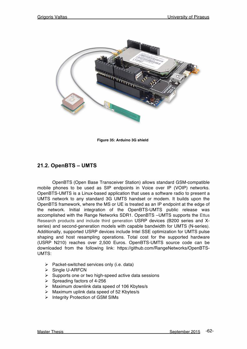
Grigoris Valtas University of Piraeus
Master Thesis September 2015 -62-
Figure 35: Arduino 3G shield
21.2. OpenBTS – UMTS OpenBTS (Open Base Transceiver Station) allows standard GSM-compatible mobile phones to be used as SIP endpoints in Voice over IP (VOIP) networks. OpenBTS-UMTS is a Linux-based application that uses a software radio to present a UMTS network to any standard 3G UMTS handset or modem. It builds upon the OpenBTS framework, where the MS or UE is treated as an IP endpoint at the edge of the network. Initial integration of the OpenBTS-UMTS public release was accomplished with the Range Networks SDR1. OpenBTS –UMTS supports the Ettus Research products and include third generation USRP devices (B200 series and X-series) and second-generation models with capable bandwidth for UMTS (N-series). Additionally, supported USRP devices include Intel SSE optimization for UMTS pulse shaping and host resampling operations. Total cost for the supported hardware (USRP N210) reaches over 2,500 Euros. OpenBTS-UMTS source code can be downloaded from the following link: https://github.com/RangeNetworks/OpenBTS-UMTS:
Ø Packet-switched services only (i.e. data) Ø Single U-ARFCN Ø Supports one or two high-speed active data sessions Ø Spreading factors of 4-256 Ø Maximum downlink data speed of 106 Kbytes/s Ø Maximum uplink data speed of 52 Kbytes/s Ø Integrity Protection of GSM SIMs
Grigoris Valtas University of Piraeus
Master Thesis September 2015 -63-
22. Conclusions
In this thesis we presented two effective attacks that can exploit chronic and fundamental vulnerabilities that exist in the fall back cellular technology, the GSM. These attacks could also have a serious impact at the latest in use cellular technologies like UMTS and LTE. We learned about new come commodity hardware like Arduino and RTL-SDR. Anyone who uses properly Arduino actually has a regular phone with programmable functions. RTL-SDR can be characterized as an IMSI catcher and when combined with Arduino-GSM shield can build a mechanism of mobile user tracking. It is obvious that an individual equipped with that cheap commodity hardware could compromise the GSM subscribers’ privacy and perform silent denial of service attacks. So, systems with broadcast paging protocols can leak location information and the leaks can be observed with the available and low cost commodity hardware presented in this thesis. All these come to exploit the proven vulnerabilities that exist in GSM/UMTS/LTE and related with the expose (in clear text) of the user’s personal identities over the radio link. Both the operators and the security industry are not aware enough about the existence of those attacks we demonstrated in our work. It is also obvious that less money has been spent cellular mobile security needs. Despite security mechanisms like firewalls are implemented, their usability is quite simple and is only for holding connection states and perform traffic shaping. No intelligent security products like Intrusion Detection systems are implemented in order to examine traffic patterns generated in the radio link…
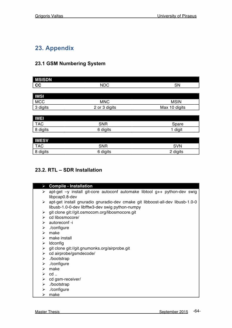
Grigoris Valtas University of Piraeus
Master Thesis September 2015 -64-
23. Appendix
23.1 GSM Numbering System MSISDN CC NDC SN IMSI MCC MNC MSIN 3 digits 2 or 3 digits Max 10 digits IMEI TAC SNR Spare 8 digits 6 digits 1 digit IMESV TAC SNR SVN 8 digits 6 digits 2 digits
23.2. RTL – SDR Installation
Ø Compile - Installation Ø apt-get –y install git-core autoconf automake libtool g++ python-dev swig
libpcap0.8-dev Ø apt-get install gnuradio gnuradio-dev cmake git libboost-all-dev libusb-1.0-0
libusb-1.0-0-dev libfftw3-dev swig python-numpy Ø git clone git://git.osmocom.org/libosmocore.git Ø cd libosmocore/ Ø autoreconf -i Ø ./configure Ø make Ø make install Ø ldconfig Ø git clone git://git.gnumonks.org/airprobe.git Ø cd airprobe/gsmdecode/ Ø ./bootstrap Ø ./configure Ø make Ø cd .. Ø cd gsm-receiver/ Ø ./bootstrap Ø ./configure Ø make
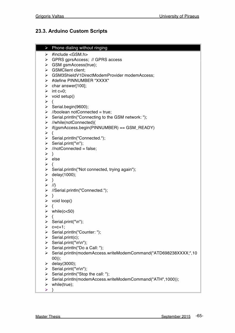
Grigoris Valtas University of Piraeus
Master Thesis September 2015 -65-
23.3. Arduino Custom Scripts
Ø Phone dialing without ringing Ø #include <GSM.h> Ø GPRS gprsAccess; // GPRS access Ø GSM gsmAccess(true); Ø GSMClient client; Ø GSM3ShieldV1DirectModemProvider modemAccess; Ø #define PINNUMBER "XXXX" Ø char answer[100]; Ø int c=0; Ø void setup() Ø { Ø Serial.begin(9600); Ø //boolean notConnected = true; Ø Serial.println("Connecting to the GSM network: "); Ø //while(notConnected){ Ø if(gsmAccess.begin(PINNUMBER) == GSM_READY) Ø { Ø Serial.println("Connected."); Ø Serial.print("\n"); Ø //notConnected = false; Ø } Ø else Ø { Ø Serial.println("Not connected, trying again"); Ø delay(1000); Ø } Ø //} Ø //Serial.println("Connected."); Ø } Ø void loop() Ø { Ø while(c<50) Ø { Ø Serial.print("\n"); Ø c=c+1; Ø Serial.println("Counter: "); Ø Serial.print(c); Ø Serial.print("\n\n"); Ø Serial.println("Do a Call: "); Ø Serial.println(modemAccess.writeModemCommand("ATD698238XXXX;",10
00)); Ø delay(3000); Ø Serial.print("\n\n"); Ø Serial.println("Stop the call: "); Ø Serial.println(modemAccess.writeModemCommand("ATH",1000)); Ø while(true); Ø }
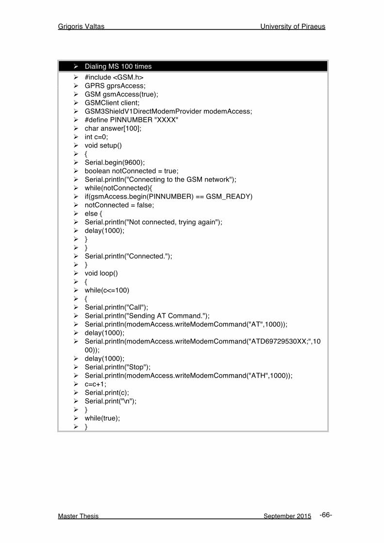
Grigoris Valtas University of Piraeus
Master Thesis September 2015 -66-
Ø Dialing MS 100 times Ø #include <GSM.h> Ø GPRS gprsAccess; Ø GSM gsmAccess(true); Ø GSMClient client; Ø GSM3ShieldV1DirectModemProvider modemAccess; Ø #define PINNUMBER "XXXX" Ø char answer[100]; Ø int c=0; Ø void setup() Ø { Ø Serial.begin(9600); Ø boolean notConnected = true; Ø Serial.println("Connecting to the GSM network"); Ø while(notConnected){ Ø if(gsmAccess.begin(PINNUMBER) == GSM_READY) Ø notConnected = false; Ø else { Ø Serial.println("Not connected, trying again"); Ø delay(1000); Ø } Ø } Ø Serial.println("Connected."); Ø } Ø void loop() Ø { Ø while(c<=100) Ø { Ø Serial.println("Call"); Ø Serial.println("Sending AT Command."); Ø Serial.println(modemAccess.writeModemCommand("AT",1000)); Ø delay(1000); Ø Serial.println(modemAccess.writeModemCommand("ATD69729530XX;",10
00)); Ø delay(1000); Ø Serial.println("Stop"); Ø Serial.println(modemAccess.writeModemCommand("ATH",1000)); Ø c=c+1; Ø Serial.print(c); Ø Serial.print("\n"); Ø } Ø while(true); Ø }
Grigoris Valtas University of Piraeus
Master Thesis September 2015 -67-
24. References
1. http://www.ericsson.com/res/docs/2014/ericsson-mobility-report-june-2014.pdf 2. Christos Xenakis, "Malicious actions against the GPRS technology," Computer
Virology, Springer, Vol. 2, No. 2, Nov. 2006, pp. 121-133 3. 3GPP TS 03.6 (V7.9.0), ”GPRS Service Description, Stage 2”, Sept. 2002. 4. http://www.3gpp.org/dynareport/36-series.htm 5. 3GPP TS 04.01 V8.0.0 – Mobile Station - Base Station System (MS - BSS)
interface; General aspects and principles. http://www.3gpp.org/ftp/Specs/html-info/0401.htm, March 2000.
6. The mobile economy, GSMA, 2014 7. Arduino, The Open Source Electronics Platform, http://arduino.cc 8. The osmocombb project – open source gsm baseband software
implementation. http://bb.osmocom.org/ 9. Christos Xenakis, Christoforos Ntantogian, “An advanced persistent threat in
3G networks: Attacking the home network from roaming networks,” Computers & Security, Elsevier Science, Vol. 40, Issue 1, pp:84-94, February 2014.
10. 3GPP TS 27.007 V11.5.0 (2012-12), 3rd Generation Partnership Project, Technical Specification Group Core Network and Terminals, AT command set for User Equipment (UE) (Release 11).
11. http://www.3glteinfo.com/umts-security-user-identity-confidentiality-imsi-tmsi-p-tmsi/
12. Nico Golde, Kévin Redon, Jean-Pierre Seifert, “Let me answer that for you: exploiting broadcast information in cellular networks”, 22nd USENIX conference on Security, Washington DC, USA, Aug. 2013.
13. http://www.sharetechnote.com/html/Handbook_LTE_IDs_in_LTE.html 14. Denis Foo Kune, John Koelndorfer, Nicholas Hopper, Yongdae Kim, “Location
Leaks on the GSM Air Interface”, Network & Distributed System Security Symposium (NDSS) 2012, San Diego, California, USA.
15. Patrick Traynor, Michael Lin, Machigar Ongtang, Vikhyath Rao, Trent Jaeger, Patrick Drew McDaniel, Thomas F. La Porta, “On cellular botnets: measuring the impact of malicious devices on a cellular network core”, ACM Conference on Computer and Communications Security, 223-234, 2009.
16. Myrto Arapinis, Loretta Ilaria Mancini, Eike Ritter, Mark Ryan, “Privacy through Pseudonymity in Mobile Telephony Systems”, 21st Network and Distributed System Security Symposium (NDSS) 2014, California, USA.
17. http://www.rtl-sdr.com/ 18. Karsten Nohl, “Attacking phone privacy”, BlackHat USA, Las Vegas, Aug 2010 19. http://www.pathintelligence.com 20. http://www.smart-flows.com 21. https://www.blackhat.com/us-14/briefings.html 22. http://www.theregister.co.uk/2012/01/11/phone_tracking_expert/ 23. Patrick P. C. Lee, Tian Bu, Thomas Y. C. Woo, “On the Detection of Signaling
DoS Attacks on 3G/WiMax Wireless Networks”, Elsevier Science, Computer Networks Volume 53 Issue 15, October 2009
24. Christos Xenakis, Christoforos Ntantogian, “Attacking the Baseband Modem of Mobile Phones to Breach the Users’ Privacy and Network Security”, 7th International Conference on Cyber Conflict (CyCon 2015), Tallinn, Estonia, May 2015.
Grigoris Valtas University of Piraeus
Master Thesis September 2015 -68-
25. Behnam Sattarzadeh, Mahdi Asadpour, and Rasool Jalili Computer Engineering Department, Sharif University of Technology, Tehran, Iran, “Improved User Identity Confidentiality for UMTS Mobile Networks
26. Enhancement Mobile Security and User Confidentiality for UMTS 27. David Perez – Jose Pico, “A practical attack against
GPRS/EDGE/UMTS/HSPA mobile data communications 28. Christoforos Ntantogian, Grigoris Valtas, Nikos Kapetanakis, Faidon
Lalagiannis, “Attacking GSM Networks as a Script Kiddie Using Commodity Hardware and Software.
29. Jeremy Serror, Hui Zang, Jean C. Bolot, “Impact of Paging Channel Overloads or Attacks on a Cellular Network
30. Nathaniel Husted, Steven Myers, “Mobile Location Tracking in Metro Areas: Malnets and Others
31. Yubo Song, Kan Zhou, Xi Chen, “Fake BTS Attacks on GSM System on Software Radio Platform
32. Yoni De Mulder, George Danezis, Bart Preneel, “Identification via Location-Profiling in GSM Networks
33. http://openbts.org/w/index.php/OpenBTS-UMTS 34. http://www.ettus.com/ 35. http://www.rangenetworks.com/press/range-networks-enhances-openbts-with-
3g-data-capability