Section 15: Introduction to Stress and Bending SHEAR AND MOMENT • In order to design a beam, it is...
24
Section 15: Introduction to Stress and Bending 15-1
Transcript of Section 15: Introduction to Stress and Bending SHEAR AND MOMENT • In order to design a beam, it is...
Section 15: Introduction to Stress and Bending
15-1
BendingBending
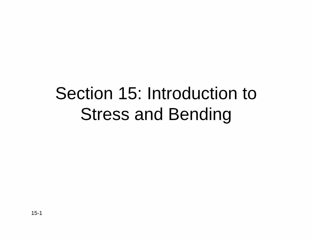
• Long bones: beamsLong bones: beams• Compressive stress:
inner portion
T
p• Tensile stress: outer
portion Ci
p• Max stresses near the
edges, less near the
axis
axisneutral axis
(M )/I
yaxis
15-2 From: Noffal
σx=(Mb·y)/I
Bending MomentsBending Moments
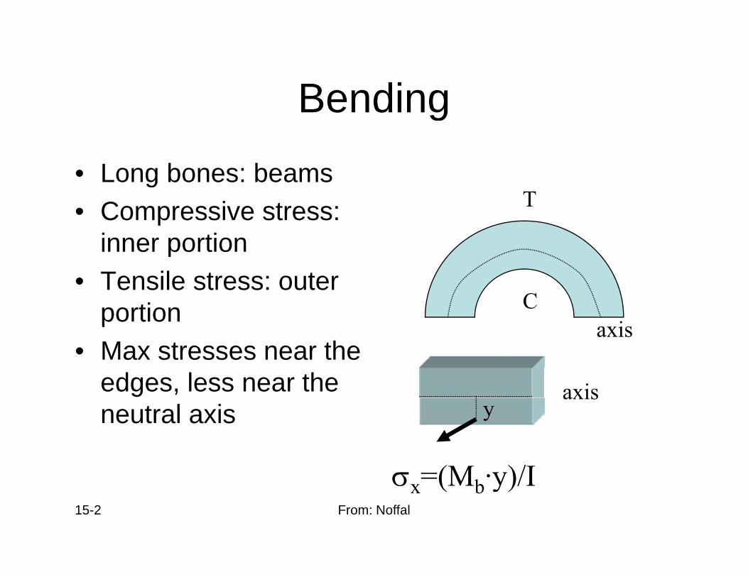
• Shear stresses maxShear stresses max at neutral axis and zero at the surface Q
• τ = (Q·V)/(I ·b)• Q= area moment
Q
y• V= vertical shear
forceh
y
b
15-3 From: Noffal
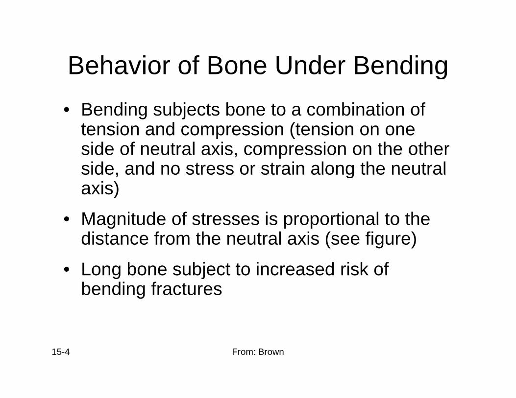
Behavior of Bone Under BendingBehavior of Bone Under Bending• Bending subjects bone to a combination of
t i d i (t itension and compression (tension on one side of neutral axis, compression on the other side, and no stress or strain along the neutralside, and no stress or strain along the neutral axis)
• Magnitude of stresses is proportional to theMagnitude of stresses is proportional to the distance from the neutral axis (see figure)
• Long bone subject to increased risk ofLong bone subject to increased risk of bending fractures
15-4 From: Brown
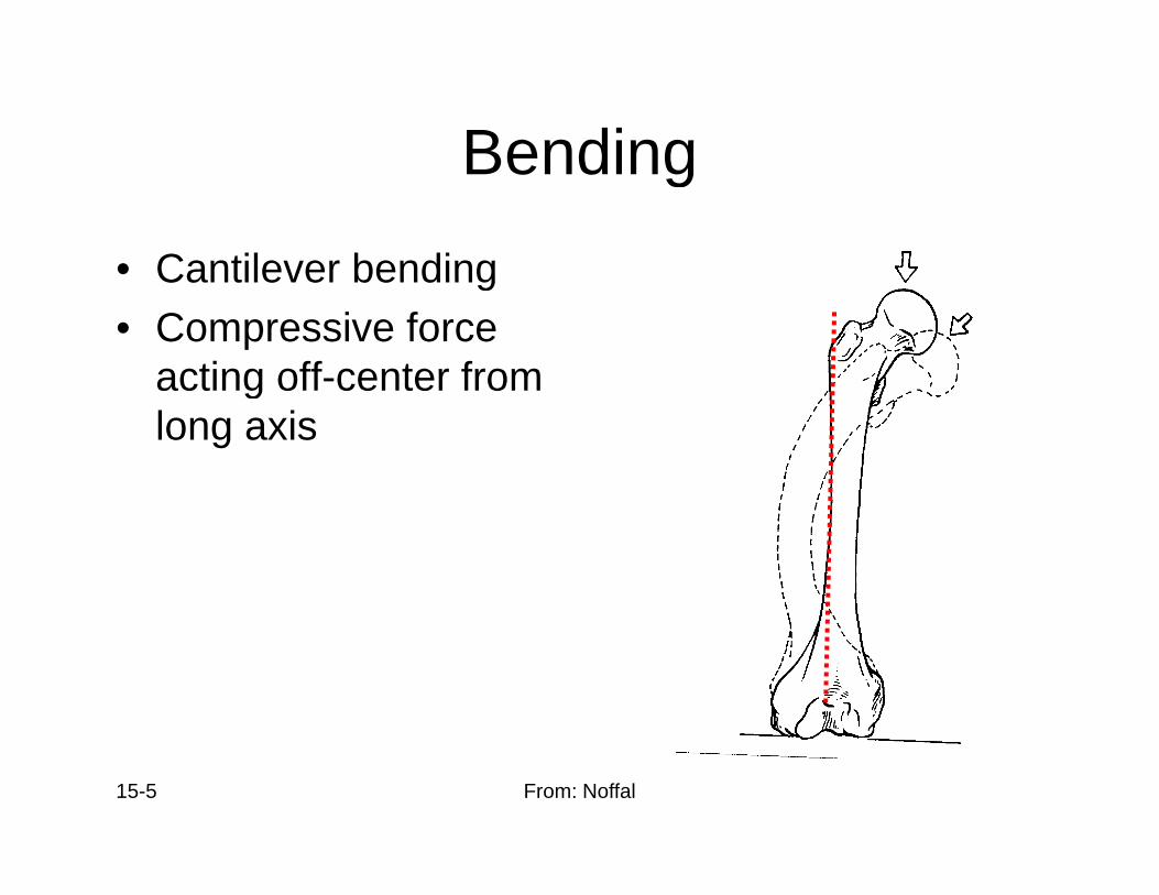
BendingBending
• Cantilever bendingCantilever bending• Compressive force
acting off-center from glong axis
15-5 From: Noffal
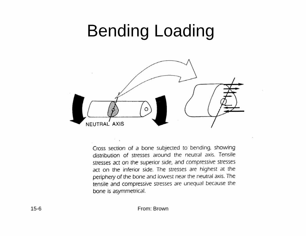
Bending Loading
15-6 From: Brown
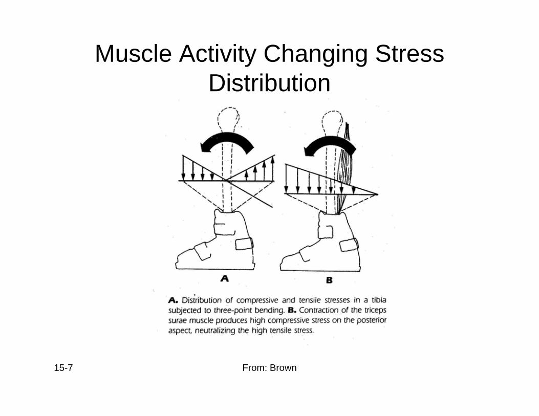
Muscle Activity Changing Stress Di t ib tiDistribution
15-7 From: Brown
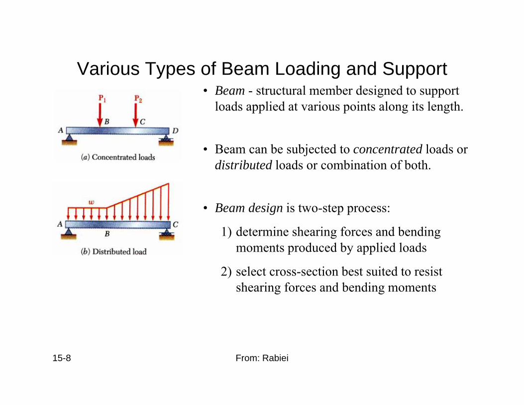
Various Types of Beam Loading and Supporta ous ypes o ea oad g a d Suppo t• Beam - structural member designed to support
loads applied at various points along its length.
• Beam can be subjected to concentrated loads or distributed loads or combination of both.
• Beam design is two-step process:
1) d t i h i f d b di1) determine shearing forces and bending moments produced by applied loads
2) select cross-section best suited to resist shearing forces and bending moments
15-8 From: Rabiei
6.1 SHEAR AND MOMENT DIAGRAMSDIAGRAMS• In order to design a beam, it is necessary to
determine the maximum shear and moment in the beam
• Express V and M as functions of arbitrary position x along axis.
• These functions can be represented by graphs called shear and moment diagrams
• Engineers need to know the variation of shear and t l th b t k h tmoment along the beam to know where to
reinforce it
15-9 From: Wang
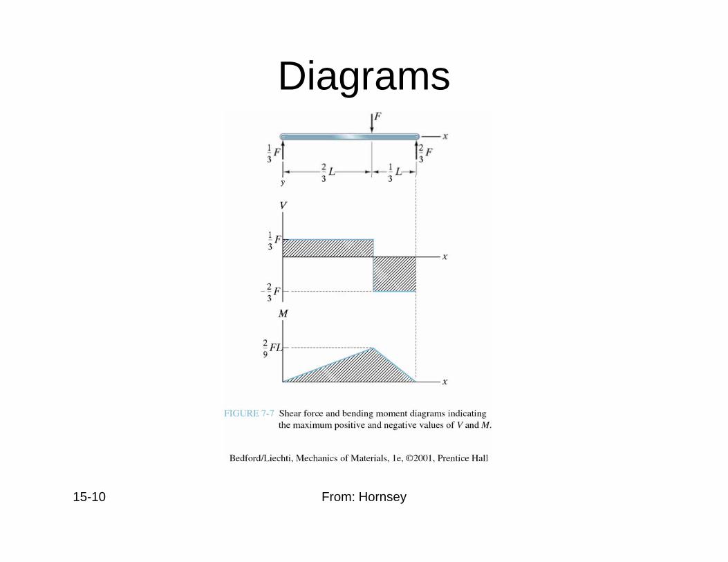
Diagrams
15-10 From: Hornsey
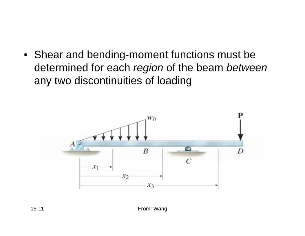
6.1 SHEAR AND MOMENT DIAGRAMSDIAGRAMS• Shear and bending-moment functions must be
determined for each region of the beam betweengany two discontinuities of loading
15-11 From: Wang
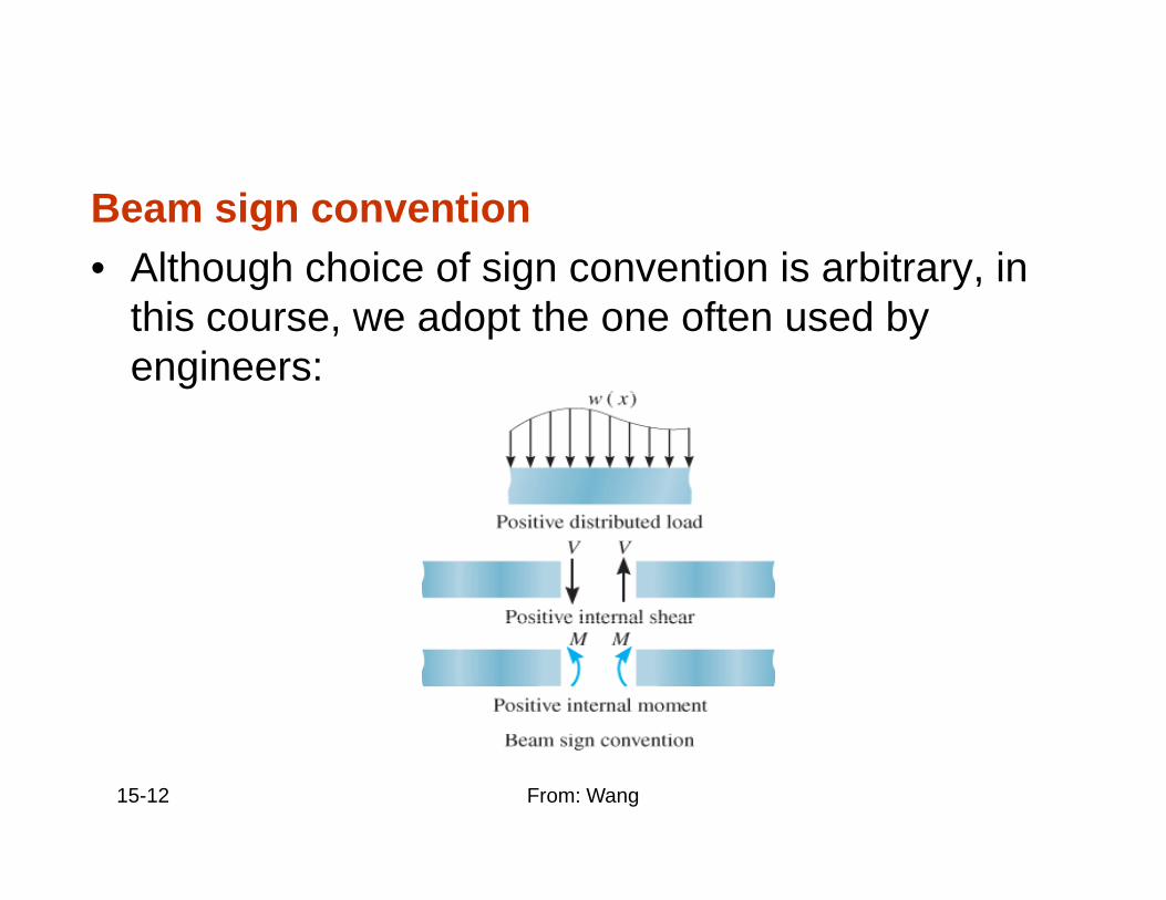
6.1 SHEAR AND MOMENT DIAGRAMSDIAGRAMSBeam sign convention
• Although choice of sign convention is arbitrary, inAlthough choice of sign convention is arbitrary, in this course, we adopt the one often used by engineers:
15-12 From: Wang
6.1 SHEAR AND MOMENT DIAGRAMSDIAGRAMSProcedure for analysis
Support reactions• Determine all reactive forces and couple moments
acting on beam• Resolve all forces into components actingResolve all forces into components acting
perpendicular and parallel to beam’s axisShear and moment functions• Specify separate coordinates x having an origin at
beam’s left end, and extending to regions of beam between concentrated forces and/or couple pmoments, or where there is no discontinuity of distributed loading
15-13 From: Wang
6.1 SHEAR AND MOMENT DIAGRAMSDIAGRAMSProcedure for analysis
Shear and moment functions• Section beam perpendicular to its axis at each
distance x• Draw free-body diagram of one segmentDraw free body diagram of one segment• Make sure V and M are shown acting in positive
sense, according to sign convention• Sum forces perpendicular to beam’s axis to get
shear• Sum moments about the sectioned end of segmentSum moments about the sectioned end of segment
to get moment
15-14 From: Wang
6.1 SHEAR AND MOMENT DIAGRAMSDIAGRAMSProcedure for analysis
Shear and moment diagrams• Plot shear diagram (V vs. x) and moment diagram
(M vs. x)• If numerical values are positive values are plottedIf numerical values are positive, values are plotted
above axis, otherwise, negative values are plotted below axisIt is con enient to sho the shear and moment• It is convenient to show the shear and moment diagrams directly below the free-body diagram
15-15 From: Wang
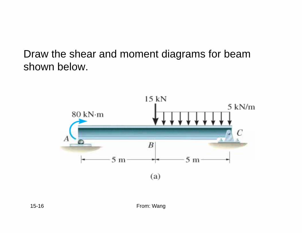
EXAMPLE 6 6EXAMPLE 6.6Draw the shear and moment diagrams for beam shown below.
15-16 From: Wang
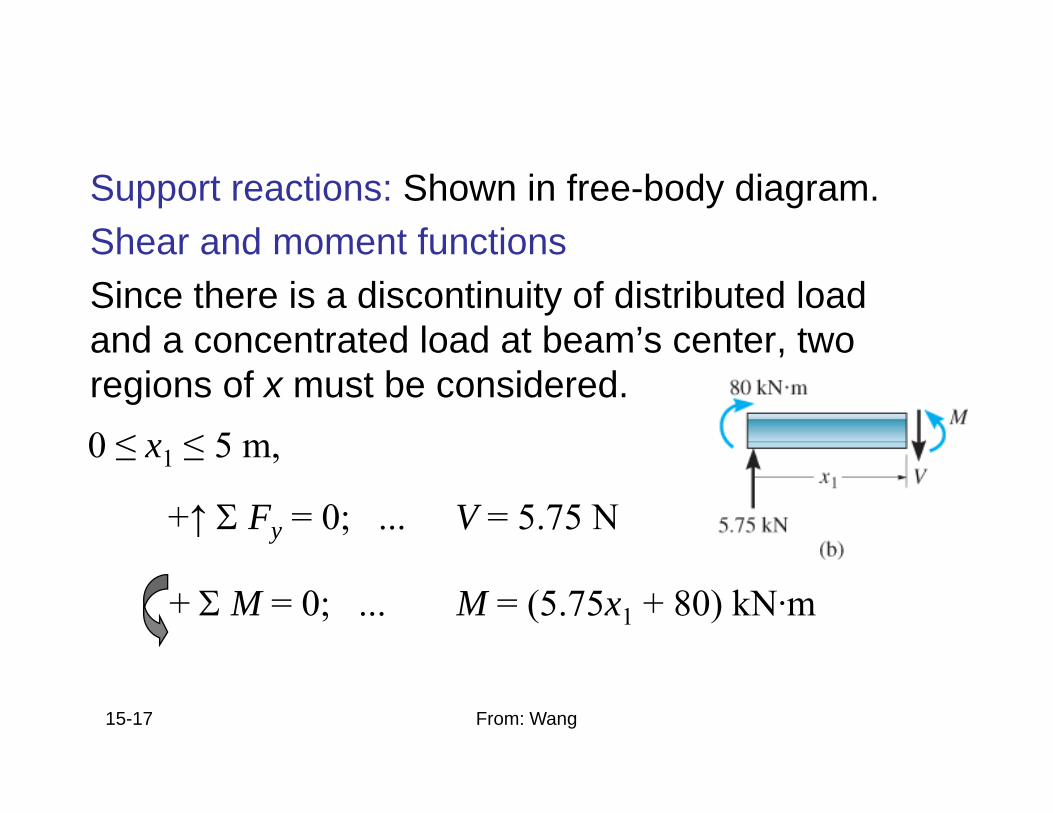
EXAMPLE 6 6 (SOLN)EXAMPLE 6.6 (SOLN)Support reactions: Shown in free-body diagram.Shear and moment functionsShear and moment functionsSince there is a discontinuity of distributed load and a concentrated load at beam’s center, two ,regions of x must be considered.0 ≤ x1 ≤ 5 m, ≤ 1 ≤ ,
+↑ Σ Fy = 0; ... V = 5.75 N
+ Σ M = 0; ... M = (5.75x1 + 80) kN·m
15-17 From: Wang
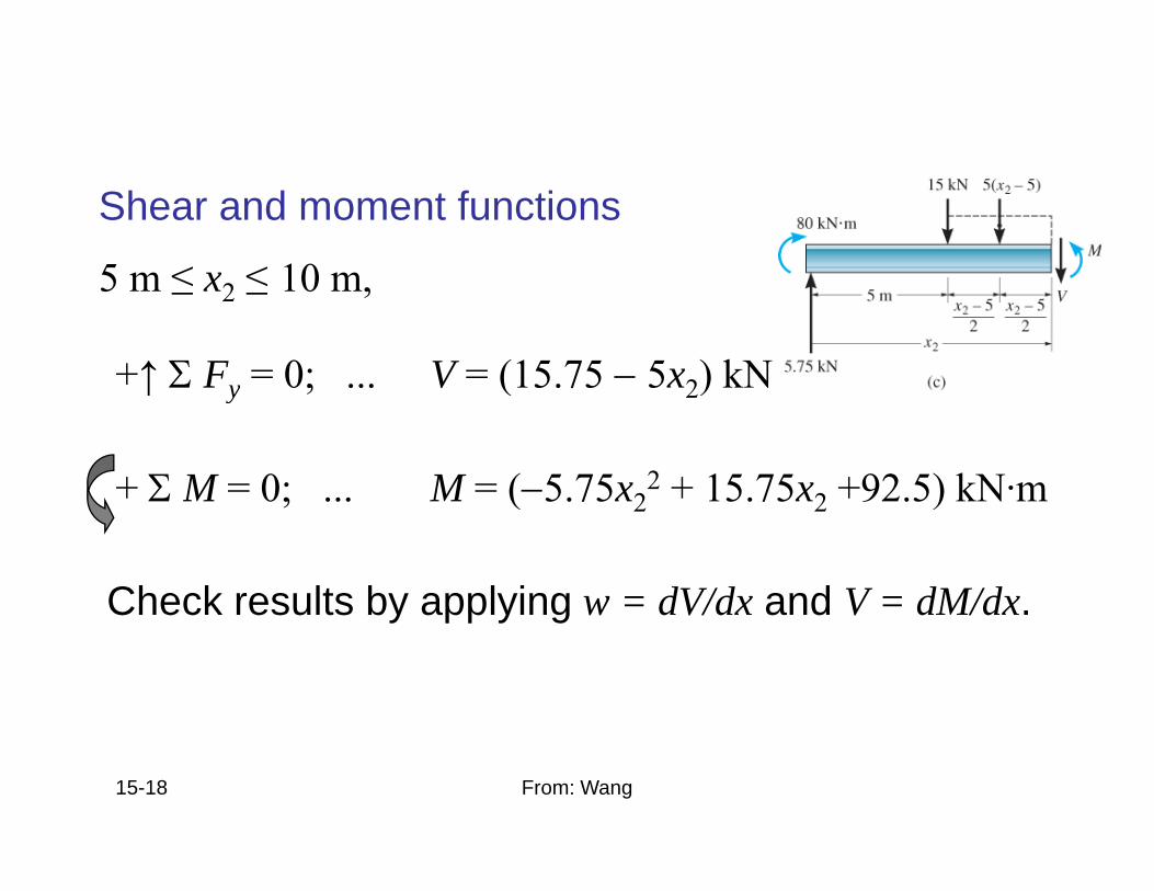
EXAMPLE 6 6 (SOLN)EXAMPLE 6.6 (SOLN)Shear and moment functions
5 m ≤ x ≤ 10 m5 m ≤ x2 ≤ 10 m,
+↑ Σ Fy = 0; ... V = (15.75 − 5x2) kN↑ y ; ( 2)
+ Σ M = 0; ... M = (−5.75x22 + 15.75x2 +92.5) kN·m; ( 2 2 )
Check results by applying w = dV/dx and V = dM/dx.Check results by applying w dV/dx and V dM/dx.
15-18 From: Wang
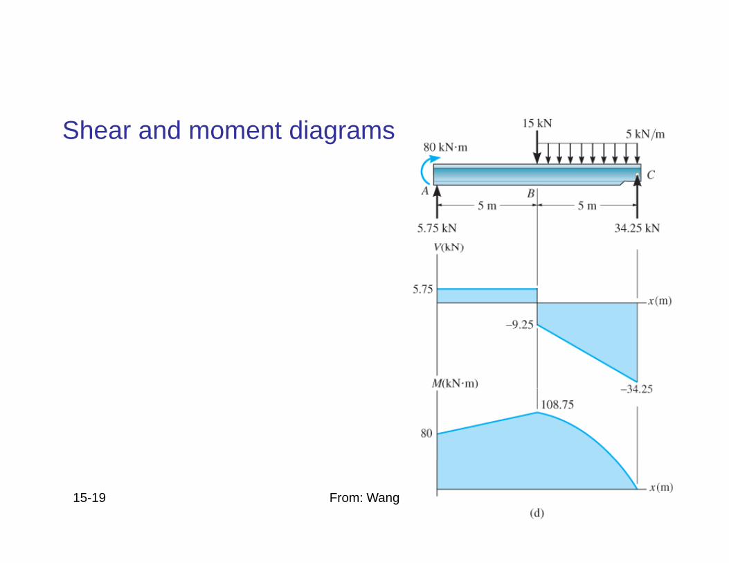
EXAMPLE 6 6 (SOLN)EXAMPLE 6.6 (SOLN)Shear and moment diagrams
15-19 From: Wang
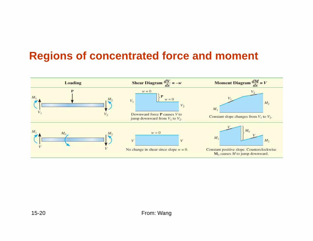
6.2 GRAPHICAL METHOD FOR CONSTRUCTING SHEAR AND MOMENTCONSTRUCTING SHEAR AND MOMENT
DIAGRAMSRegions of concentrated force and moment
15-20 From: Wang
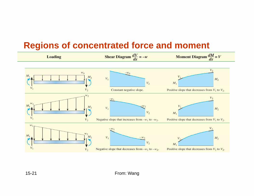
6.2 GRAPHICAL METHOD FOR CONSTRUCTING SHEAR AND MOMENTCONSTRUCTING SHEAR AND MOMENT
DIAGRAMSRegions of concentrated force and moment
15-21 From: Wang
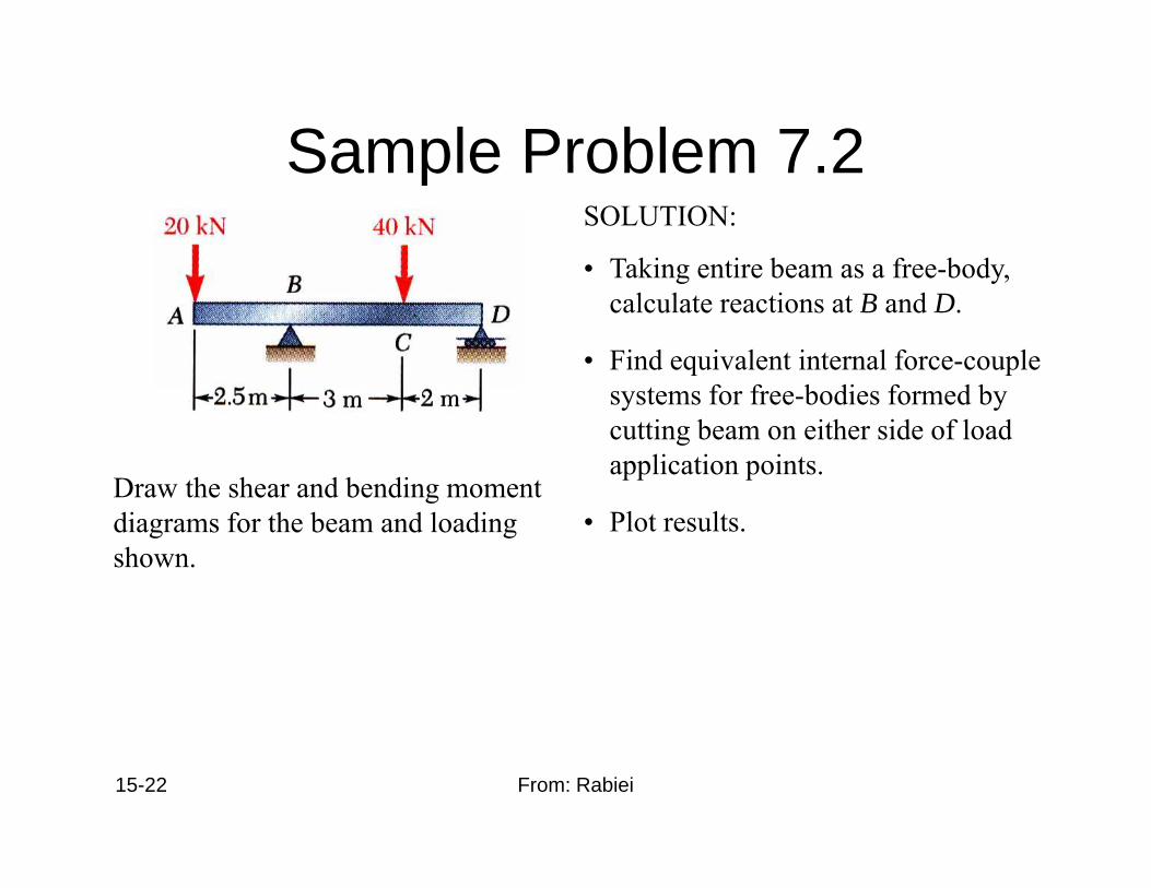
Sample Problem 7 2Sample Problem 7.2SOLUTION:
• Taking entire beam as a free-body,Taking entire beam as a free body, calculate reactions at B and D.
• Find equivalent internal force-couple t f f b di f d b
Draw the shear and bending moment
systems for free-bodies formed by cutting beam on either side of load application points.
gdiagrams for the beam and loading shown.
• Plot results.
15-22 From: Rabiei
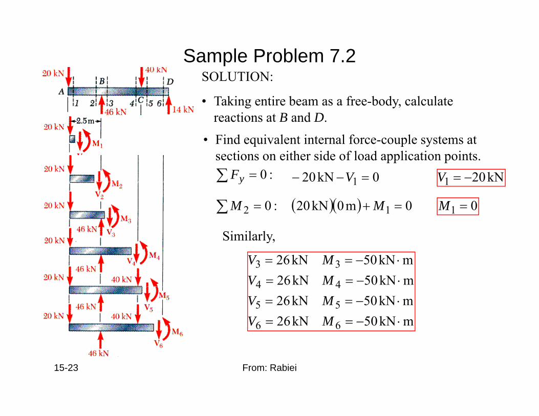
Sample Problem 7.2SOLUTION:SOLUTION:
• Taking entire beam as a free-body, calculate reactions at B and D.
• Find equivalent internal force-couple systems at sections on either side of load application points. ∑ = :0yF 0kN20 1 =−− V kN201 −=V∑ y 1 1
:02 =∑M ( )( ) 0m0kN20 1 =+ M 01 =M
Similarly
mkN50kN26mkN50kN26
44
33⋅−==⋅−==
MVMV
Similarly,
mkN50kN26mkN50kN26
66
55
44
⋅−==⋅−==
MVMV
15-23 From: Rabiei
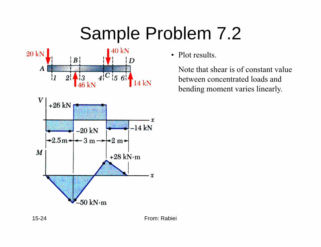
Sample Problem 7.2• Plot results.
Note that shear is of constant value b d l d dbetween concentrated loads and bending moment varies linearly.
15-24 From: Rabiei