SDS A1200-08 VORTEX FLOWMETER - Global Gateway · PDF fileTemperature (°F) Pressure ......
4
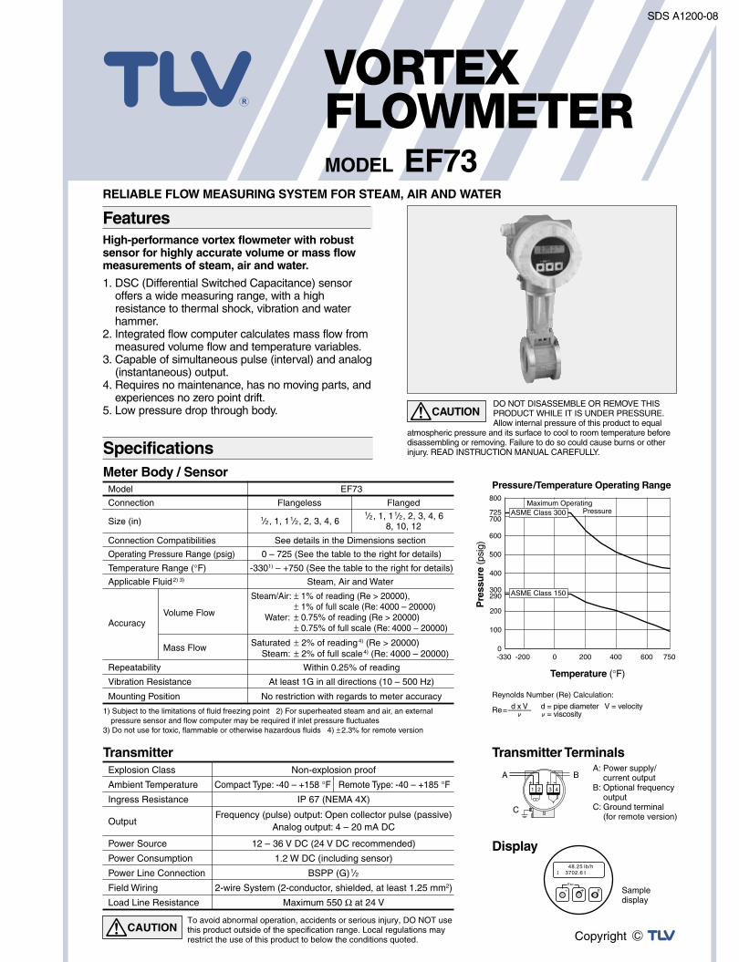
Meter Body / Sensor Transmitter Terminals Pressure/Temperature Operating Range Temperature (°F) Pressure (psig) Display Transmitter Re=——— Reynolds Number (Re) Calculation: ν d = pipe diameter V = velocity ν= viscosity d x V 1) Subject to the limitations of fluid freezing point 2) For superheated steam and air, an external pressure sensor and flow computer may be required if inlet pressure fluctuates 3) Do not use for toxic, flammable or otherwise hazardous fluids 4) ± 2.3% for remote version -330 -200 0 100 200 300 400 0 200 400 600 750 500 600 700 800 290 725 12 34 + - + - Esc E + - 48.25 lb/h 3702.6 t I Connection Size (in) Connection Compatibilities Operating Pressure Range (psig) Temperature Range (°F) Applicable Fluid 2) 3) Accuracy Repeatability Vibration Resistance Volume Flow Mass Flow 0 – 725 (See the table to the right for details) -330 1) – +750 (See the table to the right for details) Steam, Air and Water Steam/Air: ± 1% of reading (Re > 20000), ± 1% of full scale (Re: 4000 – 20000) Water: ± 0.75% of reading (Re > 20000) ± 0.75% of full scale (Re: 4000 – 20000) Saturated ± 2% of reading 4) (Re > 20000) Steam: ± 2% of full scale 4) (Re: 4000 – 20000) Within 0.25% of reading At least 1G in all directions (10 – 500 Hz) Flangeless Flanged a/B, 1, 1a/B, 2, 3, 4, 6 a/B, 1, 1a/B, 2, 3, 4, 6 8, 10, 12 See details in the Dimensions section Model EF73 Mounting Position No restriction with regards to meter accuracy Explosion Class Ambient Temperature Ingress Resistance Output Power Source Power Consumption Power Line Connection Field Wiring Load Line Resistance Non-explosion proof Compact Type: -40 – +158 °F Remote Type: -40 – +185 °F IP 67 (NEMA 4X) Frequency (pulse) output: Open collector pulse (passive) Analog output: 4 – 20 mA DC 12 – 36 V DC (24 V DC recommended) 1.2 W DC (including sensor) BSPP (G)a/B 2-wire System (2-conductor, shielded, at least 1.25 mm 2 ) Maximum 550 Ω at 24 V B A C To avoid abnormal operation, accidents or serious injury, DO NOT use this product outside of the specification range. Local regulations may restrict the use of this product to below the conditions quoted. CAUTION Sample display A: Power supply/ current output B: Optional frequency output C: Ground terminal (for remote version) ASME Class 300 ASME Class 150 Maximum Operating Pressure Specifications SDS A1200-08 MODEL EF73 VORTEX FLOWMETER High-performance vortex flowmeter with robust sensor for highly accurate volume or mass flow measurements of steam, air and water. 1. DSC (Differential Switched Capacitance) sensor offers a wide measuring range, with a high resistance to thermal shock, vibration and water hammer. 2. Integrated flow computer calculates mass flow from measured volume flow and temperature variables. 3. Capable of simultaneous pulse (interval) and analog (instantaneous) output. 4. Requires no maintenance, has no moving parts, and experiences no zero point drift. 5. Low pressure drop through body. RELIABLE FLOW MEASURING SYSTEM FOR STEAM, AIR AND WATER DO NOT DISASSEMBLE OR REMOVE THIS PRODUCT WHILE IT IS UNDER PRESSURE. Allow internal pressure of this product to equal atmospheric pressure and its surface to cool to room temperature before disassembling or removing. Failure to do so could cause burns or other injury. READ INSTRUCTION MANUAL CAREFULLY. CAUTION Features
Transcript of SDS A1200-08 VORTEX FLOWMETER - Global Gateway · PDF fileTemperature (°F) Pressure ......
Meter Body / Sensor
Transmitter Terminals
Pressure/Temperature Operating Range
Temperature (°F)
Pre
ssu
re (p
sig)
Display
Transmitter
Re=———
Reynolds Number (Re) Calculation:
νd = pipe diameter V = velocity ν = viscosity
d x V1) Subject to the limitations of fluid freezing point 2) For superheated steam and air, an external
pressure sensor and flow computer may be required if inlet pressure fluctuates3) Do not use for toxic, flammable or otherwise hazardous fluids 4) ±2.3% for remote version
-330 -2000
100
200
300
400
0 200 400 600 750
500
600
700
800
290
725
1 2 3 4+ - + -
Esc
E+-
48.25 lb/h3702.6 tI
Connection
Size (in)
Connection Compatibilities
Operating Pressure Range (psig)
Temperature Range (°F)
Applicable Fluid2) 3)
Accuracy
Repeatability
Vibration Resistance
Volume Flow
Mass Flow
0 – 725 (See the table to the right for details)
-3301) – +750 (See the table to the right for details)
Steam, Air and Water
Steam/Air: ± 1% of reading (Re > 20000), ± 1% of full scale (Re: 4000 – 20000) Water: ± 0.75% of reading (Re > 20000) ± 0.75% of full scale (Re: 4000 – 20000)
Saturated ± 2% of reading4) (Re > 20000) Steam: ± 2% of full scale4) (Re: 4000 – 20000)
Within 0.25% of reading
At least 1G in all directions (10 – 500 Hz)
Flangeless Flanged
a/B, 1, 1a/B, 2, 3, 4, 6 a/B, 1, 1a/B, 2, 3, 4, 68, 10, 12
See details in the Dimensions section
Model EF73
Mounting Position No restriction with regards to meter accuracy
Explosion Class
Ambient Temperature
Ingress Resistance
Output
Power Source
Power Consumption
Power Line Connection
Field Wiring
Load Line Resistance
Non-explosion proof
Compact Type: -40 – +158 °F Remote Type: -40 – +185 °F
IP 67 (NEMA 4X)
Frequency (pulse) output: Open collector pulse (passive)Analog output: 4 – 20 mA DC
12 – 36 V DC (24 V DC recommended)
1.2 W DC (including sensor)
BSPP (G)a/B
2-wire System (2-conductor, shielded, at least 1.25 mm2)
Maximum 550 Ω at 24 V
BA
C
To avoid abnormal operation, accidents or serious injury, DO NOT use this product outside of the specification range. Local regulations may restrict the use of this product to below the conditions quoted.
CAUTION
Sample display
A: Power supply/ current outputB: Optional frequency outputC: Ground terminal (for remote version)
ASME Class 300
ASME Class 150
Maximum OperatingPressure
Specifications
SDS A1200-08
MODEL EF73
VORTEXFLOWMETER
High-performance vortex flowmeter with robustsensor for highly accurate volume or mass flowmeasurements of steam, air and water.
1. DSC (Differential Switched Capacitance) sensoroffers a wide measuring range, with a highresistance to thermal shock, vibration and waterhammer.
2. Integrated flow computer calculates mass flow frommeasured volume flow and temperature variables.
3. Capable of simultaneous pulse (interval) and analog(instantaneous) output.
4. Requires no maintenance, has no moving parts, andexperiences no zero point drift.
5. Low pressure drop through body.
RELIABLE FLOW MEASURING SYSTEM FOR STEAM, AIR AND WATER
DO NOT DISASSEMBLE OR REMOVE THISPRODUCT WHILE IT IS UNDER PRESSURE.Allow internal pressure of this product to equal
atmospheric pressure and its surface to cool to room temperature beforedisassembling or removing. Failure to do so could cause burns or otherinjury. READ INSTRUCTION MANUAL CAREFULLY.
CAUTION
Features
SDS A1200-08
EscEsc
E-- ++
50D 5D
A B
EscEsc
E- +
15D 5D
EscEsc
E- +
50D 5DEscEsc
E- +
8D5D 5D
EscEsc
E- +
8D5D 5DA B
A B A B
A B A B
A B A B
A B A B
A B A B
A B A B
A B A B
EscEsc
E- +
8D2D 5D
EscEsc
E- +
18D 5DEscEsc
E- +
8D2D+5h
h
5D
EscEsc
E- +
25D 5DEscEsc
E- +
8D5D 5D
EscEsc
E- +
20D 5DEscEsc
E- +
8D2D 5D
EscEsc
E- +
25D 5D
EscEsc
E- +
40D 5D
EscEsc
E- +
8D5D 5D
EscEsc
E- +
8D5D 5D
Flow Conditioner
Flow Conditioner
Flow Conditioner
Flow Conditioner
Flow Conditioner
Flow Conditioner
Flow Conditioner
Flow Conditioner
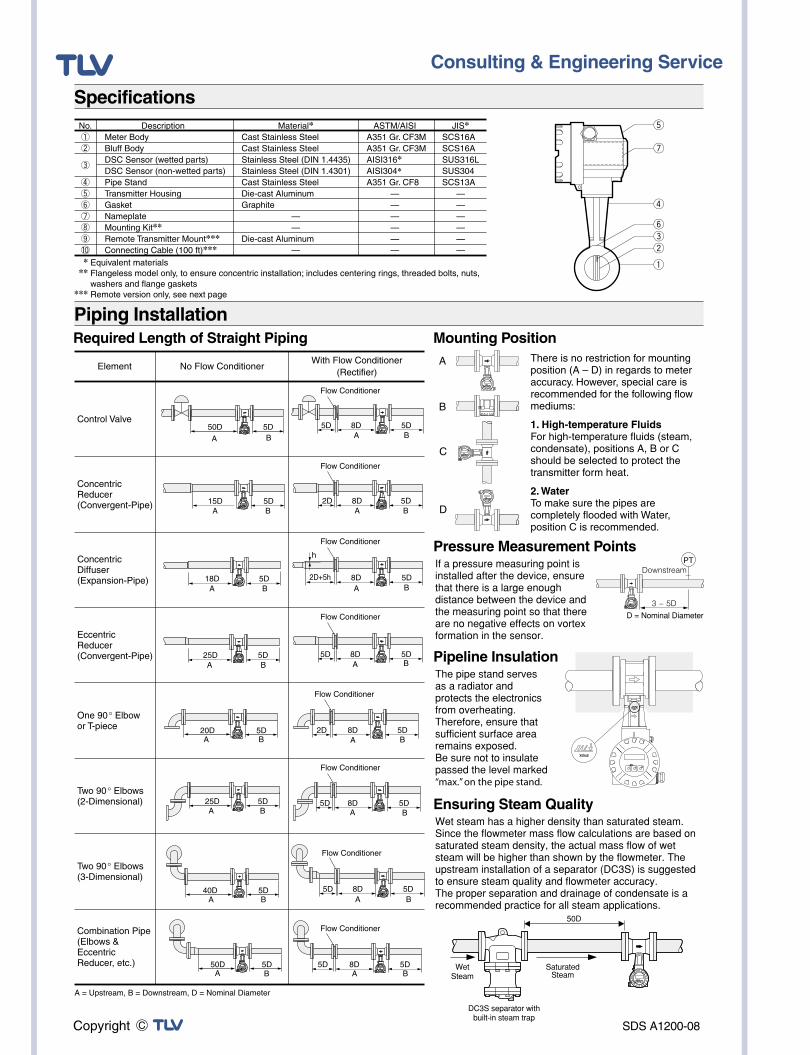
Mounting Position
Pipeline Insulation
C
D
A
B
Ensuring Steam Quality
* Equivalent materials ** Flangeless model only, to ensure concentric installation; includes centering rings, threaded bolts, nuts,
washers and flange gaskets*** Remote version only, see next page
EscEsc
E- +
EscEsc
E- +
EscEsc
E- +
There is no restriction for mounting position (A – D) in regards to meter accuracy. However, special care is recommended for the following flow mediums:
1. High-temperature FluidsFor high-temperature fluids (steam, condensate), positions A, B or C should be selected to protect the transmitter form heat.
2. WaterTo make sure the pipes are completely flooded with Water, position C is recommended.
The pipe stand serves as a radiator and protects the electronics from overheating. Therefore, ensure that sufficient surface area remains exposed.Be sure not to insulate passed the level marked “max.” on the pipe stand.
If a pressure measuring point is installed after the device, ensure that there is a large enough distance between the device and the measuring point so that there are no negative effects on vortex formation in the sensor.
Wet steam has a higher density than saturated steam.Since the flowmeter mass flow calculations are based on saturated steam density, the actual mass flow of wet steam will be higher than shown by the flowmeter. The upstream installation of a separator (DC3S) is suggested to ensure steam quality and flowmeter accuracy.The proper separation and drainage of condensate is a recommended practice for all steam applications.
EscEsc
E- +
Specifications
Piping Installation
t
u
r
yew
q
Pressure Measurement PointsPT
Downstream
3 – 5DEsc
E- +
Esc
E- +
50D
SaturatedSteam
WetSteam
DC3S separator withbuilt-in steam trap
No.①②
③
④⑤⑥⑦⑧⑨⑩
DescriptionMeter BodyBluff BodyDSC Sensor (wetted parts)DSC Sensor (non-wetted parts)Pipe StandTransmitter HousingGasketNameplateMounting Kit**Remote Transmitter Mount***Connecting Cable (100 ft)***
Material*Cast Stainless Steel Cast Stainless SteelStainless Steel (DIN 1.4435)Stainless Steel (DIN 1.4301)Cast Stainless Steel Die-cast Aluminum Graphite — —Die-cast Aluminum —
JIS*SCS16ASCS16ASUS316LSUS304SCS13A — — — — — —
ASTM/AISIA351 Gr. CF3MA351 Gr. CF3MAISI316*AISI304*A351 Gr. CF8 — — — — — —
D = Nominal Diameter
Required Length of Straight Piping
A = Upstream, B = Downstream, D = Nominal Diameter
Control Valve
Concentric Reducer (Convergent-Pipe)
Concentric Diffuser (Expansion-Pipe)
Eccentric Reducer (Convergent-Pipe)
One 90° Elbow or T-piece
Two 90° Elbows (2-Dimensional)
Two 90° Elbows (3-Dimensional)
Combination Pipe (Elbows & Eccentric Reducer, etc.)
Element No Flow ConditionerWith Flow Conditioner
(Rectifier)
SDS A1200-08
Esc
E- +
Esc
E- +
Esc
E- +Esc
E- +
Esc
E- +
Esc
E- +
Esc
E- +
Esc
E- +
Esc
E- +
Esc
E- +
Esc
E- +Esc
E- +
Esc
E- +
Esc
E- +
Esc
E- +
Esc
E- +
Esc
E- +
Esc
E- +
Esc
E- +
Esc
E- +
Esc
E- +
Esc
E- +
寸法
Size L φDH1
φdWeight**
(lb)
Size
LH1 Weight*
(lb)
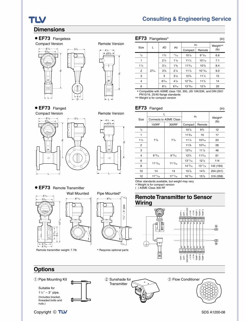
* Compatible with ASME class 150, 300, JIS 10K/20K, and DIN 2501 PN10/16, 25/40 flange standards** Weight is for compact version
① Pipe Mounting Kit
Suitable for 1a/B” – 3” pipe.(Includes bracket, threaded bolts and nuts.)
② Sunshade for Transmitter
③ Flow Conditioner
Compact Version
Compact Version¡EF73 Flanged
5g/H
5g/H
DL
L
H1
d
H1
¡EF73 Remote Transmitter
Remote Version
Remote Version
* Requires optional parts
Piping Installation
¡EF73 Flangeless
EF73 Flanged (in)
EF73 Flangeless* (in)
Dimensions
Remote Transmitter to Sensor Wiring
Piping InstallationOptions
Compact Remote
Connects to ASME Class
150RF 300RF Compact Remote
Other standards available, but weight may vary* Weight is for compact version( ) ASME Class 300 RF
6a/AF5i/AF
6a/AF5i/AF
4a/B
L
L
H1
H1
Wall Mounted
Remote transmitter weight: 7.7lb
3ae/AF4ac/AF
Pipe Mounted*
1a/B
” –
3” p
ipe
a/B
1
1a/B
2
3
4
6
2i/AF
1c/D
2a/B
3a/D
3e/H
5
6c/AF
8a/B
aa/AF
1a/H
1e/H
2a/H
3a/H
4a/H
6c/AF
10g/H
11a/D
11i/AF
11g/H
12c/H
12ae//AF
13ae//AF
6.6
7.1
8.4
9.0
12
14
20
a/B
1
1a/B
2
3
4
6
8
10
12
7g/H
9ac/AF
11ac/AF
14
17aa/AF
7g/H
9ac/AF
11ac/AF
14
17aa/AF
10g/H
11c//AF
11a/B
11c//D
12e/AF
12c/D
13aa/AF
14ac/AF
15g/H
16ac/AF
9c/D
10
10e/AF
10i/AF
11a/H
11i/AF
12a/B
13aa/AF
14c/D
15e/H
12
17
23
28
46
61
114
142 (164)
204 (241)
316 (358)
9aa//AF
10a/AF
10c/H
10aa//AF
11a/D
11c/D
12c/D
3
GN
GN
3
1
WT
WT
1
4
YL
YL
4
2
BN
BN
2
5
GY
GY
5
6
PK
PK
6
7
BU
BU
7
8
RD
RD
8
DIF
F +
DIF
F +
DIF
F –
DIF
F –
GR
OU
ND
GR
OU
ND
+ 5
VA
+ 5
VA
– 5
VA
– 5
VA
TE
MP
1T
EM
P 1
TE
MP
2T
EM
P 2
TE
MP
3T
EM
P 3
6a/AF
5i/AF
3ae/AF
5a/D
13aa/AF
4a/Bφ3c/H
8e/AF8aa/AF
φ3c/H
SDS A1200-08 Rev. 12/2009Specifications subject to change without notice.
¡EF73 Flangeless (Unit: lb/h)
¡EF73 Flanged (Unit: lb/h)
(Unit: Air: SCFM Water: GPM)
10203040506080100150200250300350400
10203040506080100150200250300350400
7.28.4 9.5 10.4 11.2 12.0 13.4 14.7 17.5 19.8 21.9 23.9 25.7 28.0
53.373.2 92.9 112 131 150 188 225 318 411 504 597 690 784
21.8 25.6 28.8 31.6 34.2 36.6 41.0 44.9 53.3 60.5 67.0 72.9 78.4 84.0
268 368 467 564 661 757 947 1136 1603 2069 2535 3002 3472 3946
62.5 73.2 82.5 90.7 98.1 105 118 129 153 174 192 209 225 240
659 906 1148 1388 1626 1861 2329 2792 3942 5087 6232 7381 8537 9701
105 123 138 152 164 175 196 215 255 290 321 349 375 400
1009 1510 1915 2315 2711 3104 3884 4657 6574 8483 10392 12309 14236 16178
234 274 309 340 367 393 440 481 572 649 719 782 841 897
2466 3390 4298 5195 6084 6966 8715 10450 14753 19036 23320 27620 31945 36302
405 475 535 588 636 681 761 833 990 1125 1245 1355 1457 1553
4271 5872 7446 9000 10540 12067 15097 18103 25556 32975 40396 47845 55336 62883
9211080 1216 1336 1446 1547 1731 1895 2252 2558 2831 3081 3313 3532
9717
13359
16939
20474
23976
27452
34344
41181
58136
75011
91894
108838
125880
143049
1767
2072
2333
2565
2776
2970
3322
3638
4322
4909
5433
5913
6359
6779
18654
25645
32517
39304
46026
52698
65929
79053
111601
143996
176404
208930
241645
274601
2786
3266
3678
4043
4375
4682
5236
5734
6813
7738
8565
9321
10024
10686
29404
40428
51260
61959
72556
83074
103932
124621
175928
226995
278085
329359
380930
432883
3995
4683
5275
5799
6274
6715
7511
8224
9772
11099
12285
13370
14378
15327
41930
57635
73135
88400
103450
118508
148117
177643
250844
323588
396732
469782
538924
620905
239 259 274 287 298 307 324 338 366 388 406 422 436 448
10.111.8 13.3 14.6 15.8 16.9 18.9 20.7 24.6 27.9 30.9 33.6 36.2 39.0
54.574.995.0114 134 153 192 230 326 420 515 610 706 1115
28.1 32.9 37.1 40.8 44.2 47.2 52.8 57.8 68.7 78.1 86.4 94.0 101 108
321442 560 677 793 907 1136 1362 1923 2481 3039 3600 4164 5091
75.9 88.9 101 111 120 128 143 157 186 211 234 254 274 292
760 1045 1324 1601 1875 2146 2685 3220 4545 5865 7186 8511 9844
11789
124145 163 179 194 207 232 254 302 342 379 412 443 473
1252 1721 2182 2638 3089 3537 4424 5305 7489 9664
11839 14023 16220 19129
277325366 402 435 466 521 571 678 770 852 927 997
1063
2756 3789 4805 5807 6801 7786 9741
11680 16489 21276 26067 30875 35712 43041
472554 623 685 742 794 888 972
1155 1311 1451 1580 1699 1811
4753 6535 8286
10015 11728 13428 16799 20143 28436 36692 44954 53246 61587 73333
1057 1239 1395 1534 1660 1776 1987 2175 2585 2936 3249 3536 3803 4054
10785 14828 18802 22726 26612 30470 38119 45706 64524 83258 102004 120820 139746 164214
239259 274 287 298 307 324 338 366 388 406 422 436 448
a/B
1
1a/B
2
3
4
6
8
10
12
2.5
7.1
18.3
29.5
66.6
113
252
–
–
–
20.6
94.7
220
356
803
1368
3066
–
–
–
0.9
1.9
4.9
7.9
17.8
30.3
67.8
–
–
–
30.3
83.6
193
317
717
1228
2752
–
–
–
1.8
5.3
15.3
25.4
56.0
96.6
220
421
664
952
14.1
73.5
180
301
677
1174
2670
5127
8038
11593
0.7
1.4
4.1
6.7
15.0
26.0
59.5
114
179
257
21.5
66.0
158
268
607
1052
2395
4601
7256
10409
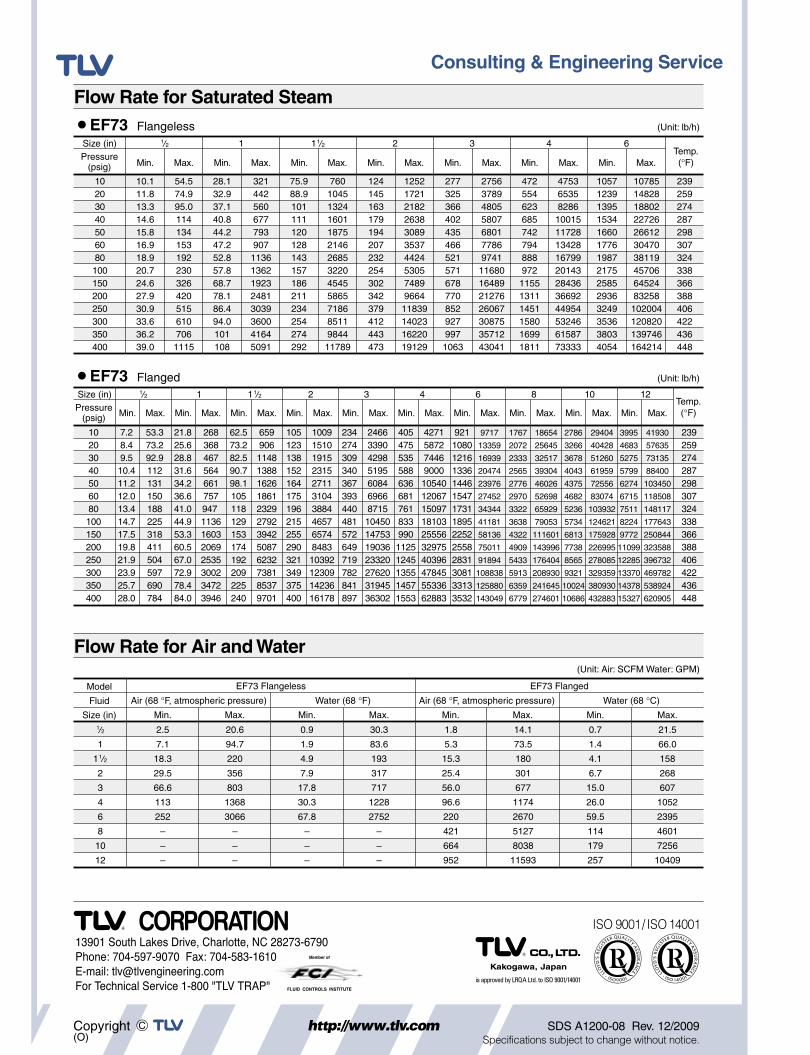
Flow Rate for Saturated Steam
Flow Rate for Air and Water
EF73 Flangeless EF73 Flanged
Fluid Air (68 °F, atmospheric pressure) Water (68 °F) Air (68 °F, atmospheric pressure) Water (68 °C)
Size (in)
Model
Min. Max. Min. Max. Min. Max. Min. Max.
Size (in) a/B
Min. Max. Min. Max. Min. Max. Min. Max. Min. Max. Min. Max. Min. Max.
1 1a/B 2 3 4 6Temp.(°F)
Temp.(°F)
Pressure(psig)
Size (in)Pressure
(psig)
a/B
Min. Max.
1
Min. Max.
1a/B
Min. Max.
2
Min. Max.
3
Min. Max.
4
Min. Max.
6
Min. Max.
8
Min. Max.
10
Min. Max.
12
Min. Max.