SD-PXE-AOU-H0004 4 Channels, 1 GSPS, Analog Output PXI ......The user HVI program is executed inside...
48
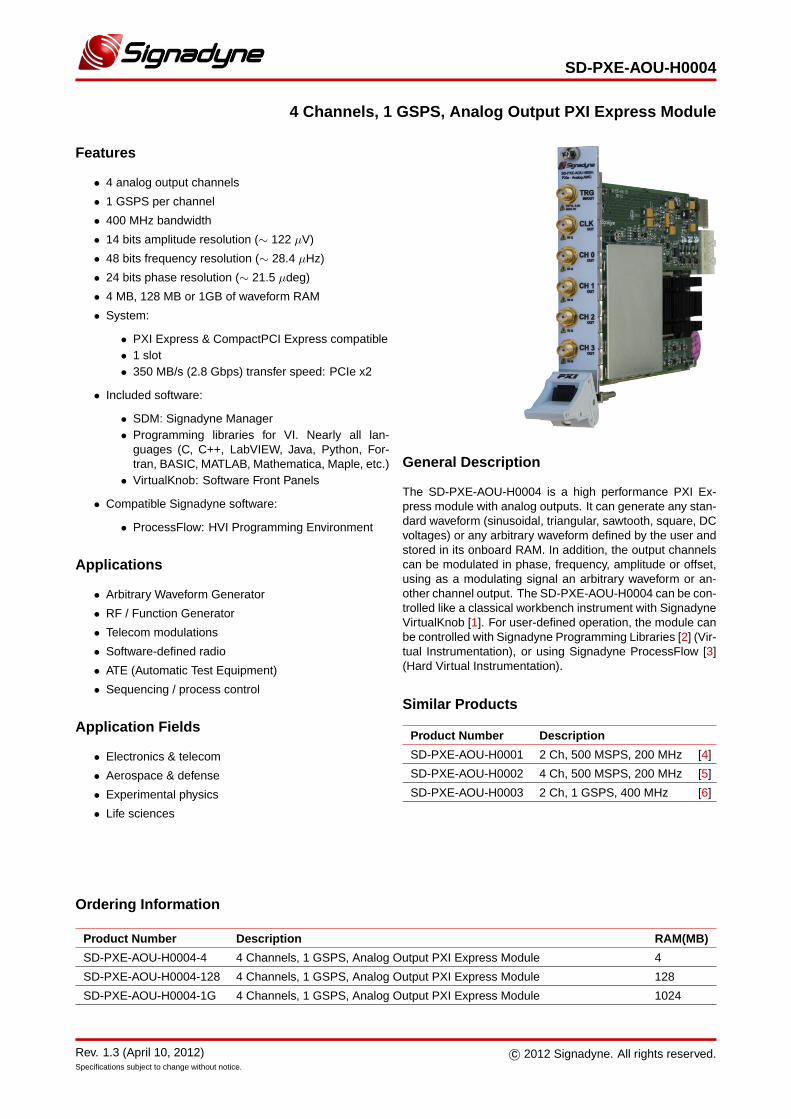
SD-PXE-AOU-H0004 4 Channels, 1 GSPS, Analog Output PXI Express Module Features • 4 analog output channels • 1 GSPS per channel • 400 MHz bandwidth • 14 bits amplitude resolution (∼ 122 μV) • 48 bits frequency resolution (∼ 28.4 μHz) • 24 bits phase resolution (∼ 21.5 μdeg) • 4 MB, 128 MB or 1GB of waveform RAM • System: • PXI Express & CompactPCI Express compatible • 1 slot • 350 MB/s (2.8 Gbps) transfer speed: PCIe x2 • Included software: • SDM: Signadyne Manager • Programming libraries for VI. Nearly all lan- guages (C, C++, LabVIEW, Java, Python, For- tran, BASIC, MATLAB, Mathematica, Maple, etc.) • VirtualKnob: Software Front Panels • Compatible Signadyne software: • ProcessFlow: HVI Programming Environment Applications • Arbitrary Waveform Generator • RF / Function Generator • Telecom modulations • Software-defined radio • ATE (Automatic Test Equipment) • Sequencing / process control Application Fields • Electronics & telecom • Aerospace & defense • Experimental physics • Life sciences General Description The SD-PXE-AOU-H0004 is a high performance PXI Ex- press module with analog outputs. It can generate any stan- dard waveform (sinusoidal, triangular, sawtooth, square, DC voltages) or any arbitrary waveform defined by the user and stored in its onboard RAM. In addition, the output channels can be modulated in phase, frequency, amplitude or offset, using as a modulating signal an arbitrary waveform or an- other channel output. The SD-PXE-AOU-H0004 can be con- trolled like a classical workbench instrument with Signadyne VirtualKnob [1]. For user-defined operation, the module can be controlled with Signadyne Programming Libraries [2] (Vir- tual Instrumentation), or using Signadyne ProcessFlow [3] (Hard Virtual Instrumentation). Similar Products Product Number Description SD-PXE-AOU-H0001 2 Ch, 500 MSPS, 200 MHz [4] SD-PXE-AOU-H0002 4 Ch, 500 MSPS, 200 MHz [5] SD-PXE-AOU-H0003 2 Ch, 1 GSPS, 400 MHz [6] Ordering Information Product Number Description RAM(MB) SD-PXE-AOU-H0004-4 4 Channels, 1 GSPS, Analog Output PXI Express Module 4 SD-PXE-AOU-H0004-128 4 Channels, 1 GSPS, Analog Output PXI Express Module 128 SD-PXE-AOU-H0004-1G 4 Channels, 1 GSPS, Analog Output PXI Express Module 1024 Rev. 1.3 (April 10, 2012) Specifications subject to change without notice. c 2012 Signadyne. All rights reserved.
Transcript of SD-PXE-AOU-H0004 4 Channels, 1 GSPS, Analog Output PXI ......The user HVI program is executed inside...
SD-PXE-AOU-H0004
4 Channels, 1 GSPS, Analog Output PXI Express Module
Features
• 4 analog output channels
• 1 GSPS per channel
• 400 MHz bandwidth
• 14 bits amplitude resolution (∼ 122 μV)
• 48 bits frequency resolution (∼ 28.4 μHz)
• 24 bits phase resolution (∼ 21.5 μdeg)
• 4 MB, 128 MB or 1GB of waveform RAM
• System:
• PXI Express & CompactPCI Express compatible• 1 slot• 350 MB/s (2.8 Gbps) transfer speed: PCIe x2
• Included software:
• SDM: Signadyne Manager• Programming libraries for VI. Nearly all lan-
guages (C, C++, LabVIEW, Java, Python, For-tran, BASIC, MATLAB, Mathematica, Maple, etc.)
• VirtualKnob: Software Front Panels
• Compatible Signadyne software:
• ProcessFlow: HVI Programming Environment
Applications
• Arbitrary Waveform Generator
• RF / Function Generator
• Telecom modulations
• Software-defined radio
• ATE (Automatic Test Equipment)
• Sequencing / process control
Application Fields
• Electronics & telecom
• Aerospace & defense
• Experimental physics
• Life sciences
General Description
The SD-PXE-AOU-H0004 is a high performance PXI Ex-press module with analog outputs. It can generate any stan-dard waveform (sinusoidal, triangular, sawtooth, square, DCvoltages) or any arbitrary waveform defined by the user andstored in its onboard RAM. In addition, the output channelscan be modulated in phase, frequency, amplitude or offset,using as a modulating signal an arbitrary waveform or an-other channel output. The SD-PXE-AOU-H0004 can be con-trolled like a classical workbench instrument with SignadyneVirtualKnob [1]. For user-defined operation, the module canbe controlled with Signadyne Programming Libraries [2] (Vir-tual Instrumentation), or using Signadyne ProcessFlow [3](Hard Virtual Instrumentation).
Similar Products
Product Number Description
SD-PXE-AOU-H0001 2 Ch, 500 MSPS, 200 MHz [4]
SD-PXE-AOU-H0002 4 Ch, 500 MSPS, 200 MHz [5]
SD-PXE-AOU-H0003 2 Ch, 1 GSPS, 400 MHz [6]
Ordering Information
Product Number Description RAM(MB)
SD-PXE-AOU-H0004-4 4 Channels, 1 GSPS, Analog Output PXI Express Module 4
SD-PXE-AOU-H0004-128 4 Channels, 1 GSPS, Analog Output PXI Express Module 128
SD-PXE-AOU-H0004-1G 4 Channels, 1 GSPS, Analog Output PXI Express Module 1024
Rev. 1.3 (April 10, 2012)Specifications subject to change without notice.
c© 2012 Signadyne. All rights reserved.
SD-PXE-AOU-H0004
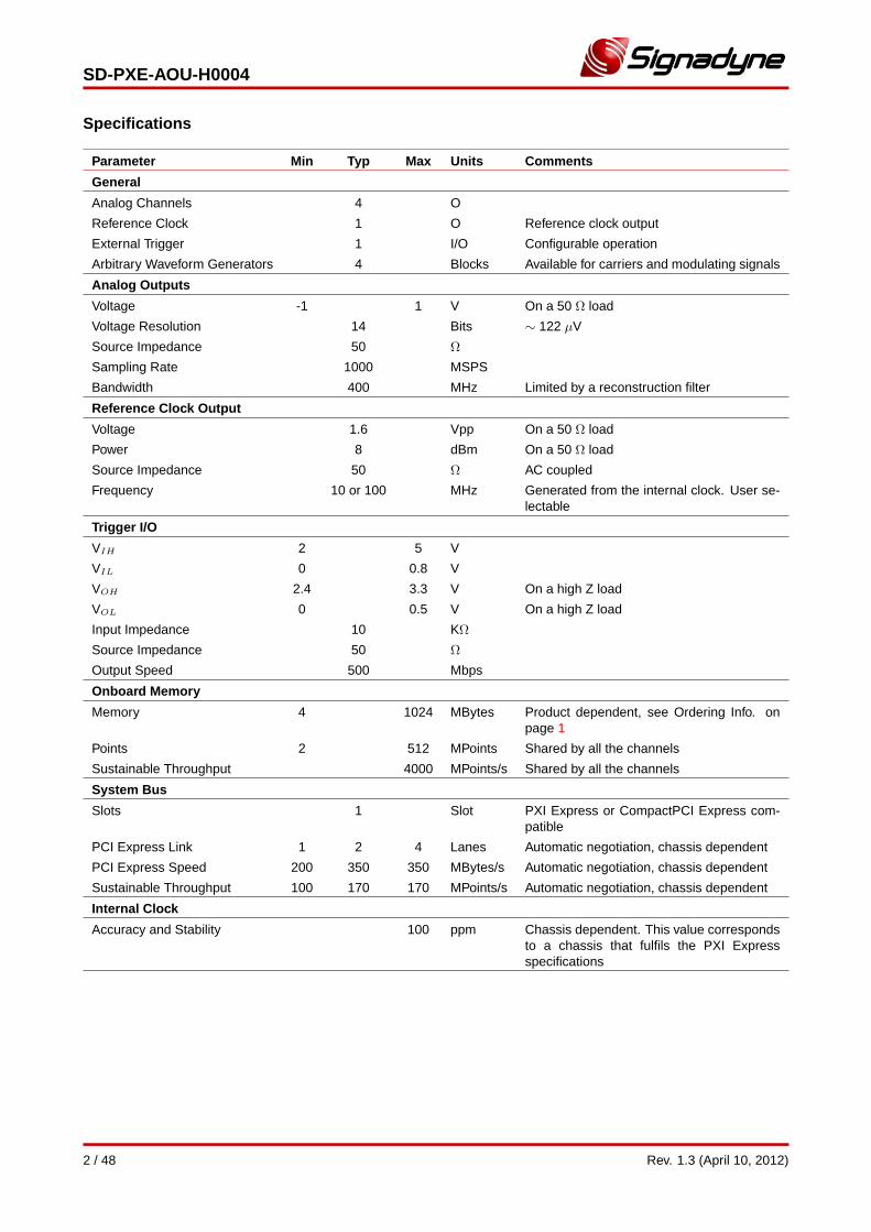
Specifications
Parameter Min Typ Max Units Comments
General
Analog Channels 4 O
Reference Clock 1 O Reference clock output
External Trigger 1 I/O Configurable operation
Arbitrary Waveform Generators 4 Blocks Available for carriers and modulating signals
Analog Outputs
Voltage -1 1 V On a 50 Ω load
Voltage Resolution 14 Bits ∼ 122 μV
Source Impedance 50 Ω
Sampling Rate 1000 MSPS
Bandwidth 400 MHz Limited by a reconstruction filter
Reference Clock Output
Voltage 1.6 Vpp On a 50 Ω load
Power 8 dBm On a 50 Ω load
Source Impedance 50 Ω AC coupled
Frequency 10 or 100 MHz Generated from the internal clock. User se-lectable
Trigger I/O
VIH 2 5 V
VIL 0 0.8 V
VOH 2.4 3.3 V On a high Z load
VOL 0 0.5 V On a high Z load
Input Impedance 10 KΩ
Source Impedance 50 Ω
Output Speed 500 Mbps
Onboard Memory
Memory 4 1024 MBytes Product dependent, see Ordering Info. onpage 1
Points 2 512 MPoints Shared by all the channels
Sustainable Throughput 4000 MPoints/s Shared by all the channels
System Bus
Slots 1 Slot PXI Express or CompactPCI Express com-patible
PCI Express Link 1 2 4 Lanes Automatic negotiation, chassis dependent
PCI Express Speed 200 350 350 MBytes/s Automatic negotiation, chassis dependent
Sustainable Throughput 100 170 170 MPoints/s Automatic negotiation, chassis dependent
Internal Clock
Accuracy and Stability 100 ppm Chassis dependent. This value correspondsto a chassis that fulfils the PXI Expressspecifications
2 / 48 Rev. 1.3 (April 10, 2012)
SD-PXE-AOU-H0004
Specifications
Parameter Min Typ Max Units Comments
AC Performance
Frequency Resolution 48 Bits ∼ 28.4 μHz
Phase Resolution 24 Bits ∼ 21.5 μdeg
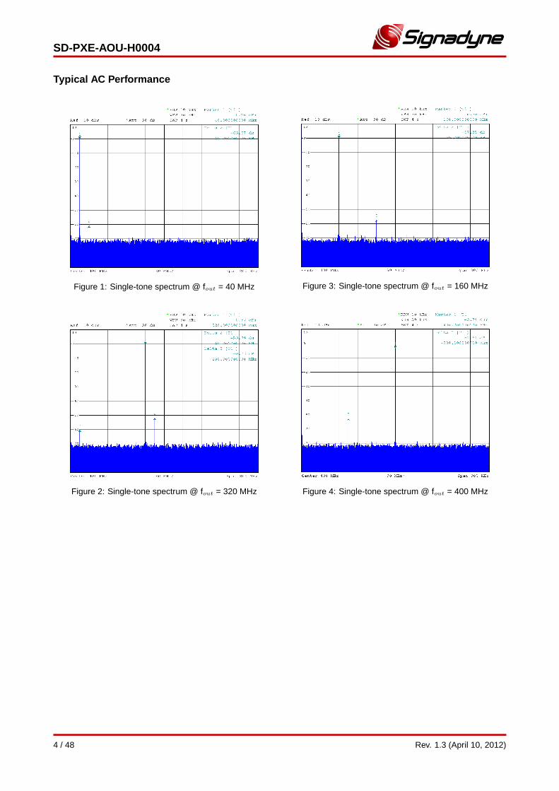
SFDR (Spurious-Free Dynamic Range) Pout = 0 dBm. Measured from DC to 1GHz
fout = 10 MHz 60 64 dBc
fout = 40 MHz 60 62 dBc
fout = 80 MHz 61 63 dBc
fout = 120 MHz 58 61 dBc
fout = 160 MHz 54 57 dBc
fout = 200 MHz 52 55 dBc
fout = 320 MHz 50 53 dBc
fout = 400 MHz 50 52 dBc
Crosstalk (Adjacent Channels)
fout = 10 MHz <-105 -105 dB
fout = 40 MHz -85 -82 dB
fout = 80 MHz -80 -77 dB
fout = 120 MHz -89 -86 dB
fout = 160 MHz -76 -73 dB
fout = 200 MHz -86 -83 dB
fout = 320 MHz -83 -80 dB
fout = 400 MHz -81 -78 dB
Crosstalk (Non-adjacent Channels)
fout = 10 MHz <-105 -105 dB
fout = 40 MHz -89 -86 dB
fout = 80 MHz -81 -78 dB
fout = 120 MHz -103 -100 dB
fout = 160 MHz -95 -92 dB
fout = 200 MHz -102 -99 dB
fout = 320 MHz -97 -94 dB
fout = 400 MHz -95 -92 dB
Average Noise Density -144 -140 dBm/Hz
Rev. 1.3 (April 10, 2012) 3 / 48
SD-PXE-AOU-H0004
Typical AC Performance
Figure 1: Single-tone spectrum @ fout = 40 MHz
Figure 2: Single-tone spectrum @ fout = 320 MHz
Figure 3: Single-tone spectrum @ fout = 160 MHz
Figure 4: Single-tone spectrum @ fout = 400 MHz
4 / 48 Rev. 1.3 (April 10, 2012)
SD-PXE-AOU-H0004
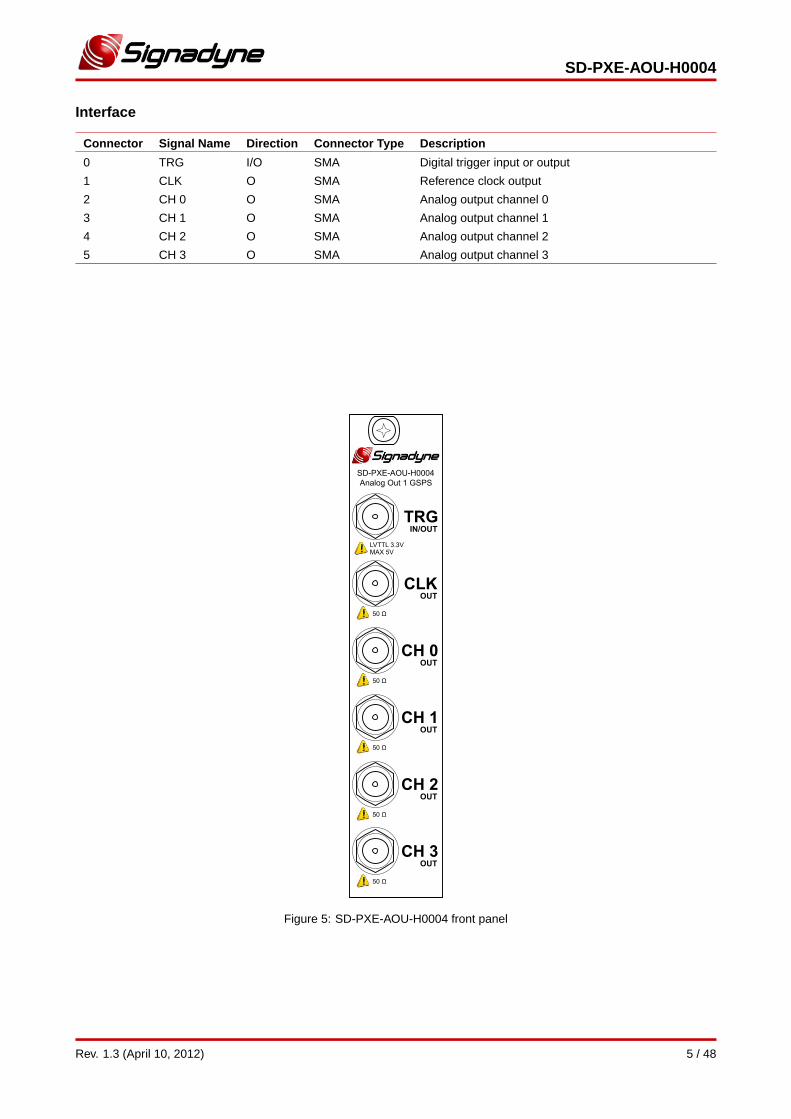
Interface
Connector Signal Name Direction Connector Type Description
0 TRG I/O SMA Digital trigger input or output
1 CLK O SMA Reference clock output
2 CH 0 O SMA Analog output channel 0
3 CH 1 O SMA Analog output channel 1
4 CH 2 O SMA Analog output channel 2
5 CH 3 O SMA Analog output channel 3
Figure 5: SD-PXE-AOU-H0004 front panel
Rev. 1.3 (April 10, 2012) 5 / 48
SD-PXE-AOU-H0004
4 Channels, 1 GSPS, Analog Output PXI Express Module
Contents
1 Device Operation 71.1 Overview . . . . . . . . . . . . . . . . . . . . . . . . . . . . . . . . . . . . . . . . . . . . . . . . . . . . . . 7
1.1.1 Classical Instrument . . . . . . . . . . . . . . . . . . . . . . . . . . . . . . . . . . . . . . . . . . . . 71.1.2 Virtual Instrument (VI) . . . . . . . . . . . . . . . . . . . . . . . . . . . . . . . . . . . . . . . . . . . 71.1.3 Hard Virtual Instrument (HVI) . . . . . . . . . . . . . . . . . . . . . . . . . . . . . . . . . . . . . . . 7
1.2 Waveform Generator . . . . . . . . . . . . . . . . . . . . . . . . . . . . . . . . . . . . . . . . . . . . . . . . 91.2.1 Wave Selector . . . . . . . . . . . . . . . . . . . . . . . . . . . . . . . . . . . . . . . . . . . . . . . . 91.2.2 Frequency / Phase Control . . . . . . . . . . . . . . . . . . . . . . . . . . . . . . . . . . . . . . . . . 101.2.3 Amplitude / Offset Control . . . . . . . . . . . . . . . . . . . . . . . . . . . . . . . . . . . . . . . . . 111.2.4 Partner Channel Connection . . . . . . . . . . . . . . . . . . . . . . . . . . . . . . . . . . . . . . . . 12
1.3 Clock and Trigger . . . . . . . . . . . . . . . . . . . . . . . . . . . . . . . . . . . . . . . . . . . . . . . . . . 131.3.1 Clock System . . . . . . . . . . . . . . . . . . . . . . . . . . . . . . . . . . . . . . . . . . . . . . . . 131.3.2 Trigger I/O . . . . . . . . . . . . . . . . . . . . . . . . . . . . . . . . . . . . . . . . . . . . . . . . . . 13
1.4 Arbitrary Waveform Generators (AWGs) . . . . . . . . . . . . . . . . . . . . . . . . . . . . . . . . . . . . . 14
2 VI / HVI Programming 172.1 Overview . . . . . . . . . . . . . . . . . . . . . . . . . . . . . . . . . . . . . . . . . . . . . . . . . . . . . . 172.2 SD-AOU Class Functions . . . . . . . . . . . . . . . . . . . . . . . . . . . . . . . . . . . . . . . . . . . . . 18
2.2.1 ChannelWaveShape . . . . . . . . . . . . . . . . . . . . . . . . . . . . . . . . . . . . . . . . . . . . 182.2.2 ChannelFrequency . . . . . . . . . . . . . . . . . . . . . . . . . . . . . . . . . . . . . . . . . . . . . 192.2.3 ChannelPhase . . . . . . . . . . . . . . . . . . . . . . . . . . . . . . . . . . . . . . . . . . . . . . . 202.2.4 ChannelPhaseReset . . . . . . . . . . . . . . . . . . . . . . . . . . . . . . . . . . . . . . . . . . . . 212.2.5 ChannelAmplitude . . . . . . . . . . . . . . . . . . . . . . . . . . . . . . . . . . . . . . . . . . . . . 222.2.6 ChannelOffset . . . . . . . . . . . . . . . . . . . . . . . . . . . . . . . . . . . . . . . . . . . . . . . . 232.2.7 ModulationFreqPhaseConfig . . . . . . . . . . . . . . . . . . . . . . . . . . . . . . . . . . . . . . . . 242.2.8 ModulationAmpOffsetConfig . . . . . . . . . . . . . . . . . . . . . . . . . . . . . . . . . . . . . . . . 252.2.9 ClockConfig . . . . . . . . . . . . . . . . . . . . . . . . . . . . . . . . . . . . . . . . . . . . . . . . . 262.2.10 TriggerConfig . . . . . . . . . . . . . . . . . . . . . . . . . . . . . . . . . . . . . . . . . . . . . . . . 272.2.11 TriggerWrite . . . . . . . . . . . . . . . . . . . . . . . . . . . . . . . . . . . . . . . . . . . . . . . . . 282.2.12 TriggerRead . . . . . . . . . . . . . . . . . . . . . . . . . . . . . . . . . . . . . . . . . . . . . . . . . 292.2.13 WaveformLoad . . . . . . . . . . . . . . . . . . . . . . . . . . . . . . . . . . . . . . . . . . . . . . . 302.2.14 WaveformFlush . . . . . . . . . . . . . . . . . . . . . . . . . . . . . . . . . . . . . . . . . . . . . . . 312.2.15 AWG . . . . . . . . . . . . . . . . . . . . . . . . . . . . . . . . . . . . . . . . . . . . . . . . . . . . . 322.2.16 AWGqueueWaveform . . . . . . . . . . . . . . . . . . . . . . . . . . . . . . . . . . . . . . . . . . . . 342.2.17 AWGflush . . . . . . . . . . . . . . . . . . . . . . . . . . . . . . . . . . . . . . . . . . . . . . . . . . 352.2.18 AWGrun . . . . . . . . . . . . . . . . . . . . . . . . . . . . . . . . . . . . . . . . . . . . . . . . . . . 362.2.19 AWGstop . . . . . . . . . . . . . . . . . . . . . . . . . . . . . . . . . . . . . . . . . . . . . . . . . . 372.2.20 AWGtrigger . . . . . . . . . . . . . . . . . . . . . . . . . . . . . . . . . . . . . . . . . . . . . . . . . 382.2.21 MathAssign (D=S) . . . . . . . . . . . . . . . . . . . . . . . . . . . . . . . . . . . . . . . . . . . . . 392.2.22 MathArithmetics (R=A[+-*/]B) . . . . . . . . . . . . . . . . . . . . . . . . . . . . . . . . . . . . . . . 402.2.23 MathMultAcc (R=A[+-]B[*/]C) . . . . . . . . . . . . . . . . . . . . . . . . . . . . . . . . . . . . . . . . 412.2.24 Open . . . . . . . . . . . . . . . . . . . . . . . . . . . . . . . . . . . . . . . . . . . . . . . . . . . . . 422.2.25 Close . . . . . . . . . . . . . . . . . . . . . . . . . . . . . . . . . . . . . . . . . . . . . . . . . . . . 43
2.3 SD-Wave Class Functions . . . . . . . . . . . . . . . . . . . . . . . . . . . . . . . . . . . . . . . . . . . . . 442.3.1 New . . . . . . . . . . . . . . . . . . . . . . . . . . . . . . . . . . . . . . . . . . . . . . . . . . . . . 442.3.2 Delete . . . . . . . . . . . . . . . . . . . . . . . . . . . . . . . . . . . . . . . . . . . . . . . . . . . . 45
2.4 Error Codes . . . . . . . . . . . . . . . . . . . . . . . . . . . . . . . . . . . . . . . . . . . . . . . . . . . . . 46
6 / 48 Rev. 1.3 (April 10, 2012)
SD-PXE-AOU-H0004
1 Device Operation
1.1 Overview
1.1.1 Classical Instrument
Any Signadyne module can be used as a classical workbench instrument using Signadyne VirtualKnob [1], our ready-to-use software front panels. They are designed to control the inputs and outputs of the modules in real time, making themideal for standard test and measurement applications.
1.1.2 Virtual Instrument (VI)
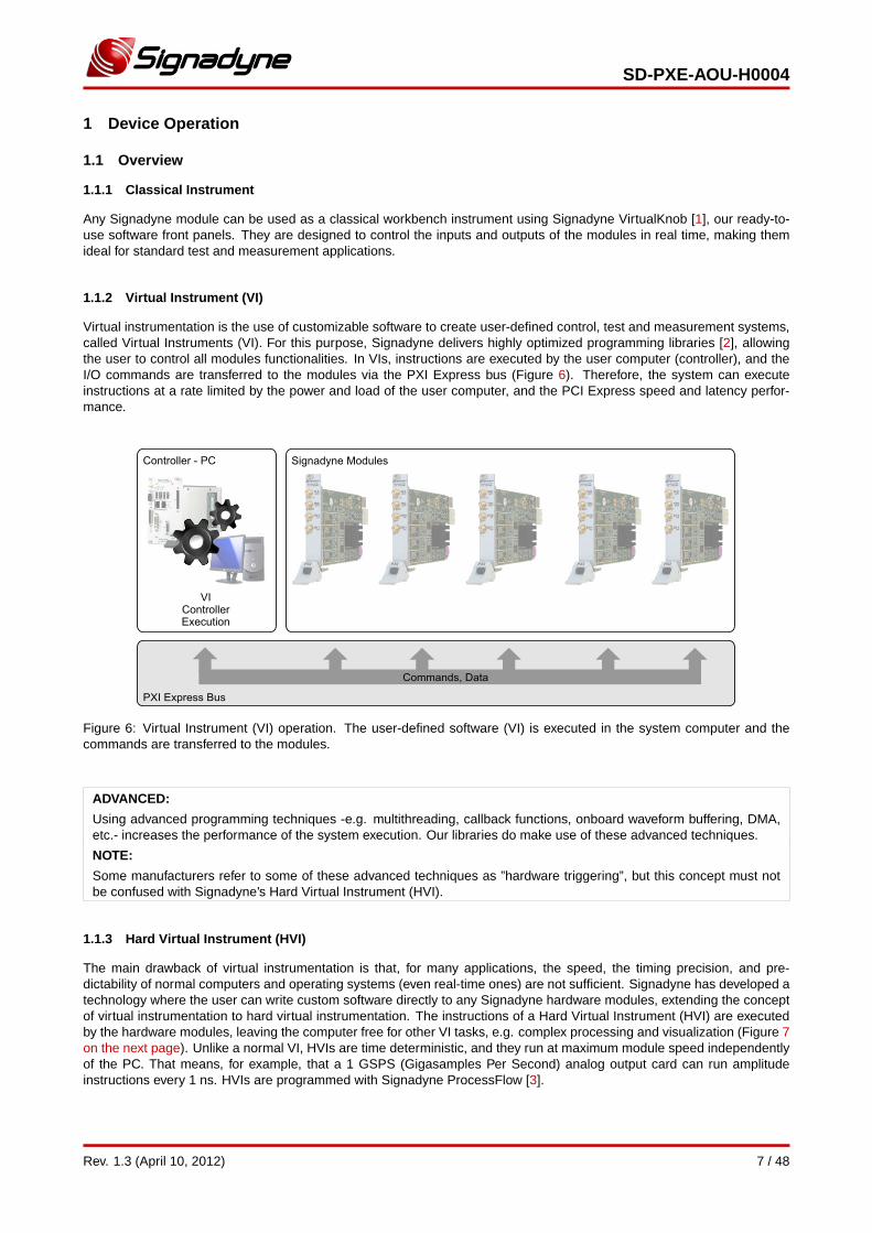
Virtual instrumentation is the use of customizable software to create user-defined control, test and measurement systems,called Virtual Instruments (VI). For this purpose, Signadyne delivers highly optimized programming libraries [2], allowingthe user to control all modules functionalities. In VIs, instructions are executed by the user computer (controller), and theI/O commands are transferred to the modules via the PXI Express bus (Figure 6). Therefore, the system can executeinstructions at a rate limited by the power and load of the user computer, and the PCI Express speed and latency perfor-mance.
Figure 6: Virtual Instrument (VI) operation. The user-defined software (VI) is executed in the system computer and thecommands are transferred to the modules.
ADVANCED:
Using advanced programming techniques -e.g. multithreading, callback functions, onboard waveform buffering, DMA,etc.- increases the performance of the system execution. Our libraries do make use of these advanced techniques.
NOTE:
Some manufacturers refer to some of these advanced techniques as ”hardware triggering”, but this concept must notbe confused with Signadyne’s Hard Virtual Instrument (HVI).
1.1.3 Hard Virtual Instrument (HVI)
The main drawback of virtual instrumentation is that, for many applications, the speed, the timing precision, and pre-dictability of normal computers and operating systems (even real-time ones) are not sufficient. Signadyne has developed atechnology where the user can write custom software directly to any Signadyne hardware modules, extending the conceptof virtual instrumentation to hard virtual instrumentation. The instructions of a Hard Virtual Instrument (HVI) are executedby the hardware modules, leaving the computer free for other VI tasks, e.g. complex processing and visualization (Figure 7on the next page). Unlike a normal VI, HVIs are time deterministic, and they run at maximum module speed independentlyof the PC. That means, for example, that a 1 GSPS (Gigasamples Per Second) analog output card can run amplitudeinstructions every 1 ns. HVIs are programmed with Signadyne ProcessFlow [3].
Rev. 1.3 (April 10, 2012) 7 / 48
SD-PXE-AOU-H0004
NOTE:
HVIs are programmed with Signadyne ProcessFlow [3], an HVI programming environment with a user-friendly flowchart-style interface, compatible with all Signadyne hardware modules.
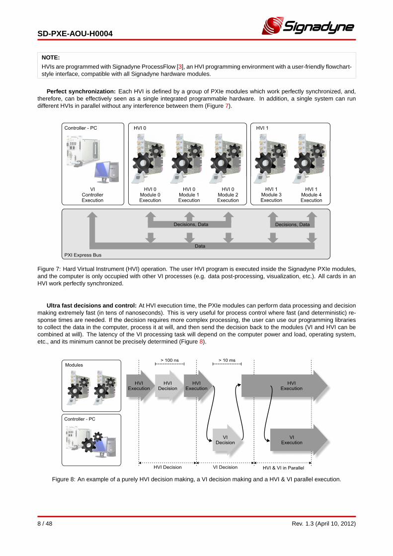
Perfect synchronization: Each HVI is defined by a group of PXIe modules which work perfectly synchronized, and,therefore, can be effectively seen as a single integrated programmable hardware. In addition, a single system can rundifferent HVIs in parallel without any interference between them (Figure 7).
Figure 7: Hard Virtual Instrument (HVI) operation. The user HVI program is executed inside the Signadyne PXIe modules,and the computer is only occupied with other VI processes (e.g. data post-processing, visualization, etc.). All cards in anHVI work perfectly synchronized.
Ultra fast decisions and control: At HVI execution time, the PXIe modules can perform data processing and decisionmaking extremely fast (in tens of nanoseconds). This is very useful for process control where fast (and deterministic) re-sponse times are needed. If the decision requires more complex processing, the user can use our programming librariesto collect the data in the computer, process it at will, and then send the decision back to the modules (VI and HVI can becombined at will). The latency of the VI processing task will depend on the computer power and load, operating system,etc., and its minimum cannot be precisely determined (Figure 8).
Figure 8: An example of a purely HVI decision making, a VI decision making and a HVI & VI parallel execution.
8 / 48 Rev. 1.3 (April 10, 2012)
SD-PXE-AOU-H0004
1.2 Waveform Generator
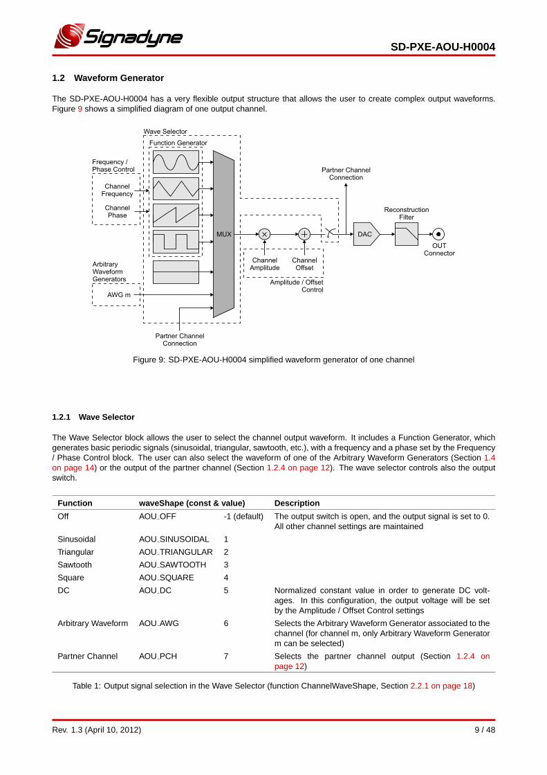
The SD-PXE-AOU-H0004 has a very flexible output structure that allows the user to create complex output waveforms.Figure 9 shows a simplified diagram of one output channel.
Figure 9: SD-PXE-AOU-H0004 simplified waveform generator of one channel
1.2.1 Wave Selector
The Wave Selector block allows the user to select the channel output waveform. It includes a Function Generator, whichgenerates basic periodic signals (sinusoidal, triangular, sawtooth, etc.), with a frequency and a phase set by the Frequency/ Phase Control block. The user can also select the waveform of one of the Arbitrary Waveform Generators (Section 1.4on page 14) or the output of the partner channel (Section 1.2.4 on page 12). The wave selector controls also the outputswitch.
Function waveShape (const & value) Description
Off AOU OFF -1 (default) The output switch is open, and the output signal is set to 0.All other channel settings are maintained
Sinusoidal AOU SINUSOIDAL 1
Triangular AOU TRIANGULAR 2
Sawtooth AOU SAWTOOTH 3
Square AOU SQUARE 4
DC AOU DC 5 Normalized constant value in order to generate DC volt-ages. In this configuration, the output voltage will be setby the Amplitude / Offset Control settings
Arbitrary Waveform AOU AWG 6 Selects the Arbitrary Waveform Generator associated to thechannel (for channel m, only Arbitrary Waveform Generatorm can be selected)
Partner Channel AOU PCH 7 Selects the partner channel output (Section 1.2.4 onpage 12)
Table 1: Output signal selection in the Wave Selector (function ChannelWaveShape, Section 2.2.1 on page 18)
Rev. 1.3 (April 10, 2012) 9 / 48
SD-PXE-AOU-H0004
NOTE:
Waveform harmonics: Non-sinusoidal wave shapes (triangular, sawtooth, square, etc.) have high frequency compo-nents that may fall outside the bandwidth of the reconstruction filter if the fundamental frequency is too high. In thissituation, the output analog signal may suffer some distortion due to the missing harmonics, becoming a sinusoidal asthe fundamental frequency approaches the cutoff frequency of the filter.
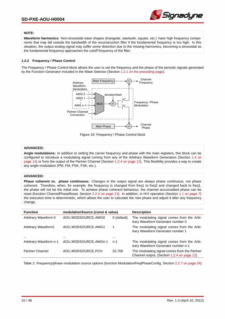
1.2.2 Frequency / Phase Control
The Frequency / Phase Control block allows the user to set the frequency and the phase of the periodic signals generatedby the Function Generator included in the Wave Selector (Section 1.2.1 on the preceding page).
Figure 10: Frequency / Phase Control block
ADVANCED:
Angle modulations: In addition to setting the carrier frequency and phase with the main registers, this block can beconfigured to introduce a modulating signal coming from any of the Arbitrary Waveform Generators (Section 1.4 onpage 14) or from the output of the Partner Channel (Section 1.2.4 on page 12). This flexibility provides a way to createany angle modulation (PM, FM, PSK, FSK, etc.).
ADVANCED:
Phase coherent vs. phase continuous: Changes in the output signal are always phase continuous, not phasecoherent. Therefore, when, for example, the frequency is changed from freq1 to freq2 and changed back to freq1,the phase will not be the initial one. To achieve phase coherent behaviour, the channel accumulated phase can bereset (function ChannelPhaseReset, Section 2.2.4 on page 21). In addition, in HVI operation (Section 1.1 on page 7)the execution time is deterministic, which allows the user to calculate the new phase and adjust it after any frequencychange.
Function modulationSource (const & value) Description
Arbitrary Waveform 0 AOU MODSOURCE AWG0 0 (default) The modulating signal comes from the Arbi-trary Waveform Generator number 0
Arbitrary Waveform1 AOU MODSOURCE AWG1 1 The modulating signal comes from the Arbi-trary Waveform Generator number 1
... ... ...
Arbitrary Waveform n-1 AOU MODSOURCE AWGn-1 n-1 The modulating signal comes from the Arbi-trary Waveform Generator number n-1
Partner Channel AOU MODSOURCE PCH 32,768 The modulating signal comes from the PartnerChannel output, (Section 1.2.4 on page 12)
Table 2: Frequency/phase modulation source options (function ModulationFreqPhaseConfig, Section 2.2.7 on page 24)
10 / 48 Rev. 1.3 (April 10, 2012)
SD-PXE-AOU-H0004
Function modulationType (const & value) Description
No Modulation AOU MOD OFF 0 (default) Modulation is disabled. The channel frequency andphase are only set by the main registers
Frequency Modulation AOU MOD FM 1 The modulating signal is used to modulate the channelfrequency
Phase Modulation AOU MOD PHASE 2 The modulating signal is used to modulate the channelphase
Table 3: Frequency/phase modulation options (function ModulationFreqPhaseConfig, Section 2.2.7 on page 24)
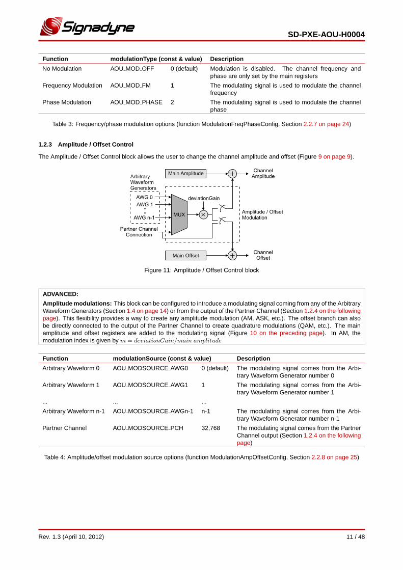
1.2.3 Amplitude / Offset Control
The Amplitude / Offset Control block allows the user to change the channel amplitude and offset (Figure 9 on page 9).
Figure 11: Amplitude / Offset Control block
ADVANCED:
Amplitude modulations: This block can be configured to introduce a modulating signal coming from any of the ArbitraryWaveform Generators (Section 1.4 on page 14) or from the output of the Partner Channel (Section 1.2.4 on the followingpage). This flexibility provides a way to create any amplitude modulation (AM, ASK, etc.). The offset branch can alsobe directly connected to the output of the Partner Channel to create quadrature modulations (QAM, etc.). The mainamplitude and offset registers are added to the modulating signal (Figure 10 on the preceding page). In AM, themodulation index is given by m = deviationGain/main amplitude
Function modulationSource (const & value) Description
Arbitrary Waveform 0 AOU MODSOURCE AWG0 0 (default) The modulating signal comes from the Arbi-trary Waveform Generator number 0
Arbitrary Waveform 1 AOU MODSOURCE AWG1 1 The modulating signal comes from the Arbi-trary Waveform Generator number 1
... ... ...
Arbitrary Waveform n-1 AOU MODSOURCE AWGn-1 n-1 The modulating signal comes from the Arbi-trary Waveform Generator number n-1
Partner Channel AOU MODSOURCE PCH 32,768 The modulating signal comes from the PartnerChannel output (Section 1.2.4 on the followingpage)
Table 4: Amplitude/offset modulation source options (function ModulationAmpOffsetConfig, Section 2.2.8 on page 25)
Rev. 1.3 (April 10, 2012) 11 / 48
SD-PXE-AOU-H0004
Function modulationType (const & value) Description
No Modulation AOU MOD OFF 0 (default) Modulation is disabled. The channel amplitudeand offset are only set by the main registers
Amplitude Modula-tion
AOU MOD AM 1 The modulating signal is used to modulate thechannel amplitude
Offset Modulation AOU MOD OFFSET 2 The modulating signal is used to modulate thechannel offset
Amplitude & OffsetModulation
AOU MOD AMOFFSET 3 The modulating signal is used to modulate both,the channel amplitude and offset
Amplitude Modula-tion & Offset PartnerChannel
AOU MOD AMOFFSETPCH 4 The modulation signal is used to modulate thechannel amplitude while the Partner Channelmodulates the offset (Section 1.2.4)
Table 5: Amplitude/offset modulation options (function ModulationAmpOffsetConfig, Section 2.2.8 on page 25)
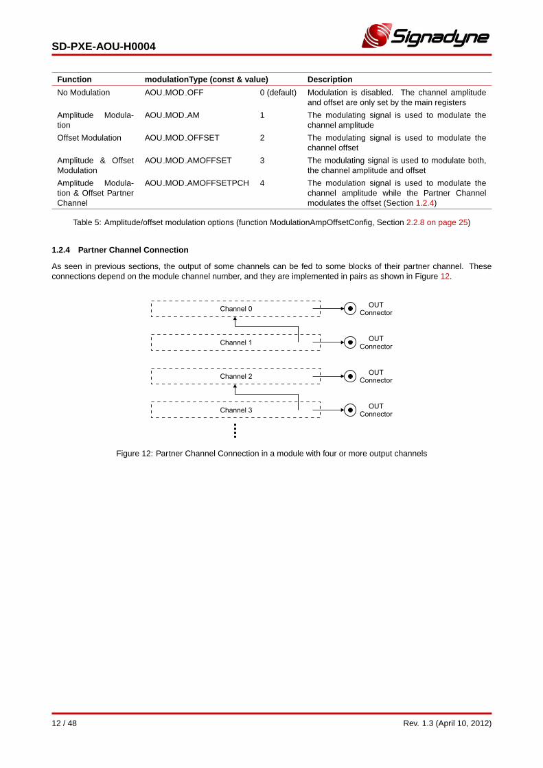
1.2.4 Partner Channel Connection
As seen in previous sections, the output of some channels can be fed to some blocks of their partner channel. Theseconnections depend on the module channel number, and they are implemented in pairs as shown in Figure 12.
Figure 12: Partner Channel Connection in a module with four or more output channels
12 / 48 Rev. 1.3 (April 10, 2012)
SD-PXE-AOU-H0004
1.3 Clock and Trigger
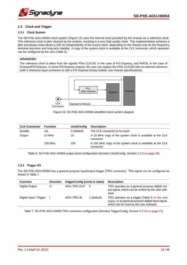
1.3.1 Clock System
The SD-PXE-AOU-H0004 clock system (Figure 13) uses the internal clock provided by the chassis as a reference clock.This reference clock is jitter cleaned by the module, resulting in a very high quality clock. This implementation achieves ajitter and phase noise above a 100 Hz independently of the source clock, depending on the chassis only for the frequencyabsolute precision and long term stability. A copy of the system clock is available at the CLK connector, which operationcan be configured by the user (Table 6).
ADVANCED:
The reference clock is taken from the signals PXIe CLK100, in the case of PXI Express, and RefClk, in the case ofCompactPCI Express. In some PXI Express chassis, the user can replace the PXIe CLK100 with an external reference(with a reference input connector or with a PXI Express timing module, see chassis specifications).
Figure 13: SD-PXE-AOU-H0004 simplified clock system diagram
CLK Connector Function clockConfig Description
Disable n/a 0 (default) The CLK connector is not used
Output 10 MHz 10 A 10 MHz copy of the system clock is available at the CLKconnector
100 MHz 100 A 100 MHz copy of the system clock is available at the CLKconnector
Table 6: SD-PXE-AOU-H0004 output clock configuration (function ClockConfig, Section 2.2.9 on page 26)
1.3.2 Trigger I/O
The SD-PXE-AOU-H0004 has a general purpose input/output trigger (TRG connector). This signal can be configured asshown in Table 7.
Function Direction triggerConfig (const & value) Description
Digital Output O AOU TRG OUT 0 TRG operates as a general purpose digital out-put signal, which can be written by the user soft-ware
Digital Input / Trigger I AOU TRG IN 1 (default) TRG operates as a trigger (Table 8 on the nextpage), or as general purpose digital input signal,which can be read by the user software
Table 7: SD-PXE-AOU-H0004 TRG connector configuration (function TriggerConfig, Section 2.2.10 on page 27)
Rev. 1.3 (April 10, 2012) 13 / 48
SD-PXE-AOU-H0004
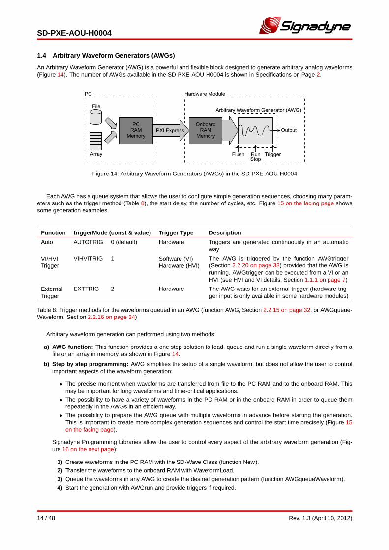
1.4 Arbitrary Waveform Generators (AWGs)
An Arbitrary Waveform Generator (AWG) is a powerful and flexible block designed to generate arbitrary analog waveforms(Figure 14). The number of AWGs available in the SD-PXE-AOU-H0004 is shown in Specifications on Page 2.
Figure 14: Arbitrary Waveform Generators (AWGs) in the SD-PXE-AOU-H0004
Each AWG has a queue system that allows the user to configure simple generation sequences, choosing many param-eters such as the trigger method (Table 8), the start delay, the number of cycles, etc. Figure 15 on the facing page showssome generation examples.
Function triggerMode (const & value) Trigger Type Description
Auto AUTOTRIG 0 (default) Hardware Triggers are generated continuously in an automaticway
VI/HVITrigger
VIHVITRIG 1 Software (VI)Hardware (HVI)
The AWG is triggered by the function AWGtrigger(Section 2.2.20 on page 38) provided that the AWG isrunning. AWGtrigger can be executed from a VI or anHVI (see HVI and VI details, Section 1.1.1 on page 7)
ExternalTrigger
EXTTRIG 2 Hardware The AWG waits for an external trigger (hardware trig-ger input is only available in some hardware modules)
Table 8: Trigger methods for the waveforms queued in an AWG (function AWG, Section 2.2.15 on page 32, or AWGqueue-Waveform, Section 2.2.16 on page 34)
Arbitrary waveform generation can performed using two methods:
a) AWG function: This function provides a one step solution to load, queue and run a single waveform directly from afile or an array in memory, as shown in Figure 14.
b) Step by step programming: AWG simplifies the setup of a single waveform, but does not allow the user to controlimportant aspects of the waveform generation:
• The precise moment when waveforms are transferred from file to the PC RAM and to the onboard RAM. Thismay be important for long waveforms and time-critical applications.
• The possibility to have a variety of waveforms in the PC RAM or in the onboard RAM in order to queue themrepeatedly in the AWGs in an efficient way.
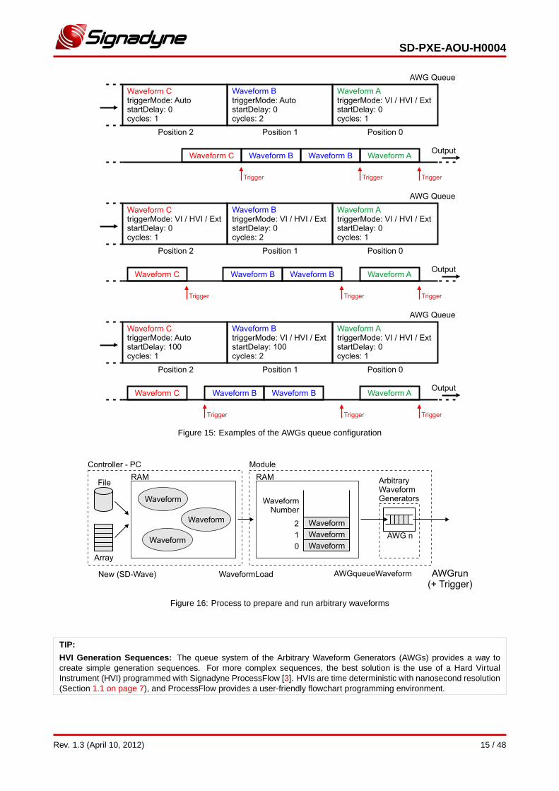
• The possibility to prepare the AWG queue with multiple waveforms in advance before starting the generation.This is important to create more complex generation sequences and control the start time precisely (Figure 15on the facing page).
Signadyne Programming Libraries allow the user to control every aspect of the arbitrary waveform generation (Fig-ure 16 on the next page):
1) Create waveforms in the PC RAM with the SD-Wave Class (function New).
2) Transfer the waveforms to the onboard RAM with WaveformLoad.
3) Queue the waveforms in any AWG to create the desired generation pattern (function AWGqueueWaveform).
4) Start the generation with AWGrun and provide triggers if required.
14 / 48 Rev. 1.3 (April 10, 2012)
SD-PXE-AOU-H0004
Figure 15: Examples of the AWGs queue configuration
Figure 16: Process to prepare and run arbitrary waveforms
TIP:
HVI Generation Sequences: The queue system of the Arbitrary Waveform Generators (AWGs) provides a way tocreate simple generation sequences. For more complex sequences, the best solution is the use of a Hard VirtualInstrument (HVI) programmed with Signadyne ProcessFlow [3]. HVIs are time deterministic with nanosecond resolution(Section 1.1 on page 7), and ProcessFlow provides a user-friendly flowchart programming environment.
Rev. 1.3 (April 10, 2012) 15 / 48

SD-PXE-AOU-H0004
TIP:
Pausing and Resuming an AWG: The function AWGstop pauses the AWG operation, leaving the last waveform pointat the output. The waveform generation can be resumed calling AWGrun.
Note: After a call to AWG, the selected AWG is running, because this function performs an AWGrun automatically.
Prescaler: Each queued waveform can have a sampling clock prescaler associated with it. This prescaler divides theeffective waveform sampling rate providing a way to reduce waveform sizes.
ADVANCED:
Prescaler and aliasing: Note that reducing the effective sampling rate produces aliasing inside the module reconstruc-tion filter bandwidth. This unfiltered alias appears in the output.
16 / 48 Rev. 1.3 (April 10, 2012)
SD-PXE-AOU-H0004
2 VI / HVI Programming
2.1 Overview
As described in Section 1.1.2 on page 7, virtual instrumentation is the use of customizable software to create user-definedcontrol, test and measurement systems, called Virtual Instruments (VI). For this purpose, Signadyne delivers highly opti-mized static and dynamic programming libraries [2].
a) Static Libraries
Ready-to-use static libraries are supplied for the following programming languages and compilers:
Language Compiler Files
C Any C compiler *.h, *.lib
MinGW (Qt), GCC *.h, *.a
C++ Microsoft Visual Studio *.h, *.lib
MinGW (Qt), GCC *.h, *.a
LabVIEW National Instruments LabVIEW *.vi
b) Dynamic Libraries
Dynamic libraries are compatible with any programming language that has a compiler capable of performing dynamiclinking. Here are some examples:
∙ C++ compilers not listed above.
∙ Other programming languages: Java, Python, Visual Basic, C#, PHP, Perl, Fortran, Pascal, etc.
∙ Computer Algebra Systems (CAS): MathWorks MATLAB, Wolfram Mathematica, Maplesoft Maple, etc.
Dynamic libraries available:
Exported Functions Language Operating System Files
C Microsoft Windows *.dll
NOTE:
DLL function prototypes: The exported functions of the dynamic libraries have the same prototype as their counter-parts of the static libraries.
NOTE:
Function Parameters: Some of the parameters of the library functions are language dependent. The table of inputs andoutputs parameters for each function is a conceptual description, therefore, the user must check the specific languagefunction to see how to use it. One example are the ID parameters (moduleID, etc.), which identify objects in non object-oriented languages. In object-oriented languages the objects are identified by their instances, and therefore the ID arenot present.
Function Names: Some programming languages like C++ or LabVIEW have a feature called function overloadingor polymorphism, that allows creating several functions with the same name but different input/output parameters. Inlanguages without this feature, functions with different parameters must have different names.
Rev. 1.3 (April 10, 2012) 17 / 48
SD-PXE-AOU-H0004
2.2 SD-AOU Class Functions
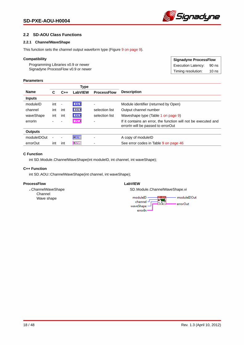
2.2.1 ChannelWaveShape
This function sets the channel output waveform type (Figure 9 on page 9).
Compatibility
Programming Libraries v0.9 or newerSignadyne ProcessFlow v0.9 or newer
Signadyne ProcessFlow
Execution Latency: 90 ns
Timing resolution: 10 ns
Parameters
NameType
DescriptionC C++ LabVIEW ProcessFlow
Inputs
moduleID int - - Module identifier (returned by Open)
channel int int selection list Output channel number
waveShape int int selection list Waveshape type (Table 1 on page 9)
errorIn - - - If it contains an error, the function will not be executed anderrorIn will be passed to errorOut
Outputs
moduleIDOut - - - A copy of moduleID
errorOut int int - See error codes in Table 9 on page 46
C Function
int SD Module ChannelWaveShape(int moduleID, int channel, int waveShape);
C++ Function
int SD AOU::ChannelWaveShape(int channel, int waveShape);
ProcessFlow
ChannelWaveShapeChannelWave shape
LabVIEW
SD Module ChannelWaveShape.vi
18 / 48 Rev. 1.3 (April 10, 2012)
SD-PXE-AOU-H0004
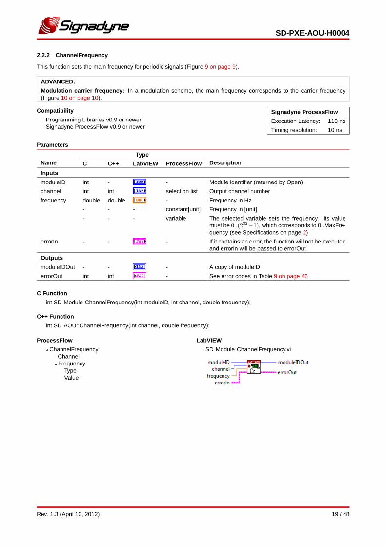
2.2.2 ChannelFrequency
This function sets the main frequency for periodic signals (Figure 9 on page 9).
ADVANCED:
Modulation carrier frequency: In a modulation scheme, the main frequency corresponds to the carrier frequency(Figure 10 on page 10).
Compatibility
Programming Libraries v0.9 or newerSignadyne ProcessFlow v0.9 or newer
Signadyne ProcessFlow
Execution Latency: 110 ns
Timing resolution: 10 ns
Parameters
NameType
DescriptionC C++ LabVIEW ProcessFlow
Inputs
moduleID int - - Module identifier (returned by Open)
channel int int selection list Output channel number
frequency double double - Frequency in Hz
- - - constant[unit] Frequency in [unit]
- - - variable The selected variable sets the frequency. Its valuemust be 0..(232−1), which corresponds to 0..MaxFre-quency (see Specifications on page 2)
errorIn - - - If it contains an error, the function will not be executedand errorIn will be passed to errorOut
Outputs
moduleIDOut - - - A copy of moduleID
errorOut int int - See error codes in Table 9 on page 46
C Function
int SD Module ChannelFrequency(int moduleID, int channel, double frequency);
C++ Function
int SD AOU::ChannelFrequency(int channel, double frequency);
ProcessFlow
ChannelFrequencyChannelFrequency
TypeValue
LabVIEW
SD Module ChannelFrequency.vi
Rev. 1.3 (April 10, 2012) 19 / 48
SD-PXE-AOU-H0004
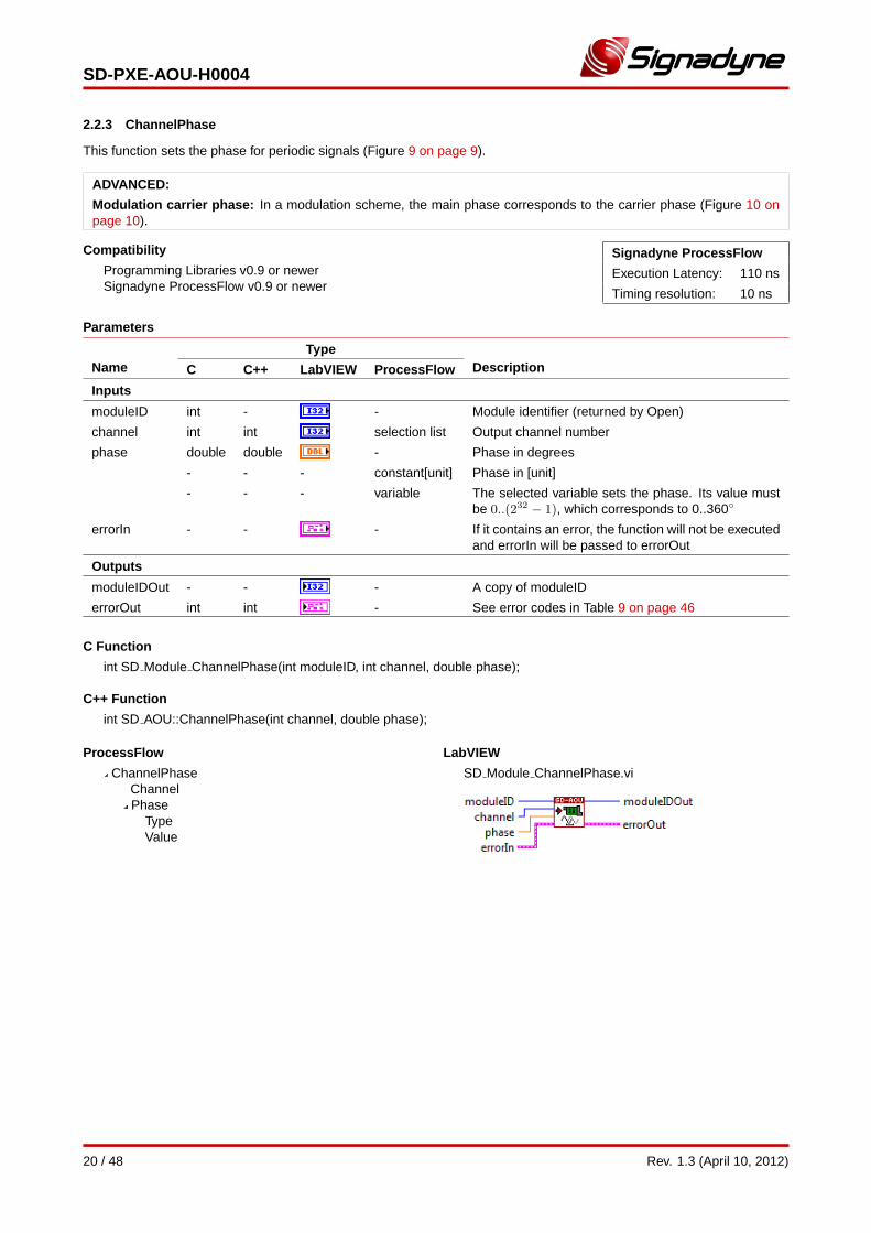
2.2.3 ChannelPhase
This function sets the phase for periodic signals (Figure 9 on page 9).
ADVANCED:
Modulation carrier phase: In a modulation scheme, the main phase corresponds to the carrier phase (Figure 10 onpage 10).
Compatibility
Programming Libraries v0.9 or newerSignadyne ProcessFlow v0.9 or newer
Signadyne ProcessFlow
Execution Latency: 110 ns
Timing resolution: 10 ns
Parameters
NameType
DescriptionC C++ LabVIEW ProcessFlow
Inputs
moduleID int - - Module identifier (returned by Open)
channel int int selection list Output channel number
phase double double - Phase in degrees
- - - constant[unit] Phase in [unit]
- - - variable The selected variable sets the phase. Its value mustbe 0..(232 − 1), which corresponds to 0..360◦
errorIn - - - If it contains an error, the function will not be executedand errorIn will be passed to errorOut
Outputs
moduleIDOut - - - A copy of moduleID
errorOut int int - See error codes in Table 9 on page 46
C Function
int SD Module ChannelPhase(int moduleID, int channel, double phase);
C++ Function
int SD AOU::ChannelPhase(int channel, double phase);
ProcessFlow
ChannelPhaseChannelPhase
TypeValue
LabVIEW
SD Module ChannelPhase.vi
20 / 48 Rev. 1.3 (April 10, 2012)
SD-PXE-AOU-H0004
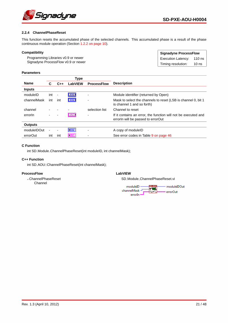
2.2.4 ChannelPhaseReset
This function resets the accumulated phase of the selected channels. This accumulated phase is a result of the phasecontinuous module operation (Section 1.2.2 on page 10).
Compatibility
Programming Libraries v0.9 or newerSignadyne ProcessFlow v0.9 or newer
Signadyne ProcessFlow
Execution Latency: 110 ns
Timing resolution: 10 ns
Parameters
NameType
DescriptionC C++ LabVIEW ProcessFlow
Inputs
moduleID int - - Module identifier (returned by Open)
channelMask int int - Mask to select the channels to reset (LSB is channel 0, bit 1is channel 1 and so forth)
channel - - - selection list Channel to reset
errorIn - - - If it contains an error, the function will not be executed anderrorIn will be passed to errorOut
Outputs
moduleIDOut - - - A copy of moduleID
errorOut int int - See error codes in Table 9 on page 46
C Function
int SD Module ChannelPhaseReset(int moduleID, int channelMask);
C++ Function
int SD AOU::ChannelPhaseReset(int channelMask);
ProcessFlow
ChannelPhaseResetChannel
LabVIEW
SD Module ChannelPhaseReset.vi
Rev. 1.3 (April 10, 2012) 21 / 48

SD-PXE-AOU-H0004
2.2.5 ChannelAmplitude
This function sets the amplitude of a channel output signal (Figure 9 on page 9).
ADVANCED:
Modulation index: In a modulation scheme, this amplitude value is added as an offset to the modulating signal (Fig-ure 10 on page 10). In AM, the modulation index is given by m = deviationGain/amplitude.
Compatibility
Programming Libraries v0.9 or newerSignadyne ProcessFlow v0.9 or newer
Signadyne ProcessFlow
Execution Latency: 60 ns
Timing resolution: 1 ns ns
Parameters
NameType
DescriptionC C++ LabVIEW ProcessFlow
Inputs
moduleID int - - Module identifier (returned by Open)
channel int int selection list Output channel number
amplitude double double - Amplitude in volts
- - - constant[unit] Amplitude in [unit]
- - - variable The selected variable sets the amplitude. Its valuemust be −(215 − 1)..(215 − 1), which corresponds to−MaxAmplitude..MaxAmplitude (see Specificationson page 2)
errorIn - - - If it contains an error, the function will not be executedand errorIn will be passed to errorOut
Outputs
moduleIDOut - - - A copy of moduleID
errorOut int int - See error codes in Table 9 on page 46
C Function
int SD Module ChannelAmplitude(int moduleID, int channel, double amplitude);
C++ Function
int SD AOU::ChannelAmplitude(int channel, double amplitude);
ProcessFlow
ChannelAmplitudeChannelAmplitude
TypeValue
LabVIEW
SD Module ChannelAmplitude.vi
22 / 48 Rev. 1.3 (April 10, 2012)
SD-PXE-AOU-H0004
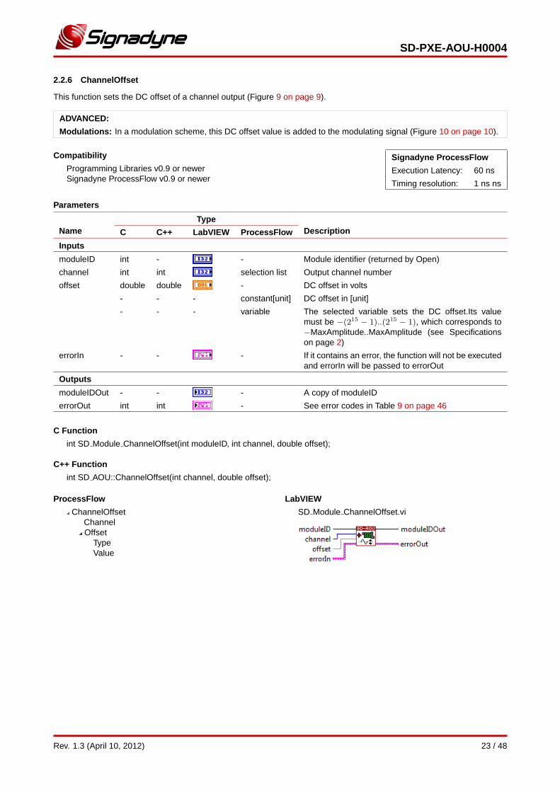
2.2.6 ChannelOffset
This function sets the DC offset of a channel output (Figure 9 on page 9).
ADVANCED:
Modulations: In a modulation scheme, this DC offset value is added to the modulating signal (Figure 10 on page 10).
Compatibility
Programming Libraries v0.9 or newerSignadyne ProcessFlow v0.9 or newer
Signadyne ProcessFlow
Execution Latency: 60 ns
Timing resolution: 1 ns ns
Parameters
NameType
DescriptionC C++ LabVIEW ProcessFlow
Inputs
moduleID int - - Module identifier (returned by Open)
channel int int selection list Output channel number
offset double double - DC offset in volts
- - - constant[unit] DC offset in [unit]
- - - variable The selected variable sets the DC offset.Its valuemust be −(215 − 1)..(215 − 1), which corresponds to−MaxAmplitude..MaxAmplitude (see Specificationson page 2)
errorIn - - - If it contains an error, the function will not be executedand errorIn will be passed to errorOut
Outputs
moduleIDOut - - - A copy of moduleID
errorOut int int - See error codes in Table 9 on page 46
C Function
int SD Module ChannelOffset(int moduleID, int channel, double offset);
C++ Function
int SD AOU::ChannelOffset(int channel, double offset);
ProcessFlow
ChannelOffsetChannelOffset
TypeValue
LabVIEW
SD Module ChannelOffset.vi
Rev. 1.3 (April 10, 2012) 23 / 48
SD-PXE-AOU-H0004
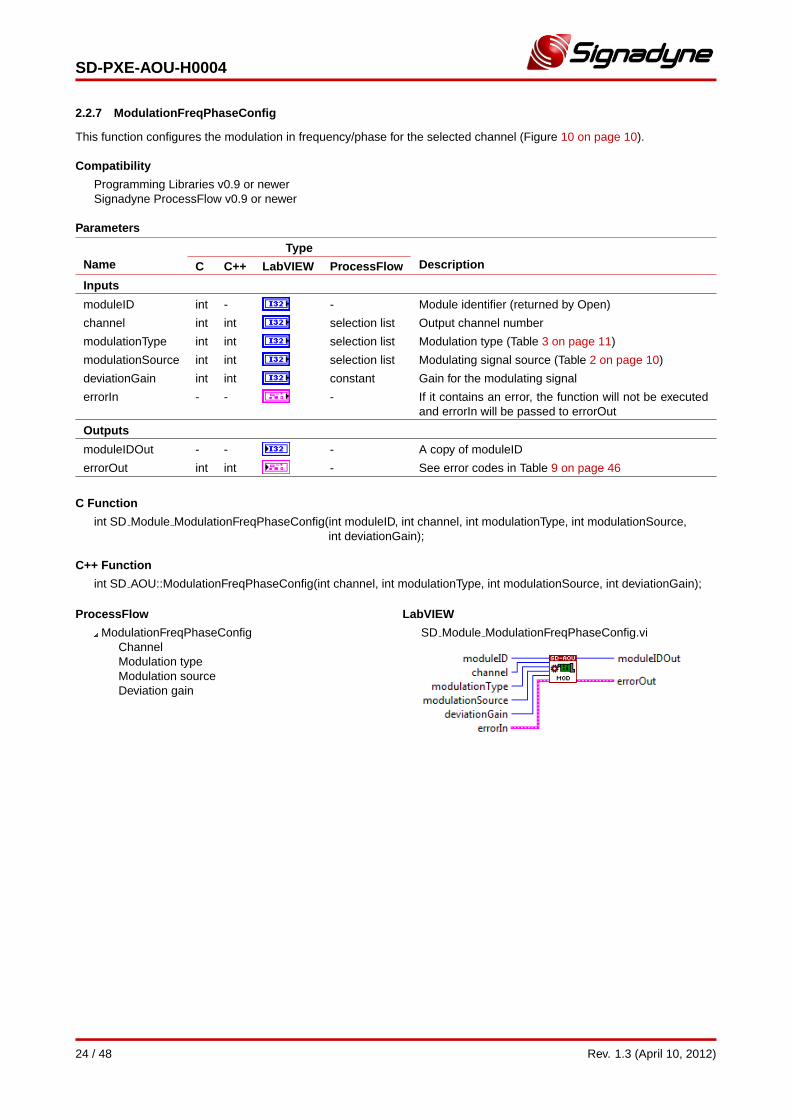
2.2.7 ModulationFreqPhaseConfig
This function configures the modulation in frequency/phase for the selected channel (Figure 10 on page 10).
Compatibility
Programming Libraries v0.9 or newerSignadyne ProcessFlow v0.9 or newer
Parameters
NameType
DescriptionC C++ LabVIEW ProcessFlow
Inputs
moduleID int - - Module identifier (returned by Open)
channel int int selection list Output channel number
modulationType int int selection list Modulation type (Table 3 on page 11)
modulationSource int int selection list Modulating signal source (Table 2 on page 10)
deviationGain int int constant Gain for the modulating signal
errorIn - - - If it contains an error, the function will not be executedand errorIn will be passed to errorOut
Outputs
moduleIDOut - - - A copy of moduleID
errorOut int int - See error codes in Table 9 on page 46
C Function
int SD Module ModulationFreqPhaseConfig(int moduleID, int channel, int modulationType, int modulationSource,int deviationGain);
C++ Function
int SD AOU::ModulationFreqPhaseConfig(int channel, int modulationType, int modulationSource, int deviationGain);
ProcessFlow
ModulationFreqPhaseConfigChannelModulation typeModulation sourceDeviation gain
LabVIEW
SD Module ModulationFreqPhaseConfig.vi
24 / 48 Rev. 1.3 (April 10, 2012)
SD-PXE-AOU-H0004
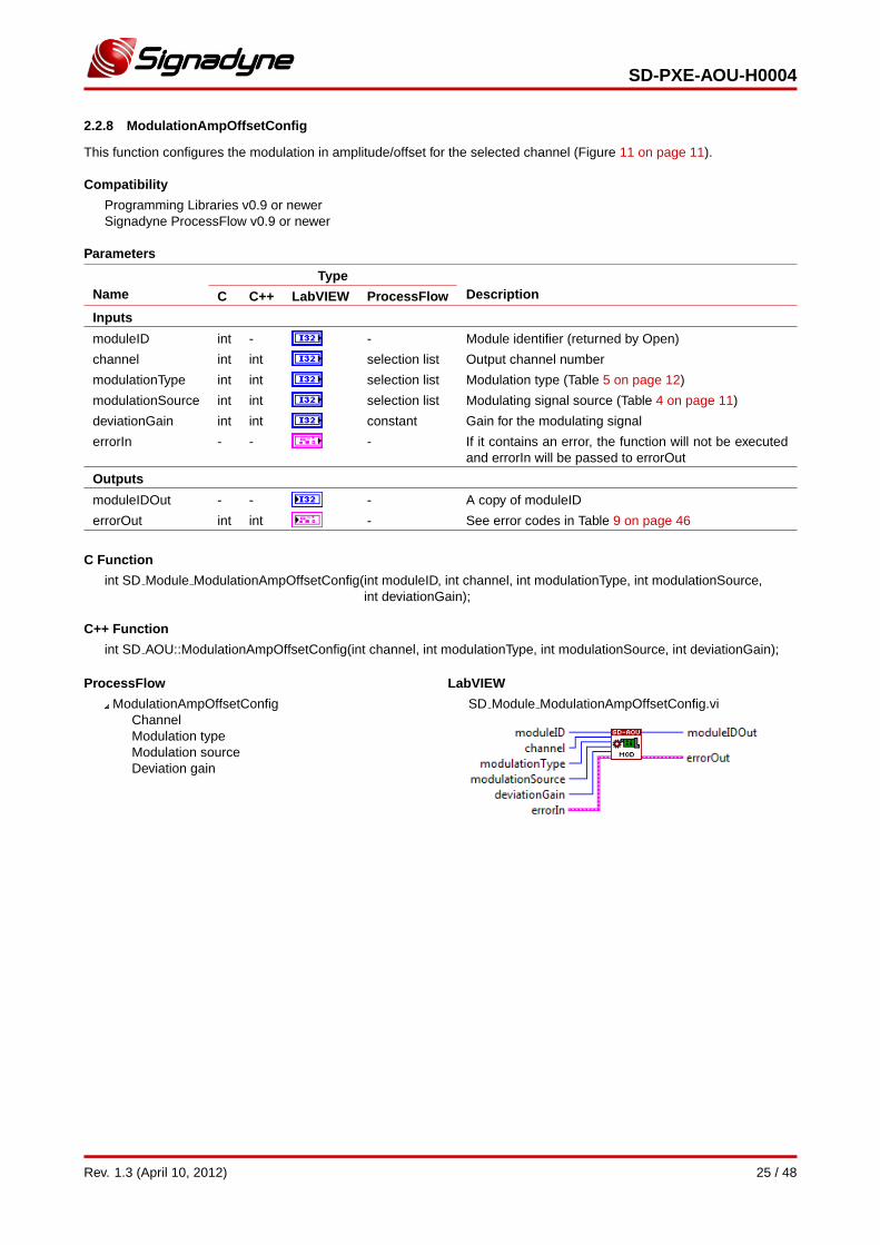
2.2.8 ModulationAmpOffsetConfig
This function configures the modulation in amplitude/offset for the selected channel (Figure 11 on page 11).
Compatibility
Programming Libraries v0.9 or newerSignadyne ProcessFlow v0.9 or newer
Parameters
NameType
DescriptionC C++ LabVIEW ProcessFlow
Inputs
moduleID int - - Module identifier (returned by Open)
channel int int selection list Output channel number
modulationType int int selection list Modulation type (Table 5 on page 12)
modulationSource int int selection list Modulating signal source (Table 4 on page 11)
deviationGain int int constant Gain for the modulating signal
errorIn - - - If it contains an error, the function will not be executedand errorIn will be passed to errorOut
Outputs
moduleIDOut - - - A copy of moduleID
errorOut int int - See error codes in Table 9 on page 46
C Function
int SD Module ModulationAmpOffsetConfig(int moduleID, int channel, int modulationType, int modulationSource,int deviationGain);
C++ Function
int SD AOU::ModulationAmpOffsetConfig(int channel, int modulationType, int modulationSource, int deviationGain);
ProcessFlow
ModulationAmpOffsetConfigChannelModulation typeModulation sourceDeviation gain
LabVIEW
SD Module ModulationAmpOffsetConfig.vi
Rev. 1.3 (April 10, 2012) 25 / 48
SD-PXE-AOU-H0004
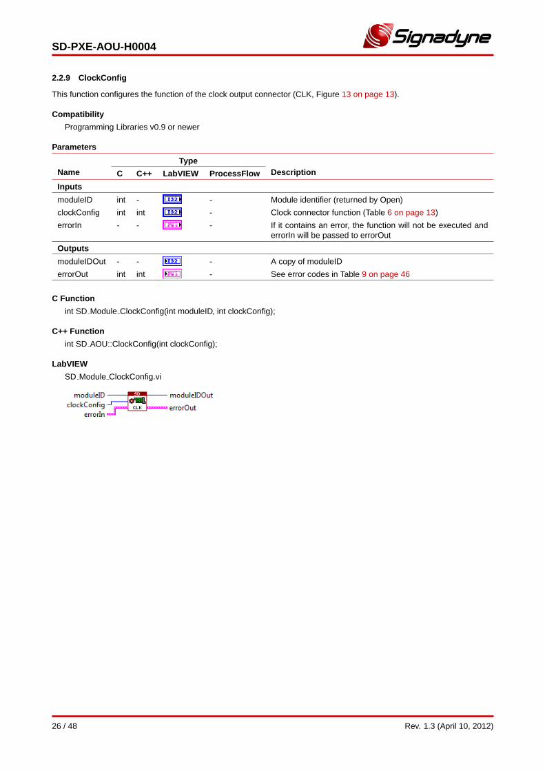
2.2.9 ClockConfig
This function configures the function of the clock output connector (CLK, Figure 13 on page 13).
Compatibility
Programming Libraries v0.9 or newer
Parameters
NameType
DescriptionC C++ LabVIEW ProcessFlow
Inputs
moduleID int - - Module identifier (returned by Open)
clockConfig int int - Clock connector function (Table 6 on page 13)
errorIn - - - If it contains an error, the function will not be executed anderrorIn will be passed to errorOut
Outputs
moduleIDOut - - - A copy of moduleID
errorOut int int - See error codes in Table 9 on page 46
C Function
int SD Module ClockConfig(int moduleID, int clockConfig);
C++ Function
int SD AOU::ClockConfig(int clockConfig);
LabVIEW
SD Module ClockConfig.vi
26 / 48 Rev. 1.3 (April 10, 2012)
SD-PXE-AOU-H0004
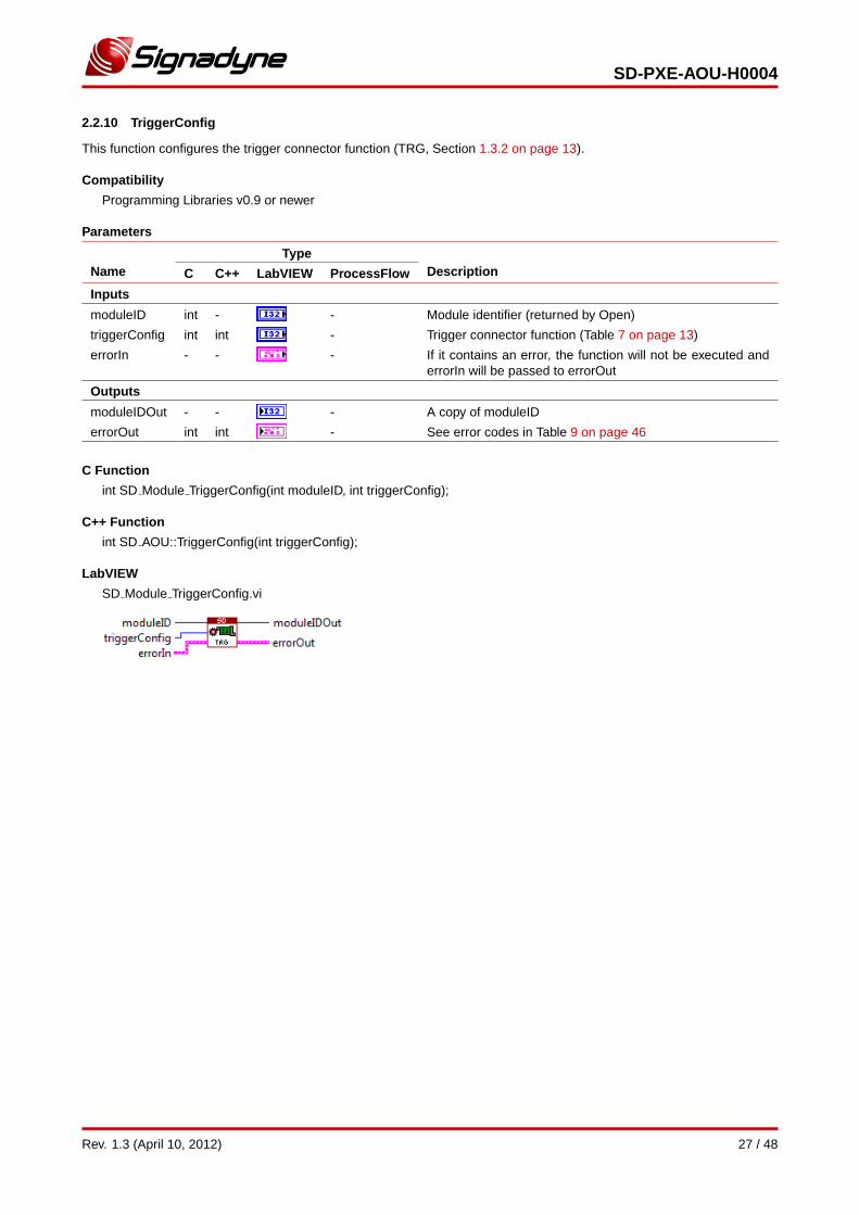
2.2.10 TriggerConfig
This function configures the trigger connector function (TRG, Section 1.3.2 on page 13).
Compatibility
Programming Libraries v0.9 or newer
Parameters
NameType
DescriptionC C++ LabVIEW ProcessFlow
Inputs
moduleID int - - Module identifier (returned by Open)
triggerConfig int int - Trigger connector function (Table 7 on page 13)
errorIn - - - If it contains an error, the function will not be executed anderrorIn will be passed to errorOut
Outputs
moduleIDOut - - - A copy of moduleID
errorOut int int - See error codes in Table 9 on page 46
C Function
int SD Module TriggerConfig(int moduleID, int triggerConfig);
C++ Function
int SD AOU::TriggerConfig(int triggerConfig);
LabVIEW
SD Module TriggerConfig.vi
Rev. 1.3 (April 10, 2012) 27 / 48
SD-PXE-AOU-H0004
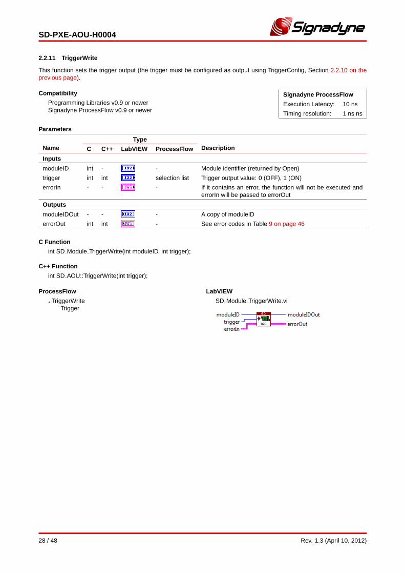
2.2.11 TriggerWrite
This function sets the trigger output (the trigger must be configured as output using TriggerConfig, Section 2.2.10 on theprevious page).
Compatibility
Programming Libraries v0.9 or newerSignadyne ProcessFlow v0.9 or newer
Signadyne ProcessFlow
Execution Latency: 10 ns
Timing resolution: 1 ns ns
Parameters
NameType
DescriptionC C++ LabVIEW ProcessFlow
Inputs
moduleID int - - Module identifier (returned by Open)
trigger int int selection list Trigger output value: 0 (OFF), 1 (ON)
errorIn - - - If it contains an error, the function will not be executed anderrorIn will be passed to errorOut
Outputs
moduleIDOut - - - A copy of moduleID
errorOut int int - See error codes in Table 9 on page 46
C Function
int SD Module TriggerWrite(int moduleID, int trigger);
C++ Function
int SD AOU::TriggerWrite(int trigger);
ProcessFlow
TriggerWriteTrigger
LabVIEW
SD Module TriggerWrite.vi
28 / 48 Rev. 1.3 (April 10, 2012)
SD-PXE-AOU-H0004
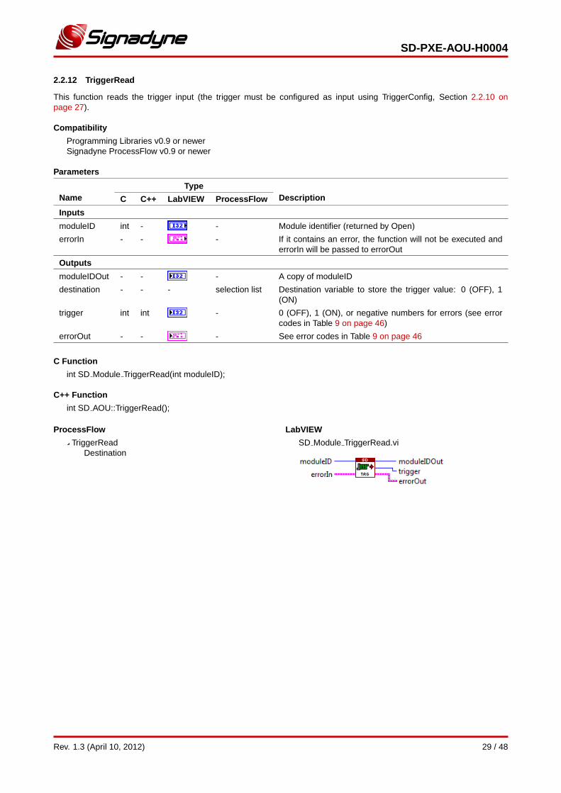
2.2.12 TriggerRead
This function reads the trigger input (the trigger must be configured as input using TriggerConfig, Section 2.2.10 onpage 27).
Compatibility
Programming Libraries v0.9 or newerSignadyne ProcessFlow v0.9 or newer
Parameters
NameType
DescriptionC C++ LabVIEW ProcessFlow
Inputs
moduleID int - - Module identifier (returned by Open)
errorIn - - - If it contains an error, the function will not be executed anderrorIn will be passed to errorOut
Outputs
moduleIDOut - - - A copy of moduleID
destination - - - selection list Destination variable to store the trigger value: 0 (OFF), 1(ON)
trigger int int - 0 (OFF), 1 (ON), or negative numbers for errors (see errorcodes in Table 9 on page 46)
errorOut - - - See error codes in Table 9 on page 46
C Function
int SD Module TriggerRead(int moduleID);
C++ Function
int SD AOU::TriggerRead();
ProcessFlow
TriggerReadDestination
LabVIEW
SD Module TriggerRead.vi
Rev. 1.3 (April 10, 2012) 29 / 48
SD-PXE-AOU-H0004
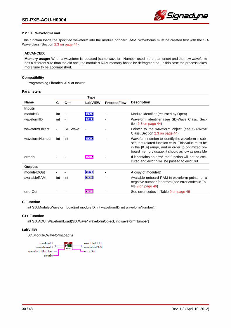
2.2.13 WaveformLoad
This function loads the specified waveform into the module onboard RAM. Waveforms must be created first with the SD-Wave class (Section 2.3 on page 44).
ADVANCED:
Memory usage: When a waveform is replaced (same waveformNumber used more than once) and the new waveformhas a different size than the old one, the module’s RAM memory has to be defragmented. In this case the process takesmore time to be accomplished.
Compatibility
Programming Libraries v0.9 or newer
Parameters
NameType
DescriptionC C++ LabVIEW ProcessFlow
Inputs
moduleID int - - Module identifier (returned by Open)
waveformID int - - Waveform identifier (see SD-Wave Class, Sec-tion 2.3 on page 44)
waveformObject - SD Wave* - - Pointer to the waveform object (see SD-WaveClass, Section 2.3 on page 44)
waveformNumber int int - Waveform number to identify the waveform in sub-sequent related function calls. This value must bein the [0..n] range, and in order to optimized on-board memory usage, it should as low as possible
errorIn - - - If it contains an error, the function will not be exe-cuted and errorIn will be passed to errorOut
Outputs
moduleIDOut - - - A copy of moduleID
availableRAM int int - Available onboard RAM in waveform points, or anegative number for errors (see error codes in Ta-ble 9 on page 46)
errorOut - - - See error codes in Table 9 on page 46
C Function
int SD Module WaveformLoad(int moduleID, int waveformID, int waveformNumber);
C++ Function
int SD AOU::WaveformLoad(SD Wave* waveformObject, int waveformNumber)
LabVIEW
SD Module WaveformLoad.vi
30 / 48 Rev. 1.3 (April 10, 2012)
SD-PXE-AOU-H0004
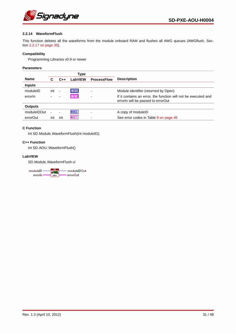
2.2.14 WaveformFlush
This function deletes all the waveforms from the module onboard RAM and flushes all AWG queues (AWGflush, Sec-tion 2.2.17 on page 35).
Compatibility
Programming Libraries v0.9 or newer
Parameters
NameType
DescriptionC C++ LabVIEW ProcessFlow
Inputs
moduleID int - - Module identifier (returned by Open)
errorIn - - - If it contains an error, the function will not be executed anderrorIn will be passed to errorOut
Outputs
moduleIDOut - - - A copy of moduleID
errorOut int int - See error codes in Table 9 on page 46
C Function
int SD Module WaveformFlush(int moduleID);
C++ Function
int SD AOU::WaveformFlush()
LabVIEW
SD Module WaveformFlush.vi
Rev. 1.3 (April 10, 2012) 31 / 48
SD-PXE-AOU-H0004
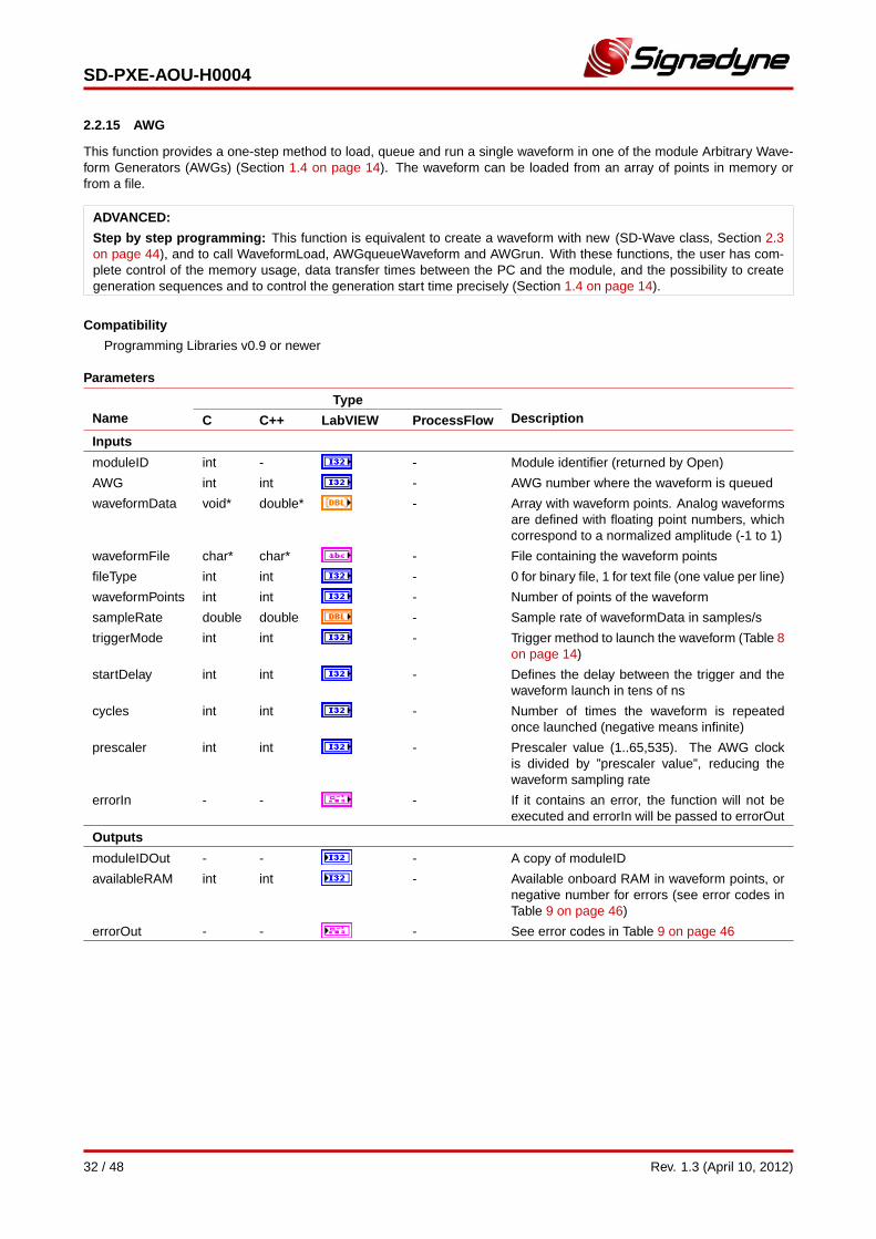
2.2.15 AWG
This function provides a one-step method to load, queue and run a single waveform in one of the module Arbitrary Wave-form Generators (AWGs) (Section 1.4 on page 14). The waveform can be loaded from an array of points in memory orfrom a file.
ADVANCED:
Step by step programming: This function is equivalent to create a waveform with new (SD-Wave class, Section 2.3on page 44), and to call WaveformLoad, AWGqueueWaveform and AWGrun. With these functions, the user has com-plete control of the memory usage, data transfer times between the PC and the module, and the possibility to creategeneration sequences and to control the generation start time precisely (Section 1.4 on page 14).
Compatibility
Programming Libraries v0.9 or newer
Parameters
NameType
DescriptionC C++ LabVIEW ProcessFlow
Inputs
moduleID int - - Module identifier (returned by Open)
AWG int int - AWG number where the waveform is queued
waveformData void* double* - Array with waveform points. Analog waveformsare defined with floating point numbers, whichcorrespond to a normalized amplitude (-1 to 1)
waveformFile char* char* - File containing the waveform points
fileType int int - 0 for binary file, 1 for text file (one value per line)
waveformPoints int int - Number of points of the waveform
sampleRate double double - Sample rate of waveformData in samples/s
triggerMode int int - Trigger method to launch the waveform (Table 8on page 14)
startDelay int int - Defines the delay between the trigger and thewaveform launch in tens of ns
cycles int int - Number of times the waveform is repeatedonce launched (negative means infinite)
prescaler int int - Prescaler value (1..65,535). The AWG clockis divided by ”prescaler value”, reducing thewaveform sampling rate
errorIn - - - If it contains an error, the function will not beexecuted and errorIn will be passed to errorOut
Outputs
moduleIDOut - - - A copy of moduleID
availableRAM int int - Available onboard RAM in waveform points, ornegative number for errors (see error codes inTable 9 on page 46)
errorOut - - - See error codes in Table 9 on page 46
32 / 48 Rev. 1.3 (April 10, 2012)
SD-PXE-AOU-H0004
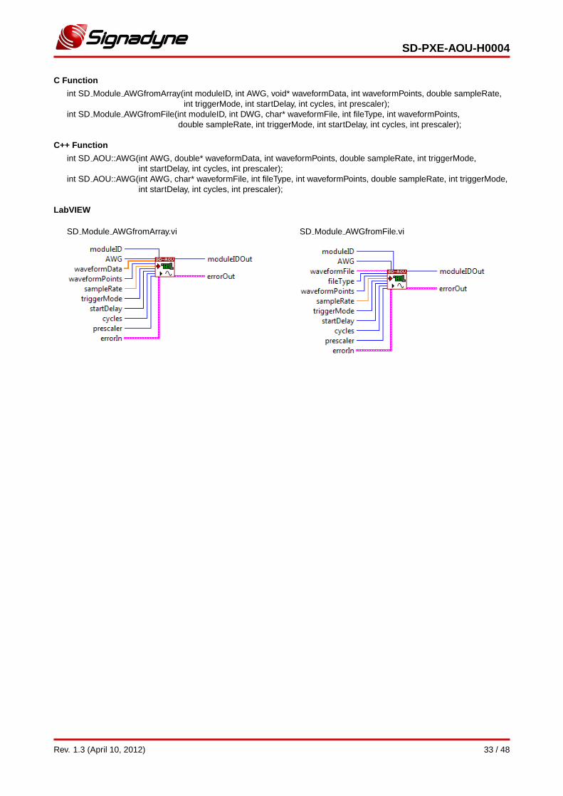
C Function
int SD Module AWGfromArray(int moduleID, int AWG, void* waveformData, int waveformPoints, double sampleRate,int triggerMode, int startDelay, int cycles, int prescaler);
int SD Module AWGfromFile(int moduleID, int DWG, char* waveformFile, int fileType, int waveformPoints,double sampleRate, int triggerMode, int startDelay, int cycles, int prescaler);
C++ Function
int SD AOU::AWG(int AWG, double* waveformData, int waveformPoints, double sampleRate, int triggerMode,int startDelay, int cycles, int prescaler);
int SD AOU::AWG(int AWG, char* waveformFile, int fileType, int waveformPoints, double sampleRate, int triggerMode,int startDelay, int cycles, int prescaler);
LabVIEW
SD Module AWGfromArray.vi SD Module AWGfromFile.vi
Rev. 1.3 (April 10, 2012) 33 / 48
SD-PXE-AOU-H0004
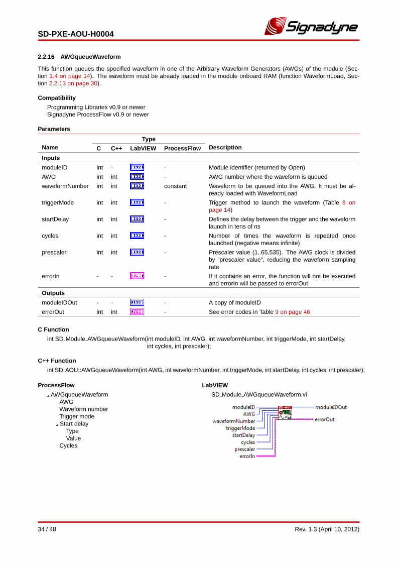
2.2.16 AWGqueueWaveform
This function queues the specified waveform in one of the Arbitrary Waveform Generators (AWGs) of the module (Sec-tion 1.4 on page 14). The waveform must be already loaded in the module onboard RAM (function WaveformLoad, Sec-tion 2.2.13 on page 30).
Compatibility
Programming Libraries v0.9 or newerSignadyne ProcessFlow v0.9 or newer
Parameters
NameType
DescriptionC C++ LabVIEW ProcessFlow
Inputs
moduleID int - - Module identifier (returned by Open)
AWG int int - AWG number where the waveform is queued
waveformNumber int int constant Waveform to be queued into the AWG. It must be al-ready loaded with WaveformLoad
triggerMode int int - Trigger method to launch the waveform (Table 8 onpage 14)
startDelay int int - Defines the delay between the trigger and the waveformlaunch in tens of ns
cycles int int - Number of times the waveform is repeated oncelaunched (negative means infinite)
prescaler int int - Prescaler value (1..65,535). The AWG clock is dividedby ”prescaler value”, reducing the waveform samplingrate
errorIn - - - If it contains an error, the function will not be executedand errorIn will be passed to errorOut
Outputs
moduleIDOut - - - A copy of moduleID
errorOut int int - See error codes in Table 9 on page 46
C Function
int SD Module AWGqueueWaveform(int moduleID, int AWG, int waveformNumber, int triggerMode, int startDelay,int cycles, int prescaler);
C++ Function
int SD AOU::AWGqueueWaveform(int AWG, int waveformNumber, int triggerMode, int startDelay, int cycles, int prescaler);
ProcessFlow
AWGqueueWaveformAWGWaveform numberTrigger modeStart delay
TypeValue
Cycles
LabVIEW
SD Module AWGqueueWaveform.vi
34 / 48 Rev. 1.3 (April 10, 2012)
SD-PXE-AOU-H0004
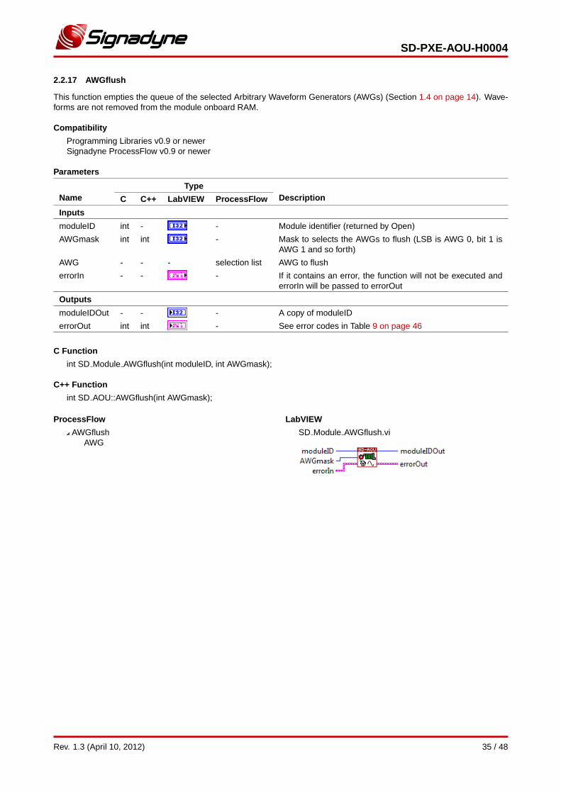
2.2.17 AWGflush
This function empties the queue of the selected Arbitrary Waveform Generators (AWGs) (Section 1.4 on page 14). Wave-forms are not removed from the module onboard RAM.
Compatibility
Programming Libraries v0.9 or newerSignadyne ProcessFlow v0.9 or newer
Parameters
NameType
DescriptionC C++ LabVIEW ProcessFlow
Inputs
moduleID int - - Module identifier (returned by Open)
AWGmask int int - Mask to selects the AWGs to flush (LSB is AWG 0, bit 1 isAWG 1 and so forth)
AWG - - - selection list AWG to flush
errorIn - - - If it contains an error, the function will not be executed anderrorIn will be passed to errorOut
Outputs
moduleIDOut - - - A copy of moduleID
errorOut int int - See error codes in Table 9 on page 46
C Function
int SD Module AWGflush(int moduleID, int AWGmask);
C++ Function
int SD AOU::AWGflush(int AWGmask);
ProcessFlow
AWGflushAWG
LabVIEW
SD Module AWGflush.vi
Rev. 1.3 (April 10, 2012) 35 / 48
SD-PXE-AOU-H0004
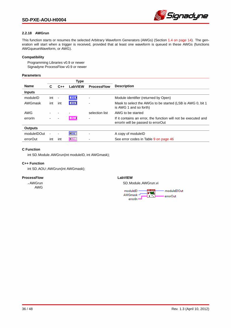
2.2.18 AWGrun
This function starts or resumes the selected Arbitrary Waveform Generators (AWGs) (Section 1.4 on page 14). The gen-eration will start when a trigger is received, provided that at least one waveform is queued in these AWGs (functionsAWGqueueWaveform, or AWG).
Compatibility
Programming Libraries v0.9 or newerSignadyne ProcessFlow v0.9 or newer
Parameters
NameType
DescriptionC C++ LabVIEW ProcessFlow
Inputs
moduleID int - - Module identifier (returned by Open)
AWGmask int int - Mask to select the AWGs to be started (LSB is AWG 0, bit 1is AWG 1 and so forth)
AWG - - - selection list AWG to be started
errorIn - - - If it contains an error, the function will not be executed anderrorIn will be passed to errorOut
Outputs
moduleIDOut - - - A copy of moduleID
errorOut int int - See error codes in Table 9 on page 46
C Function
int SD Module AWGrun(int moduleID, int AWGmask);
C++ Function
int SD AOU::AWGrun(int AWGmask);
ProcessFlow
AWGrunAWG
LabVIEW
SD Module AWGrun.vi
36 / 48 Rev. 1.3 (April 10, 2012)
SD-PXE-AOU-H0004
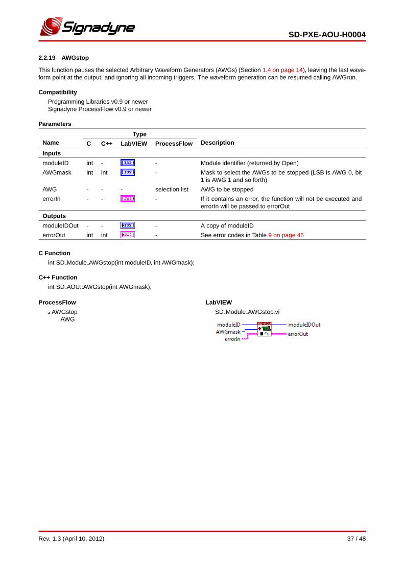
2.2.19 AWGstop
This function pauses the selected Arbitrary Waveform Generators (AWGs) (Section 1.4 on page 14), leaving the last wave-form point at the output, and ignoring all incoming triggers. The waveform generation can be resumed calling AWGrun.
Compatibility
Programming Libraries v0.9 or newerSignadyne ProcessFlow v0.9 or newer
Parameters
NameType
DescriptionC C++ LabVIEW ProcessFlow
Inputs
moduleID int - - Module identifier (returned by Open)
AWGmask int int - Mask to select the AWGs to be stopped (LSB is AWG 0, bit1 is AWG 1 and so forth)
AWG - - - selection list AWG to be stopped
errorIn - - - If it contains an error, the function will not be executed anderrorIn will be passed to errorOut
Outputs
moduleIDOut - - - A copy of moduleID
errorOut int int - See error codes in Table 9 on page 46
C Function
int SD Module AWGstop(int moduleID, int AWGmask);
C++ Function
int SD AOU::AWGstop(int AWGmask);
ProcessFlow
AWGstopAWG
LabVIEW
SD Module AWGstop.vi
Rev. 1.3 (April 10, 2012) 37 / 48
SD-PXE-AOU-H0004
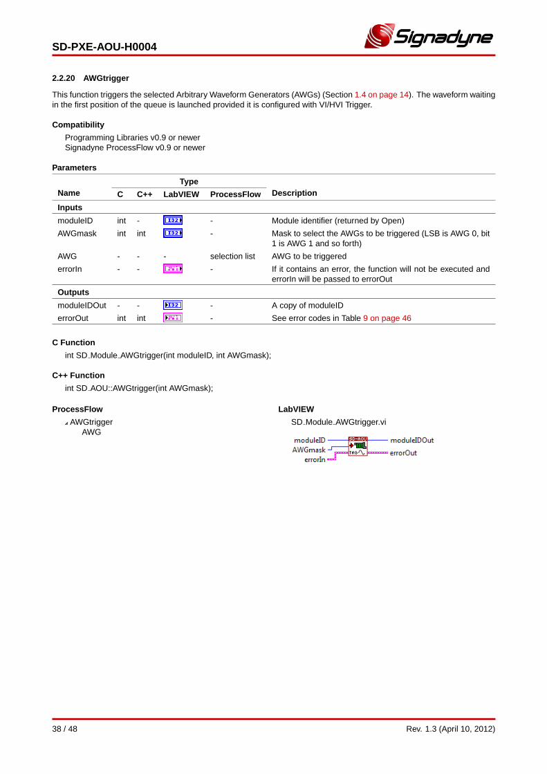
2.2.20 AWGtrigger
This function triggers the selected Arbitrary Waveform Generators (AWGs) (Section 1.4 on page 14). The waveform waitingin the first position of the queue is launched provided it is configured with VI/HVI Trigger.
Compatibility
Programming Libraries v0.9 or newerSignadyne ProcessFlow v0.9 or newer
Parameters
NameType
DescriptionC C++ LabVIEW ProcessFlow
Inputs
moduleID int - - Module identifier (returned by Open)
AWGmask int int - Mask to select the AWGs to be triggered (LSB is AWG 0, bit1 is AWG 1 and so forth)
AWG - - - selection list AWG to be triggered
errorIn - - - If it contains an error, the function will not be executed anderrorIn will be passed to errorOut
Outputs
moduleIDOut - - - A copy of moduleID
errorOut int int - See error codes in Table 9 on page 46
C Function
int SD Module AWGtrigger(int moduleID, int AWGmask);
C++ Function
int SD AOU::AWGtrigger(int AWGmask);
ProcessFlow
AWGtriggerAWG
LabVIEW
SD Module AWGtrigger.vi
38 / 48 Rev. 1.3 (April 10, 2012)
SD-PXE-AOU-H0004
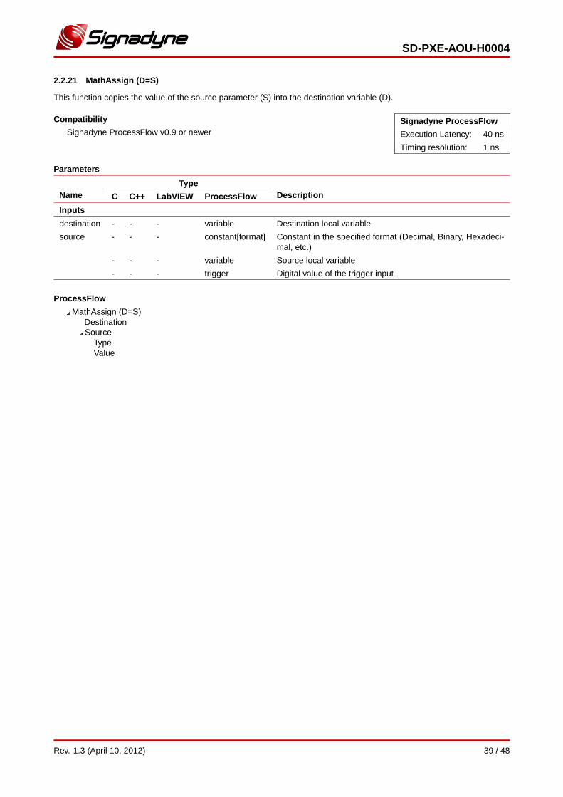
2.2.21 MathAssign (D=S)
This function copies the value of the source parameter (S) into the destination variable (D).
Compatibility
Signadyne ProcessFlow v0.9 or newerSignadyne ProcessFlow
Execution Latency: 40 ns
Timing resolution: 1 ns
Parameters
NameType
DescriptionC C++ LabVIEW ProcessFlow
Inputs
destination - - - variable Destination local variable
source - - - constant[format] Constant in the specified format (Decimal, Binary, Hexadeci-mal, etc.)
- - - variable Source local variable
- - - trigger Digital value of the trigger input
ProcessFlow
MathAssign (D=S)DestinationSource
TypeValue
Rev. 1.3 (April 10, 2012) 39 / 48

SD-PXE-AOU-H0004
2.2.22 MathArithmetics (R=A[+-*/]B)
This function subtracts, adds, multiplies or divides the values of the operands A and B, writing the result in R.
Compatibility
Signadyne ProcessFlow v0.9 or newerSignadyne ProcessFlow
Execution Latency: 40 ns
Timing resolution: 1 ns
Parameters
NameType
DescriptionC C++ LabVIEW ProcessFlow
Inputs
Result - - - variable Destination local variable
A - - - constant[format] Constant in the specified format (Decimal, Binary, Hexadeci-mal, etc.)
- - - variable Local variable
- - - trigger Digital value of the trigger input
Operation - - - selection list Arithmetic operation (+, -, *, /)
B - - - constant[format] Constant in the specified format (Decimal, Binary, Hexadeci-mal, etc.)
- - - variable Local variable
- - - trigger Digital value of the trigger input
ProcessFlow
MathArithmetics (R=A[+-*/]B)ResultA
TypeValue
OperationB
TypeValue
40 / 48 Rev. 1.3 (April 10, 2012)
SD-PXE-AOU-H0004
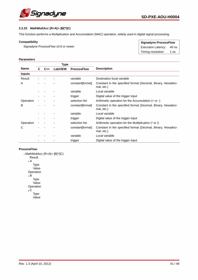
2.2.23 MathMultAcc (R=A[+-]B[*/]C)
This function performs a Multiplication and Accumulation (MAC) operation, widely used in digital signal processing.
Compatibility
Signadyne ProcessFlow v0.9 or newerSignadyne ProcessFlow
Execution Latency: 40 ns
Timing resolution: 1 ns
Parameters
NameType
DescriptionC C++ LabVIEW ProcessFlow
Inputs
Result - - - variable Destination local variable
A - - - constant[format] Constant in the specified format (Decimal, Binary, Hexadeci-mal, etc.)
- - - variable Local variable
- - - trigger Digital value of the trigger input
Operation - - - selection list Arithmetic operation for the Accumulation (+ or -)
B - - - constant[format] Constant in the specified format (Decimal, Binary, Hexadeci-mal, etc.)
- - - variable Local variable
- - - trigger Digital value of the trigger input
Operation - - - selection list Arithmetic operation for the Multiplication (* or /)
C - - - constant[format] Constant in the specified format (Decimal, Binary, Hexadeci-mal, etc.)
- - - variable Local variable
- - - trigger Digital value of the trigger input
ProcessFlow
MathMultAcc (R=A[+-]B[*/]C)ResultA
TypeValue
OperationB
TypeValue
OperationC
TypeValue
Rev. 1.3 (April 10, 2012) 41 / 48
SD-PXE-AOU-H0004
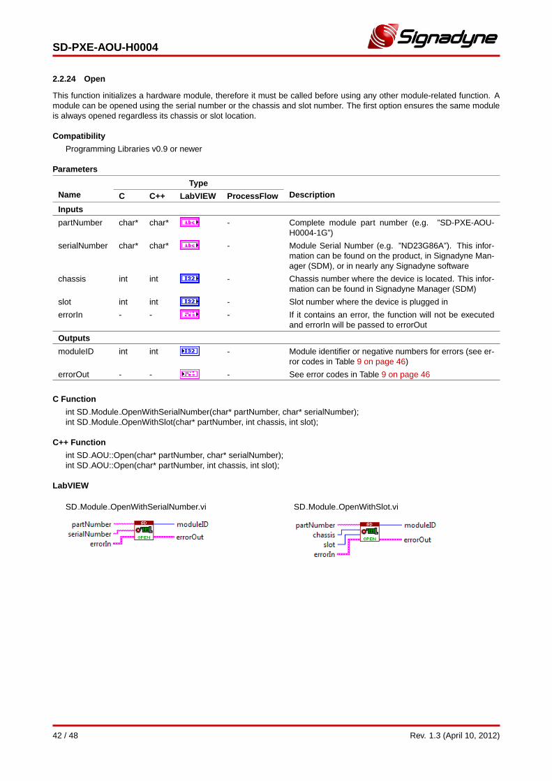
2.2.24 Open
This function initializes a hardware module, therefore it must be called before using any other module-related function. Amodule can be opened using the serial number or the chassis and slot number. The first option ensures the same moduleis always opened regardless its chassis or slot location.
Compatibility
Programming Libraries v0.9 or newer
Parameters
NameType
DescriptionC C++ LabVIEW ProcessFlow
Inputs
partNumber char* char* - Complete module part number (e.g. ”SD-PXE-AOU-H0004-1G”)
serialNumber char* char* - Module Serial Number (e.g. ”ND23G86A”). This infor-mation can be found on the product, in Signadyne Man-ager (SDM), or in nearly any Signadyne software
chassis int int - Chassis number where the device is located. This infor-mation can be found in Signadyne Manager (SDM)
slot int int - Slot number where the device is plugged in
errorIn - - - If it contains an error, the function will not be executedand errorIn will be passed to errorOut
Outputs
moduleID int int - Module identifier or negative numbers for errors (see er-ror codes in Table 9 on page 46)
errorOut - - - See error codes in Table 9 on page 46
C Function
int SD Module OpenWithSerialNumber(char* partNumber, char* serialNumber);int SD Module OpenWithSlot(char* partNumber, int chassis, int slot);
C++ Function
int SD AOU::Open(char* partNumber, char* serialNumber);int SD AOU::Open(char* partNumber, int chassis, int slot);
LabVIEW
SD Module OpenWithSerialNumber.vi SD Module OpenWithSlot.vi
42 / 48 Rev. 1.3 (April 10, 2012)
SD-PXE-AOU-H0004
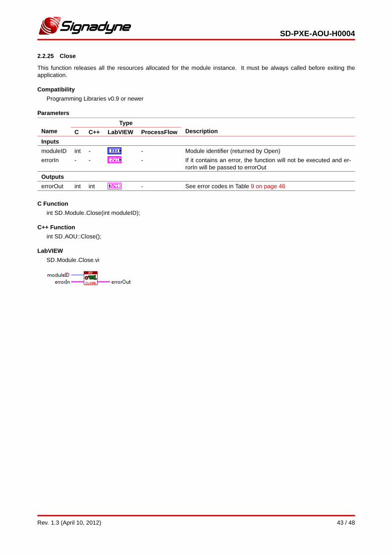
2.2.25 Close
This function releases all the resources allocated for the module instance. It must be always called before exiting theapplication.
Compatibility
Programming Libraries v0.9 or newer
Parameters
NameType
DescriptionC C++ LabVIEW ProcessFlow
Inputs
moduleID int - - Module identifier (returned by Open)
errorIn - - - If it contains an error, the function will not be executed and er-rorIn will be passed to errorOut
Outputs
errorOut int int - See error codes in Table 9 on page 46
C Function
int SD Module Close(int moduleID);
C++ Function
int SD AOU::Close();
LabVIEW
SD Module Close.vi
Rev. 1.3 (April 10, 2012) 43 / 48
SD-PXE-AOU-H0004
2.3 SD-Wave Class Functions
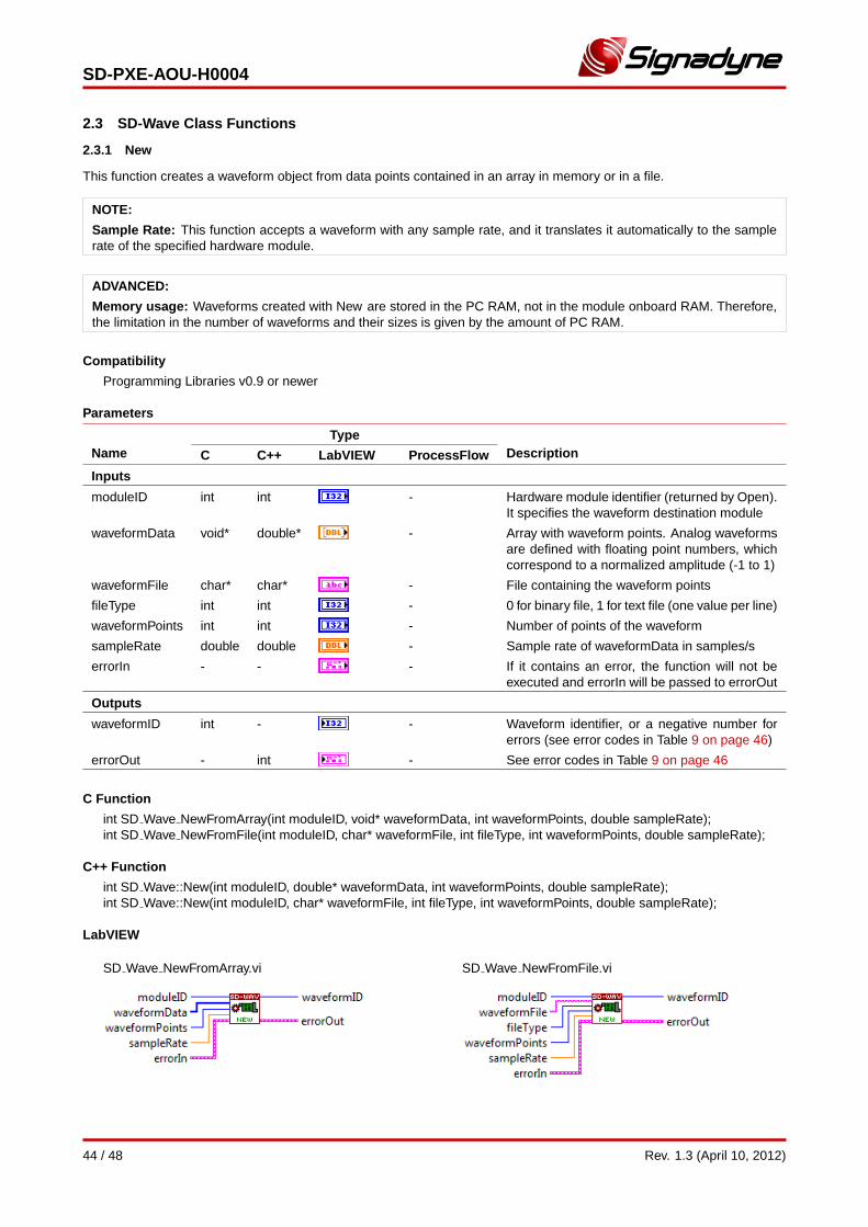
2.3.1 New
This function creates a waveform object from data points contained in an array in memory or in a file.
NOTE:
Sample Rate: This function accepts a waveform with any sample rate, and it translates it automatically to the samplerate of the specified hardware module.
ADVANCED:
Memory usage: Waveforms created with New are stored in the PC RAM, not in the module onboard RAM. Therefore,the limitation in the number of waveforms and their sizes is given by the amount of PC RAM.
Compatibility
Programming Libraries v0.9 or newer
Parameters
NameType
DescriptionC C++ LabVIEW ProcessFlow
Inputs
moduleID int int - Hardware module identifier (returned by Open).It specifies the waveform destination module
waveformData void* double* - Array with waveform points. Analog waveformsare defined with floating point numbers, whichcorrespond to a normalized amplitude (-1 to 1)
waveformFile char* char* - File containing the waveform points
fileType int int - 0 for binary file, 1 for text file (one value per line)
waveformPoints int int - Number of points of the waveform
sampleRate double double - Sample rate of waveformData in samples/s
errorIn - - - If it contains an error, the function will not beexecuted and errorIn will be passed to errorOut
Outputs
waveformID int - - Waveform identifier, or a negative number forerrors (see error codes in Table 9 on page 46)
errorOut - int - See error codes in Table 9 on page 46
C Function
int SD Wave NewFromArray(int moduleID, void* waveformData, int waveformPoints, double sampleRate);int SD Wave NewFromFile(int moduleID, char* waveformFile, int fileType, int waveformPoints, double sampleRate);
C++ Function
int SD Wave::New(int moduleID, double* waveformData, int waveformPoints, double sampleRate);int SD Wave::New(int moduleID, char* waveformFile, int fileType, int waveformPoints, double sampleRate);
LabVIEW
SD Wave NewFromArray.vi SD Wave NewFromFile.vi
44 / 48 Rev. 1.3 (April 10, 2012)
SD-PXE-AOU-H0004
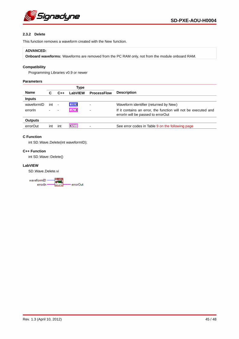
2.3.2 Delete
This function removes a waveform created with the New function.
ADVANCED:
Onboard waveforms: Waveforms are removed from the PC RAM only, not from the module onboard RAM.
Compatibility
Programming Libraries v0.9 or newer
Parameters
NameType
DescriptionC C++ LabVIEW ProcessFlow
Inputs
waveformID int - - Waveform identifier (returned by New)
errorIn - - - If it contains an error, the function will not be executed anderrorIn will be passed to errorOut
Outputs
errorOut int int - See error codes in Table 9 on the following page
C Function
int SD Wave Delete(int waveformID);
C++ Function
int SD Wave::Delete()
LabVIEW
SD Wave Delete.vi
Rev. 1.3 (April 10, 2012) 45 / 48
SD-PXE-AOU-H0004
2.4 Error Codes
error errorDescription
-1 Wrong module slot
-2 Wrong module chassis
-2 Wrong serial number
-3 Wrong devicesID
-4 Wrong channel
-5 Wrong clock configuration
others No error
Table 9: Software error codes
46 / 48 Rev. 1.3 (April 10, 2012)
SD-PXE-AOU-H0004
References
[1] Signadyne VirtualKnob, Software Front Panels. Product Website.
[2] Signadyne Programming Libraries for Virtual Instrumentation. Product Website.
[3] Signadyne ProcessFlow, Hard Virtual Instrument (HVI) Programming Environment. Product Website.
[4] SD-PXE-AOU-H0001, 2 Channels, 500 MSPS, Analog Output PXI Express Module. Product Website.
[5] SD-PXE-AOU-H0002, 4 Channels, 500 MSPS, Analog Output PXI Express Module. Product Website.
[6] SD-PXE-AOU-H0003, 2 Channels, 1 GSPS, Analog Output PXI Express Module. Product Website.
Rev. 1.3 (April 10, 2012) 47 / 48
SD-PXE-AOU-H0004
SD-PXE-AOU-H00044 Channels, 1 GSPS, Analog Output PXI Express Module
Rev. 1.3 (April 10, 2012)
Signadyne and its subsidiaries reserve the right to makecorrections, modifications, enhancements, improvements,and other changes to its products and services at any time.
Information delivered by Signadyne is believed to be ac-curate and reliable. However, no responsibility is assumedby Signadyne for its use, nor for any infringements of patentsor other rights of third parties that may result from its use.
No license is granted by implication or otherwise underany patent or patent rights of Signadyne.
Trademarks and registered trademarks are the propertyof their respective owners.
c©2012 Signadyne. All rights reserved.
www.signadyne.com
48 / 48 Rev. 1.3 (April 10, 2012)