ROOM AIR CONDITIONER WALL MOUNTED TYPE HEAT · PDF fileEspañol Italiano...
15
KEEP THIS OPERATION MANUAL FOR FUTURE REFERENCE English Deutsch Français Español Italiano EλληvIkά OPERATING MANUAL BEDIENUNGSANLEITUNG MODE D’EMPLOI MANUAL DE FUNCIONAMIENTO MANUALE DI ISTRUZIONI ΕΓΕΙΡΙ∆Ι ΛΕΙΤΥΡΓΙΑΣ MANUAL DE INSTRUÇÕES РУКОВОДСТВО ПО ЭКСПЛУАТАЦИИ P/N9312855018-01 ROOM AIR CONDITIONER WALL MOUNTED TYPE HEAT & COOL MODEL (REVERSE CYCLE) Português Русский
Transcript of ROOM AIR CONDITIONER WALL MOUNTED TYPE HEAT · PDF fileEspañol Italiano...

KEEP THIS OPERATION MANUALFOR FUTURE REFERENCE
En
gli
sh
De
uts
ch
Fra
nçais
Esp
añ
ol
Ita
lia
no
Eλλ
ηvI
kά
OPERATING MANUALBEDIENUNGSANLEITUNGMODE D’EMPLOIMANUAL DE FUNCIONAMIENTOMANUALE DI ISTRUZIONIΕΓΕΙΡΙ∆Ι� ΛΕΙΤ�ΥΡΓΙΑΣMANUAL DE INSTRUÇÕESРУКОВОДСТВО ПО ЭКСПЛУАТАЦИИ
P/N9312855018-01
ROOM AIR CONDITIONER
WALL MOUNTED TYPE
HEAT & COOL MODEL(REVERSE CYCLE)
Po
rtu
gu
ês
Рус
ски
й
9312855018_Cover.pm6.5 03.7.29, 10:55 AM1
#
-
9
$
0@
3
=
~
!
%
1
4
5
6
8
2
7
^
OPERATION
TIMER
SWING
)
ª
≠
– ⁄ ºŸ
*
&
(
_
+
•
£
∞
§
¶
™
¡
¢
Fig. 5
Fig. 1
Fig. 2
Fig. 3
Fig. 4
Fig. 7
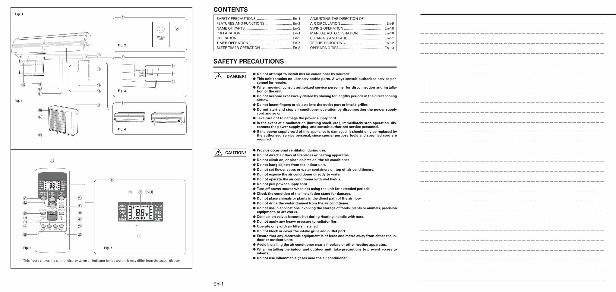
CONTENTS
SAFETY PRECAUTIONS .................................... En-1FEATURES AND FUNCTIONS ........................... En-2NAME OF PARTS ................................................ En-3PREPARATION .................................................... En-4OPERATION ........................................................ En-5TIMER OPERATION ............................................ En-7SLEEP TIMER OPERATION ................................ En-8
ADJUSTING THE DIRECTION OFAIR CIRCULATION .............................................. En-9SWING OPERATION ......................................... En-10MANUAL AUTO OPERATION .......................... En-10CLEANING AND CARE ..................................... En-11TROUBLESHOOTING ....................................... En-12OPERATING TIPS.............................................. En-13
SAFETY PRECAUTIONS
� Do not attempt to install this air conditioner by yourself.
� This unit contains no user-serviceable parts. Always consult authorized service per-sonnel for repairs.
� When moving, consult authorized service personnel for disconnection and installa-tion of the unit.
� Do not become excessively chilled by staying for lengthy periods in the direct coolingairflow.
� Do not insert fingers or objects into the outlet port or intake grilles.
� Do not start and stop air conditioner operation by disconnecting the power supplycord and so on.
� Take care not to damage the power supply cord.
� In the event of a malfunction (burning smell, etc.), immediately stop operation, dis-connect the power supply plug, and consult authorized service personnel.
� If the power supply cord of this appliance is damaged, it should only be replaced bythe authorized service personal, since special purpose tools and specified cord arerequired.
� Provide occasional ventilation during use.
� Do not direct air flow at fireplaces or heating apparatus.
� Do not climb on, or place objects on, the air conditioner.
� Do not hang objects from the indoor unit.
� Do not set flower vases or water containers on top of air conditioners.
� Do not expose the air conditioner directly to water.
� Do not operate the air conditioner with wet hands.
� Do not pull power supply cord.
� Turn off power source when not using the unit for extended periods.
� Check the condition of the installation stand for damage.
� Do not place animals or plants in the direct path of the air flow.
� Do not drink the water drained from the air conditioner.
� Do not use in applications involving the storage of foods, plants or animals, precisionequipment, or art works.
� Connection valves become hot during Heating; handle with care.
� Do not apply any heavy pressure to radiator fins.
� Operate only with air filters installed.
� Do not block or cover the intake grille and outlet port.
� Ensure that any electronic equipment is at least one metre away from either the in-door or outdoor units.
� Avoid installing the air conditioner near a fireplace or other heating apparatus.
� When installing the indoor and outdoor unit, take precautions to prevent access toinfants.
� Do not use inflammable gases near the air conditioner.
DANGER!
CAUTION!
En-1
This figure shows the control display when all indicator lamps are on. It may differ from the actual display.
Fig. 6
9312855018_Cover.pm6.5 03.7.29, 10:55 AM2
En-2
FEATURES AND FUNCTIONS
AUTO CHANGEOVER
The operation mode (cooling, dry, heating) is switched au-tomatically to maintain the set temperature, and the tem-perature is kept constant at all times.
SLEEP TIMER
When the SLEEP button is pressed during Heating mode,the air conditioner’s thermostat setting is gradually loweredduring the period of operation; during cooling mode, thethermostat setting is gradually raised during the period ofoperation. When the set time is reached, the unit automati-cally turns off.
WIRELESS REMOTE CONTROL UNIT
The Wireless Remote Control Unit allows convenient con-trol of air conditioner operation.
SWING OPERATION
The Air Flow Direction Louvers swings automatically up anddown so that the air speeds to every nook and corner ofyour room.
REMOVABLE INTAKE GRILLE
The indoor unit’s Intake Grille can be removed for easy clean-ing and maintenance.
MILDEW-RESISTANT FILTER
The AIR FILTER has been treated to resist mildew growth,thus allowing cleaner use and easier care.
SUPER QUIET OPERATION
When the FAN CONTROL button is used to select QUIET,the unit begins super-quiet operation; the indoor unit’s air-flow is reduced to produce quieter operation.
AIR CLEANING FILTER (Optional)
The optional Air Cleaning Filter (Model APS-03B) uses anelectrostatic principle to clean the air of fine particulatematter such as tobacco smoke and plant pollen.
9312175017-01_en.pm6.5 03.7.29, 9:33 AM2
En-3
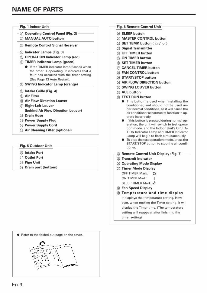
Fig. 1 Indoor Unit
1 Operating Control Panel (Fig. 2)
2 MANUAL AUTO button
3 Remote Control Signal Receiver
4 Indicator Lamps (Fig. 3)
5 OPERATION Indicator Lamp (red)
6 TIMER Indicator Lamp (green)
� If the TIMER indicator lamp flashes whenthe timer is operating, it indicates that afault has occurred with the timer setting(See Page 13 Auto Restart).
7 SWING Indicator Lamp (orange)
8 Intake Grille (Fig. 4)
9 Air Filter
0 Air Flow Direction Louver
A Right-Left Louver
(behind Air Flow Direction Louver)
B Drain Hose
C Power Supply Plug
D Power Supply Cord
E Air Cleaning Filter (optional)
Fig. 5 Outdoor Unit
F Intake Port
G Outlet Port
H Pipe Unit
I Drain port (bottom)
Fig. 6 Remote Control Unit
J SLEEP button
K MASTER CONTROL button
L SET TEMP. button ( / )
M Signal Transmitter
N OFF TIMER button
O ON TIMER button
P SET TIMER button
Q CANCEL TIMER button
R FAN CONTROL button
S START/STOP button
T AIR FLOW DIRECTION button
U SWING LOUVER button
V ACL button
W TEST RUN button
� This button is used when installing theconditioner, and should not be used un-der normal conditions, as it will cause theair conditioner’s thermostat function to op-erate incorrectly.
� If this button is pressed during normal op-eration, the unit will switch to test opera-tion mode, and the Indoor Unit’s OPERA-TION Indicator Lamp and TIMER IndicatorLamp will begin to flash simultaneously.
� To stop the test operation mode, press theSTART/STOP button to stop the air condi-tioner.
X Remote Control Unit Display (Fig. 7)
Y Transmit Indicator
Z Operating Mode Display
[ Timer Mode Display
OFF TIMER Mark:
ON TIMER Mark:
SLEEP TIMER Mark:
\ Fan Speed Display
] Temperature and t ime d isp lay
It displays the temperature setting. How-
ever, when making the Timer setting, it will
display the Timer time. (The temperature
setting will reappear after finishing the
timer setting)
NAME OF PARTS
� Refer to the folded out page on the cover.
9312175017-01_en.pm6.5 03.7.29, 9:33 AM3
En-4
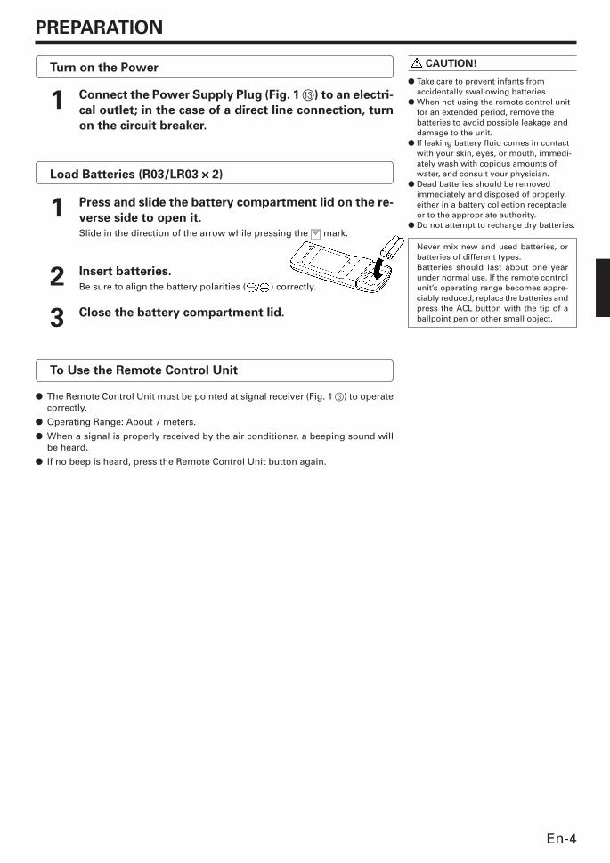
PREPARATION
CAUTION!
� Take care to prevent infants fromaccidentally swallowing batteries.
� When not using the remote control unitfor an extended period, remove thebatteries to avoid possible leakage anddamage to the unit.
� If leaking battery fluid comes in contactwith your skin, eyes, or mouth, immedi-ately wash with copious amounts ofwater, and consult your physician.
� Dead batteries should be removedimmediately and disposed of properly,either in a battery collection receptacleor to the appropriate authority.
� Do not attempt to recharge dry batteries.
Never mix new and used batteries, orbatteries of different types.Batteries should last about one yearunder normal use. If the remote controlunit’s operating range becomes appre-ciably reduced, replace the batteries andpress the ACL button with the tip of aballpoint pen or other small object.
Turn on the Power
1 Connect the Power Supply Plug (Fig. 1 C) to an electri-
cal outlet; in the case of a direct line connection, turn
on the circuit breaker.
Load Batteries (R03/LR03 ××××× 2)
1 Press and slide the battery compartment lid on the re-
verse side to open it.
Slide in the direction of the arrow while pressing the mark.
2 Insert batteries.
Be sure to align the battery polarities ( ) correctly.
3 Close the battery compartment lid.
To Use the Remote Control Unit
� The Remote Control Unit must be pointed at signal receiver (Fig. 1 3) to operatecorrectly.
� Operating Range: About 7 meters.
� When a signal is properly received by the air conditioner, a beeping sound willbe heard.
� If no beep is heard, press the Remote Control Unit button again.
9312175017-01_en.pm6.5 03.7.29, 9:33 AM4
En-5
To Select Mode Operation
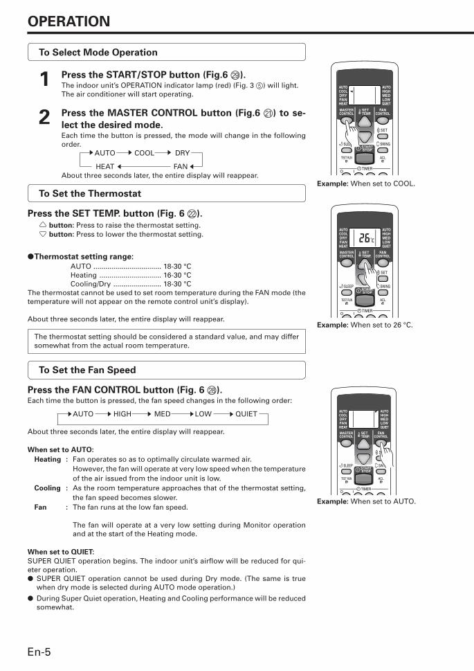
1 Press the START/STOP button (Fig.6 S).The indoor unit’s OPERATION indicator lamp (red) (Fig. 3 5) will light.The air conditioner will start operating.
2 Press the MASTER CONTROL button (Fig.6 K) to se-
lect the desired mode.Each time the button is pressed, the mode will change in the followingorder.
AUTO COOL DRY
HEAT FANAbout three seconds later, the entire display will reappear.
To Set the Thermostat
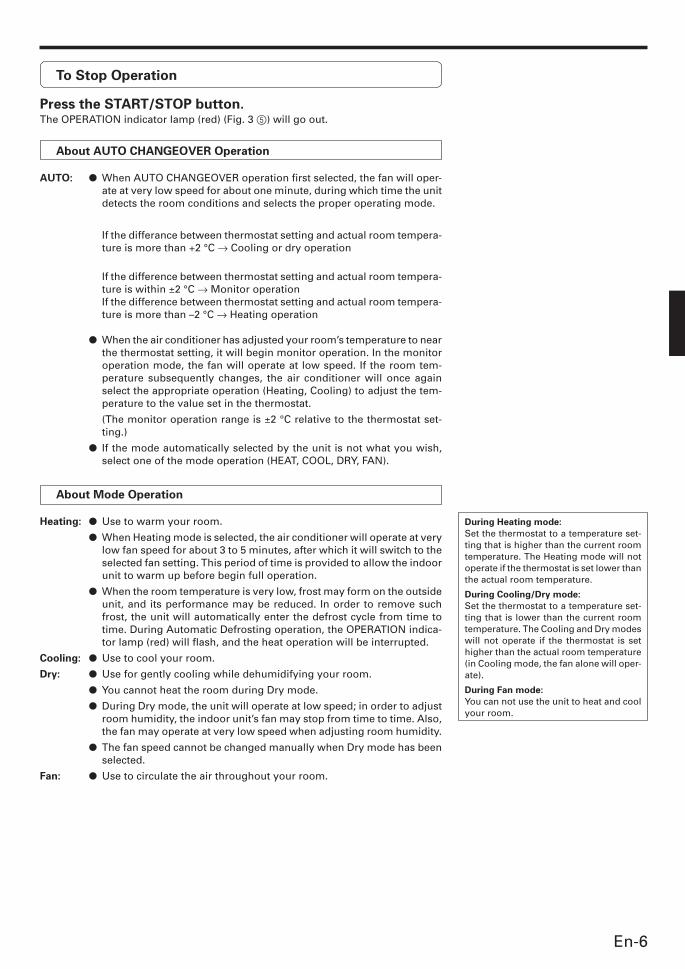
Press the SET TEMP. button (Fig. 6 L).
button: Press to raise the thermostat setting. button: Press to lower the thermostat setting.
�Thermostat setting range:
AUTO .................................. 18-30 °CHeating ............................... 16-30 °CCooling/Dry ........................ 18-30 °C
The thermostat cannot be used to set room temperature during the FAN mode (thetemperature will not appear on the remote control unit’s display).
About three seconds later, the entire display will reappear.
The thermostat setting should be considered a standard value, and may differsomewhat from the actual room temperature.
To Set the Fan Speed
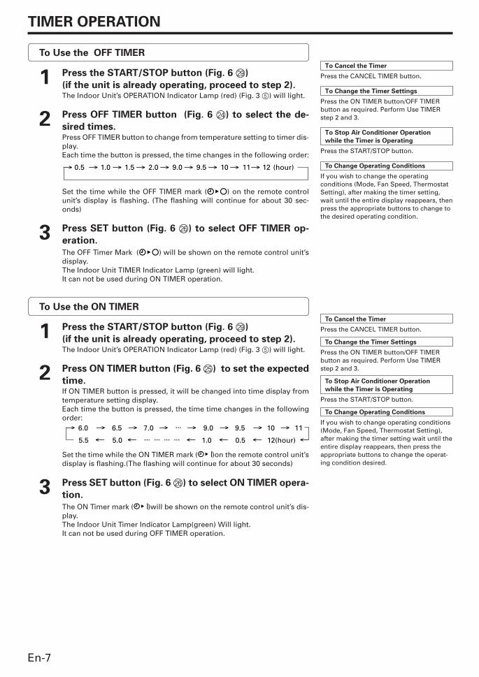
Press the FAN CONTROL button (Fig. 6 R).Each time the button is pressed, the fan speed changes in the following order:
AUTO HIGH MED LOW QUIET
About three seconds later, the entire display will reappear.
When set to AUTO:
Heating : Fan operates so as to optimally circulate warmed air.However, the fan will operate at very low speed when the temperatureof the air issued from the indoor unit is low.
Cooling : As the room temperature approaches that of the thermostat setting,the fan speed becomes slower.
Fan : The fan runs at the low fan speed.
The fan will operate at a very low setting during Monitor operationand at the start of the Heating mode.
When set to QUIET:
SUPER QUIET operation begins. The indoor unit’s airflow will be reduced for qui-eter operation.� SUPER QUIET operation cannot be used during Dry mode. (The same is true
when dry mode is selected during AUTO mode operation.)
� During Super Quiet operation, Heating and Cooling performance will be reducedsomewhat.
OPERATION
s sss
Example: When set to COOL.
Example: When set to 26 °C.
Example: When set to AUTO.
s
s s s
tt
9312175017-01_en.pm6.5 03.7.29, 9:33 AM5
En-6
To Stop Operation
Press the START/STOP button.The OPERATION indicator lamp (red) (Fig. 3 5) will go out.
About AUTO CHANGEOVER Operation
AUTO: � When AUTO CHANGEOVER operation first selected, the fan will oper-ate at very low speed for about one minute, during which time the unitdetects the room conditions and selects the proper operating mode.
If the differance between thermostat setting and actual room tempera-ture is more than +2 °C → Cooling or dry operation
If the difference between thermostat setting and actual room tempera-ture is within ±2 °C → Monitor operationIf the difference between thermostat setting and actual room tempera-ture is more than –2 °C → Heating operation
� When the air conditioner has adjusted your room’s temperature to nearthe thermostat setting, it will begin monitor operation. In the monitoroperation mode, the fan will operate at low speed. If the room tem-perature subsequently changes, the air conditioner will once againselect the appropriate operation (Heating, Cooling) to adjust the tem-perature to the value set in the thermostat.
(The monitor operation range is ±2 °C relative to the thermostat set-ting.)
� If the mode automatically selected by the unit is not what you wish,select one of the mode operation (HEAT, COOL, DRY, FAN).
About Mode Operation
Heating: � Use to warm your room.
� When Heating mode is selected, the air conditioner will operate at verylow fan speed for about 3 to 5 minutes, after which it will switch to theselected fan setting. This period of time is provided to allow the indoorunit to warm up before begin full operation.
� When the room temperature is very low, frost may form on the outsideunit, and its performance may be reduced. In order to remove suchfrost, the unit will automatically enter the defrost cycle from time totime. During Automatic Defrosting operation, the OPERATION indica-tor lamp (red) will flash, and the heat operation will be interrupted.
Cooling: � Use to cool your room.
Dry: � Use for gently cooling while dehumidifying your room.
� You cannot heat the room during Dry mode.
� During Dry mode, the unit will operate at low speed; in order to adjustroom humidity, the indoor unit’s fan may stop from time to time. Also,the fan may operate at very low speed when adjusting room humidity.
� The fan speed cannot be changed manually when Dry mode has beenselected.
Fan: � Use to circulate the air throughout your room.
During Heating mode:
Set the thermostat to a temperature set-ting that is higher than the current roomtemperature. The Heating mode will notoperate if the thermostat is set lower thanthe actual room temperature.
During Cooling/Dry mode:
Set the thermostat to a temperature set-ting that is lower than the current roomtemperature. The Cooling and Dry modeswill not operate if the thermostat is sethigher than the actual room temperature(in Cooling mode, the fan alone will oper-ate).
During Fan mode:
You can not use the unit to heat and coolyour room.
9312175017-01_en.pm6.5 03.7.29, 9:33 AM6
En-7
TIMER OPERATION
To Use the OFF TIMER
1 Press the START/STOP button (Fig. 6 S)
(if the unit is already operating, proceed to step 2).The Indoor Unit’s OPERATION Indicator Lamp (red) (Fig. 3 5) will light.
2 Press OFF TIMER button (Fig. 6 N) to select the de-
sired times.Press OFF TIMER button to change from temperature setting to timer dis-play.Each time the button is pressed, the time changes in the following order:
Set the time while the OFF TIMER mark ( ) on the remote controlunit’s display is flashing. (The flashing will continue for about 30 sec-onds)
3 Press SET button (Fig. 6 P) to select OFF TIMER op-
eration.
The OFF Timer Mark ( ) will be shown on the remote control unit’sdisplay.The Indoor Unit TIMER Indicator Lamp (green) will light.It can not be used during ON TIMER operation.
To Use the ON TIMER
1 Press the START/STOP button (Fig. 6 S)
(if the unit is already operating, proceed to step 2).The Indoor Unit’s OPERATION Indicator Lamp (red) (Fig. 3 5) will light.
2 Press ON TIMER button (Fig. 6 O) to set the expected
time.If ON TIMER button is pressed, it will be changed into time display fromtemperature setting display.Each time the button is pressed, the time time changes in the followingorder:
Set the time while the ON TIMER mark ( )on the remote control unit’sdisplay is flashing.(The flashing will continue for about 30 seconds)
3 Press SET button (Fig. 6 P) to select ON TIMER opera-
tion.
The ON Timer mark ( )will be shown on the remote control unit’s dis-play.The Indoor Unit Timer Indicator Lamp(green) Will light.It can not be used during OFF TIMER operation.
To Cancel the Timer
Press the CANCEL TIMER button.
To Change the Timer Settings
Press the ON TIMER button/OFF TIMERbutton as required. Perform Use TIMERstep 2 and 3.
To Stop Air Conditioner Operation
while the Timer is Operating
Press the START/STOP button.
To Change Operating Conditions
If you wish to change the operatingconditions (Mode, Fan Speed, ThermostatSetting), after making the timer setting,wait until the entire display reappears, thenpress the appropriate buttons to change tothe desired operating condition.
To Cancel the Timer
Press the CANCEL TIMER button.
To Change the Timer Settings
Press the ON TIMER button/OFF TIMERbutton as required. Perform Use TIMERstep 2 and 3.
To Stop Air Conditioner Operation
while the Timer is Operating
Press the START/STOP button.
To Change Operating Conditions
If you wish to change operating conditions(Mode, Fan Speed, Thermostat Setting),after making the timer setting wait until theentire display reappears, then press theappropriate buttons to change the operat-ing condition desired.
9312175017-01_en.pm6.5 03.7.29, 9:33 AM7
En-8
SLEEP TIMER OPERATION
Unlike other timer functions, the SLEEP timer is used to set the length of time until air conditioner operate is stopped.
To Use the SLEEP timer
While the air conditioner is operating or stopped, press the
SLEEP button (Fig. 6 J).
The SLEEP TIMER mark ( ) on the remote control unit’s display will light.Within 3 seconds after ( ) light the time can be changed by pressing SLEEPbutton once again.Each time the button is presssd, the time changes in the following order:
About three seconds later, the entire display will reappear.The Indoor Unit’s OPERATION Indicator Lamp (red) (Fig. 3 5) and the TIMER indica-tor lamp (green) (Fig. 3 6) light.
To Change the Timer Settings
Press the SLEEP button once to display the last setting time.
Press the SLEEP button again to change the time.Each time the button is pressed, the time changes in the following order (Changefrom the last setting time):
To Cancel the Timer:
Press the CANCEL TIMER button.
To Stop the Air Conditioner During
Timer Operation:
Press the START/STOP button.
About the SLEEP timer
To prevent excessive warming or cooling during sleep, the SLEEP timer function automatically modifies the thermostat set-ting in accordance with the time setting. When the time has elapsed, the air conditioner completely stops.
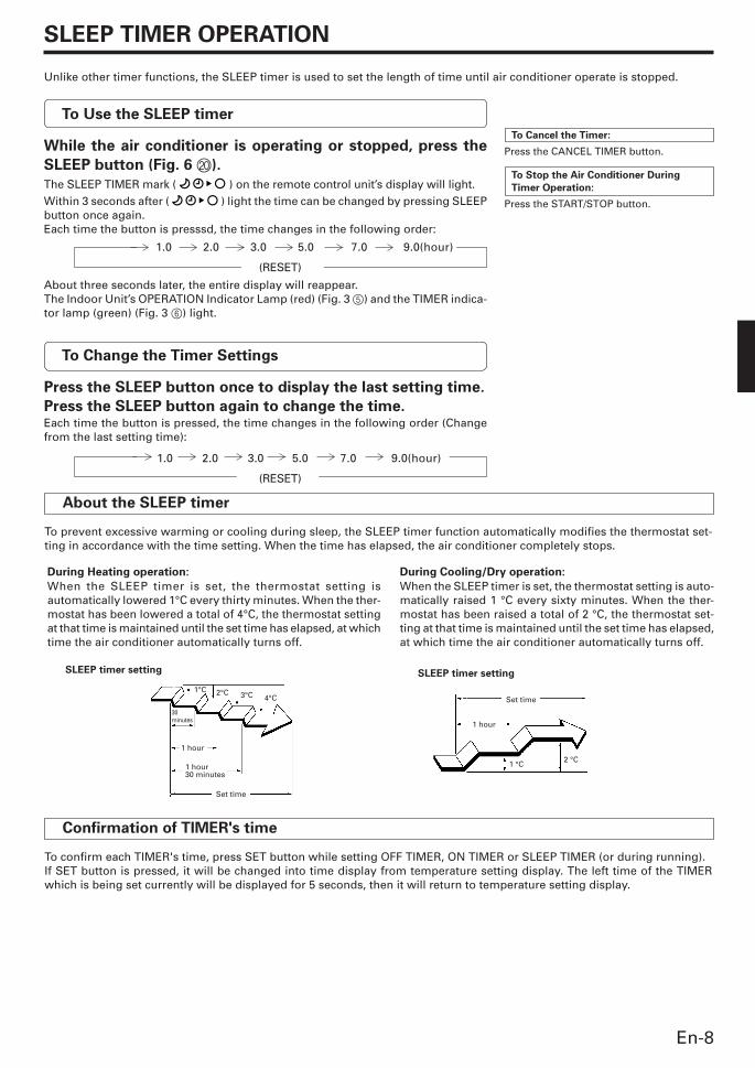
During Cooling/Dry operation:
When the SLEEP timer is set, the thermostat setting is auto-matically raised 1 °C every sixty minutes. When the ther-mostat has been raised a total of 2 °C, the thermostat set-ting at that time is maintained until the set time has elapsed,at which time the air conditioner automatically turns off.
SLEEP timer setting
2°C 3°C 4°C
30minutes
1°C
1 hour
1 hour30 minutes
Set time
Set time
1 hour
1 °C2 °C
During Heating operation:
When the SLEEP timer is set, the thermostat setting isautomatically lowered 1°C every thirty minutes. When the ther-mostat has been lowered a total of 4°C, the thermostat settingat that time is maintained until the set time has elapsed, at whichtime the air conditioner automatically turns off.
SLEEP timer setting
Confirmation of TIMER's time
To confirm each TIMER's time, press SET button while setting OFF TIMER, ON TIMER or SLEEP TIMER (or during running).If SET button is pressed, it will be changed into time display from temperature setting display. The left time of the TIMERwhich is being set currently will be displayed for 5 seconds, then it will return to temperature setting display.
1.0 2.0 3.0 5.0 7.0 9.0(hour)
(RESET)
1.0 2.0 3.0 5.0 7.0 9.0(hour)
(RESET)
9312175017-01_en.pm6.5 03.7.29, 6:48 PM8
En-9
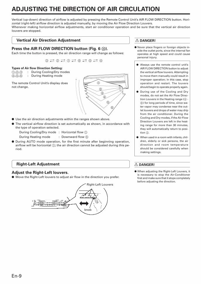
ADJUSTING THE DIRECTION OF AIR CIRCULATION
Vertical (up-down) direction of airflow is adjusted by pressing the Remote Control Unit’s AIR FLOW DIRECTION button. Hori-zontal (right-left) airflow direction is adjusted manually, by moving the Air Flow Direction Louvers.Whenever making horizontal airflow adjustments, start air conditioner operation and be sure that the vertical air directionlouvers are stopped.
R DANGER!
� Never place fingers or foreign objects in-side the outlet ports, since the internal fanoperates at high speed and could causepersonal injury.
� Always use the remote control unit’sAIR FLOW DIRECTION button to adjustthe vertical airflow louvers. Attemptingto move them manually could result inimproper operation; in this case, stopoperation and restart. The louversshould begin to operate properly again.
� During use of the Cooling and Drymodes, do not set the Air Flow Direc-tion Louvers in the Heating range (4 -6) for long periods of time, since wa-ter vapor may condense near the out-let louvers and drops of water may dripfrom the air conditioner. During theCooling and Dry modes, if the Air FlowDirection Louvers are left in the heat-ing range for more than 30 minutes,they will automatically return to posi-tion 3.
� When used in a room with infants, chil-dren, elderly or sick persons, the airdirection and room temperatureshould be considered carefully whenmaking settings.
Vertical Air Direction Adjustment
Press the AIR FLOW DIRECTION button (Fig. 6 T).Each time the button is pressed, the air direction range will change as follows:
3 2 1 6 5 4
Types of Air flow Direction Setting:
1,2,3 : During Cooling/Dry modes4,5,6 : During Heating mode
The remote Control Unit’s display doesnot change.
� Use the air direction adjustments within the ranges shown above.
� The vertical airflow direction is set automatically as shown, in accordance withthe type of operation selected.
During Cooling/Dry mode : Horizontal flow 1
During Heating mode : Downward flow 5
� During AUTO mode operation, for the first minute after beginning operation,airflow will be horizontal 1; the air direction cannot be adjusted during this pe-riod.
Right-Left Adjustment
Adjust the Right-Left louvers.� Move the Right-Left louvers to adjust air flow in the direction you prefer.
Right-Left Louvers
knob
1
2
3
4
5
6
R DANGER!
� When adjusting the Right-Left Louvers, itis necessary to stop the Air-Conditionerfirst and make sure that it stops completelybefore adjusting the direction.
9312175017-01_en.pm6.5 03.7.29, 9:33 AM9
En-10
SWING OPERATION
Begin air conditioner operation before performing this procedure.
To select SWING Operation
Press the SWING LOUVER button (Fig. 6 U).The SWING indicator lamp (orange) (Fig. 3 7) will light.In this mode, the Air Flow Direction Louvers will swing automatically to direct theair flow both up and down.
To Stop SWING Operation
Press the SWING LOUVER button (Fig. 6 U) once again.The SWING indicator lamp (orange) (Fig. 3 7) will go out.Airflow direction will return to the setting before swing was begun.
About Swing Operation
� The range of swing is relative to the currently set airflowdirection.
� During Cooling/Dry modes, if SWING Operation in con-tinued at the lowest (downward) range for more than 30minutes, the unit will automatically switch the swing rangeto the horizontal flow range, to prevent the condensationof moisture on the outlet.
MANUAL AUTO OPERATION
Use the MANUAL AUTO operation in the event the Remote Control Unit is lost or otherwise unavailable.
How To Use the Main Unit Controls
Press the MANUAL AUTO button (Fig. 2 2) on the main unit
control panel.To stop operation, press the MANUAL AUTO button once again.(Controls are located inside the Intake Grille)
� When the air conditioner is operatedwith the controls on the Main Unit, itwill operate under the same mode asthe AUTO mode selected on the Re-mote Control Unit (see page 6).
� The fan speed selected will be “AUTO”and the thermostat setting will bestandard.
� The SWING operation may stop temporarily when theair conditioner’s fan is not operating, or when operatingat very low speeds.
9312175017-01_en.pm6.5 03.7.29, 9:33 AM10
En-11
1
2 2
1
2
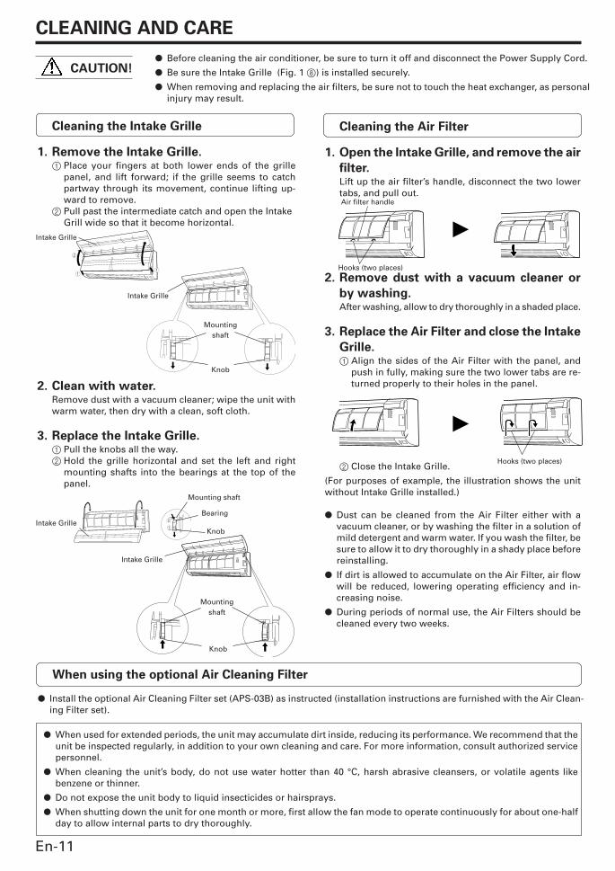
CLEANING AND CARE
CAUTION!� Before cleaning the air conditioner, be sure to turn it off and disconnect the Power Supply Cord.
� Be sure the Intake Grille (Fig. 1 8) is installed securely.
� When removing and replacing the air filters, be sure not to touch the heat exchanger, as personalinjury may result.
Cleaning the Intake Grille
1. Remove the Intake Grille.1 Place your fingers at both lower ends of the grille
panel, and lift forward; if the grille seems to catchpartway through its movement, continue lifting up-ward to remove.
2 Pull past the intermediate catch and open the IntakeGrill wide so that it become horizontal.
2. Clean with water.Remove dust with a vacuum cleaner; wipe the unit withwarm water, then dry with a clean, soft cloth.
3. Replace the Intake Grille.1 Pull the knobs all the way.2 Hold the grille horizontal and set the left and right
mounting shafts into the bearings at the top of thepanel.
Cleaning the Air Filter
1. Open the Intake Grille, and remove the air
filter.Lift up the air filter’s handle, disconnect the two lowertabs, and pull out.
2. Remove dust with a vacuum cleaner or
by washing.After washing, allow to dry thoroughly in a shaded place.
3. Replace the Air Filter and close the Intake
Grille.1 Align the sides of the Air Filter with the panel, and
push in fully, making sure the two lower tabs are re-turned properly to their holes in the panel.
2 Close the Intake Grille.
(For purposes of example, the illustration shows the unitwithout Intake Grille installed.)
� Dust can be cleaned from the Air Filter either with avacuum cleaner, or by washing the filter in a solution ofmild detergent and warm water. If you wash the filter, besure to allow it to dry thoroughly in a shady place beforereinstalling.
� If dirt is allowed to accumulate on the Air Filter, air flowwill be reduced, lowering operating efficiency and in-creasing noise.
� During periods of normal use, the Air Filters should becleaned every two weeks.
Intake Grille
Air filter handle
Hooks (two places)
Intake Grille
Hooks (two places)
When using the optional Air Cleaning Filter
� Install the optional Air Cleaning Filter set (APS-03B) as instructed (installation instructions are furnished with the Air Clean-ing Filter set).
� When used for extended periods, the unit may accumulate dirt inside, reducing its performance. We recommend that theunit be inspected regularly, in addition to your own cleaning and care. For more information, consult authorized servicepersonnel.
� When cleaning the unit’s body, do not use water hotter than 40 °C, harsh abrasive cleansers, or volatile agents likebenzene or thinner.
� Do not expose the unit body to liquid insecticides or hairsprays.
� When shutting down the unit for one month or more, first allow the fan mode to operate continuously for about one-halfday to allow internal parts to dry thoroughly.
Intake Grille
Mountingshaft
Knob
Intake Grille
Mounting shaft
Bearing
Knob
Mountingshaft
Knob
9312175017-01_en.pm6.5 03.7.29, 9:33 AM11
En-12
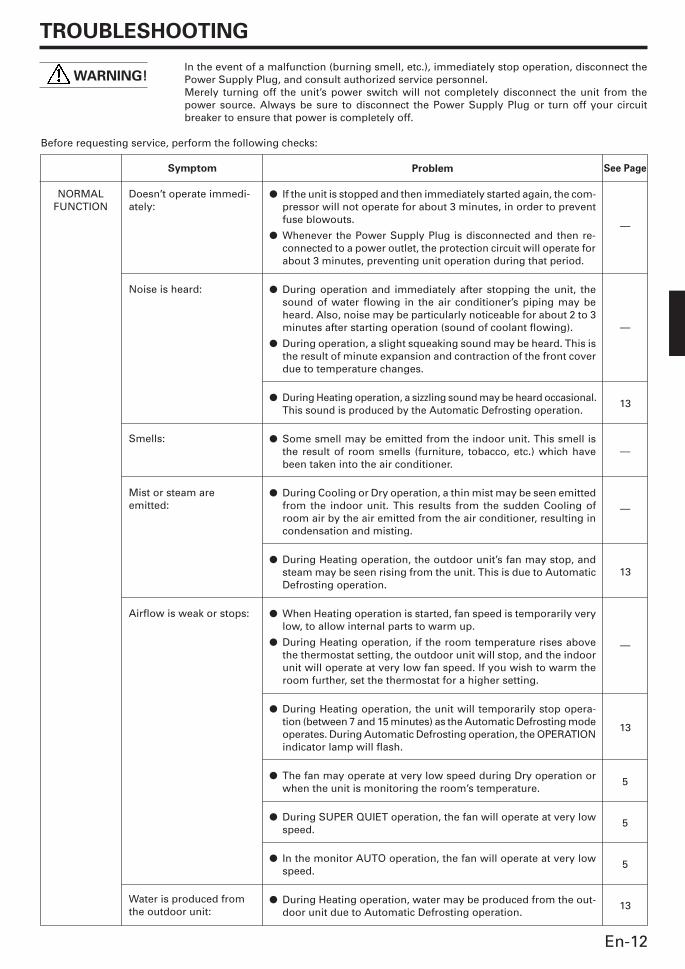
TROUBLESHOOTING
WARNING!
Symptom
Doesn’t operate immedi-ately:
Noise is heard:
Smells:
Mist or steam areemitted:
Airflow is weak or stops:
Water is produced fromthe outdoor unit:
Problem
� If the unit is stopped and then immediately started again, the com-pressor will not operate for about 3 minutes, in order to preventfuse blowouts.
� Whenever the Power Supply Plug is disconnected and then re-connected to a power outlet, the protection circuit will operate forabout 3 minutes, preventing unit operation during that period.
� During operation and immediately after stopping the unit, thesound of water flowing in the air conditioner’s piping may beheard. Also, noise may be particularly noticeable for about 2 to 3minutes after starting operation (sound of coolant flowing).
� During operation, a slight squeaking sound may be heard. This isthe result of minute expansion and contraction of the front coverdue to temperature changes.
� During Heating operation, a sizzling sound may be heard occasional.This sound is produced by the Automatic Defrosting operation.
� Some smell may be emitted from the indoor unit. This smell isthe result of room smells (furniture, tobacco, etc.) which havebeen taken into the air conditioner.
� During Cooling or Dry operation, a thin mist may be seen emittedfrom the indoor unit. This results from the sudden Cooling ofroom air by the air emitted from the air conditioner, resulting incondensation and misting.
� During Heating operation, the outdoor unit’s fan may stop, andsteam may be seen rising from the unit. This is due to AutomaticDefrosting operation.
� When Heating operation is started, fan speed is temporarily verylow, to allow internal parts to warm up.
� During Heating operation, if the room temperature rises abovethe thermostat setting, the outdoor unit will stop, and the indoorunit will operate at very low fan speed. If you wish to warm theroom further, set the thermostat for a higher setting.
� During Heating operation, the unit will temporarily stop opera-tion (between 7 and 15 minutes) as the Automatic Defrosting modeoperates. During Automatic Defrosting operation, the OPERATIONindicator lamp will flash.
� The fan may operate at very low speed during Dry operation orwhen the unit is monitoring the room’s temperature.
� During SUPER QUIET operation, the fan will operate at very lowspeed.
� In the monitor AUTO operation, the fan will operate at very lowspeed.
� During Heating operation, water may be produced from the out-door unit due to Automatic Defrosting operation.
See Page
—
—
13
—
—
13
—
13
5
5
5
13
NORMALFUNCTION
In the event of a malfunction (burning smell, etc.), immediately stop operation, disconnect thePower Supply Plug, and consult authorized service personnel.Merely turning off the unit’s power switch will not completely disconnect the unit from thepower source. Always be sure to disconnect the Power Supply Plug or turn off your circuitbreaker to ensure that power is completely off.
Before requesting service, perform the following checks:
9312175017-01_en.pm6.5 03.7.29, 9:33 AM12
En-13
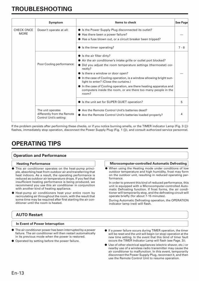
TROUBLESHOOTING
Symptom
Doesn’t operate at all:
Poor Cooling performance:
The unit operatesdifferently from the RemoteControl Unit’s setting:
See Page
—
7 - 8
—
5
4
CHECK ONCEMORE
Items to check
� Is the Power Supply Plug disconnected its outlet?
� Has there been a power failure?
� Has a fuse blown out, or a circuit breaker been tripped?
� Is the timer operating?
� Is the air filter dirty?
� Air the air conditioner’s intake grille or outlet port blocked?
� Did you adjust the room temperature settings (thermostat) cor-rectly?
� Is there a window or door open?
� In the case of Cooling operation, is a window allowing bright sun-light to enter? (Close the curtains.)
� In the case of Cooling operation, are there heating apparatus andcomputers inside the room, or are there too many people in theroom?
� Is the unit set for SUPER QUIET operation?
� Are the Remote Control Unit’s batteries dead?
� Are the Remote Control Unit’s batteries loaded properly?
OPERATING TIPS
Microcomputer-controlled Automatic Defrosting
� When using the Heating mode under conditions of lowoutdoor temperature and high humidity, frost may formon the outdoor unit, resulting in reduced operating per-formance.In order to prevent this kind of reduced performance, thisunit is equipped with a Microcomputer-controlled Auto-matic Defrosting function. If frost forms, the air condi-tioner will temporarily stop, and the defrosting circuit willoperate briefly (for about 7-15 minutes).During Automatic Defrosting operation, the OPERATIONindicator lamp (red) will flash.
Heating Performance
� This air conditioner operates on the heat-pump princi-ple, absorbing heat from outdoor air and transferring thatheat indoors. As a result, the operating performance isreduced as outdoor air temperature drops. If you feel thatinsufficient heating performance is being produced, werecommend you use this air conditioner in conjunctionwith another kind of heating appliance.
� Heat-pump air conditioners heat your entire room byrecirculating air throughout the room, with the result thatsome time may be required after first starting the air con-ditioner until the room is heated.
If the problem persists after performing these checks, or if you notice burning smells, or the TIMER indicator Lamp (Fig. 3 6)flashes, immediately stop operation, disconnect the Power Supply Plug (Fig. 1 C), and consult authorized service personnel.
Operation and Performance
AUTO Restart
In Event of Power Interruption
� The air conditioner power has been interrupted by a powerfailure. The air conditioner will then restart automaticallyin its previous mode when the power is restored.
� Operated by setting before the power failure.
� If a power failure occurs during TIMER operation, the timerwill be reset and the unit will begin (or stop) operation at thenew time setting. In the event that this (kind of timer faultoccurs the TIMER Indicator Lamp will flash (see Page. 3)).
� Use of other electrical appliances (electric shaver, etc.) ornearby use of a wireless radio transmitter may cause theair conditioner to malfunction. In this event, temporarilydisconnect the Power Supply Plug, reconnect it, and thenuse the Remote Control Unit to resume operation.
9312175017-01_en.pm6.5 03.7.29, 9:33 AM13
En-14
OPERATING TIPS
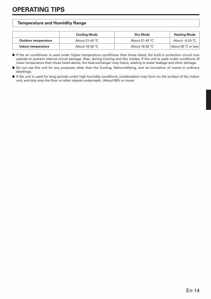
Dry Mode
About 21-43 °C
About 18-32 °C
Outdoor temperature
Indoor temperature
Cooling Mode
About 21-43 °C
About 18-32 °C
Heating Mode
About –5-24 °C
About 30 °C or less
Temperature and Humidity Range
� If the air conditioner is used under higher temperature conditioner than those listed, the built-in protection circuit mayoperate to prevent internal circuit damage. Also, during Cooling and Dry modes, if the unit is used under conditions oflower temperature than those listed above, the heat-exchanger may freeze, leading to water leakage and other damage.
� Do not use this unit for any purposes other than the Cooling, Dehumidifying, and air-circulation of rooms in ordinarydwellings.
� If the unit is used for long periods under high-humidity conditions, condensation may form on the surface of the indoorunit, and drip onto the floor or other objects underneath. (About 80% or more)
9312175017-01_en.pm6.5 03.7.29, 9:33 AM14