Κ?Q?PHCR?PQGHCO AG? QM JET?KGPJX … 84-123.pdf · Δg?pq;pcgo qmπmf
Feb. 16, 2004J-PARC NPFC 1T.Kobayashi (KEK)
Report from Report from νν--TACTACw/ recent status of neutrino facilityw/ recent status of neutrino facility
Takashi Kobayashi (KEK)
Nov.16,2003NPFC@KEK
1. Recent events (what’s new)2. Overview of facility3. Status of Design and R&D of each component4. Summary (Executive summary as conclusion)
Feb. 16, 2004J-PARC NPFC 2T.Kobayashi (KEK)
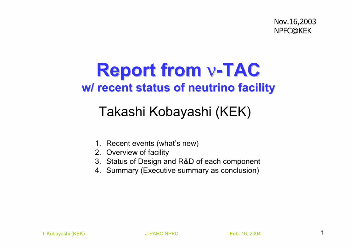
•• Nov.12,13, 2003Nov.12,13, 2003ν-TAC (technical advisory committee)
•• Dec.20,2004Dec.20,2004– Neutrino project on the draft budget from
MOF. APPROVED!APPROVED!• 5 years project from JFY2004 ~ JFY2008• First year ~ 6oku¥ (total 159.6oku¥)• Beam line + near det. @ 280m (w/o 2km det.)• Start experiment in 2009
•• Jan. 27, 2004Jan. 27, 2004ν-TAC report is submitted.
Recent eventsRecent events
Feb. 16, 2004J-PARC NPFC 3T.Kobayashi (KEK)
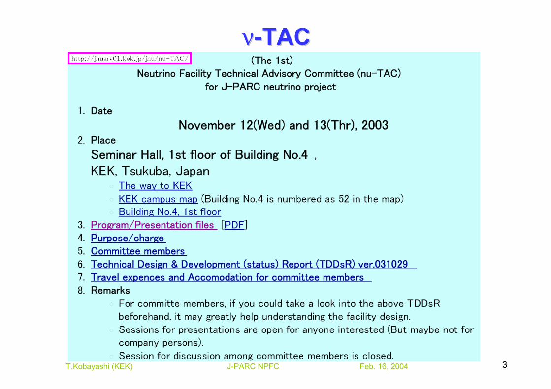
νν--TACTAC
Feb. 16, 2004J-PARC NPFC 4T.Kobayashi (KEK)
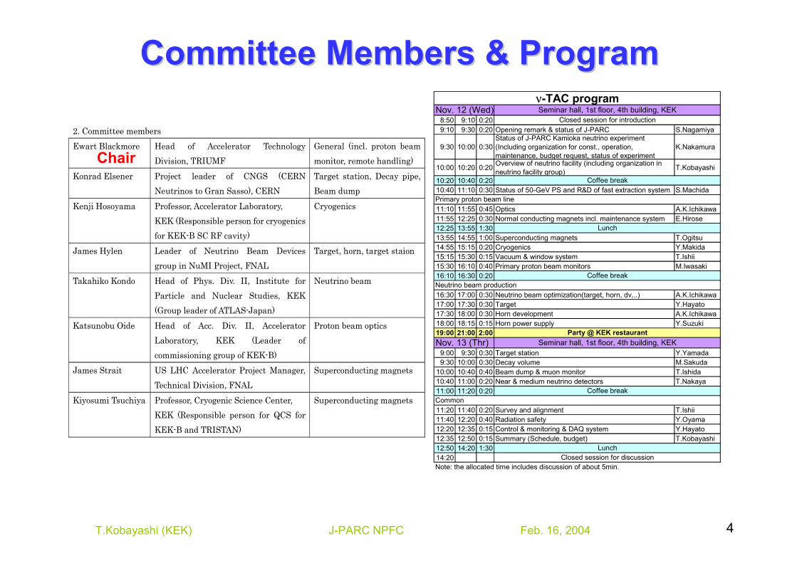
Committee Members & ProgramCommittee Members & Program
2. Committee members Ewart Blackmore Head of Accelerator Technology
Division, TRIUMF General (incl. proton beam monitor, remote handling)
Konrad Elsener Project leader of CNGS (CERN Neutrinos to Gran Sasso), CERN
Target station, Decay pipe, Beam dump
Kenji Hosoyama Professor, Accelerator Laboratory, KEK (Responsible person for cryogenics for KEK-B SC RF cavity)
Cryogenics
James Hylen Leader of Neutrino Beam Devices group in NuMI Project, FNAL
Target, horn, target staion
Takahiko Kondo Head of Phys. Div. II, Institute for Particle and Nuclear Studies, KEK (Group leader of ATLAS-Japan)
Neutrino beam
Katsunobu Oide Head of Acc. Div. II, Accelerator Laboratory, KEK (Leader of commissioning group of KEK-B)
Proton beam optics
James Strait US LHC Accelerator Project Manager, Technical Division, FNAL
Superconducting magnets
Kiyosumi Tsuchiya Professor, Cryogenic Science Center, KEK (Responsible person for QCS for KEK-B and TRISTAN)
Superconducting magnets
8:50 9:10 0:209:10 9:30 0:20 Opening remark & status of J-PARC S.Nagamiya
9:30 10:00 0:30Status of J-PARC Kamioka neutrino experiment(Including organization for const., operation,maintenance, budget request, status of experiment
K.Nakamura
10:00 10:20 0:20 Overview of neutrino facility (including organization inneutrino facility group) T.Kobayashi
10:20 10:40 0:2010:40 11:10 0:30 Status of 50-GeV PS and R&D of fast extraction system S.Machida
11:10 11:55 0:45 Optics A.K.Ichikawa11:55 12:25 0:30 Normal conducting magnets incl. maintenance system E.Hirose12:25 13:55 1:3013:55 14:55 1:00 Superconducting magnets T.Ogitsu14:55 15:15 0:20 Cryogenics Y.Makida15:15 15:30 0:15 Vacuum & window system T.Ishii15:30 16:10 0:40 Primary proton beam monitors M.Iwasaki16:10 16:30 0:20
16:30 17:00 0:30 Neutrino beam optimization(target, horn, dv,..) A.K.Ichikawa17:00 17:30 0:30 Target Y.Hayato17:30 18:00 0:30 Horn development A.K.Ichikawa18:00 18:15 0:15 Horn power supply Y.Suzuki19:00 21:00 2:00
9:00 9:30 0:30 Target station Y.Yamada9:30 10:00 0:30 Decay volume M.Sakuda
10:00 10:40 0:40 Beam dump & muon monitor T.Ishida10:40 11:00 0:20 Near & medium neutrino detectors T.Nakaya11:00 11:20 0:20
11:20 11:40 0:20 Survey and alignment T.Ishii11:40 12:20 0:40 Radiation safety Y.Oyama12:20 12:35 0:15 Control & monitoring & DAQ system Y.Hayato12:35 12:50 0:15 Summary (Schedule, budget) T.Kobayashi12:50 14:20 1:3014:20
Party @ KEK restaurant
Note: the allocated time includes discussion of about 5min.
Seminar hall, 1st floor, 4th building, KEK
Seminar hall, 1st floor, 4th building, KEK
Closed session for discussion
Nov. 13 (Thr)
Coffee break
Lunch
Common
Closed session for introduction
ν-TAC programNov. 12 (Wed)
Primary proton beam line
Neutrino beam production
Coffee break
Lunch
Coffee break
Chair
Feb. 16, 2004J-PARC NPFC 5T.Kobayashi (KEK)
OverviewOverview
Feb. 16, 2004J-PARC NPFC 6T.Kobayashi (KEK)
PV2PQ5
PQ2A
PQ4A
PH3 PQ4BPQ3B
PV1PD21.92 deg. bend
PQ3APQ2B PH1
1.9 2 deg. bend
PQ1
PD1 PH2
コン
プレ
ッサ
ー室
冷凍
機室
カー
ドル
置場
液体
窒素
タン
ク
バッファタンク
電気
室
NM1低温棟
5,800l/min(低温設備) 980l/min(磁石電源)
NM2
ヤード
~4,500l/min(磁石汚染)
トンネル空調TS換気
電気
ヤー
ド
機械ヤード
冷却棟
4%slope
保安林伐採エリア
ND1
ND2
μピ
ット
1鉄
置場
μピット
測定室
電源ヤード
DQ2
DD2
Horn1
DD1
DQ1
DD3
DQ3 DQ4
Horn2
電源室
シャ
ッタ
ー
電気室
DSV DSH
サブトンネルA
サブトンネルB
サブ
トンネ
ルC
サブ
トン
ネル
D
輸送道路レベルTP+9.3mへ。
土盛り上面はTP+10.8m保存するため法面発生。
ニュートリノ建屋を輸送道路側へ3m、8間道路から
離れる方向へ5m移動。(020207小林隆)
建屋壁面より5m離れたところまで保安林伐採。
伐採面積計:0.286haSM1 ST1
SM2ST2
ST3 ST4
UD1
UQ3
UQ1 UQ2
UV1 UV2
UH3
UH2
UQ4電源棟UQ5
UD2 UH1
制御室
出入管理
WC
WC
適当
な広
さ
37.5
m4%
slope
放射
化物
保管
室
2.4 3.63.03.6 2.4
13.5
μピ
ット1
3.0
20.0
6.6
3.0
6.6
30.0
5.65.6
3.0
4.64.6
4.57.0
3.5
15.0
5.0 5.0 5.0 μピ
ット2
2 .50
2 .00
8.00
4.00
2 .50
1.50
3.00
3.50
1. 50 1.5 0
2.00
3. 50
60.0
130.0
25,000
decay pipe
Near detector
TargetStation
µ-pit280m
130m
3NBT
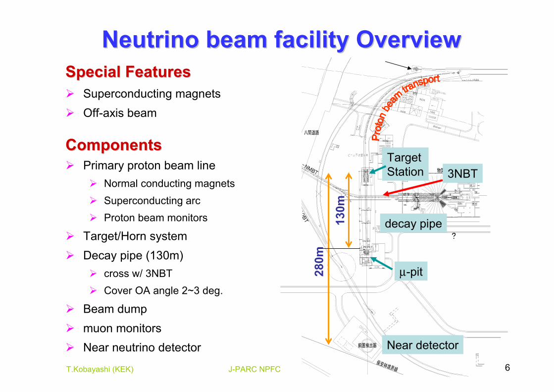
Neutrino beam facility OverviewNeutrino beam facility OverviewSpecial FeaturesSpecial Features
Superconducting magnetsOff-axis beam
ComponentsComponentsPrimary proton beam line
Normal conducting magnetsSuperconducting arcProton beam monitors
Target/Horn systemDecay pipe (130m)
cross w/ 3NBTCover OA angle 2~3 deg.
Beam dumpmuon monitorsNear neutrino detector
Feb. 16, 2004J-PARC NPFC 7T.Kobayashi (KEK)
ビーム振り下げ
FH1F
Q1
PD11.92 deg. bend
PC4PQ5 PH3
PC3 PQ3PQ4
PV2PC2 PC1
1.92 deg. bend
PD2PV1
引き出し基準点x=49615028.58, y=69561283.94
ニュートリノ・ビームライン
PQ2A PQ1
PH1PH2
サスペンション型
クレーン(20t x 2)
FV2
FQ4
FV1
FQ3
FH2
FV2
FQ2
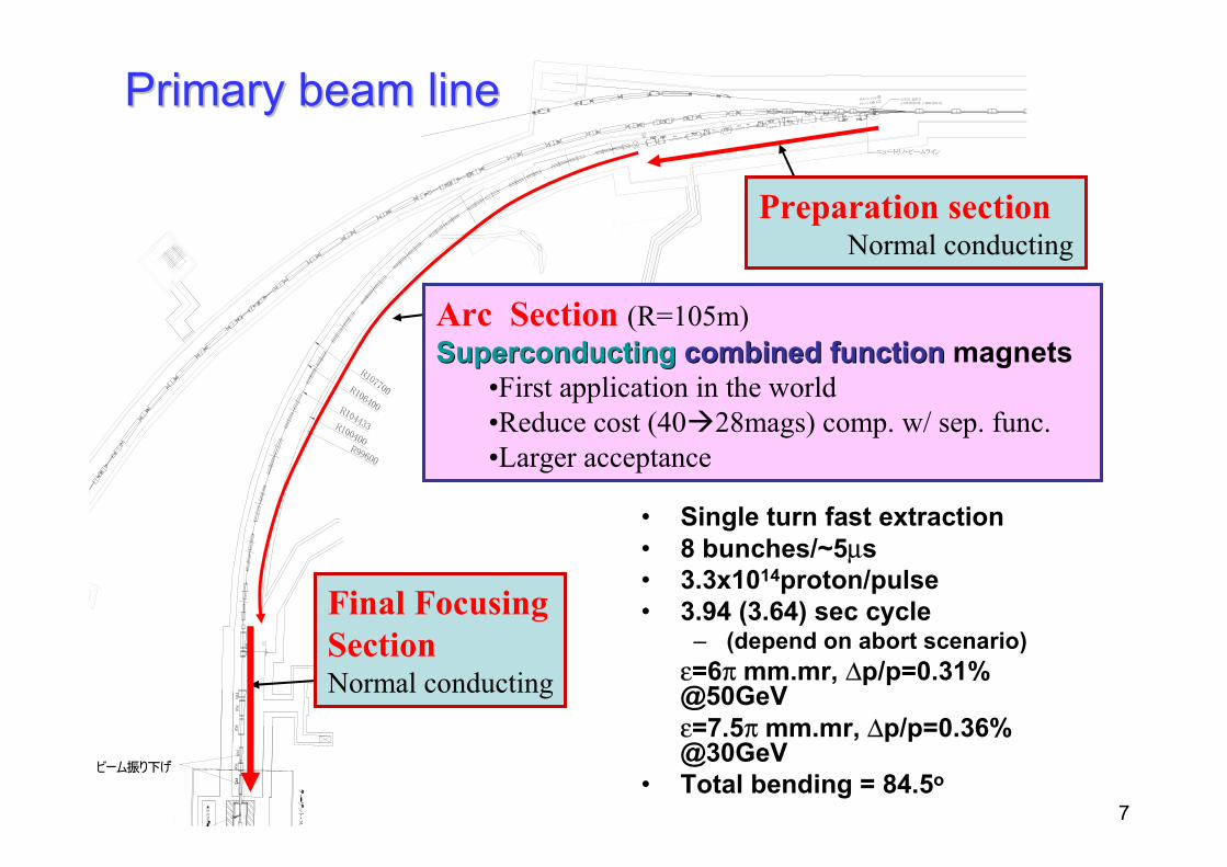
Primary beam linePrimary beam line
Preparation sectionNormal conducting
Arc Section (R=105m)SuperconductingSuperconducting combined functioncombined function magnets
•First application in the world•Reduce cost (40 28mags) comp. w/ sep. func.•Larger acceptance
Final Focusing SectionNormal conducting
• Single turn fast extraction• 8 bunches/~5µs• 3.3x10¹⁴proton/pulse• 3.94 (3.64) sec cycle
– (depend on abort scenario)ε=6π mm.mr, ∆p/p=0.31% @50GeV ε=7.5π mm.mr, ∆p/p=0.36% @30GeV
• Total bending = 84.5o
Feb. 16, 2004J-PARC NPFC 8T.Kobayashi (KEK)
FQ4
FQ3B
FQ3A
FH2
FV2
FV1
ビーム振り下げ
FQ2 B
F Q2 A
FH1
FQ1
PQ4BPH3
PV2PQ5
PV1 PQ3BPQ4A 1.92 deg. bend
PQ2B
PD2PQ3APD1
PQ1
1.92 deg. bend
PQ2A
ニュートリノ・ビームライン
PH1PH2
サスペンション型
クレーン(20t x 2)
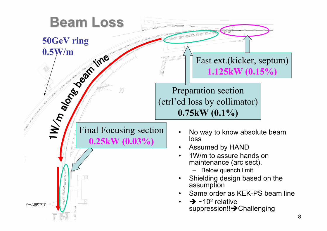
• No way to know absolute beam loss
• Assumed by HAND • 1W/m to assure hands on
maintenance (arc sect).– Below quench limit.
• Shielding design based on the assumption
• Same order as KEK-PS beam line• ~102 relative
suppression!! Challenging
Fast ext.(kicker, septum)1.125kW (0.15%)
Preparation section(ctrl’ed loss by collimator)
0.75kW (0.1%)
50GeV ring0.5W/m
Final Focusing section0.25kW (0.03%)
Beam LossBeam Loss
Feb. 16, 2004J-PARC NPFC 9T.Kobayashi (KEK)
Feb. 16, 2004J-PARC NPFC 10T.Kobayashi (KEK)
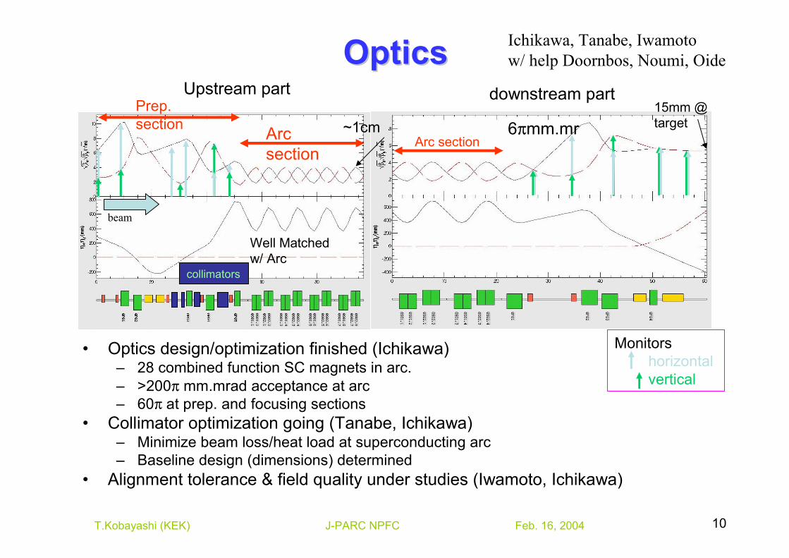
OpticsOptics
beam
Arc section
Prep. section
Well Matched w/ Arc
collimators
~1cmArc section
Monitorshorizontalvertical
15mm @ target
Upstream part
Ichikawa, Tanabe, Iwamotow/ help Doornbos, Noumi, Oide
downstream part
6πmm.mr
• Optics design/optimization finished (Ichikawa)– 28 combined function SC magnets in arc.– >200π mm.mrad acceptance at arc– 60π at prep. and focusing sections
• Collimator optimization going (Tanabe, Ichikawa)– Minimize beam loss/heat load at superconducting arc– Baseline design (dimensions) determined
• Alignment tolerance & field quality under studies (Iwamoto, Ichikawa)
Feb. 16, 2004J-PARC NPFC 11T.Kobayashi (KEK)
Recommendations: OpticsRecommendations: Optics• The design of the beam optics of the proton beam line looks
quite reasonable, showing that the use of combined function magnets is quite feasible. No fatal flaw or difficulties were found in the design.
• There should be better interaction between the 50 GeV main ring group and the neutrino facility design group to specify the extracted beam emittance and expected profiles (beam tails, halos etc).
• The tolerances of the beam parameters (orbit, Twiss, etc.) at the target must be specified considering the neutrino performance, the heating of the target and the dump by the proton component, etc. A strategy of the orbit/optics correction must be shown to achieve such tolerances under possible machine errors including errors in the ring.
Feb. 16, 2004J-PARC NPFC 12T.Kobayashi (KEK)
Superconducting Superconducting magnetsmagnets
Feb. 16, 2004J-PARC NPFC 13T.Kobayashi (KEK)
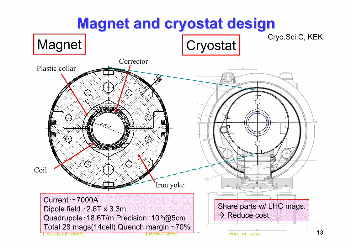
Coil
Iron yoke
Plastic collarCorrector
Magnet Cryostat
Current:~7000ADipole field :2.6T x 3.3mQuadrupole:18.6T/m Precision: 10-3@5cmTotal 28 mags(14cell) Quench margin ~70%
Share parts w/ LHC mags.Reduce cost
Magnet and cryostat designMagnet and cryostat designCryo.Sci.C, KEK
Feb. 16, 2004J-PARC NPFC 14T.Kobayashi (KEK)
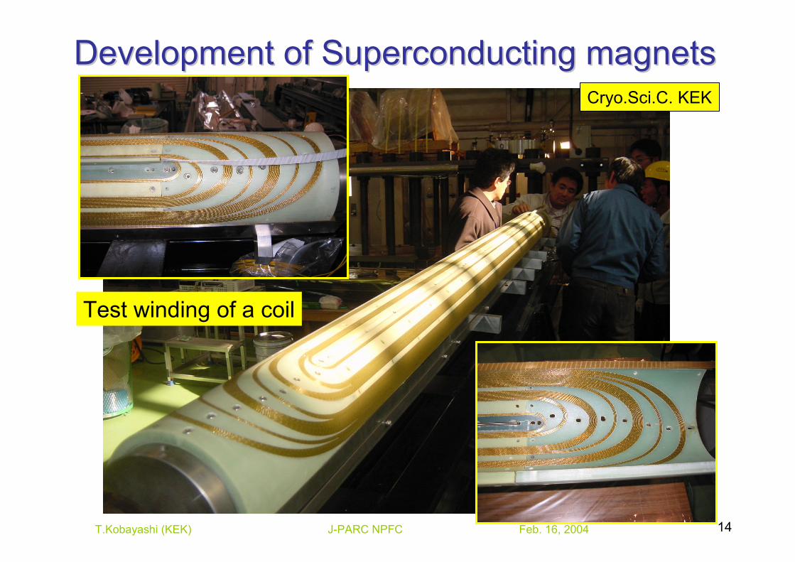
Development of Superconducting magnetsDevelopment of Superconducting magnets
Test winding of a coil
Cryo.Sci.C. KEK
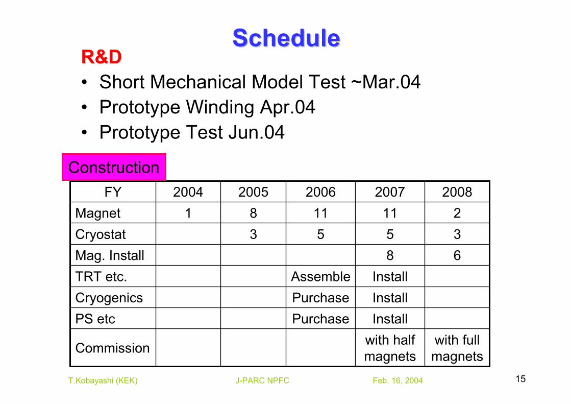
Feb. 16, 2004J-PARC NPFC 15T.Kobayashi (KEK)
with full magnets
with half magnetsCommission
InstallAssembleTRT etc.
InstallPurchasePS etcInstallPurchaseCryogenics
68Mag. Install3553Cryostat2111181Magnet
20082007200620052004FY
ScheduleSchedule
Construction
R&DR&D• Short Mechanical Model Test ~Mar.04• Prototype Winding Apr.04• Prototype Test Jun.04
Feb. 16, 2004J-PARC NPFC 16T.Kobayashi (KEK)
Recommendations: Superconducting Recommendations: Superconducting magnetsmagnets
• Build and test the prototype as soon as possible, which contains sufficient instrumentation to be able to determine the cause of any performance issues.
• Make a plan that will allow rapid construction of a second prototype, if necessary, that includes design modifications that address problems found in the first prototype.
• Do the beam studies necessary to determine the required set of correction magnets and prototype them as early as possible.
• As part of a study of the overall beam vacuum system, consider eliminating the inner beam tubeand using the cold bore tube as the beam tube.
Feb. 16, 2004J-PARC NPFC 17T.Kobayashi (KEK)
CryogenicsCryogenics
Feb. 16, 2004J-PARC NPFC 18T.Kobayashi (KEK)
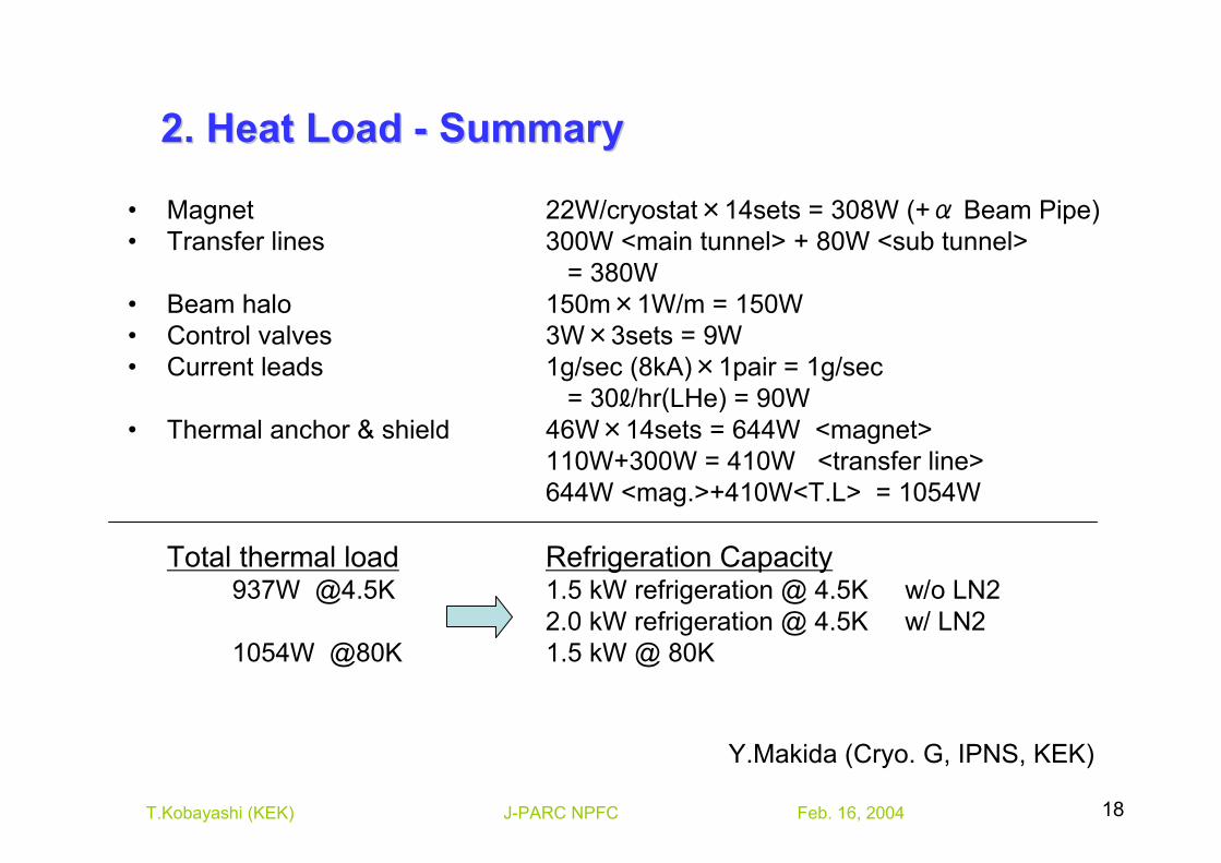
2. Heat Load 2. Heat Load -- SummarySummary
• Magnet 22W/cryostat×14sets = 308W (+α Beam Pipe)• Transfer lines 300W <main tunnel> + 80W <sub tunnel>
= 380W• Beam halo 150m×1W/m = 150W• Control valves 3W×3sets = 9W• Current leads 1g/sec (8kA)×1pair = 1g/sec
= 30ℓ/hr(LHe) = 90W• Thermal anchor & shield 46W×14sets = 644W <magnet>
110W+300W = 410W <transfer line>644W <mag.>+410W<T.L> = 1054W
Total thermal load Refrigeration Capacity937W @4.5K 1.5 kW refrigeration @ 4.5K w/o LN2
2.0 kW refrigeration @ 4.5K w/ LN2 1054W @80K 1.5 kW @ 80K
Y.Makida (Cryo. G, IPNS, KEK)
Feb. 16, 2004J-PARC NPFC 19T.Kobayashi (KEK)
Col
d Bo
x
Purif
ier
10m
UH1
UQ3UQ2UQ1
ST2SM1 ST1
UQ5 UH3
UH2
UQ4
ST4ST3
SM2
UD1UV2UV1
UD2
Buffe
r Tan
k
Buffe
r Tan
k
Evac
uatio
nPu
mp
Power Supplies
Utilities
Mai
n C
ompr
esso
r
Oil
Sepa
rato
rUtilitiy Yard
Que
nch
Buffe
r
Que
nch
Buffe
rPower Utilities
Tube
Tra
iler
Gas
War
mer
LN2
Tank
PS
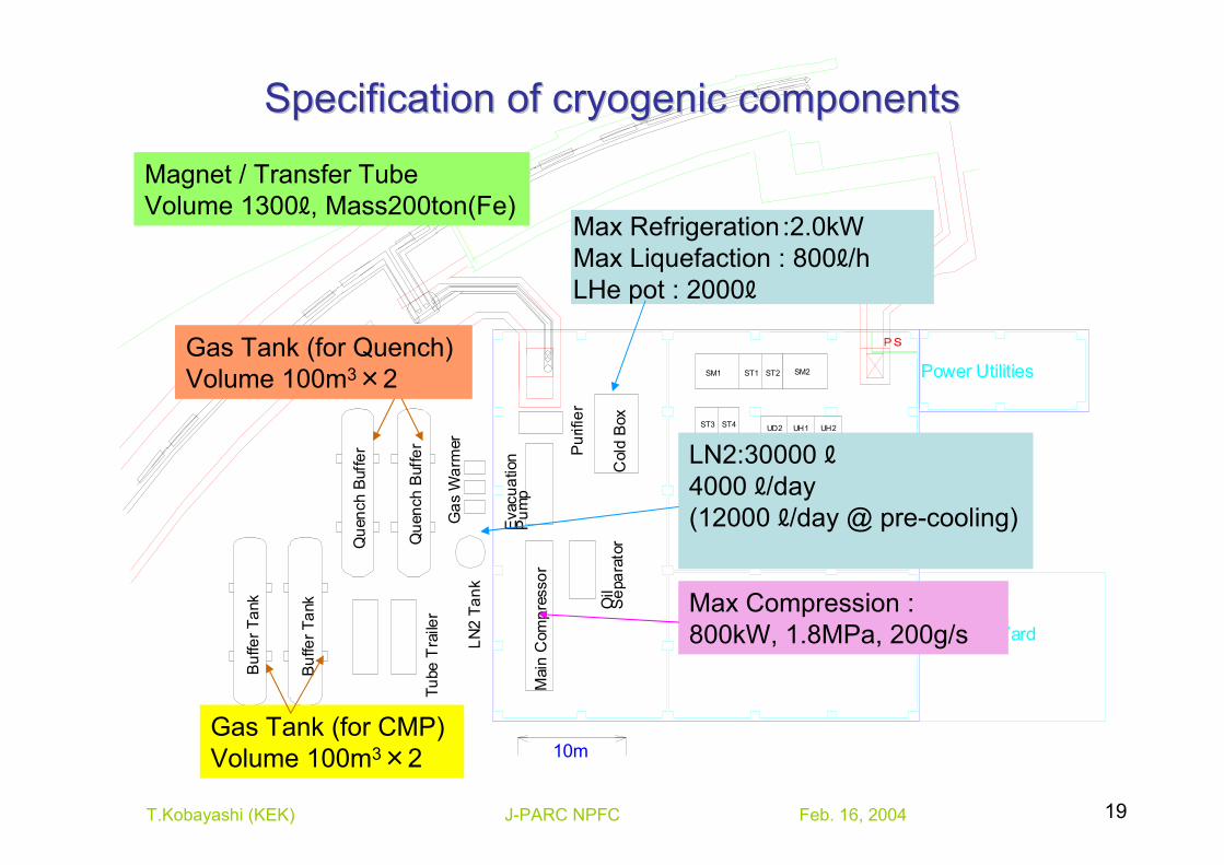
Max Refrigeration:2.0kWMax Liquefaction : 800ℓ/hLHe pot : 2000ℓ
Max Compression : 800kW, 1.8MPa, 200g/s
Gas Tank (for CMP)Volume 100m3×2
Gas Tank (for Quench)Volume 100m3×2
LN2:30000 ℓ4000 ℓ/day (12000 ℓ/day @ pre-cooling)
Gas Tank (for Quench)Volume 100m3×2
Magnet / Transfer TubeVolume 1300ℓ, Mass200ton(Fe)
Specification of cryogenic componentsSpecification of cryogenic components
Feb. 16, 2004J-PARC NPFC 20T.Kobayashi (KEK)
Recommendations: CryogenicsRecommendations: Cryogenics
• The heat load as calculated appears to be very conservative. More effort should be made to reduce the heart load and therefore the size and cost of the refrigeration system.
Feb. 16, 2004J-PARC NPFC 21T.Kobayashi (KEK)
Normal Normal conducting conducting
magnetsmagnets
Feb. 16, 2004J-PARC NPFC 22T.Kobayashi (KEK)
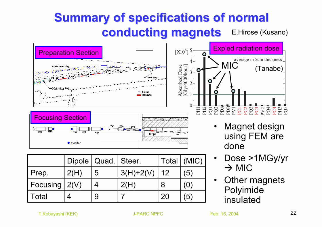
Summary of specifications of normal Summary of specifications of normal conducting magnetsconducting magnets E.Hirose (Kusano)
(5)(0)(5)(MIC)
20812Total
794Total2(H)3(H)+2(V)Steer.
42(V)Focusing52(H)Prep.Quad.Dipole
0
1
2
3
4
5[X106]
Abs
orbe
d D
ose
[Gly
/400
0hou
r]
PH1
PH2
PQ1
PQ2
PDA
PDB
PV1
PC1
PC2
PQ3
PV2
PC3
PQ4
PC4
PH3
PQ5
average in 5cm thickness
(Tanabe)MIC
• Magnet design using FEM are done
• Dose >1MGy/yr MIC
• Other magnets Polyimide insulated
Exp’ed radiation dosePreparation Section
Focusing Section
Feb. 16, 2004J-PARC NPFC 23T.Kobayashi (KEK)
空調ダクト
300
700
5000
600
1000
900
7000
?250
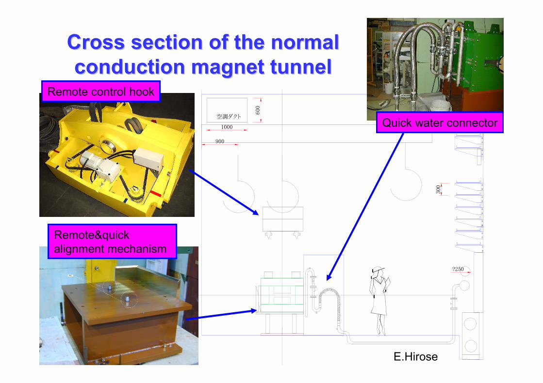
Cross section of the normal Cross section of the normal conduction magnet tunnelconduction magnet tunnel
E.Hirose
Remote control hook
Remote&quickalignment mechanism
Quick water connector
Feb. 16, 2004J-PARC NPFC 24T.Kobayashi (KEK)
Recommendations: Normal conducting Recommendations: Normal conducting magnetsmagnets
• The number of beam line magnets that have to be made radiation hard should be carefully assessed after better knowledge of beam halos is obtained from the accelerator group and included in the optics design.
Feb. 16, 2004J-PARC NPFC 25T.Kobayashi (KEK)
Beam Beam monitorsmonitors
Feb. 16, 2004 J-PARC NPFC 26
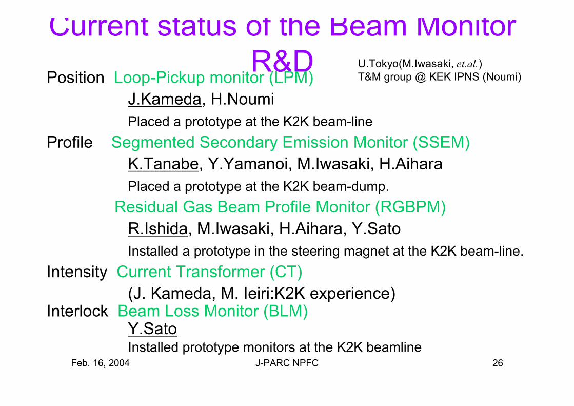
Current status of the Beam Monitor R&D
Position Loop-Pickup monitor (LPM)J.Kameda, H.NoumiPlaced a prototype at the K2K beam-line
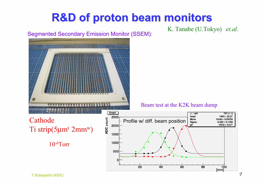
Profile Segmented Secondary Emission Monitor (SSEM)K.Tanabe, Y.Yamanoi, M.Iwasaki, H.AiharaPlaced a prototype at the K2K beam-dump.
Residual Gas Beam Profile Monitor (RGBPM)R.Ishida, M.Iwasaki, H.Aihara, Y.SatoInstalled a prototype in the steering magnet at the K2K beam-line.
Intensity Current Transformer (CT)(J. Kameda, M. Ieiri:K2K experience)
Interlock Beam Loss Monitor (BLM)Y.SatoInstalled prototype monitors at the K2K beamline
U.Tokyo(M.Iwasaki, et.al.)T&M group @ KEK IPNS (Noumi)
Feb. 16, 2004J-PARC NPFC 27T.Kobayashi (KEK)
Beam test at the K2K beam dump
10-6Torr
K. Tanabe (U.Tokyo) et.al.
Cathode Ti strip(5µmt 2mmw)
R&D of proton beam monitorsR&D of proton beam monitorsSegmented Secondary Emission Monitor (SSEM):
Profile w/ diff. beam position
Feb. 16, 2004J-PARC NPFC 28T.Kobayashi (KEK)
Recommendations: Beam monitorsRecommendations: Beam monitors
• The group should try to make use of existing monitor designs wherever possible.
• There should be careful engineering of the monitors that must be installed in the high radiation areas for reliability and serviceability.
Feb. 16, 2004J-PARC NPFC 29T.Kobayashi (KEK)
VacuumVacuum
Feb. 16, 2004J-PARC NPFC 30T.Kobayashi (KEK)
PV2PQ5
PQ2A
PQ4A
PH3 PQ4BPQ3B
PV1PD21. 92 de g. bend
PQ3APQ2B PH1
1. 92 de g. bend
PQ1
PD1 PH2
サブトンネルA
サブトンネルB
サブ
トンネ
ルC
サブ
トン
ネル
D
放射
化物
保管
室
60.0
Preparation Section (PS)
ARC Section
Final Focusing Section (FF)
Target Station (TS)
PS vacuum window (?)
50GeV ring
Emergency valve15m
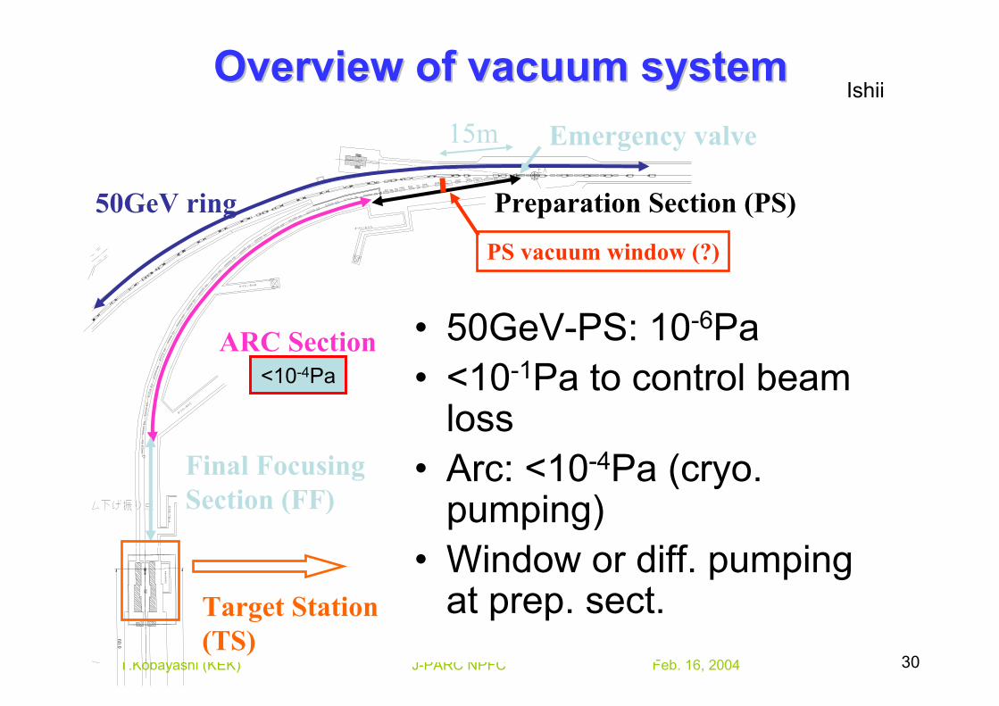
Overview of vacuum systemOverview of vacuum systemIshii
<10-4Pa
• 50GeV-PS: 10-6Pa• <10-1Pa to control beam
loss• Arc: <10-4Pa (cryo.
pumping)• Window or diff. pumping
at prep. sect.
Feb. 16, 2004J-PARC NPFC 31T.Kobayashi (KEK)
Recommendations: VacuumRecommendations: Vacuum
• The baseline design should be made with no vacuum window separating the main ring from the proton beam line. This reduces potential beam spill loss into beam line components and makes it unnecessary to carefully monitor the beam size at this window location.
Feb. 16, 2004J-PARC NPFC 32T.Kobayashi (KEK)
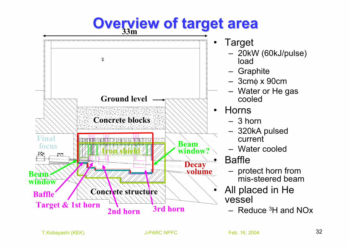
Overview of target areaOverview of target area33m
Iron shield
Concrete blocks
Target & 1st horn
Beam window
2nd horn 3rd horn
Final focus
Decay volume
Concrete structure
Beam window?
Ground level
Baffle
• Target– 20kW (60kJ/pulse)
load– Graphite– 3cmφ x 90cm– Water or He gas
cooled• Horns
– 3 horn– 320kA pulsed
current– Water cooled
• Baffle– protect horn from
mis-steered beam• All placed in He
vessel– Reduce 3H and NOx
Feb. 16, 2004J-PARC NPFC 33T.Kobayashi (KEK)
Target Target StationStation
Feb. 16, 2004J-PARC NPFC 34T.Kobayashi (KEK)
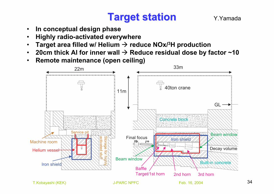
Target stationTarget station• In conceptual design phase• Highly radio-activated everywhere• Target area filled w/ Helium reduce NOx/3H production• 20cm thick Al for inner wall Reduce residual dose by factor ~10• Remote maintenance (open ceiling)
Iron shield
Helium vessel
Machine room
Service pit
Sto
rage fo
r hig
hly
activ
ate
d s
tuff
Iron shield
Concrete block
Target/1st horn
Beam window
2nd horn 3rd horn
Final focus
Decay volume
Built-in concrete
Beam window
Baffle
22m 33m
11m40ton crane
GL
Y.Yamada
Feb. 16, 2004J-PARC NPFC 35T.Kobayashi (KEK)
Recommendations: Target StationRecommendations: Target Station
• Check possible effect of enhanced horn electrical breakdown from the use of helium atmosphere.
• Make a layout in the machine room of all of the equipment that will be needed to determine if there is enough space.
Feb. 16, 2004J-PARC NPFC 36T.Kobayashi (KEK)
TargetTarget
Feb. 16, 2004J-PARC NPFC 37T.Kobayashi (KEK)
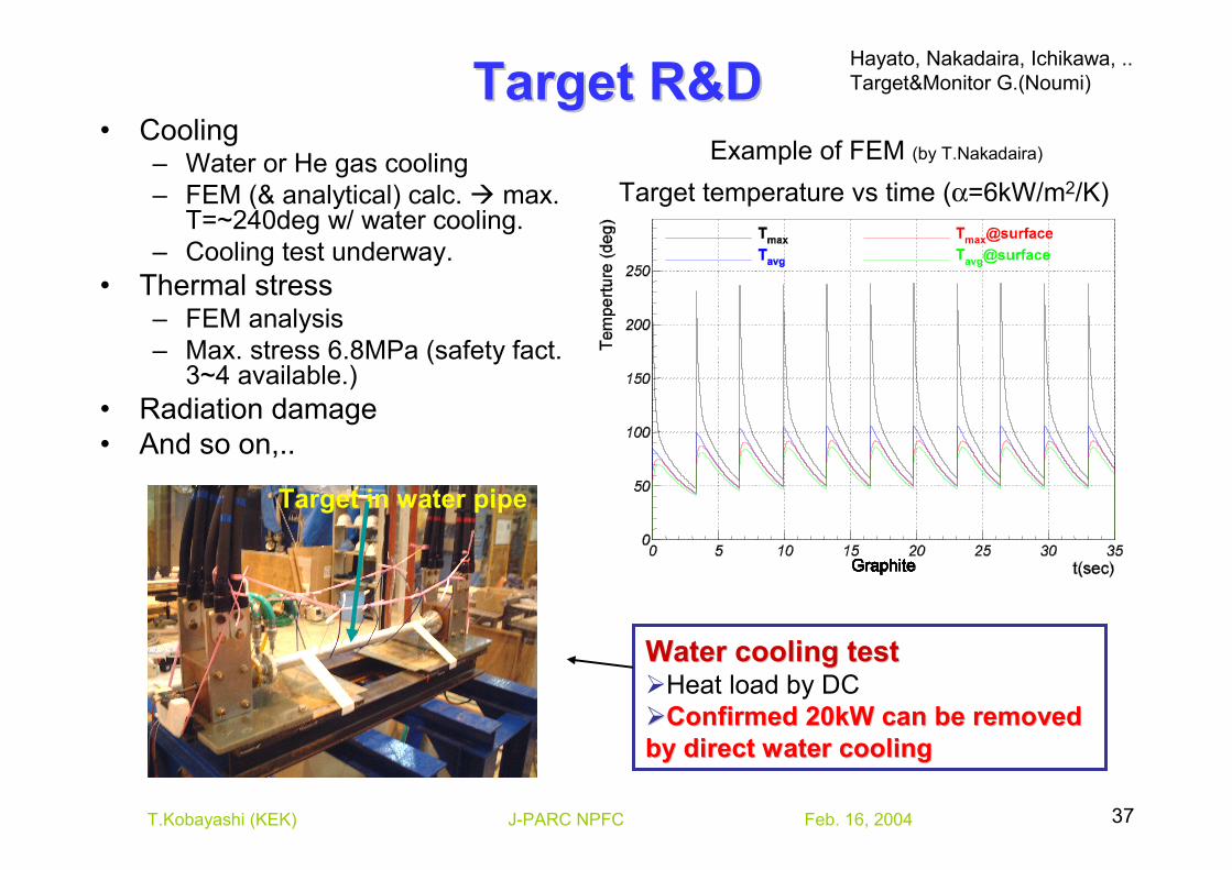
Target R&DTarget R&D• Cooling
– Water or He gas cooling– FEM (& analytical) calc. max.
T=~240deg w/ water cooling.– Cooling test underway.
• Thermal stress– FEM analysis– Max. stress 6.8MPa (safety fact.
3~4 available.)• Radiation damage• And so on,..
Target temperature vs time (α=6kW/m2/K)Example of FEM (by T.Nakadaira)
Water cooling testWater cooling testHeat load by DCConfirmed 20kW can be removed Confirmed 20kW can be removed
by direct water coolingby direct water cooling
Target in water pipe
Hayato, Nakadaira, Ichikawa, ..Target&Monitor G.(Noumi)
Feb. 16, 2004J-PARC NPFC 38T.Kobayashi (KEK)
Recommendations: TargetRecommendations: Target
• Determine whether the target water jacket also needs to be protected by the baffle and whether the baffle needs to be water-cooled.
Feb. 16, 2004J-PARC NPFC 39T.Kobayashi (KEK)
HornHorn
Feb. 16, 2004J-PARC NPFC 40T.Kobayashi (KEK)
100 cm100 cm
900472
2500
1400
2000
809
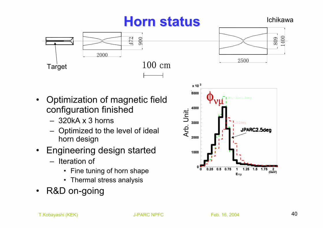
Horn statusHorn status
Target
φφνµνµ
Arb
. Uni
t.
Ichikawa
• Optimization of magnetic field configuration finished– 320kA x 3 horns– Optimized to the level of ideal
horn design• Engineering design started
– Iteration of• Fine tuning of horn shape• Thermal stress analysis
• R&D on-going
Feb. 16, 2004J-PARC NPFC 41T.Kobayashi (KEK)
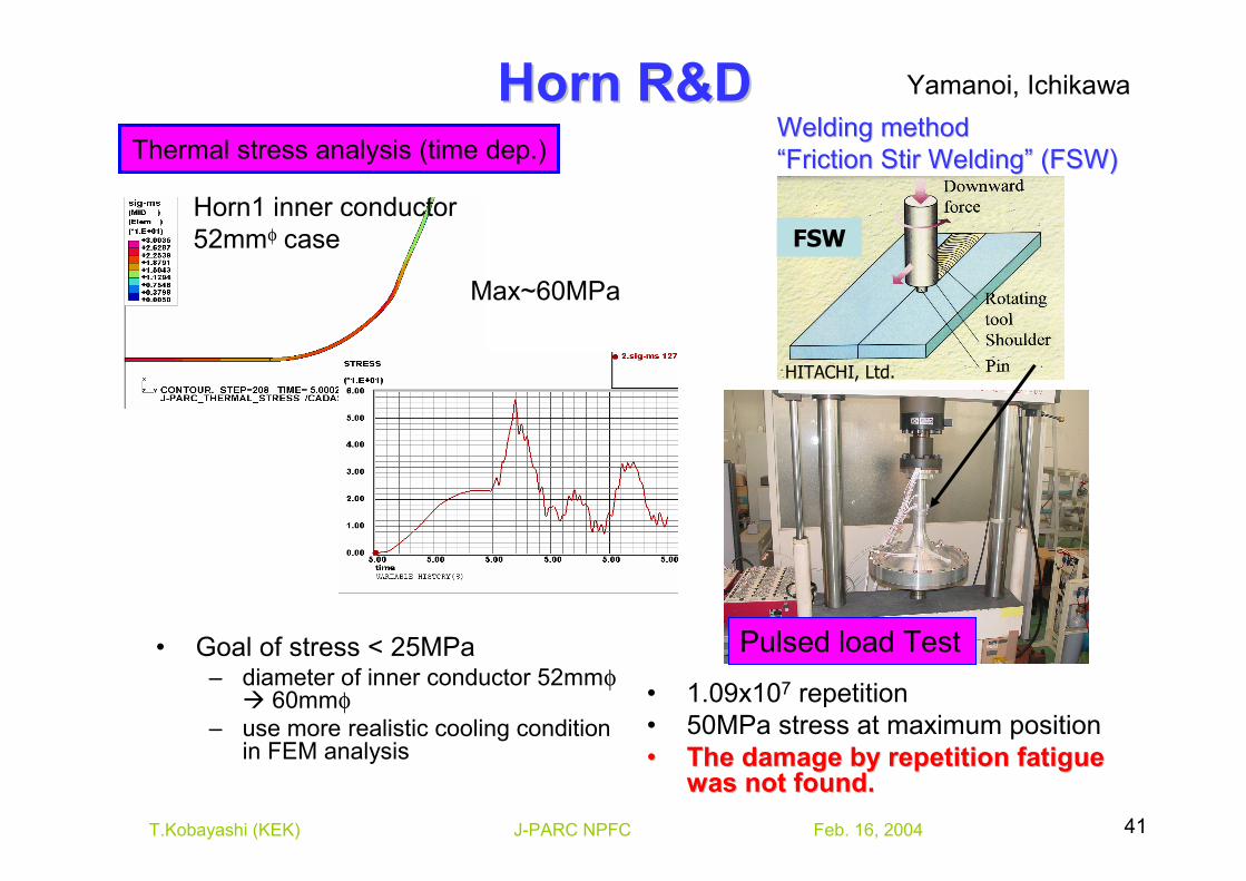
Horn R&DHorn R&D
• Goal of stress < 25MPa– diameter of inner conductor 52mmφ
60mmφ– use more realistic cooling condition
in FEM analysis
• 1.09x10⁷ repetition• 50MPa stress at maximum position•• The damage by repetition fatigue The damage by repetition fatigue
was not found.was not found.
Pulsed load Test
FSW
HITACHI, Ltd.
Welding methodWelding method““Friction Stir WeldingFriction Stir Welding”” (FSW)(FSW)
Horn1 inner conductor52mmφ case
Max~60MPa
Thermal stress analysis (time dep.)
Yamanoi, Ichikawa
Feb. 16, 2004J-PARC NPFC 42T.Kobayashi (KEK)
Recommendations: HornsRecommendations: Horns
• The design group should compare an optimized two horn beam to the proposed three horn beam to demonstrate what the gain is with horn material included.
• A specification for horn construction tolerances should be documented, based on physics systematic error concerns.
Feb. 16, 2004J-PARC NPFC 43T.Kobayashi (KEK)
Decay Decay volumevolume
Feb. 16, 2004J-PARC NPFC 44T.Kobayashi (KEK)
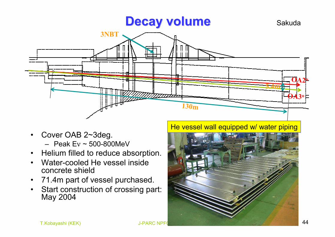
Decay volumeDecay volume
• Cover OAB 2~3deg.– Peak Eν ~ 500-800MeV
• Helium filled to reduce absorption.• Water-cooled He vessel inside
concrete shield• 71.4m part of vessel purchased.• Start construction of crossing part:
May 2004
3NBT
130m
5.4mOA2o
OA3o
He vessel wall equipped w/ water piping
Sakuda
Feb. 16, 2004J-PARC NPFC 45T.Kobayashi (KEK)
Recommendations: Decay VolumeRecommendations: Decay Volume• Although there is a slightly higher cost, there must be as
many independent water-cooling loops as possible. The safety margin in the water-cooling capacity must allow to close off some of the cooling loops in the event of leaks.
• It would be preferable to be able to fill helium in the decay volume without pumping the volume (i.e. by flushing –reduces risks for the entrance/exit windows and risk of the volume buckling under vacuum).
• Since the water cooling circuits are located on the inside of the decay volume, a scheme for (a) detecting a water leak (b) emptying the water at the bottom end of the decay volume (c) storing the radioactive water in a tank near the hadron stop area (etc.) needs to be developed.
• The design of the exit flange must be robust enough to withstand a few "shots" of the full 4 MW beam. In particular, water-cooling pipes must be placed outside the range, which is potentially hit by a (possibly mis-steered) proton beam.
Feb. 16, 2004J-PARC NPFC 46T.Kobayashi (KEK)
Dump & Dump & muon muon
monitormonitor
Feb. 16, 2004J-PARC NPFC 47T.Kobayashi (KEK)
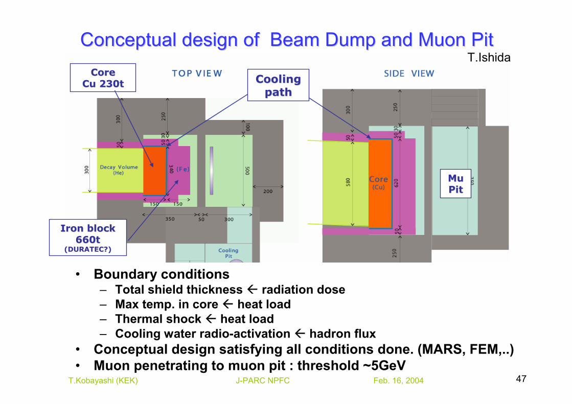
Conceptual design of Beam Dump and Muon PitConceptual design of Beam Dump and Muon Pit
Cooling Cooling pathpath
MuMuPitPit
Iron block Iron block 660t660t
(DURATEC?)(DURATEC?)
CoreCoreCu 230tCu 230t
• Boundary conditions– Total shield thickness radiation dose– Max temp. in core heat load– Thermal shock heat load– Cooling water radio-activation hadron flux
• Conceptual design satisfying all conditions done. (MARS, FEM,..)• Muon penetrating to muon pit : threshold ~5GeV
T.Ishida
Feb. 16, 2004J-PARC NPFC 48T.Kobayashi (KEK)
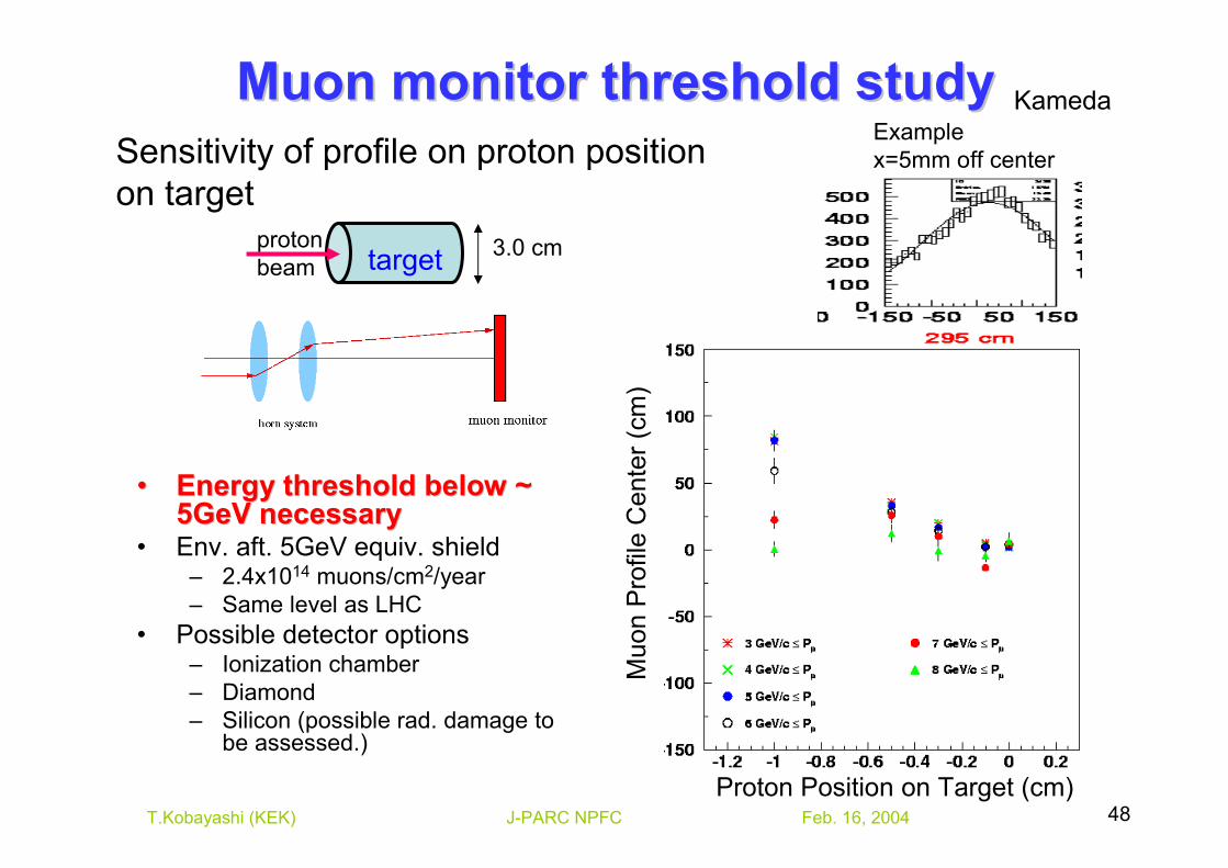
3.0 cmtargetproton beam
Muon monitor threshold study Muon monitor threshold study
•• Energy threshold below ~ Energy threshold below ~ 5GeV necessary5GeV necessary
• Env. aft. 5GeV equiv. shield– 2.4x10¹⁴ muons/cm2/year– Same level as LHC
• Possible detector options– Ionization chamber– Diamond– Silicon (possible rad. damage to
be assessed.)
Examplex=5mm off center
Proton Position on Target (cm)
Muo
n P
rofil
e C
ente
r (cm
)
Sensitivity of profile on proton position on target
Kameda
Feb. 16, 2004J-PARC NPFC 49T.Kobayashi (KEK)
Recommendations: Beam dump & Muon Recommendations: Beam dump & Muon monitoringmonitoring
• Extra space should be reserved in the beam dump / muon monitor cavern to allow for an evolution in the design of the beam dump (aluminium or graphite instead of or together with copper).
• Independent cooling loops in the beam dump water-cooling system must ensure that there is enough cooling capacity even if several loops have to be closed off due to leaks.
• Muon monitors should be built based on robust, existing technology such as ionisation monitors. R&D efforts for muon monitors are to be avoided.
Feb. 16, 2004J-PARC NPFC 50T.Kobayashi (KEK)
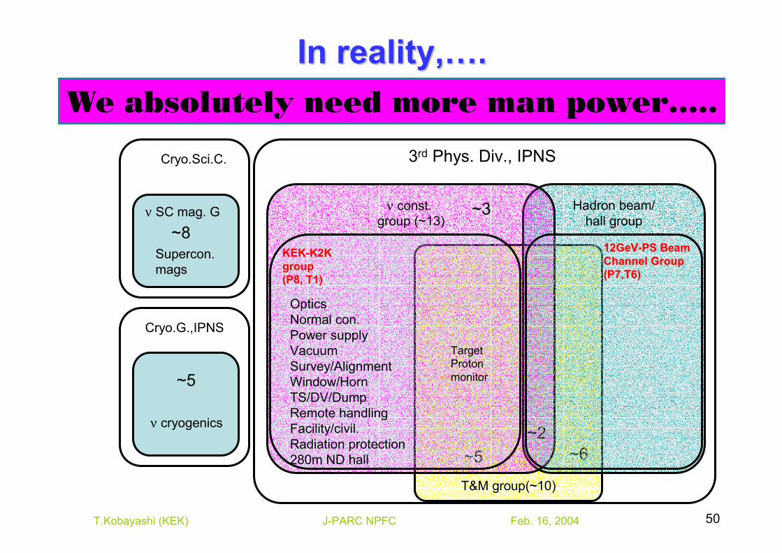
T&M group(~10)
Hadron beam/hall group
ν const. group (~13)
In reality,In reality,……..
~2~5 ~6
3rd Phys. Div., IPNS
~3
KEKKEK--K2KK2Kgroupgroup(P8, T1)(P8, T1)
12GeV12GeV--PS Beam PS Beam Channel GroupChannel Group(P7,T6)(P7,T6)
Cryo.Sci.C.
ν SC mag. G
Cryo.G.,IPNS
OpticsNormal con.Power supplyVacuumSurvey/AlignmentWindow/HornTS/DV/DumpRemote handlingFacility/civil.Radiation protection280m ND hall
TargetProtonmonitor
Supercon.mags
ν cryogenics
~8
~5
We absolutely need more man power…..
Feb. 16, 2004J-PARC NPFC 51T.Kobayashi (KEK)
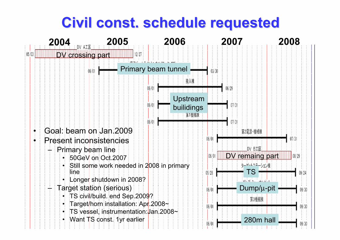
Civil const. schedule requestedCivil const. schedule requested2004 2005 2006 2007 2008
DV crossing part
Primary beam tunnel
Upstreambuilidings
DV remaing part
TS
Dump/µ-pit
280m hall
• Goal: beam on Jan.2009• Present inconsistencies
– Primary beam line• 50GeV on Oct.2007• Still some work needed in 2008 in primary
line• Longer shutdown in 2008?
– Target station (serious)• TS civil/build. end Sep.2009?• Target/horn installation: Apr.2008~• TS vessel, instrumentation:Jan.2008~• Want TS const. 1yr earlier
Feb. 16, 2004J-PARC NPFC 52T.Kobayashi (KEK)
Recommendations: Radiation & Safety Recommendations: Radiation & Safety IssuesIssues
• Further studies should be carried out to determine the optimum configuration of shielding to permit access to the proton beam tunnel during commissioning and operation of the 50 GeV main ring (without fast extraction).
Feb. 16, 2004J-PARC NPFC 53T.Kobayashi (KEK)
Recommendations: ScheduleRecommendations: Schedule
• The construction of the target hall should be advanced by one year to allow sufficient time for the installation of the target/horn components and the checkout of the remote handling methods.
Feb. 16, 2004J-PARC NPFC 54T.Kobayashi (KEK)
Possible contribution from abroadPossible contribution from abroad• Jan.11,12,2004 “T2K” collaboration meeting
– Discussed mainly on possibilities of foreign contributions• Normal conducting magnets
– Russia,…• Superconducting magnet
– LHC parts: Europe– Corrector : US(BNL,SUNY-SB)
• Cryogenics– Europe
• Proton beam monitors– TRIUMF, Saclay, RAL,…
• Remote maintenance system– TRIUMF, Saclay, RAL, …
• 280m detector– Almost all institutions
Feb. 16, 2004J-PARC NPFC 55T.Kobayashi (KEK)
Executive summary Executive summary (as conclusion)(as conclusion)
• The committee feels that there are no “show stoppers” in terms of meeting the design goals for 0.75 MW operation.
• A time frame of 5 years for the completion of the neutrino facility is a realistic goal.
• more people (even if only available part-time) with expertise in accelerator design, beam instrumentation, ………. must be assigned to the project.
• One design constraint that has already been established is the repetition rate of the 50 GeV ring, with a cycle time of 3.53 s (2.83 s if the standby state is removed). This leads to a rather high intensity of 3.3 x 10¹⁴ protons/pulse for 0.75 MW operation and presents some interesting design challenges in handling the thermal shock from the beam. The design group has made good progress in solving the beam intensity issues for this power level.
• Support from the KEK Director and from the J-PARC Project Directorwill be required to ensure that the necessary resources are applied to make this project a success.
• Another area where improved cooperation seems to be required is between the 50 GeV accelerator group and the neutrino facility construction group.
Feb. 16, 2004J-PARC NPFC 56T.Kobayashi (KEK)
Proposal to make Proposal to make νν--tactac as standingas standing• Neutrino facility is now one of the largest projects
in J-PARC (~160M$)• J-PARC neutrino experiment is really international
project (12 countries)• Neutrino beam line is the critical component for the
success of the experiment.• The neutrino facility design, development and
construction must be open internationally and be exposed under regular critical reviews to ensure success.
• Place to answer advices and home works we got from the committee
![Sapthaham May 2014 - Narayanalayam · Hmw \tam \mcm-b-Wmb Om Namo Narayanaya 2014 sabv 25 apX¬ Pq¨ 1 hsc 25 May - 1 June, 2014 \mcmbWmebw \t√∏n≈n, ]me°mSv - -678 553- - …](https://static.fdocument.org/doc/165x107/5b5d636a7f8b9ad2198e3a3c/sapthaham-may-2014-hmw-tam-mcm-b-wmb-om-namo-narayanaya-2014-sabv-25-apx.jpg)