R-SPL (SAFETY PLUS™) – High performance expansion … FIXINGS/RAWLPLUG TCHNICAL … · HIGH...
4
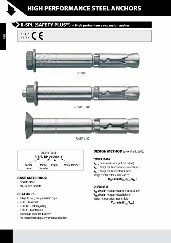
HIGH PERFORMANCE STEEL ANCHORS R-SPL (SAFETY PLUS™) – High performance expansion anchor BASE MATERIALS: • concrete, stone • non-cracked concrete FEATURES: • 8.8 grade steel, zinc-plated min. 5 μm • R-SPL – Loosebolt • R-SPL-BP – Bolt Projecting • R-SPL-C – Countersunk • Wide range of anchor diameter • The most demanding safety critical applications PRODUCT CODE R-SPL-BP-08095/15 anchor name length thread diameter fixture thickness R-SPL R-SPL-BP R-SPL-C DESIGN METHOD (according to ETAG) TENSILE LOADS N Rd,p : Design resistance (pull out failure) N Rd,c : Design resistance (concrete cone failure) N Rd,s : Design resistance (steel failure) Design resistance for tensile load is: N Rd = min (N Rd,p ,N Rd,c ,N Rd,s ) SHEAR LOADS V Rd,c : Design resistance (concrete edge failure) V Rd,s : Design resistance (steel failure) Design resistance for shear loads is: V Rd = min (V Rd,c ,V Rd,s ) R-SPL
Transcript of R-SPL (SAFETY PLUS™) – High performance expansion … FIXINGS/RAWLPLUG TCHNICAL … · HIGH...
HIGH PERFORMANCE STEEL ANCHORS
R-SPL (SAFETY PLUS™) – High performance expansion anchor
BASE MATERIALS:• concrete,stone• non-crackedconcrete
FEATURES:• 8.8gradesteel,zinc-platedmin.5μm• R-SPL–Loosebolt• R-SPL-BP–BoltProjecting• R-SPL-C–Countersunk• Widerangeofanchordiameter• Themostdemandingsafetycriticalapplications
PRODUCTCODER-SPL-BP-08095/15
anchorname
lengththreaddiameter
fixturethickness
R-SPL
R-SPL-BP
R-SPL-C
DESIGN METHOD (according to ETAG)
TENSILE LOADSNRd,p:Designresistance(pulloutfailure)NRd,c:Designresistance(concreteconefailure)NRd,s:Designresistance(steelfailure)Designresistancefortensileloadis:
NRd= min (NRd,p,NRd,c,NRd,s)
SHEAR LOADSVRd,c:Designresistance(concreteedgefailure)VRd,s:Designresistance(steelfailure)Designresistanceforshearloadsis:
VRd= min (VRd,c,VRd,s)
R-SPL
HIGH PERFORMANCE STEEL ANCHORS
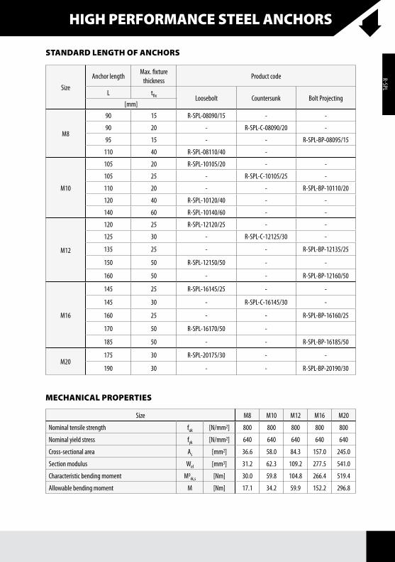
STANDARD LENGTH OF ANCHORS
Size
AnchorlengthMax.fixturethickness
Productcode
L tfix Loosebolt Countersunk BoltProjecting[mm]
M8
90 15 R-SPL-08090/15 - -
90 20 - R-SPL-C-08090/20 -
95 15 - - R-SPL-BP-08095/15
110 40 R-SPL-08110/40 -
M10
105 20 R-SPL-10105/20 - -
105 25 - R-SPL-C-10105/25 -
110 20 - - R-SPL-BP-10110/20
120 40 R-SPL-10120/40 - -
140 60 R-SPL-10140/60 - -
M12
120 25 R-SPL-12120/25 - -
125 30 - R-SPL-C-12125/30 -
135 25 - - R-SPL-BP-12135/25
150 50 R-SPL-12150/50 - -
160 50 - - R-SPL-BP-12160/50
M16
145 25 R-SPL-16145/25 - -
145 30 - R-SPL-C-16145/30 -
160 25 - - R-SPL-BP-16160/25
170 50 R-SPL-16170/50 -
185 50 - - R-SPL-BP-16185/50
M20175 30 R-SPL-20175/30 - -
190 30 - - R-SPL-BP-20190/30
MECHANICAL PROPERTIES
Size M8 M10 M12 M16 M20
Nominaltensilestrength fuk [N/mm2] 800 800 800 800 800
Nominalyieldstress fyk [N/mm2] 640 640 640 640 640
Cross-sectionalarea As [mm2] 36.6 58.0 84.3 157.0 245.0
Sectionmodulus Wel [mm3] 31.2 62.3 109.2 277.5 541.0
Characteristicbendingmoment M0rk,s [Nm] 30.0 59.8 104.8 266.4 519.4
Allowablebendingmoment M [Nm] 17.1 34.2 59.9 152.2 296.8
R-SPL
HIGH PERFORMANCE STEEL ANCHORS
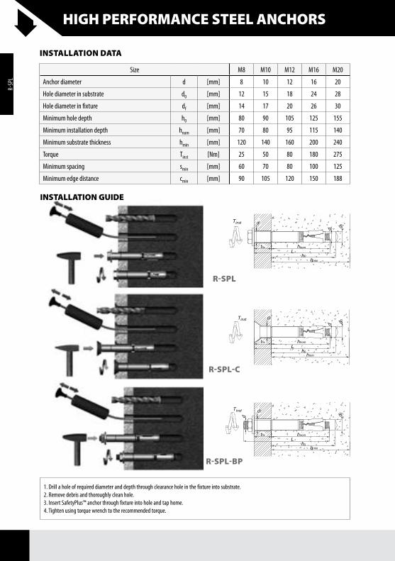
INSTALLATION GUIDE
1.Drillaholeofrequireddiameteranddepththroughclearanceholeinthefixtureintosubstrate.2.Removedebrisandthoroughlycleanhole.3.InsertSafetyPlus™anchorthroughfixtureintoholeandtaphome.4.Tightenusingtorquewrenchtotherecommendedtorque.
INSTALLATION DATA
Size M8 M10 M12 M16 M20
Anchordiameter d [mm] 8 10 12 16 20
Holediameterinsubstrate d0 [mm] 12 15 18 24 28
Holediameterinfixture df [mm] 14 17 20 26 30
Minimumholedepth h0 [mm] 80 90 105 125 155
Minimuminstallationdepth hnom [mm] 70 80 95 115 140
Minimumsubstratethickness hmin [mm] 120 140 160 200 240
Torque Tinst [Nm] 25 50 80 180 275
Minimumspacing smin [mm] 60 70 80 100 125
Minimumedgedistance cmin [mm] 90 105 120 150 188
R-SPL
R-SPL-BP
R-SPL-C
R-SPL
HIGH PERFORMANCE STEEL ANCHORS
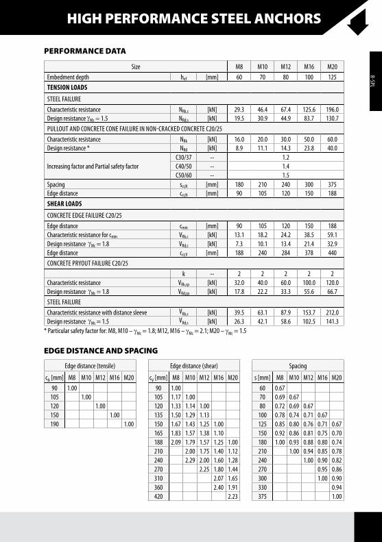
Size M8 M10 M12 M16 M20Embedmentdepth hef [mm] 60 70 80 100 125TENSION LOADS
STEELfAILURECharacteristicresistance NRk,s [kN] 29.3 46.4 67.4 125.6 196.0DesignresistancegMs=1.5 NRd,s [kN] 19.5 30.9 44.9 83.7 130.7PULLOUTANDCONCRETECONEfAILUREINNON-CRACkEDCONCRETEC20/25Characteristicresistance NRk [kN] 16.0 20.0 30.0 50.0 60.0Designresistance* NRd [kN] 8.9 11.1 14.3 23.8 40.0
IncreasingfactorandPartialsafetyfactorC30/37 -- 1.2C40/50 -- 1.4C50/60 -- 1.5
Spacing scr,N [mm] 180 210 240 300 375Edgedistance ccr,N [mm] 90 105 120 150 188SHEAR LOADS
CONCRETEEDgEfAILUREC20/25Edgedistance cmin [mm] 90 105 120 150 188Characteristicresistanceforcmin VRk,c [kN] 13.1 18.2 24.2 38.5 59.1DesignresistancegMc=1.8 VRd,c [kN] 7.3 10.1 13.4 21.4 32.9Edgedistance ccr,V [mm] 188 240 284 378 440CONCRETEPRyOUTfAILUREC20/25
k -- 2 2 2 2 2Characteristicresistance VRk,cp [kN] 32.0 40.0 60.0 100.0 120.0DesignresistancegMc=1.8 VRd,cp [kN] 17.8 22.2 33.3 55.6 66.7STEELfAILURECharacteristicresistancewithdistancesleeve VRk,s [kN] 39.5 63.1 87.9 153.7 212.0DesignresistancegMs=1.5 VRd,s [kN] 26.3 42.1 58.6 102.5 141.3
PERFORMANCE DATA
*Particularsafetyfactorfor:M8,M10–gMc=1.8;M12,M16–gMc=2.1;M20–gMc=1.5
EDGE DISTANCE AND SPACING
Edgedistance(tensile)
cN[mm] M8 M10 M12 M16 M2090 1.00 105 1.00 120 1.00 150 1.00 190 1.00
Edgedistance(shear)
cV[mm] M8 M10 M12 M16 M2090 1.00 105 1.17 1.00 120 1.33 1.14 1.00 135 1.50 1.29 1.13 150 1.67 1.43 1.25 1.00 165 1.83 1.57 1.38 1.10 188 2.09 1.79 1.57 1.25 1.00210 2.00 1.75 1.40 1.12240 2.29 2.00 1.60 1.28270 2.25 1.80 1.44310 2.07 1.65360 2.40 1.91420 2.23
Spacing
s[mm] M8 M10 M12 M16 M2060 0.67 70 0.69 0.67 80 0.72 0.69 0.67 100 0.78 0.74 0.71 0.67 125 0.85 0.80 0.76 0.71 0.67150 0.92 0.86 0.81 0.75 0.70180 1.00 0.93 0.88 0.80 0.74210 1.00 0.94 0.85 0.78240 1.00 0.90 0.82270 0.95 0.86300 1.00 0.90330 0.94375 1.00
R-SPL