Questions on Kinematics
18
Questions on Kinematics 1. Annulas Mapping Consider the annular 2-D body Ω = {(X 1 ,X 2 ) | 1 < p X 2 1 + X 2 2 < 2}. Draw the deformed body associated with the following motion. u r = u · e r =0.4 * (R - 1) 2 cos(3Θ) u θ = u · e θ =0.4 * (R - 1) 3 Note: 1. R = p X 2 1 + X 2 2 and Θ = tan -1 [X 2 /X 1 ] are simply the polar coordinates of a point. 2. e r and e θ are the unit orthonormal base vectors in polar coordinates. e r = cos(θ)e 1 + sin(θ)e 2 and e θ = - sin(θ)e 1 + cos(θ)e 2 . 3. Don’t do this by hand! Use a computer. 2. Rectangle Mapping Given the 2-D body Ω = {(X 1 ,X 2 ) | 0.1 <X 1 < 1 , 0.1 <X 2 < 1} and the displacement field u 1 = u · e 1 =0.2 * ln(1 + X 1 + X 2 ) (1) u 2 = u · e 2 =0.2 * exp(X 1 ) (2) plot the displaced shape of the body. Hand made plots are not acceptable for this question. Use a computer. 3. Displacement Mapping Given the 2-D body Ω = {(X 1 ,X 2 ) | 0.1 <X 1 < 1 , 0.1 < X 2 < 1} and the displacement field u r = u · e r =0.2 * exp(X 1 ) (3) u θ = u · e θ =0.2 * ln(1 + X 1 + X 2 ) (4) plot the displaced shape of the body. 4. Deformed Curve Consider a curve in an undeformed body that is given by c(s) ∈ R 3 for s ∈ [0, 1]; i.e. c : [0, 1] → R 3 . Recall that the expression for the length of this curve is given by l(c)= R 1 0 k d ds c(s)k ds. Assume c(s)= " √ 3 2 cos(sπ)+1 # e 1 + 1 2 cos(sπ)+2 e 2 + sin(πs)e 3 (a) Determine the length of the curve. (b) Assume the body is deformed by a pure shear motion such that x = X + X 2 e 1 . Determine the length of the deformed curve. Express your answer to at least 3 significant digits. [Note that you may need to use an approximation technique to get your final answer.]
Transcript of Questions on Kinematics
Questions on Kinematics
1. Annulas Mapping Consider the annular 2-D body Ω = (X1, X2) | 1 <√X2
1 +X22 <
2. Draw the deformed body associated with the following motion.
ur = u · er = 0.4 ∗ (R− 1)2 cos(3Θ)
uθ = u · eθ = 0.4 ∗ (R− 1)3
Note:
1. R =√X2
1 +X22 and Θ = tan−1[X2/X1] are simply the polar coordinates of a point.
2. er and eθ are the unit orthonormal base vectors in polar coordinates. er =cos(θ)e1 + sin(θ)e2 and eθ = − sin(θ)e1 + cos(θ)e2.
3. Don’t do this by hand! Use a computer.
2. Rectangle Mapping Given the 2-D body Ω = (X1, X2) | 0.1 < X1 < 1 , 0.1 < X2 <1 and the displacement field
u1 = u · e1 = 0.2 ∗ ln(1 +X1 +X2) (1)
u2 = u · e2 = 0.2 ∗ exp(X1) (2)
plot the displaced shape of the body.
Hand made plots are not acceptable for this question. Use a computer.
3. Displacement Mapping Given the 2-D body Ω = (X1, X2) | 0.1 < X1 < 1 , 0.1 <X2 < 1 and the displacement field
ur = u · er = 0.2 ∗ exp(X1) (3)
uθ = u · eθ = 0.2 ∗ ln(1 +X1 +X2) (4)
plot the displaced shape of the body.
4. Deformed Curve Consider a curve in an undeformed body that is given by c(s) ∈ R3
for s ∈ [0, 1]; i.e. c : [0, 1]→ R3. Recall that the expression for the length of this curve
is given by l(c) =∫ 1
0‖ ddsc(s)‖ ds. Assume
c(s) =
[√3
2cos(sπ) + 1
]e1 +
[1
2cos(sπ) + 2
]e2 + sin(πs)e3
(a) Determine the length of the curve.
(b) Assume the body is deformed by a pure shear motion such that x = X + X2e1.Determine the length of the deformed curve. Express your answer to at least 3 significantdigits. [Note that you may need to use an approximation technique to get your finalanswer.]
5. Deformed Curve The motion of a body is given by:
x1 = 4X1 − 3(X2 − 2) (8)
x2 = X31 (9)
x3 = X3 . (10)
Consider the line joining the points (1, 1, 0) and (2, 2, 0) in the undeformed configura-tion of the body and compute its length in the deformed configuration. Note that theline becomes a curve when the motion occurs! You may evaluate any integrals usingnumerical integration; however, answers must be accurate to at least 3 significant digit.
6. Deformed Curve For the motion in Problem 25, consider a vertical line scored onthe outer surface of the rod from bottom to top in the reference configuration. Assumethat θ(X3) = αX3, where α is a given constant and determine the length of the “line”after the torsional motion is imposed on the rod. Note the “line” is now a curve. [Hint:Consider the original line as a bunch of short vectors and think about how each mapsinto the spatial configuration in order to generate a useful expression for finding thelength in the deformed configuration.]
7. Deformed Curve Consider a 2-dimensional body B = (X1, X2) | 0 ≤ X1 ≤ L and −h/2 ≤ X2 ≤ h/2. The motion of the body is described by the mapping:
x = χ(X) =L
2π
(1− 3
5hX2
)cos
[2πX1
L
]e1 + sin
[2πX1
L
]e2
.
Determine the length of the material line C = (X1, X2) | X2 = h/2 after deformation– i.e. the length of Ct.
8. Deformed Curve Consider a round rod of radius R and length L. The rod has a helicalscratch cut into its outer surface of the form L(s) = R cos(2πs)e1 +R sin(2πs)e2 + pse3
for s ∈ [0, Lp], where the coordinate frame is centered at the base of the rod, with the
three direction pointing along the rod’s central axis, and p is a given parameter (thepitch of the helix).
1. Show that the length of the helix is L√
4π2(R/p)2 + 1 by integrating the norm of
the curve’s tangent vector, viz.∫ L/p
0‖dL/ds‖ ds.
2. Assume the rod is now deformed by a homogenous deformation with deformationgradient F = (1/
√λ)e1 ⊗ e1 + (1/
√λ)e2 ⊗ e2 + λe3 ⊗ e3, where λ is a given
parameter. What is the new length of the helix?
3. At what value of λ does the helix reach a minimal length?
9. Strain Measures Let χi(X) = KXAδiA where the constant K ∈ R , K > 0. Find F ,C, and E.
10. Analysis of Motion For the deformation map x1 = X1, x2 = X2 +kX21 , x3 = X3, find:
Page 2
1. The deformation gradient.
2. The stretch at (1, 1, 1) in the direction oriented along the vector (1, 2, 3). [Warning!Normalize!]
3. The strain at this point in the (1, 0, 0) direction.
4. The orthogonal shear at this point between the two direction (1/√
2, 1/√
2, 0) and(−1/
√2, 1/√
2, 0).
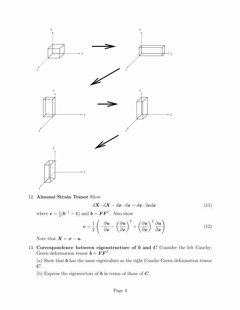
11. Composite Motion Consider the homogeneous deformation of a cube with side lengtha which is composed: first of stretching in the 1-, 2-, and 3-directions of magnitudes 1,5, and 2, respectively; followed by a +π/2 rotation about the 1-axis; followed by a +π/2rotation about the 3-axis; and then a rigid translation in the 1-direction of magnitudea. (See the accompanying figure).
1. What is the deformation gradient for this motion?
2. What happens to the (material) tangent vectors which were aligned in the ei di-rections after deformation?
3. What is the deformation mapping for this motion?
Page 3
1
2
3
1
2
3
1
2
3
1
2
3
1
2
3
12. Almansi Strain Tensor Show
dX · dX − dx · dx = dx · 2edx (11)
where e = 12(b−1 − 1) and b = FF T . Also show
e =1
2
(−∂u∂x−(∂u
∂x
)T+
(∂u
∂x
)T∂u
∂x
)(12)
Note that X = x− u.
13. Correspondence between eigenstructure of b and C Consider the left Cauchy-Green deformation tensor b = FF T .
(a) Show that b has the same eigenvalues as the right Cauchy-Green deformation tensorC.
(b) Express the eigenvectors of b in terms of those of C.
Page 4
14. Correspondence between eigenstructure of C and E Prove that the Green-Lagrange strain tensor, E, and the right Cauchy-Green strain tensor, C, have the sameeigenvectors. Find the relationship between the eigenvalues of E and C.
15. Adjugate Derivation Prove JF−T (A×B) = FA× FB.
16. Torsional Motion The torsional motion of a right circular cylinder can be approximatedas
φ→
X1 cos(βX3) +X2 sin(βX3)−X1 sin(βX3) +X2 cos(βX3)
X3
(25)
where X3 is the axial coordinate of the cylinder and β is the twist rate of the cylinder(a constant). Find F , C, and E.
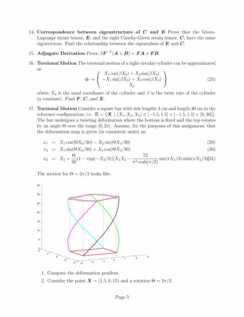
17. Torsional Motion Consider a square bar with side lengths 3 cm and length 30 cm in thereference configuration; i.e. R = X | (X1, X2, X3) ∈ [−1.5, 1.5]× [−1.5, 1.5]× [0, 30].The bar undergoes a twisting deformation where the bottom is fixed and the top rotatesby an angle Θ over the range [0, 2π]. Assume, for the purposes of this assignment, thatthe deformation map is given (in consistent units) as:
x1 = X1 cos(ΘX3/30)−X2 sin(ΘX3/30) (29)
x2 = X1 sin(ΘX3/30) +X2 cos(ΘX3/30) (30)
x3 = X3 +Θ
30(1− exp(−X3/3))[X1X2 −
72
π3 cosh(π/2)sin(πX1/3) sinh(πX2/3)](31)
The motion for Θ = 2π/3 looks like:
−3 −2 −1 0 1 2 3
−4−2
02
40
5
10
15
20
25
30
35
1. Compute the deformation gradient.
2. Consider the point X = (1.5, 0, 15) and a rotation Θ = 2π/3
Page 5
(a) What are the components of F at this point?
(b) What are the components of C at this point?
(c) What are the components of U at this point?
(d) What are the components of R at this point?
(e) Consider a triad of local vectors at this point in the three coordinate directions.In which direction to they point after deformation?
(f) What is the maximum stretch at this point? and in what direction does itoccur?
(g) What is the maximum (elongational) strain at this point? and in what directiondoes it occur?
(h) What is the volume strain at this point?
(i) Compute the orthogonal shear strain at this point with respect to the 1 and 2directions, the 1 and 3 directions, and the 2 and 3 directions.
3. Consider the same point and rotation magnitude as in Part 2. The point sits onthe surface of the bar and the unit outward normal is n = e1. Consider a smallsquare area of material centered at this point on the surface of dimension 0.1× 0.1.
(a) What is the magnitude of this local area after deformation?
(b) What is the normal vector to this area after deformation?
4. (Extra) Consider the edge C = X | X1 = 1.5 and X2 = 1.5.(a) What is length of C (before deformation)?
(b) Plot the length of Ct as a function of Θ ∈ [0, 2π]. (Hint: Compute the lengthusing numerical quadrature; i.e. think about breaking up the edge into acollection of short vector, computing the lengths of the short vectors afterdeformation, and then adding up these lengths to computer the length of theedge. Two digits of accuracy is more than sufficient for this question.)
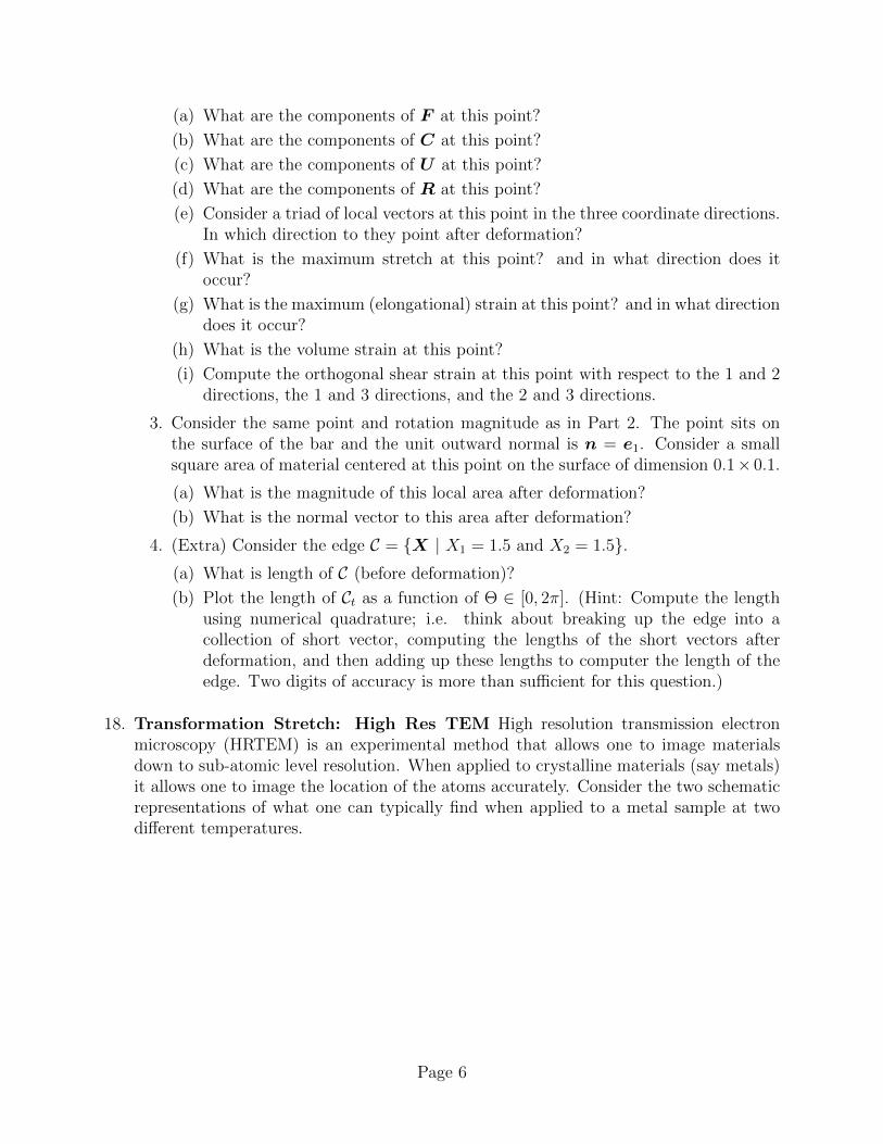
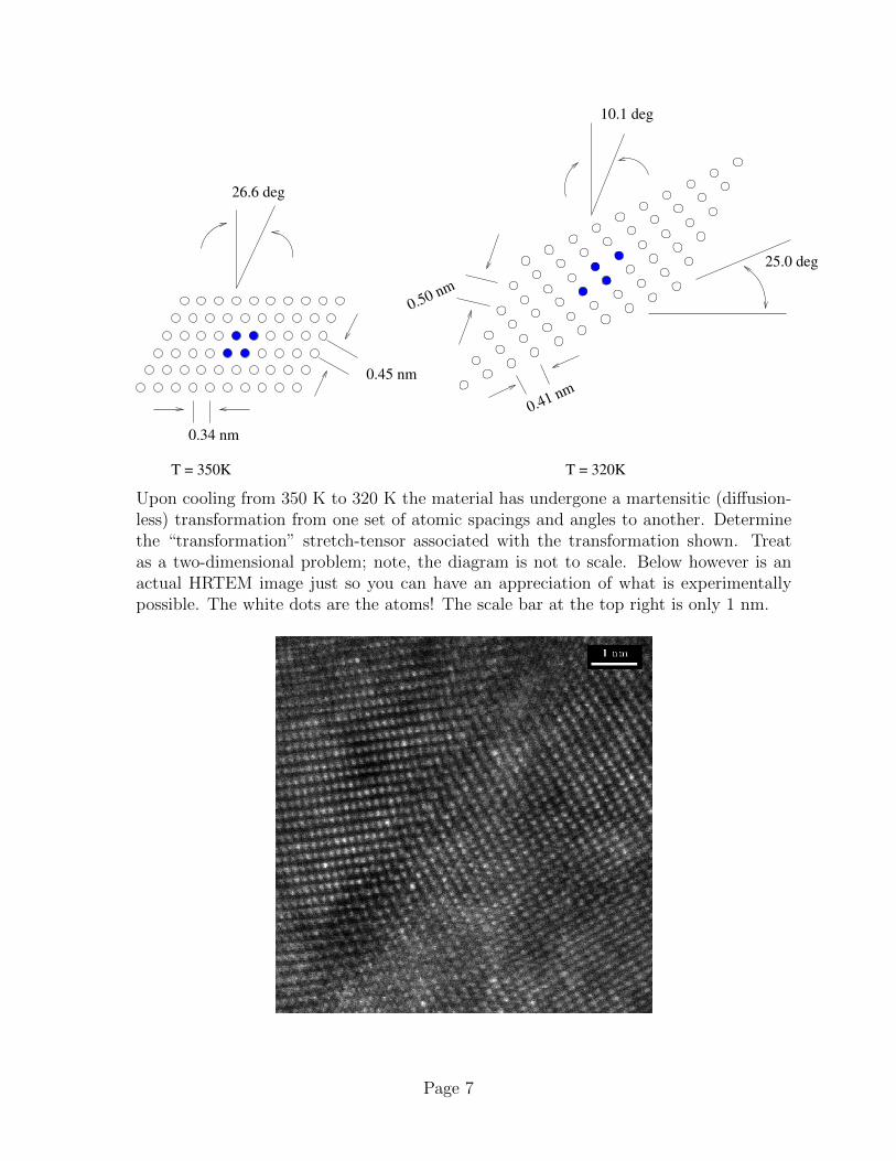
18. Transformation Stretch: High Res TEM High resolution transmission electronmicroscopy (HRTEM) is an experimental method that allows one to image materialsdown to sub-atomic level resolution. When applied to crystalline materials (say metals)it allows one to image the location of the atoms accurately. Consider the two schematicrepresentations of what one can typically find when applied to a metal sample at twodifferent temperatures.
Page 6
10.1 deg
0.34 nm
26.6 deg
0.45 nm
25.0 deg
T = 350K T = 320K
0.41 nm
0.50 nm
Upon cooling from 350 K to 320 K the material has undergone a martensitic (diffusion-less) transformation from one set of atomic spacings and angles to another. Determinethe “transformation” stretch-tensor associated with the transformation shown. Treatas a two-dimensional problem; note, the diagram is not to scale. Below however is anactual HRTEM image just so you can have an appreciation of what is experimentallypossible. The white dots are the atoms! The scale bar at the top right is only 1 nm.
Page 7
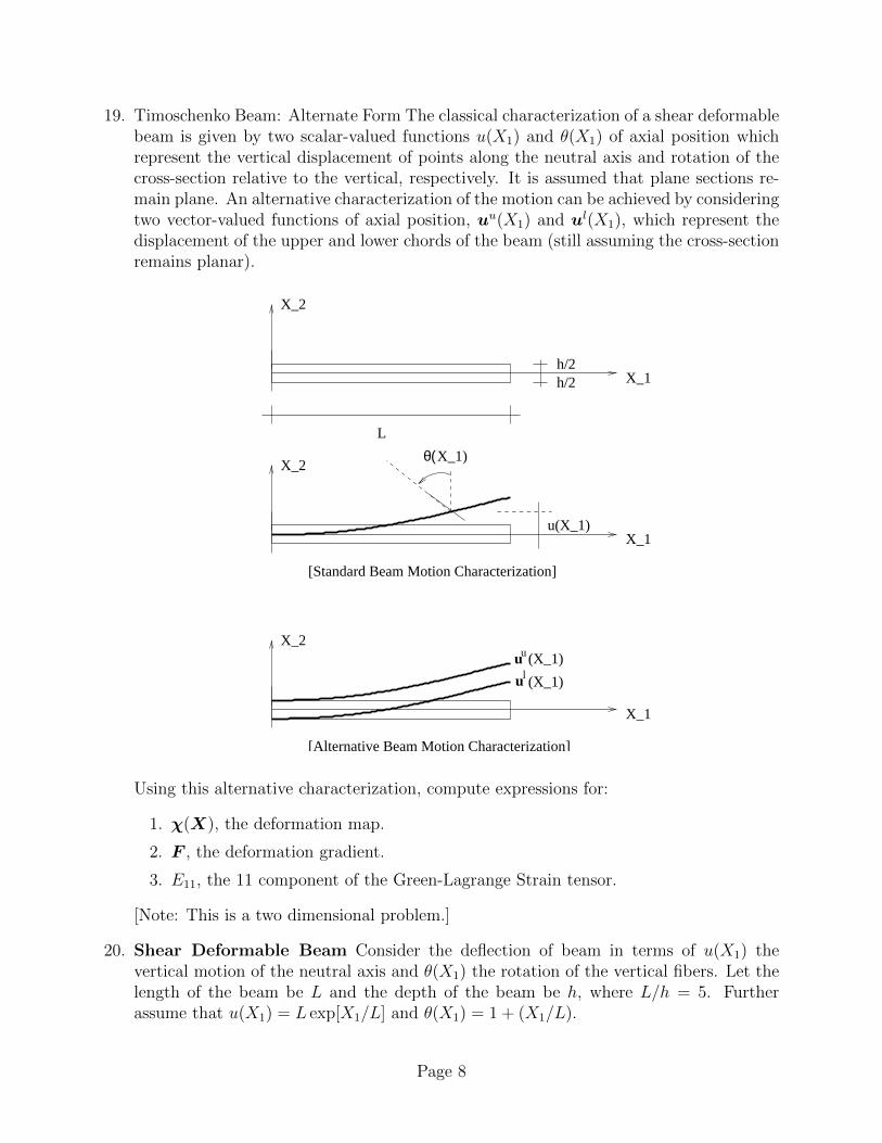
19. Timoschenko Beam: Alternate Form The classical characterization of a shear deformablebeam is given by two scalar-valued functions u(X1) and θ(X1) of axial position whichrepresent the vertical displacement of points along the neutral axis and rotation of thecross-section relative to the vertical, respectively. It is assumed that plane sections re-main plane. An alternative characterization of the motion can be achieved by consideringtwo vector-valued functions of axial position, uu(X1) and ul(X1), which represent thedisplacement of the upper and lower chords of the beam (still assuming the cross-sectionremains planar).
h/2h/2 X_1
X_2
X_1
X_2
u(X_1)
θ(X_1)
[Standard Beam Motion Characterization]
L
X_1
X_2
[Alternative Beam Motion Characterization]
u
l(X_1)
(X_1)
u
u
Using this alternative characterization, compute expressions for:
1. χ(X), the deformation map.
2. F , the deformation gradient.
3. E11, the 11 component of the Green-Lagrange Strain tensor.
[Note: This is a two dimensional problem.]
20. Shear Deformable Beam Consider the deflection of beam in terms of u(X1) thevertical motion of the neutral axis and θ(X1) the rotation of the vertical fibers. Let thelength of the beam be L and the depth of the beam be h, where L/h = 5. Furtherassume that u(X1) = L exp[X1/L] and θ(X1) = 1 + (X1/L).
Page 8
1. Compute and accurately plot the normal strain H along the top fiber of the beam;i.e. plot H((X1, h/2), e1).
2. Compute and accurately plot the orthogonal shear strain along the neutral axisbetween e1 and e2.
21. Beam Stretch Tensor and Rotation Consider a beam with reference configurationR = X | X1 ∈ [0, L] and X2 ∈ [−h
2, h
2] and a deformation:
x1 = X1 −X2 sin[θ(X1)]
x2 = X2 + u(X1)−X2(1− cos[θ(X1)]), .
Assume θ(X1) = X1/L and u(X1) = L2(X1/L)2. Determine the value of the right stretch
tensor field and rotation tensor field at the tip of the beam (X1, X2) = (L, 0). Computethe tensors numerically (not analytically). Use a calculator capable of eigencomputationsor, better, use MATLAB.
22. Area Change The motion of a body is given by:
x1 = 4X1 − 3(X2 − 2)
x2 = (X1)3
x3 = X3 .
Consider the square area whose 4 corners are the points (1, 1, 0), (1, 2, 0) ,(2, 2, 0), and(2, 1, 0) in the undeformed configuration of the body. After deformation the squarechanges shape to something that is no longer a square. Compute the area of this newshape. Note that the sides of the square becomes curves when the motion occurs! Hints:(1) This is a finite deformation problem. (2) Nanson’s formula nda = JF−TnRdA.
23. Area Strain Consider a thin square sheet which occupies a region [−L2, L
2]× [−L
2, L
2]×
[− t2, t
2], where t L. The sheet is deflected such that its deformation map is given by:
x1 = X1
x2 = X2
x3 = X3 + k
(X1 −
L
2
)2(X2 −
L
2
)2
,
where k is a given constant. Consider a small patch of material on the surface of thesheet near the point (L
4, L
4, t
2) and determine area strain at this point; i.e. determine
∆A/A at this point for the material on the outer surface of the body.
24. Screw Dislocation A screw dislocation in a solid is characterized by a displacementfield of the form
u3(X) =b
2πtan−1
(X1
X2
),
where b is the (given) magnitude of the Burger’s vector and the dislocation is assumedto align with the 3-axis; u1 = u2 = 0. Find the Green-Lagrange strain tensor associatedwith the dislocation.
Page 9
25. Torsional Volume Strain Consider a round rod of radius R and length L with referenceplacement R = X | (X1)2 + (X2)2 ≤ R2 and 0 ≤ X3 ≤ L. The rod undergoes atorsional motion:
x1 = X1 cos(θ(X3)) +X2 sin(θ(X3))
x2 = −X1 sin(θ(X3)) +X2 cos(θ(X3))
x3 = X3
where θ(X3) is a given but unspecified function. Compute the volumetric strain field.
26. Rigid Body Mechanics Consider a body B undergoing a time dependent rigid motionx(t) = R(t)X + c(t), where R(t) ∈ SO(3) and c(t) ∈ R3 are known.
1. Show that the velocity v = x can be written as v = ω × (x− c) + c, where ω is asuitably defined vector. Hint, RRT ∈ so(3); i.e. it is skew-symmetric.
2. Define the center of mass position of the body as
x =1
M
∫Btxρdv
and the center of mass velocity as
v =1
M
∫Btvρdv .
Show the center of mass velocity can be written as v = ω× (x− c) + c. It directlyfollows, then that the linear momentum of the body l =
∫Bt ρvdv can be written as
l = M v, where M =∫Bt ρdv is the mass of the body.
3. The angular momentum of the body is defined to be h =∫Bt x× ρvdv. Show that
this can be written ash = x× l + Jω ,
where the second order inertia tensor J =∫Bt ρ[(x−x)·(x−x)1−(x−x)⊗(x−x)]dv.
Hint, it the last step it is useful to note that a × b × c = [(a · c)1 − c ⊗ a]b. Touse this hint, however, you must first prove it.
27. Speckle Field Interferometry Speckle pattern interferometry is an experimentalmethodology which provides near full field two dimensional deformation mapping infor-mation for the surface of a body. The accompanying file provides data in the followingformat: in each row one finds in columns 1 and 2 the X1 and X2(in-plane) referencecoordinates of a material point and in columns 3 and 4 the corresponding displacementcomponents u1 and u2 of the same material point. The data is representative of a 50 by50 grid of data points in the center of the measurement field. Estimate
1. the magnitude,
Page 10
2. material direction and
3. material location of the maximum stretch and
4. the magnitude and
5. material location of the maximum volumetric strain.
Assume that there is no displacement in the out-of-plane direction.
28. Incompressible Measures Let ϕ : Ω → R3 be a given motion and let F = ∂ϕ/∂Xbe the deformation gradient. Define
F = J−13F
where J = det[F ].
(a) Justify the name volume preserving part of F often assigned to F . Give a physicalinterpretation.
(b) Define:
l = ( ˙F F−1
) ; d =1
2(l + l
T) (2)
Find the relation between l and l = ∂v/∂x, where v(x) is the spatial velocity field. Findthe relation between d and d. Compute tr[d] and tr[l]. Give a physical interpretation.[Remark: These relations play a crucial role in the mechanics of incompressible materialsand large deformation plasticity.]
29. Function Linearization Consider the vector valued function v(H) = H ·H · a+ (1 :H)a, where H is a second order tensor and a is a given constant vector. Linearize thefunction v(H) about Ho = 1; i.e. find a linear approximation to v(H) for values of Hnear 1.
30. Function Linearization Consider the function f(H) = cos (H : H) where H is thegradient of the displacement field. Find the linearization of f near H = 0.
31. Linearization Mooney-Rivlin Energy Linearize the function f(H) = k1(I1 − 3) +k2(I2 − 3) about H = 0, where k1 and k2 are given constants and I1 and I2 are, respec-tively, the first and second invariants of H .
32. Linearization of Rotation For everyR ∈ SO(3) there exists three orthonormal vectorsp, q, r and a scalar θ ∈ R such that
R = p⊗ p+ cos(θ)[q ⊗ q + r ⊗ r]− sin(θ)[q ⊗ r − r ⊗ q] .
Linearize this expression for small angles of rotation θ and show that such rotations canbe approximated by the identity plus a skew-symmetric tensor.
33. Spin Tensor Consider a time dependent tensor Q(t) ∈ SO(3) – i.e. a rotation tensor.Show that
Page 11
1. the tensor Ω(t) = Q ·QT is skew-symmetric (i.e. Ω ∈ so(3)) and
2. if a(t) = Q(t) ·A, then a(t) = Ω · a, where A is a given constant vector.
34. Linearized Jacobian Consider a displacement field is u = [20X2Y e1 +10(Y 2 +Z2)e2 +(X+3Z3)e3]×10−2. Find the deformation gradient, the Jacobian, and small deformationvolume strain. Assess the the approximation Lin[J ] = 1 + ui,i at the point (1, 2,−3).[(X, Y, Z) = (X1, X2, X3)]
35. Analysis of Motion Consider the deformation map x1 = X1, x2 = X2 + kX21 , x3 = X3
for a tri-unit cube R = [0, 1]× [0, 1]× [0, 1], where k is a scalar parameter.
1. Compute the normal strain at (12, 1
2, 1
2) in the direction oriented along the vector
(1, 2, 3). [Warning! Normalize!]
2. Compute the orthogonal shear at this point between the two direction (1/√
2, 1/√
2, 0)and (−1/
√2, 1/√
2, 0).
3. For parts 1 and 2, determine the value below which k has to be for the small strainapproximations to have a relative error of less than 10−4. For the case of orthogonalshear, also examine the absolute error.
36. Deformation of a bar: Consider a square bar Ω = [−a2, a
2] × [−a
2, a
2] × [0, L] – side
length a and longitudinal length L. The bar is deformed according to
ϕ(X) = (X1 + βX2 + αX3) e1 + (X2 − βX1 + αX3) e2 +(X3 + αX2
3
)e3 , (45)
where α and β are given constants.
1. Determine the deformation gradient; assume arbitrary α and β.
2. Determine the Green-Lagrange strain tensor; assume arbitrary α and β.
3. Under the assumption that |α| 1 and that |β| 1:
(a) Determine the small strain tensor.
(b) Assuming a linear elastic isotropic material, determine the Cauchy stress tensor.
(c) Determine the total force and moment/torque that must have been applied onthe end of the bar, X3 = L.
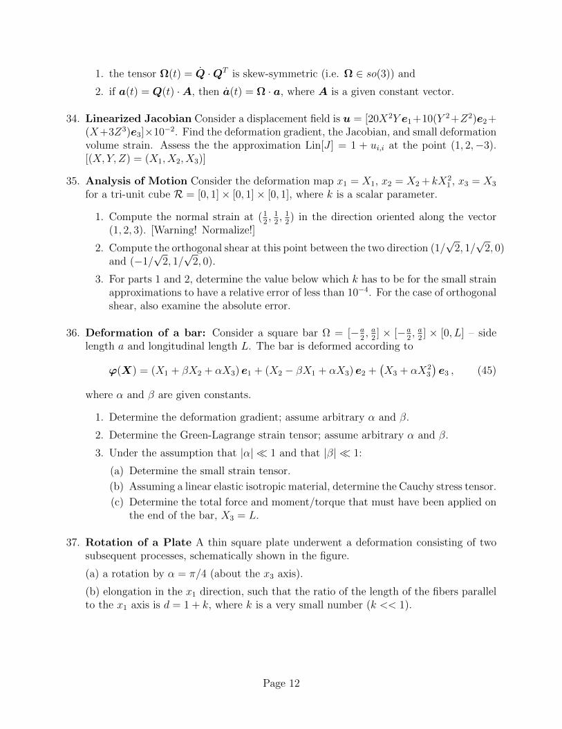
37. Rotation of a Plate A thin square plate underwent a deformation consisting of twosubsequent processes, schematically shown in the figure.
(a) a rotation by α = π/4 (about the x3 axis).
(b) elongation in the x1 direction, such that the ratio of the length of the fibers parallelto the x1 axis is d = 1 + k, where k is a very small number (k << 1).
Page 12
A
B
A
Bd d
B
A
α
d d(1+k)
(Original) (Intermediate) (Final)(a) (b)
X1, x1 X1, x1 X1, x1
X2, x2 X2, x2 X2, x2
Calculate the following field quantities:
(i) total displacement (from the original state to the final state) as a function of X1 andX2.
(ii) components of the Green-Lagrange strain tensor E and its linear part ε. Is ε a goodapproximation to E? Comment on it.
38. Validity of Small Strain Tensor Consider a cube, in its undeformed configuration,that occupies the region Ω = [0, 1]× [0, 2]× [0, 2]. The cube is subject to a set of loadsthat results in a deformation map
χ(X) = δ(X1 +X2)e1 + δ(X23 )e2 + δ(X1X
22 )e3 .
How small must δ be for the linear strain tensor, ε, to be a valid approximation to theGreen-Lagrange strain tensor, E. Valid is defined for the purposes of this problem as
maxX∈Ω
‖ε(X)−E(X)‖ < 10−3
Note that an appropriate definition for the norm of a tensor is ‖T ‖ =√T : T =
√TijTij.
A small computer program is perhaps the best way to solve this problem.
39. Rigid Motion Consider a rigid rotation x = R(X − 0) + c, where R ∈ SO(2) isconstant and c ∈ R2 is also constant. Noting that in component form we can express
RiA =
[cos(β) sin(β)− sin(β) cos(β)
], (46)
find E and compare it to ε. Comment on the validity of ε.
40. Rigid Motion Consider a rigid rotation x = Q · (X − 0) + c, where Q ∈ SO(3) is aconstant tensor and c ∈ R3 is a constant vector. Noting that in component form we canin general write, for some coordinate frame,
QiA =
cos(α) − sin(α) 0sin(α) cos(α) 0
0 0 1
,
where α ∈ R is the rotation angle.
Page 13
1. Compute E and compare it to ε.
2. Compute the rotation in the polar decomposition (F = RU )and compare it to1 + ω.
Comment on the validity of ε and ω.
41. Classical Derivation of Shear Formula Derive γ12 via the classical construction ofangle changes associated with neighboring points in the small strain setting.
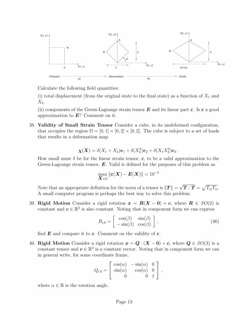
42. Incompressibility An incompressible material is one where the volumetric strains mustbe equal to zero at all points. Consider an incompressible body Ω which is deformedby imposing displacements at all points on the boundary ∂Ω. What condition must theimposed boundary displacements satisfy in order to be compatible with the incompress-ibility constraint? [Assume small displacement theory.]
Ω
X_2X_1
X_3
Ω
Imposed displacements on all points of
43. Small Deformation Timoshenko Beam Consider a Timoshenko beam initially occu-pying the region [0, L]× [−h/2, h/2]. The beam is deformed into a sinusoidal shape suchthat u(X1) = A sin(kX1) and θ(X1) = 0, where k and A are given constants. Assumesmall strains and compute the (orthogonal) shear strain with respect to e1 and e2 in thebeam as a function of position.
44. Small strain field analysis Consider a (small) strain field ε(x) whose compents aregiven by
εij =
3x 5y + 6z z3
5y + 6z 0 x2 + y2
z3 x2 + y2 exp(x)
× 10−6 . (54)
1. Find the principal strains and directions at xi = (1, 2, 3).
2. What is the normal strain in the direction ni = (1, 1, 1) at the point xi = (2, 2, 0)?
3. What is the change in angle between v(1)i = (1, 1, 1) and v
(2)i = (2, 1, 3) at the point
xi = (1, 1, 1)?
4. What is the volumetric strain at xi = (0, 0, 0)?
Page 14
Hint: don’t waste your time doing these by hand! Use MATLAB or some-thing similar.
45. Small Strain Field Analysis Consider a (small) strain field ε(x) whose componentsare given by
εij =
3x2x2 x2 + x3 (x3)3
x2 + x3 x1 x1 + x3
(x3)3 x1 + x3 cos(x1)
× 10−6 . (55)
1. Find the principal strains and directions at xi = (2, 0, 1).
2. What is the normal strain in the direction ni = (1, 1, 1) at the point xi = (2, 2, 0)?[Careful: remember to normalize.]
3. What is the change in angle between v(1)i = (2, 1, 1) and v
(2)i = (2, 1, 2) at the point
xi = (0, 1, 1)?
4. What is the volumetric strain at xi = (1, 0, 0)?
Hint: Don’t waste your time doing these by hand! Use MATLAB or some-thing similar.
46. Small Strain Field Analysis The strain at a particular point in a body is given by
ε ∼
7 8 08 9 30 3 55
× 10−5
in the a, b, c basis where a = 1√3(e1 + e2 + e3), b = 1√
2(e1 − e2), and c = 1√
6(e1 +
e2 − 2e3).
1. Find the max normal and shear strains at this point.
2. Find the normal strain in the e1 direction at this point.
3. Find the angle change between the e1 and e2 directions at this point.
47. Small Strain Field Analysis Let a = 1e1 + 1e2 + 1e3, b = 2e1 + 1e2 + 1e3. Thehomogeneous strain in a body is given as ε = (a · b)(a⊗ b+ b⊗ a).
1. What is the minimum normal strain (in absolute value) and in which direction doesit occur?
2. Find any two vectors such that the angle between them does not change under thedeformation.
3. Now consider imposing an additional homogenous strain ε on the body. Whatproperty must ε have in order for the overall motion to be volume preserving?
Page 15
48. Wave Motion Consider the following motion
x = X + b cos(k ·X − ct) t ≥ 0
where b is a known constant vector such that ‖b‖ << 1, k is a known constant vector,c > 0 is a known constant scalar, and t is time.
1. Determine the strain field associated with this motion.
2. Find the directions in which the normal strains must be zero for all times and atall points.
3. Find a condition between k and b such that the motion is isochoric at all pointsfor all times.
4. Describe the motion physically.
49. Spectral Representation and Transformation You are told that the principalstrains at a point are (9.6235, 0.0000, −0.6235, ) × 10−6 and that the correspondingeigenvectors in the ei basis are
n(1) →
0.38510.55950.7339
, n(2) →
0.4082−0.8165
0.4082
, n(3) →
0.82770.1424−0.5428
.
1. What are the components of the strain tensor in the ei basis? Express youranswer to only 2 significant digits.
2. Suppose one changes basis such that
a1 = 1√3e1 + 1√
3e2 + 1√
3e3, ,
a2 = 0e1 + 1√2e2 − 1√
2e3, ,
a3 = − 2√6e1 + 1√
6e2 + 1√
6e3 ,
where ai represent new basis vectors. What are the components of of the straintensor in the ai basis?
50. Spectral Representation and Transformation You are told that the principalstrains at a point are (0.0000, 0.9875, 81.0125)×10−6 and that the corresponding eigen-vectors in the ei basis are
n(1) →
0.00000.8944−0.4472
, n(2) →
0.9937−0.0503−0.1006
, n(3) →
0.11250.44440.8888
.
1. What are the components of the strain tensor in the ei basis? Express youranswer to only 2 significant digits.
Page 16
2. Suppose one changes basis such that
a1 = 1√3e1 + 1√
3e2 + 1√
3e3, ,
a2 = 0e1 + 1√2e2 − 1√
2e3, ,
a3 = − 2√6e1 + 1√
6e2 + 1√
6e3 ,
where ai represent new basis vectors. What are the components of the strain tensorin the ai basis?
51. Spectral Representation and Transformation You are told that the principalstrains at a point are (−6.4752, 0.2270, 12.2483) × 10−6 and that the correspondingeigenvectors in the ei basis are
n(1) →
−0.65530.38740.6485
, n(2) →
0.1319−0.7866
0.6032
, n(3) →
0.74380.48080.4643
.
1. What are the components of the strain tensor in the ei basis? Express youranswer to only 2 significant digits.
2. Suppose one changes basis such that
a1 =√
32e1 + 1
4e2 +
√3
4e3, ,
a2 = −12e1 +
√3
4e2 + 3
4e3, ,
a3 = 0e1 −√
32e2 + 1
2e3 ,
where ai represent new basis vectors. What are the components of the strain tensorin the ai basis?
3. Verify that the three invariants of the strain tensor are the same in both bases.
52. Extremal Normal Strains You are told that the (small) strain tensor at a particularpoint in a body is given by
ε = [e1 ⊗ e1 + 2(e1 ⊗ e2 + e2 ⊗ e1)− 6(e1 ⊗ e3 + e3 ⊗ e1)
3e2 ⊗ e2 + 2(e2 ⊗ e3 + e3 ⊗ e2)− 3e3 ⊗ e3]× 10−4 .
Determine the algebraically maximum and minimum normals strains at this point andtheir corresponding directions.
53. Volume Average Strains Define the volume average strain in a body by
ε =1
V
∫Ω
ε dΩ
where V is the volume of the body Ω. Show that
ε =1
2V
∫∂Ω
u⊗ n+ n⊗ u dΓ
Page 17
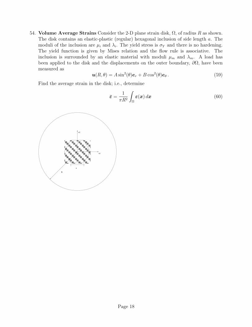
54. Volume Average Strains Consider the 2-D plane strain disk, Ω, of radius R as shown.The disk contains an elastic-plastic (regular) hexagonal inclusion of side length a. Themoduli of the inclusion are µi and λi. The yield stress is σY and there is no hardening.The yield function is given by Mises relation and the flow rule is associative. Theinclusion is surrounded by an elastic material with moduli µm and λm. A load hasbeen applied to the disk and the displacements on the outer boundary, ∂Ω, have beenmeasured as
u(R, θ) = A sin2(θ)er +B cos2(θ)eθ . (59)
Find the average strain in the disk; i.e., determine
ε =1
πR2
∫Ω
ε(x) dx (60)
R
x1
x2
a
Page 18