Quantumized Microwave Detection Based on -Type Three-level ...
12
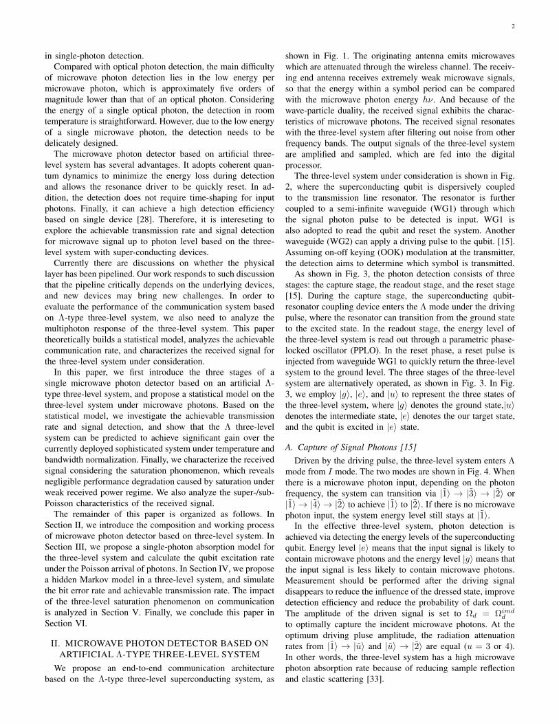
1 Quantumized Microwave Detection Based on Λ-Type Three-level Superconducting System: HMM Modeling and Performance Prediction Junyu Zhang, Chen Gong, Shangbin Li, Shanchi Wu, Rui Ni, Chengjie Zuo, Jinkang Zhu, Ming Zhao, and Zhengyuan Xu Abstract—We adopt artificial Λ-type three-level system with superconducting devices for microwave signal detection, where the signal intensity reaches the level of discrete photons instead of continuous waveform. Based on the state transition principles of the three-level system, we propose a statistical model for microwave signal detection. In addition, achievable transmission rates and signal detection based on the proposed statistical models are investigated for low temperature conditions in deep space communication scenario. It is predicted that high sensitivity can be achieved by the proposed system. We further characterize the received signal considering the saturation phonomenon of three- level system, which reveals negligible performance degradation caused by saturation under weak received power regime. Key Words: Microwave photon detection, Λ-type Three-level system, Superconducting devices, Energy-level transition. I. INTRODUCTION With the development of wireless communication systems, the signal reception and detection under weak power regime has attracted extensive attention from both academia and industrial areas. One application lies in satellite communica- tion under long transmission distance [1]–[5]. In particular, extremely high channel attenuation due to long transmission distance requires large transmission power, large antenna size and high-sensitivity receiver. Among the three factors, high- sensitivity receiver can lead to reduced transmission power requirements and antenna size, which becomes the most fundamental one in improving the communication perfor- mance. Based on the principle of wave-particle duality, under extremely weak electromagnetic field intensity, microwave signal may degenerate from continuous waveforms to discrete photons. Such fact inspires us to adopt microwave photon level detection. On the other hand, from perspectives of condensed mat- ter physics and quantum physics, Josephson junction [6]– [10] or nitrogen-vacancy center [11], [12] is adopted for This work was supported by National Key Research and Development Program of China (Grant No. 2018YFB1801904), Key Program of National Natural Science Foundation of China (Grant No. 61631018), Key Research Program of Frontier Sciences of CAS (Grant No. QYZDY-SSW-JSC003). Junyu Zhang, Chen Gong, Shangbin Li, Shanchi Wu, Chengjie Zuo, Jinkang Zhu, Ming Zhao, and Zhengyuan Xu are with Key Laboratory of Wireless- Optical Communications, Chinese Academy of Sciences, School of Informa- tion Science and Technology, University of Science and Technology of China, Hefei, China. Email: [email protected], {cgong821,shbli, wsc, czuo, jkzhu, zhaoming, xuzy}@ustc.edu.cn. Rui Ni is with Huawei Technology, Shenzhen, China. Email: [email protected]. microwave photon sensing. Compared with nitrogen-vacancy center, Josephson junction using super-conducting devices has higher sensitivity for the signals with carrier up to Giga Hertz. Moreover, super-conducting devices can significantly reduce the resistance compared with the currently adopted semi-conducting devices, and thus can significantly increase the detection sensitivity. The superconducting circuit is also a good choice to implement the quantum computer bus and quantum nodes [13], [14]. In deep space communication, the thermal noise of space receiver rather than interference becomes a crucial factor on the communication performance. Low thermal noise can be realized due to low temperature in the deep space scenario, which can be down to several Kelvins. Another way to achieve single photon detection is based on the strong coupling between a single quantum emitter and a one-dimensional photon field [15]. Due to the energy dissipation interference between the incident field and the radiation of the emitter, the interaction between the emitter and the photon is greatly enhanced. This opens up the possibility of determining the control of the quantum system by a single photon and the possibility of single-photon level detection. In the field of optics, there have been extensive theoretical and experimental works in the quantum physic area [16]–[24]. In the microwave field, coupling system of two-level systems and quantum harmonic oscillators can interact with microwave photons based on cavity QED (Quantum Electrodynamics) or circuit QED, and can be used for single microwave photon detection and quantum states synthesis [25]–[27]. In particu- lar, a single microwave photon can almost certainly induce a transition in a Λ-type three-level system composed of a resonator and a superconducting qubit dispersion coupling, and change the energy level of the system [28]. In this case, the driving signal induces the coupling system to produce the Rabi oscillation to design the dressed state. The intensity of the driving signal determines the coupling degree between the resonator level and the superconducting qubit level in the dressed state. Appropriate driving signal intensity makes the four main decay paths of the coupled system have the identical decay rate. We call the three-level system working in Λ mode [29], [30]. In case of impedance matching, the reflected field amplitude of the continuous microwave signal incident on the three-level system is almost zero. In other words, almost each input microwave photon can cause the energy level transition of the three-level system [31]–[33], which implies that the three-level system has high efficiency arXiv:2006.14497v3 [eess.SP] 27 Aug 2021
Transcript of Quantumized Microwave Detection Based on -Type Three-level ...
1
Quantumized Microwave Detection Based onΛ-Type Three-level Superconducting System: HMM
Modeling and Performance PredictionJunyu Zhang, Chen Gong, Shangbin Li, Shanchi Wu, Rui Ni, Chengjie Zuo, Jinkang Zhu, Ming Zhao, and
Zhengyuan Xu
Abstract—We adopt artificial Λ-type three-level system withsuperconducting devices for microwave signal detection, wherethe signal intensity reaches the level of discrete photons insteadof continuous waveform. Based on the state transition principlesof the three-level system, we propose a statistical model formicrowave signal detection. In addition, achievable transmissionrates and signal detection based on the proposed statistical modelsare investigated for low temperature conditions in deep spacecommunication scenario. It is predicted that high sensitivity canbe achieved by the proposed system. We further characterize thereceived signal considering the saturation phonomenon of three-level system, which reveals negligible performance degradationcaused by saturation under weak received power regime.
Key Words: Microwave photon detection, Λ-type Three-levelsystem, Superconducting devices, Energy-level transition.
I. INTRODUCTION
With the development of wireless communication systems,the signal reception and detection under weak power regimehas attracted extensive attention from both academia andindustrial areas. One application lies in satellite communica-tion under long transmission distance [1]–[5]. In particular,extremely high channel attenuation due to long transmissiondistance requires large transmission power, large antenna sizeand high-sensitivity receiver. Among the three factors, high-sensitivity receiver can lead to reduced transmission powerrequirements and antenna size, which becomes the mostfundamental one in improving the communication perfor-mance. Based on the principle of wave-particle duality, underextremely weak electromagnetic field intensity, microwavesignal may degenerate from continuous waveforms to discretephotons. Such fact inspires us to adopt microwave photon leveldetection.
On the other hand, from perspectives of condensed mat-ter physics and quantum physics, Josephson junction [6]–[10] or nitrogen-vacancy center [11], [12] is adopted for
This work was supported by National Key Research and DevelopmentProgram of China (Grant No. 2018YFB1801904), Key Program of NationalNatural Science Foundation of China (Grant No. 61631018), Key ResearchProgram of Frontier Sciences of CAS (Grant No. QYZDY-SSW-JSC003).Junyu Zhang, Chen Gong, Shangbin Li, Shanchi Wu, Chengjie Zuo, JinkangZhu, Ming Zhao, and Zhengyuan Xu are with Key Laboratory of Wireless-Optical Communications, Chinese Academy of Sciences, School of Informa-tion Science and Technology, University of Science and Technology of China,Hefei, China. Email: [email protected], cgong821,shbli, wsc, czuo,jkzhu, zhaoming, [email protected].
Rui Ni is with Huawei Technology, Shenzhen, China. Email:[email protected].
microwave photon sensing. Compared with nitrogen-vacancycenter, Josephson junction using super-conducting devices hashigher sensitivity for the signals with carrier up to GigaHertz. Moreover, super-conducting devices can significantlyreduce the resistance compared with the currently adoptedsemi-conducting devices, and thus can significantly increasethe detection sensitivity. The superconducting circuit is alsoa good choice to implement the quantum computer bus andquantum nodes [13], [14]. In deep space communication,the thermal noise of space receiver rather than interferencebecomes a crucial factor on the communication performance.Low thermal noise can be realized due to low temperature inthe deep space scenario, which can be down to several Kelvins.
Another way to achieve single photon detection is basedon the strong coupling between a single quantum emitterand a one-dimensional photon field [15]. Due to the energydissipation interference between the incident field and theradiation of the emitter, the interaction between the emitter andthe photon is greatly enhanced. This opens up the possibilityof determining the control of the quantum system by a singlephoton and the possibility of single-photon level detection.In the field of optics, there have been extensive theoreticaland experimental works in the quantum physic area [16]–[24].In the microwave field, coupling system of two-level systemsand quantum harmonic oscillators can interact with microwavephotons based on cavity QED (Quantum Electrodynamics) orcircuit QED, and can be used for single microwave photondetection and quantum states synthesis [25]–[27]. In particu-lar, a single microwave photon can almost certainly inducea transition in a Λ-type three-level system composed of aresonator and a superconducting qubit dispersion coupling,and change the energy level of the system [28]. In this case,the driving signal induces the coupling system to produce theRabi oscillation to design the dressed state. The intensity ofthe driving signal determines the coupling degree betweenthe resonator level and the superconducting qubit level inthe dressed state. Appropriate driving signal intensity makesthe four main decay paths of the coupled system have theidentical decay rate. We call the three-level system workingin Λ mode [29], [30]. In case of impedance matching, thereflected field amplitude of the continuous microwave signalincident on the three-level system is almost zero. In otherwords, almost each input microwave photon can cause theenergy level transition of the three-level system [31]–[33],which implies that the three-level system has high efficiency
arX
iv:2
006.
1449
7v3
[ee
ss.S
P] 2
7 A
ug 2
021
2
in single-photon detection.Compared with optical photon detection, the main difficulty
of microwave photon detection lies in the low energy permicrowave photon, which is approximately five orders ofmagnitude lower than that of an optical photon. Consideringthe energy of a single optical photon, the detection in roomtemperature is straightforward. However, due to the low energyof a single microwave photon, the detection needs to bedelicately designed.
The microwave photon detector based on artificial three-level system has several advantages. It adopts coherent quan-tum dynamics to minimize the energy loss during detectionand allows the resonance driver to be quickly reset. In ad-dition, the detection does not require time-shaping for inputphotons. Finally, it can achieve a high detection efficiencybased on single device [28]. Therefore, it is intereseting toexplore the achievable transmission rate and signal detectionfor microwave signal up to photon level based on the three-level system with super-conducting devices.
Currently there are discussions on whether the physicallayer has been pipelined. Our work responds to such discussionthat the pipeline critically depends on the underlying devices,and new devices may bring new challenges. In order toevaluate the performance of the communication system basedon Λ-type three-level system, we also need to analyze themultiphoton response of the three-level system. This papertheoretically builds a statistical model, analyzes the achievablecommunication rate, and characterizes the received signal forthe three-level system under consideration.
In this paper, we first introduce the three stages of asingle microwave photon detector based on an artificial Λ-type three-level system, and propose a statistical model on thethree-level system under microwave photons. Based on thestatistical model, we investigate the achievable transmissionrate and signal detection, and show that the Λ three-levelsystem can be predicted to achieve significant gain over thecurrently deployed sophisticated system under temperature andbandwidth normalization. Finally, we characterize the receivedsignal considering the saturation phonomenon, which revealsnegligible performance degradation caused by saturation underweak received power regime. We also analyze the super-/sub-Poisson characteristics of the received signal.
The remainder of this paper is organized as follows. InSection II, we introduce the composition and working processof microwave photon detector based on three-level system. InSection III, we propose a single-photon absorption model forthe three-level system and calculate the qubit excitation rateunder the Poisson arrival of photons. In Section IV, we proposea hidden Markov model in a three-level system, and simulatethe bit error rate and achievable transmission rate. The impactof the three-level saturation phenomenon on communicationis analyzed in Section V. Finally, we conclude this paper inSection VI.
II. MICROWAVE PHOTON DETECTOR BASED ONARTIFICIAL Λ-TYPE THREE-LEVEL SYSTEM
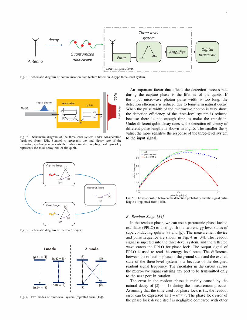
We propose an end-to-end communication architecturebased on the Λ-type three-level superconducting system, as
shown in Fig. 1. The originating antenna emits microwaveswhich are attenuated through the wireless channel. The receiv-ing end antenna receives extremely weak microwave signals,so that the energy within a symbol period can be comparedwith the microwave photon energy hν. And because of thewave-particle duality, the received signal exhibits the charac-teristics of microwave photons. The received signal resonateswith the three-level system after filtering out noise from otherfrequency bands. The output signals of the three-level systemare amplified and sampled, which are fed into the digitalprocessor.
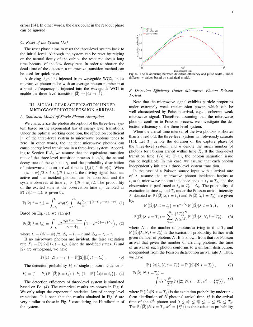
The three-level system under consideration is shown in Fig.2, where the superconducting qubit is dispersively coupledto the transmission line resonator. The resonator is furthercoupled to a semi-infinite waveguide (WG1) through whichthe signal photon pulse to be detected is input. WG1 isalso adopted to read the qubit and reset the system. Anotherwaveguide (WG2) can apply a driving pulse to the qubit. [15].Assuming on-off keying (OOK) modulation at the transmitter,the detection aims to determine which symbol is transmitted.
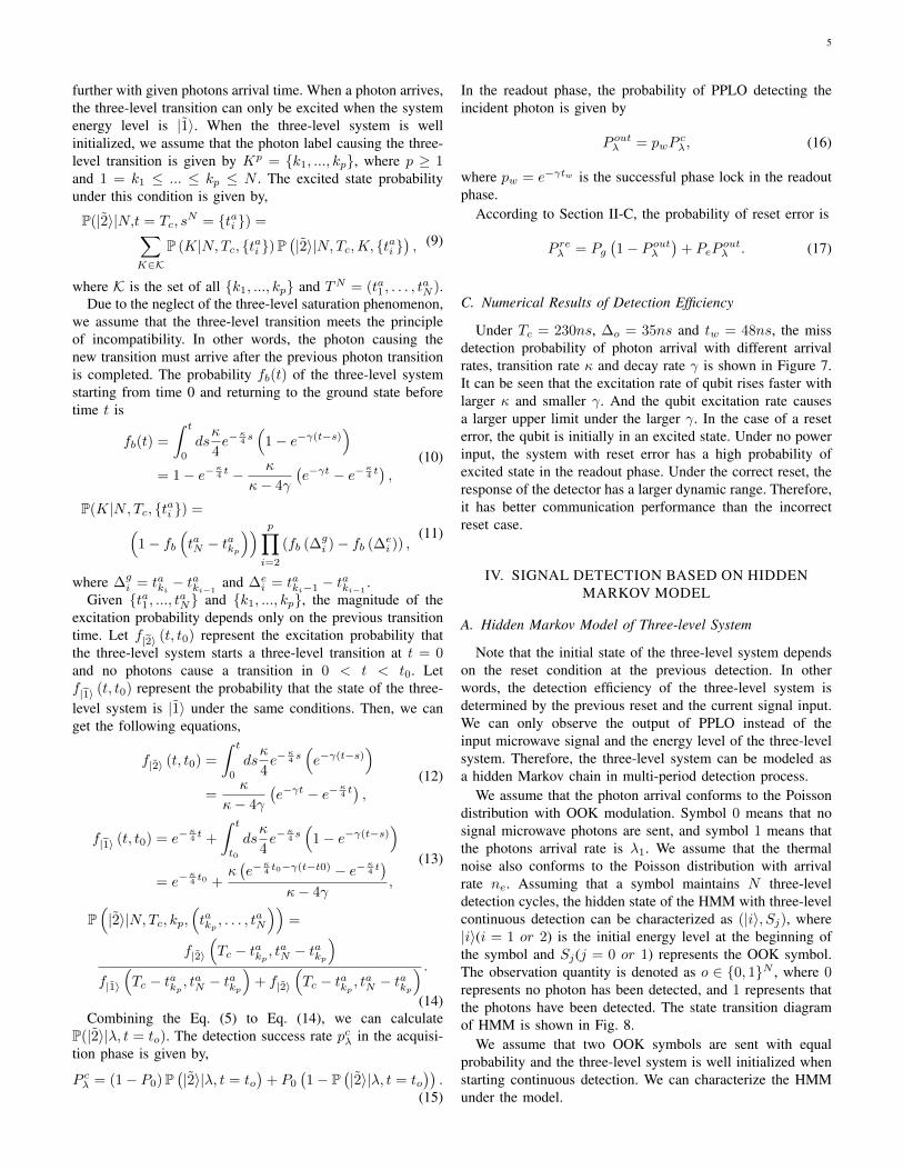
As shown in Fig. 3, the photon detection consists of threestages: the capture stage, the readout stage, and the reset stage[15]. During the capture stage, the superconducting qubit-resonator coupling device enters the Λ mode under the drivingpulse, where the resonator can transition from the ground stateto the excited state. In the readout stage, the energy level ofthe three-level system is read out through a parametric phase-locked oscillator (PPLO). In the reset phase, a reset pulse isinjected from waveguide WG1 to quickly return the three-levelsystem to the ground level. The three stages of the three-levelsystem are alternatively operated, as shown in Fig. 3. In Fig.3, we employ |g〉, |e〉, and |u〉 to represent the three states ofthe three-level system, where |g〉 denotes the ground state,|u〉denotes the intermediate state, |e〉 denotes the our target state,and the qubit is excited in |e〉 state.
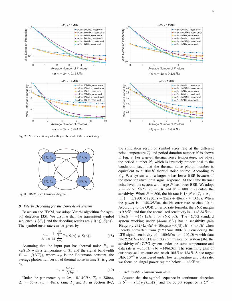
A. Capture of Signal Photons [15]Driven by the driving pulse, the three-level system enters Λ
mode from I mode. The two modes are shown in Fig. 4. Whenthere is a microwave photon input, depending on the photonfrequency, the system can transition via |1〉 → |3〉 → |2〉 or|1〉 → |4〉 → |2〉 to achieve |1〉 to |2〉. If there is no microwavephoton input, the system energy level still stays at |1〉.
In the effective three-level system, photon detection isachieved via detecting the energy levels of the superconductingqubit. Energy level |e〉 means that the input signal is likely tocontain microwave photons and the energy level |g〉 means thatthe input signal is less likely to contain microwave photons.Measurement should be performed after the driving signaldisappears to reduce the influence of the dressed state, improvedetection efficiency and reduce the probability of dark count.The amplitude of the driven signal is set to Ωd = Ωimdd
to optimally capture the incident microwave photons. At theoptimum driving pluse amplitude, the radiation attenuationrates from |1〉 → |u〉 and |u〉 → |2〉 are equal (u = 3 or 4).In other words, the three-level system has a high microwavephoton absorption rate because of reducing sample reflectionand elastic scattering [33].
3
Quantumized
microwave
Amplifier
Filter
Digital
processor
Three-level
system
Low temperature
Antenna
decay
Fig. 1. Schematic diagram of communication architecture based on Λ-type three-level system.
| 0
| 1
| 2| e
| !
"
# $
Fig. 2. Schematic diagram of the three-level system under consideration(replotted from [15]). Symbol κ represents the total decay rate of theresonator; symbol g represents the qubit-resonator coupling; and symbol γrepresents the total decay rate of the qubit.
|
|e
Readout Stage
|
|
|e
Capture Stage
Reset Stage |
|
|e
Fig. 3. Schematic diagram of the three stages.
| , = |
| , = |
| , = |
| , = |
|
|
|
|
mode mode
Fig. 4. Two modes of three-level system (replotted from [15]).
An important factor that affects the detection success rateduring the capture phase is the lifetime of the qubits. Ifthe input microwave photon pulse width is too long, thedetection efficiency is reduced due to long-term natural decay.When the pulse width of the microwave photon is very short,the detection efficiency of the three-level system is reducedbecause there is not enough time to make the transition.Under different qubit decay rates γ, the detection efficiency ofdifferent pulse lengths is shown in Fig. 5. The smaller the γvalue, the more sensitive the response of the three-level systemto the input signal.
10 100 1000
pulse length (ns)
0.5
0.6
0.7
0.8
0.9
1
dete
ction p
rob.
=0
=2 0.02MHz
=2 0.1MHz
Fig. 5. The relationship between the detection probability and the signal pulselength l (replotted from [15]).
B. Readout Stage [34]
In the readout phase, we can use a parametric phase-lockedoscillator (PPLO) to distinguish the two energy level states ofsuperconducting qubits |e〉 and |g〉. The measurement deviceand pulse sequence are shown in Fig. 4 in [34]. The readoutsignal is injected into the three-level system, and the reflectedwave enters the PPLO for phase lock. The output signal ofPPLO is used to read the energy level state. The differencebetween the reflection phase of the ground state and the excitedstate of the three-level system is π because of the designedreadout signal frequency. The circulator in the circuit causesthe microwave signal entering any port to be transmitted onlyto the next port in rotation.
The error in the readout phase is mainly caused by thenatural decay of |2〉 → |1〉 during the measurement process.Assuming that the time used for phase lock is tw, the readouterror can be expressed as 1− e−γtw . The phase lock error ofthe phase lock device itself is negligible compared with other
4
errors [34]. In other words, the dark count in the readout phasecan be ignored.
C. Reset of the System [15]
The reset phase aims to reset the three-level system back tothe initial level. Although the system can be reset by relyingon the natural decay of the qubits, the reset requires a longtime because of the low decay rate. In order to shorten thedead time of the detector, a microwave transition method canbe used for quick reset.
A driving signal is injected from waveguide WG2, and amicrowave photon pulse with an average photon number n ata specific frequency is injected into the waveguide WG1 toenable the three-level transition |2〉 → |u〉 → |1〉.
III. SIGNAL CHARACTERIZATION UNDERMICROWAVE PHOTON POSSION ARRIVAL
A. Statistical Model of Single-Photon Absorption
We characterize the photon absorption of the three-level sys-tem based on the exponential law of energy level transitions.Under the optimal working condition, the reflection coefficient|r| of the three-level system to microwave photons tends tozero. In other words, the incident microwave photons cancause energy level transitions in a three-level system. Accord-ing to Section II-A, we assume that the equivalent transitionrate of the three-level transition process is κ/4, the naturaldecay rate of the qubit is γ, and the probability distributionof microwave photon arrival time is |fs(t)|2 , ρ(t). When− (βl + w) /2 < t < (βl + w) /2, the driving signal becomesactive and the incident photons can be absorbed, and thesystem observes at time to > (βl + w)/2. The probabilityof the excited state at the observation time to, denoted asP(|2〉|t = to), is given by,
P(|2〉|t = to) =
∫ ti
−tidtρ(t)
∫ ti
t
dqκ
4e−
κ4 (q−t)e−γ(to−q). (1)
Based on Eq. (1), we can get
P(|2〉|t = to) =
∫ ti
−tidtκρ(t)e−γ∆t
κ− 4γ
(1− e−(κ4−γ)∆d
), (2)
where ti = (βl + w) /2, ∆t = to − t and ∆d = ti − t.If no microwave photons are incident, the false excitation
rate P0 = P(|2〉||1〉, t = to). Since the modified states |1〉 and
|2〉 are orthogonal, we have
P(|1〉||2〉, t = to)
= P(|2〉||1〉, t = to). (3)
The detection probability P1 of single photon incidence is
P1 = (1− P0)P(|2〉|t = to
)+ P0
(1− P
(|2〉|t = to
)). (4)
The detection efficiency of three-level system is simulatedbased on Eq. (4). The numerical results are shown in Fig. 6.We only adopt the exponential statistical law of energy leveltransitions. It is seen that the results obtained in Fig. 6 arevery similar to those in Fig. 5 considering the Hamiltonian ofthe system.
101
102
103
pluse length (ns)
0.5
0.6
0.7
0.8
0.9
1
excitation p
robabili
ty
/2 =0
/2 =0.02MHz
/2 =0.1MHz
Fig. 6. The relationship between detection efficiency and pulse width l underdifferent γ values based on statistical model.
B. Detection Efficiency Under Microwave Photon PoissonArrival
Note that the microwave signal exhibits particle propertiesunder extremely weak transmission power, which can bewell characterized by Poisson arrival, e.g., a coherent weakmicrowave signal. Therefore, assuming that the microwavephotons conform to Poisson process, we investigate the de-tection efficiency of the three-level system.
When the arrival time interval of the two photons is shorterthan a threshold, the three-level system will obviously saturate[15]. Let Tc denote the duration of the capture phase ofthe three-level system, and n denote the mean number ofphotons for Poisson arrival within time Tc. If the three-leveltransition time 1/κ Tc/n, the photon saturation issuecan be negligible. In this case, we assume that each photonindependently initiates a three-level system transition.
In the case of a Poisson source input with a arrival rateof λ, assume that microwave photon incidence begins atti = 0, microwave photon incidence ends at tf = Tc, and theobservation is performed at to = Tc + ∆o. The probability ofexcitation at time to and Tc under the Poisson arrival intensityλ, denoted as P
(|2〉|λ, t = to
)and P(|2〉|λ, t = Tc), are given
by,P(|2〉|λ, t = to
)= e−γ∆oP
(|2〉|λ, t = Tc
), (5)
P(|2〉|λ, t = Tc) =
∞∑N=0
(λTc)N
N !eλTcP(|2〉|λ,N, t = Tc
), (6)
where N is the number of photons arriving in time Tc andP(|2〉|λ,N, t = Tc
)is the excitation probability further with
given number of photons N . It is known from that for Poissonarrival that given the number of arriving photons, the timeof arrival of each photon conforms to a uniform distribution,independent from the Poisson distribution arrival rate λ. Thus,we have
P(|2〉|λ,N, t = Tc
)= P
(|2〉|N, t = Tc
), (7)
P(|2〉|N, t =Tc) =∫dsN
N !
TNCP(|2〉|N, t = Tc, s
N = tai ),
(8)
where P(|2〉|N, t = Tc
)is the excitation probability under uni-
form distribution of N photons’ arrival time, tai is the arrivaltime of the ith photon and 0 ≤ ta1 ≤ ta2 ≤ ... ≤ taN ≤ Tc.The P
(|2〉|N, t = Tc, s
N = tai )
is the excitation probability
5
further with given photons arrival time. When a photon arrives,the three-level transition can only be excited when the systemenergy level is |1〉. When the three-level system is wellinitialized, we assume that the photon label causing the three-level transition is given by Kp = k1, ..., kp, where p ≥ 1and 1 = k1 ≤ ... ≤ kp ≤ N . The excited state probabilityunder this condition is given by,
P(|2〉|N,t = Tc, sN = tai ) =∑
K∈KP (K|N,Tc, tai )P
(|2〉|N,Tc,K, tai
), (9)
where K is the set of all k1, ..., kp and TN = (ta1 , . . . , taN ).
Due to the neglect of the three-level saturation phenomenon,we assume that the three-level transition meets the principleof incompatibility. In other words, the photon causing thenew transition must arrive after the previous photon transitionis completed. The probability fb(t) of the three-level systemstarting from time 0 and returning to the ground state beforetime t is
fb(t) =
∫ t
0
dsκ
4e−
κ4 s(
1− e−γ(t−s))
= 1− e−κ4 t − κ
κ− 4γ
(e−γt − e−κ4 t
),
(10)
P(K|N,Tc, tai ) =(1− fb
(taN − takp
)) p∏i=2
(fb (∆gi )− fb (∆e
i )) ,(11)
where ∆gi = taki − t
aki−1
and ∆ei = taki−1 − taki−1
.Given ta1 , ..., taN and k1, ..., kp, the magnitude of the
excitation probability depends only on the previous transitiontime. Let f|2〉 (t, t0) represent the excitation probability thatthe three-level system starts a three-level transition at t = 0and no photons cause a transition in 0 < t < t0. Letf|1〉 (t, t0) represent the probability that the state of the three-level system is |1〉 under the same conditions. Then, we canget the following equations,
f|2〉 (t, t0) =
∫ t
0
dsκ
4e−
κ4 s(e−γ(t−s)
)=
κ
κ− 4γ
(e−γt − e−κ4 t
),
(12)
f|1〉 (t, t0) = e−κ4 t +
∫ t
t0
dsκ
4e−
κ4 s(
1− e−γ(t−s))
= e−κ4 t0 +
κ(e−
κ4 t0−γ(t−t0) − e−κ4 t
)κ− 4γ
,
(13)
P(|2〉|N,Tc, kp,
(takp , . . . , t
aN
))=
f|2〉
(Tc − takp , t
aN − takp
)f|1〉
(Tc − takp , t
aN − takp
)+ f|2〉
(Tc − takp , t
aN − takp
) .(14)
Combining the Eq. (5) to Eq. (14), we can calculateP(|2〉|λ, t = to). The detection success rate pcλ in the acquisi-tion phase is given by,
P cλ = (1− P0)P(|2〉|λ, t = to
)+ P0
(1− P
(|2〉|λ, t = to
)).
(15)
In the readout phase, the probability of PPLO detecting theincident photon is given by
P outλ = pwPcλ, (16)
where pw = e−γtw is the successful phase lock in the readoutphase.
According to Section II-C, the probability of reset error is
P reλ = Pg(1− P outλ
)+ PeP
outλ . (17)
C. Numerical Results of Detection Efficiency
Under Tc = 230ns, ∆o = 35ns and tw = 48ns, the missdetection probability of photon arrival with different arrivalrates, transition rate κ and decay rate γ is shown in Figure 7.It can be seen that the excitation rate of qubit rises faster withlarger κ and smaller γ. And the qubit excitation rate causesa larger upper limit under the larger γ. In the case of a reseterror, the qubit is initially in an excited state. Under no powerinput, the system with reset error has a high probability ofexcited state in the readout phase. Under the correct reset, theresponse of the detector has a larger dynamic range. Therefore,it has better communication performance than the incorrectreset case.
IV. SIGNAL DETECTION BASED ON HIDDENMARKOV MODEL
A. Hidden Markov Model of Three-level System
Note that the initial state of the three-level system dependson the reset condition at the previous detection. In otherwords, the detection efficiency of the three-level system isdetermined by the previous reset and the current signal input.We can only observe the output of PPLO instead of theinput microwave signal and the energy level of the three-levelsystem. Therefore, the three-level system can be modeled asa hidden Markov chain in multi-period detection process.
We assume that the photon arrival conforms to the Poissondistribution with OOK modulation. Symbol 0 means that nosignal microwave photons are sent, and symbol 1 means thatthe photons arrival rate is λ1. We assume that the thermalnoise also conforms to the Poisson distribution with arrivalrate ne. Assuming that a symbol maintains N three-leveldetection cycles, the hidden state of the HMM with three-levelcontinuous detection can be characterized as (|i〉, Sj), where|i〉(i = 1 or 2) is the initial energy level at the beginning ofthe symbol and Sj(j = 0 or 1) represents the OOK symbol.The observation quantity is denoted as o ∈ 0, 1N , where 0represents no photon has been detected, and 1 represents thatthe photons have been detected. The state transition diagramof HMM is shown in Fig. 8.
We assume that two OOK symbols are sent with equalprobability and the three-level system is well initialized whenstarting continuous detection. We can characterize the HMMunder the model.
6
0 1 2 3 4 5 6
Average Number of Photons
10-1
100
Mis
s D
ete
ction P
robabili
ty=2 0.1MHz
=2 20MHz, reset error
=2 100MHz, reset error
=2 1GHz, reset error
=2 20MHz, reset well
=2 100MHz, reset well
=2 1GHz, reset well
(a) γ = 2π × 0.1MHz
0 1 2 3 4 5 6
Average Number of Photons
10-1
100
Mis
s D
ete
ction P
robabili
ty
=2 0.2MHz
=2 20MHz, reset error
=2 100MHz, reset error
=2 1GHz, reset error
=2 20MHz, reset well
=2 100MHz, reset well
=2 1GHz, reset well
(b) γ = 2π × 0.2MHz
0 2 4 6 8 10
Average Number of Photons
0.2
0.4
0.6
0.8
1
Mis
s D
ete
ction P
robabili
ty
=2 0.4MHz
=2 20MHz, reset error
=2 100MHz, reset error
=2 1GHz, reset error
=2 20MHz, reset well
=2 100MHz, reset well
=2 1GHz, reset well
(c) γ = 2π × 0.4MHz
0 1 2 3 4 5 6
Average Number of Photons
0.5
0.6
0.7
0.8
0.9
1
Mis
s D
ete
ction P
robabili
ty
=2 1MHz
=2 20MHz, reset error
=2 100MHz, reset error
=2 1GHz, reset error
=2 20MHz, reset well
=2 100MHz, reset well
=2 1GHz, reset well
(d) γ = 2π × 1.0MHz
Fig. 7. Miss detection probability at the end of the readout stage.
| 1 , !" | 1 , !#
| 2 , !" | 2 , !#
Fig. 8. HMM state transition diagram.
B. Viterbi Decoding for the Three-level System
Based on the HMM, we adopt Viterbi algorithm for sym-bol detection [35]. We assume that the transmitted symbolsequence is Sn and the decoding results are |ı(n)〉, S(n).The symbol error rate can be given by
limM→∞
1
M
M∑n=1
Pr(S(n) 6= S(n)). (18)
Assuming that the input port has thermal noise PN =κBTeB with a temperature of Te and the signal bandwidthB = 1/(NTc), where κB is the Boltzmann constant, theaverage photon number ne of thermal noise in time Tc is givenby,
ne =κBTeNhν
. (19)
Under the parameters γ = 2π × 0.1MHz, Tc = 230ns,∆o = 35ns, tw = 48ns, same Pg and Pe in Section II-C,
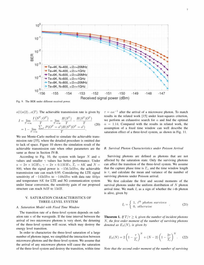
the simulation result of symbol error rate at the differentnoise temperature Te and period duration number N is shownin Fig. 9. For a given thermal noise temperature, we adjustthe period number N , which is inversely proportional to thebandwidth, such that the thermal noise photon number isequivalent to a 10mK thermal noise source. According toFig. 9, a system with a larger κ has lower BER because ofthe more sensitive input signal response. At the same thermalnoise level, the system with large N has lower BER. We adoptκ = 2π × 1GHz, Te = 8K and N = 800 to calculate thesensitivity. When N = 800, the bit rate is 1/(N × (Tc+∆o+tw)) = 1/(800 × (230ns + 35ns + 48ns)) ≈ 4kbps. Whenthe power is −148.3dBm, the bit error rate reaches 10−3.According to the OOK bit error rate formula, the SNR marginis 9.8dB, and thus the normalized sensitivity is −148.3dBm−9.8dB = −158.1dBm for SNR 0dB. The 4G/5G standardsystem working under (4kbps, 8K) has a sensitivity gain10log10(2.2M/4k)dB + 10log10(300/8)dB ≈ 43dB whenlinearly converted from (2.2Mbps, 300K). Considering theLTE signal sensitivity of −100dBm to −105dBm with datarate 2.2Mbps for LTE and 5G communication system [36], thesensitivity of 4G/5G system under the same temperature anddata rate is −143dBm to −148dBm. The sensitivity gain ofour proposed structure can reach 10dB to 15dB. Since targetBER 10−3 is considered under low temperature and data rate,we focus on singal power regime below −145dBm.
C. Achievable Transmission Rate
Assume that the symbol sequence in continuous detectionis ST = s(1)s(2)...s(T ) and the output sequence is OT =
7
-156 -155 -154 -153 -152 -151 -150 -149 -148 -147
Received signal power (dBm)
10-5
10-4
10-3
10-2
10-1
100
BE
R
Te=4K, N=400, /2 =20MHz
Te=4K, N=400, /2 =1GHz
Te=6K, N=600, /2 =20MHz
Te=6K, N=600, /2 =1GHz
Te=8K, N=800, /2 =20MHz
Te=8K, N=800, /2 =1GHz
Fig. 9. The BER under different received power.
o(1)o(2)...o(T ). The achievable transmission rate is given by
I = limT→∞
I(ST ;OT
)T
= limT→∞
H(ST )
T− H(ST |OT )
T
= 1− limT→∞
∑ot P (OT = ot)H(ST |OT = ot)
T.
(20)
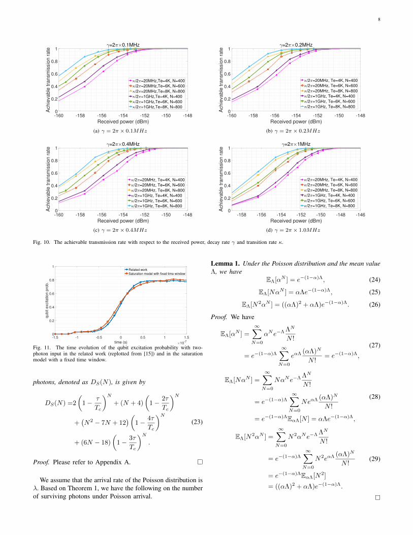
We use Monte-Carlo method to simulate the achievable trans-mission rate [35], where the detailed procedure is omitted dueto lack of space. Figure 10 shows the simulation result of theachievable transmission rate when other parameters are thesame as those in Section IV-B.
According to Fig. 10, the system with larger N and κvalues and smaller γ values has better performance. Underκ = 2π × 1GHz, γ = 2π × 0.1MHz, Te = 8K and N =800, when the signal power is −156.5dBm, the achievabletransmission rate can reach 0.95. Considering the LTE signalsensitivity of −143dBm to −148dBm with data rate 4kbpsand temperature 8K for LTE and 5G communication systemunder linear conversion, the sensitivity gain of our proposedstructure can reach 8dB to 13dB.
V. SATURATION CHARACTERISTICS OFTHREE-LEVEL SYSTEM
A. Saturation Model with Fixed Time Window
The transition rate of a three-level system depends on radi-ation rate κ of the waveguide. If the time interval between thearrival of two microwave photons is very short, the detuningof the three-level system will occur, which may destroy theenergy level transition.
In order to characterize the three-level saturation of a largenumber of photons input, we simplified the interaction betweenmicrowave photons and the three-level system. We assume thatthe arrival of any microwave photon will cause the saturationof the three-level system and destroy the transition, within time
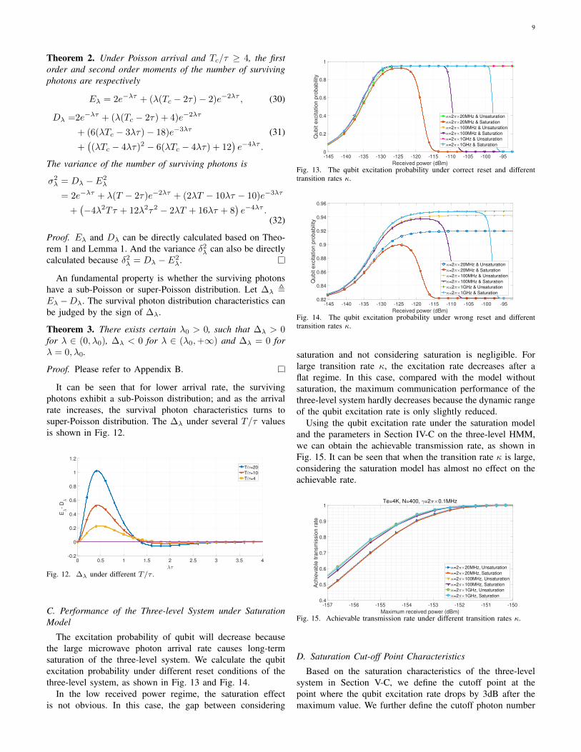
τ = ακ−1 after the arrival of a microwave photon. To matchresults in the related work [15] under least-squares criterion,we perform an exhaustive search for α and find the optimalα = 1.14. Compared with the results in related work, theassumption of a fixed time window can well describe thesaturation effect of a three-level system, as shown in Fig. 11.
B. Survival Photon Characteristics under Poisson Arrival
Surviving photons are defined as photons that are notaffected by the saturation state. Only the surviving photonscan affect the transition of the three-level system. We assumethat the capture phase time is Tc, and the time window lengthis τ , and calculate the mean and variance of the number ofsurviving photons under Poisson arrival.
We first calculate the first and second moments of thesurvival photons under the uniform distribution of N photonarrival time. We mark Ii as a sign of whether the i-th photonis alive, given by
Ii =
1, ith photon survives0, otherwise
. (21)
Theorem 1. If T/τ ≥ 4, given the number of incident photonsN , the first order moment of the number of surviving photonsdenoted as ES(N), is given by
ES(N) = 2
(1− τ
Tc
)N+ (N − 2)
(1− 2τ
Tc
)N. (22)
Note that the second order moment of the number of surviving
8
-160 -158 -156 -154 -152 -150 -148
Received power (dBm)
0
0.2
0.4
0.6
0.8
1A
chie
vable
tra
nsm
issio
n r
ate
=2 0.1MHz
/2 =20MHz,Te=4K, N=400
/2 =20MHz,Te=6K, N=600
/2 =20MHz,Te=8K, N=800
/2 =1GHz,Te=4K, N=400
/2 =1GHz,Te=6K, N=600
/2 =1GHz,Te=8K, N=800
(a) γ = 2π × 0.1MHz
-160 -158 -156 -154 -152 -150 -148
Received power (dBm)
0
0.2
0.4
0.6
0.8
1
Achie
vable
tra
nsm
issio
n r
ate
=2 0.2MHz
/2 =20MHz, Te=4K, N=400
/2 =20MHz, Te=6K, N=600
/2 =20MHz, Te=8K, N=800
/2 =1GHz, Te=4K, N=400
/2 =1GHz, Te=6K, N=600
/2 =1GHz, Te=8K, N=800
(b) γ = 2π × 0.2MHz
-160 -158 -156 -154 -152 -150 -148
Received power (dBm)
0
0.2
0.4
0.6
0.8
1
Achie
vable
tra
nsm
issio
n r
ate
=2 0.4MHz
/2 =20MHz, Te=4K, N=400
/2 =20MHz, Te=6K, N=600
/2 =20MHz, Te=8K, N=800
/2 =1GHz, Te=4K, N=400
/2 =1GHz, Te=6K, N=600
/2 =1GHz, Te=8K, N=800
(c) γ = 2π × 0.4MHz
-158 -156 -154 -152 -150 -148 -146
Received power (dBm)
0
0.2
0.4
0.6
0.8
1
Achie
vable
tra
nsm
issio
n r
ate
=2 1MHz
/2 =20MHz, Te=4K, N=400
/2 =20MHz, Te=6K, N=600
/2 =20MHz, Te=8K, N=800
/2 =1GHz, Te=4K, N=400
/2 =1GHz, Te=6K, N=600
/2 =1GHz, Te=8K, N=800
(d) γ = 2π × 1.0MHz
Fig. 10. The achievable transmission rate with respect to the received power, decay rate γ and transition rate κ.
-1.5 -1 -0.5 0 0.5 1 1.5
time (s) 10-7
0
0.2
0.4
0.6
0.8
1
qubit e
xcitation p
rob.
Related work
Saturation model with fixed time window
Fig. 11. The time evolution of the qubit excitation probability with two-photon input in the related work (replotted from [15]) and in the saturationmodel with a fixed time window.
photons, denoted as DS(N), is given by
DS(N) =2
(1− τ
Tc
)N+ (N + 4)
(1− 2τ
Tc
)N+(N2 − 7N + 12
)(1− 4τ
Tc
)N+ (6N − 18)
(1− 3τ
Tc
)N.
(23)
Proof. Please refer to Appendix A.
We assume that the arrival rate of the Poisson distribution isλ. Based on Theorem 1, we have the following on the numberof surviving photons under Poisson arrival.
Lemma 1. Under the Poisson distribution and the mean valueΛ, we have
EΛ[αN ] = e−(1−α)Λ, (24)
EΛ[NαN ] = αΛe−(1−α)Λ, (25)
EΛ[N2αN ] = ((αΛ)2 + αΛ)e−(1−α)Λ. (26)
Proof. We have
EΛ[αN ] =
∞∑N=0
αNe−Λ ΛN
N !
= e−(1−α)Λ∞∑N=0
eαΛ (αΛ)N
N != e−(1−α)Λ,
(27)
EΛ[NαN ] =
∞∑N=0
NαNe−Λ ΛN
N !
= e−(1−α)Λ∞∑N=0
NeαΛ (αΛ)N
N !
= e−(1−α)ΛEαΛ[N ] = αΛe−(1−α)Λ,
(28)
EΛ[N2αN ] =
∞∑N=0
N2αNe−Λ ΛN
N !
= e−(1−α)Λ∞∑N=0
N2eαΛ (αΛ)N
N !
= e−(1−α)ΛEαΛ[N2]
= ((αΛ)2 + αΛ)e−(1−α)Λ.
(29)
9
Theorem 2. Under Poisson arrival and Tc/τ ≥ 4, the firstorder and second order moments of the number of survivingphotons are respectively
Eλ = 2e−λτ + (λ(Tc − 2τ)− 2)e−2λτ , (30)
Dλ =2e−λτ + (λ(Tc − 2τ) + 4)e−2λτ
+ (6(λTc − 3λτ)− 18)e−3λτ
+((λTc − 4λτ)2 − 6(λTc − 4λτ) + 12
)e−4λτ .
(31)
The variance of the number of surviving photons is
σ2λ = Dλ − E2
λ
= 2e−λτ + λ(T − 2τ)e−2λτ + (2λT − 10λτ − 10)e−3λτ
+(−4λ2Tτ + 12λ2τ2 − 2λT + 16λτ + 8
)e−4λτ .
(32)
Proof. Eλ and Dλ can be directly calculated based on Theo-rem 1 and Lemma 1. And the variance δ2
λ can also be directlycalculated because δ2
λ = Dλ − E2λ.
An fundamental property is whether the surviving photonshave a sub-Poisson or super-Poisson distribution. Let ∆λ ,Eλ −Dλ. The survival photon distribution characteristics canbe judged by the sign of ∆λ.
Theorem 3. There exists certain λ0 > 0, such that ∆λ > 0for λ ∈ (0, λ0), ∆λ < 0 for λ ∈ (λ0,+∞) and ∆λ = 0 forλ = 0, λ0.
Proof. Please refer to Appendix B.
It can be seen that for lower arrival rate, the survivingphotons exhibit a sub-Poisson distribution; and as the arrivalrate increases, the survival photon characteristics turns tosuper-Poisson distribution. The ∆λ under several T/τ valuesis shown in Fig. 12.
0 0.5 1 1.5 2 2.5 3 3.5 4-0.2
0
0.2
0.4
0.6
0.8
1
1.2
E-
D
T/ =20
T/ =10
T/ =4
Fig. 12. ∆λ under different T/τ .
C. Performance of the Three-level System under SaturationModel
The excitation probability of qubit will decrease becausethe large microwave photon arrival rate causes long-termsaturation of the three-level system. We calculate the qubitexcitation probability under different reset conditions of thethree-level system, as shown in Fig. 13 and Fig. 14.
In the low received power regime, the saturation effectis not obvious. In this case, the gap between considering
-145 -140 -135 -130 -125 -120 -115 -110 -105 -100 -95
Received power (dBm)
0
0.2
0.4
0.6
0.8
1
Qubit e
xcitation p
robabili
ty
=2 20MHz & Unsaturation
=2 20MHz & Saturation
=2 100MHz & Unsaturation
=2 100MHz & Saturation
=2 1GHz & Unsaturation
=2 1GHz & Saturation
Fig. 13. The qubit excitation probability under correct reset and differenttransition rates κ.
-145 -140 -135 -130 -125 -120 -115 -110 -105 -100 -95
Received power (dBm)
0.82
0.84
0.86
0.88
0.9
0.92
0.94
0.96
Qubit e
xcitation p
robabili
ty
=2 20MHz & Unsaturation
=2 20MHz & Saturation
=2 100MHz & Unsaturation
=2 100MHz & Saturation
=2 1GHz & Unsaturation
=2 1GHz & Saturation
Fig. 14. The qubit excitation probability under wrong reset and differenttransition rates κ.
saturation and not considering saturation is negligible. Forlarge transition rate κ, the excitation rate decreases after aflat regime. In this case, compared with the model withoutsaturation, the maximum communication performance of thethree-level system hardly decreases because the dynamic rangeof the qubit excitation rate is only slightly reduced.
Using the qubit excitation rate under the saturation modeland the parameters in Section IV-C on the three-level HMM,we can obtain the achievable transmission rate, as shown inFig. 15. It can be seen that when the transition rate κ is large,considering the saturation model has almost no effect on theachievable rate.
-157 -156 -155 -154 -153 -152 -151 -150
Maximum received power (dBm)
0.4
0.5
0.6
0.7
0.8
0.9
1
Achie
vable
tra
nsm
issio
n r
ate
Te=4K, N=400, =2 0.1MHz
=2 20MHz, Unsaturation
=2 20MHz, Saturation
=2 100MHz, Unsaturation
=2 100MHz, Saturation
=2 1GHz, Unsaturation
=2 1GHz, Saturation
Fig. 15. Achievable transmission rate under different transition rates κ.
D. Saturation Cut-off Point Characteristics
Based on the saturation characteristics of the three-levelsystem in Section V-C, we define the cutoff point at thepoint where the qubit excitation rate drops by 3dB after themaximum value. We further define the cutoff photon number
10
as the mean photon number at the saturation cutoff point. Thecutoff photon number under different decay rates κ and capturetime Tc is shown in Fig. 16. The number of cut-off photonsunder different decay rate γ is shown in Fig. 17.
0 200 400 600 800 1000 1200 1400 1600 1800 2000
/2 (MHz)
0
2000
4000
6000
8000
10000
12000
Cuto
ff p
hoto
n n
um
ber
Tc=80ns
Tc=130ns
Tc=230ns
Fig. 16. Cutoff photon number under different transition rates κ and capturetime Tc.
0 0.1 0.2 0.3 0.4 0.5 0.6 0.7 0.8 0.9 1
/(2 MHz)
102
103
104
105
Cuto
ff p
hoto
n n
um
ber
=2 1GHz
=2 100MHz
=2 20MHz
Fig. 17. Cutoff photon number under different decay rates γ and transitionrates κ.
It can be seen that γ has little effect on the cut-off pointin the common range of γ. On the other hand, κ determinesthe normalized saturation time window number, and furtherdetermines the cut-off photon number to a large extent. Plottedagainst κTc in γ = 0, the cutoff points under different valuesof Tc overlap very well, as shown in Fig. 18. We further useκTc as the independent variable for fitting, and the fitting resultis shown in Fig. 18. When κTc is large, the fitting result isvery close to the simulation result. The fitted equation is givenby,
ncutoff = 1.457 (kTc)1.132 − 0.8766. (33)
101
102
103
Tc
101
102
103
104
Cuto
ff p
hoto
n n
um
ber
Tc=80ns
Tc=130ns
Tc=230ns
fitting
Fig. 18. Cutoff photon number with κTc as the horizontal axis and the fittingresult.
VI. CONCLUSION
We have adopted artificial Λ-type three level system with su-perconducting devices for microwave signal detection. Basedon the state transition principles, we have proposed a statisticalmodel for microwave signal detection. We have also inves-tigated the achievable transmission rate and signal detectionbased on the statistical model. It is predicted that high detec-tion sensitivity can be achieved by the proposed structure. Wefurther studied the saturation characteristics of the three-levelsystem and showed that it has no effect on the very weakmicrowave communication.
The three-level system has great application potential inthe field of outer space communication due to significantlyhigh sensitivity at low temperature, for example, deployedon spacecraft or satellites. Higher transmission rate can beachieved via deploying parallel three-level systems centeredat separated frequencies.
In future work, we will study the communication signalprocessing of three-level systems, including symbol synchro-nization and the saturation problem under high received power.In addition, receiver device fabrication and real experimentsis another major endeavor.
APPENDIX
A. Proof of Theorem 1
We have the following
ES(N) = E
(N∑i=1
Ii
)= NE (I1) , (34)
E (I1) represents the probability of survival of a uniformlydistributed photon. So E (I1) is given by
E (I1) =2
Tc
∫ τ
0
(1− t+ τ
Tc
)N−1
dt
+Tc − 2τ
Tc
(1− 2τ
Tc
)N−1
.
(35)
Thus we have that
ES(N) = NE (I1)
= 2
(1− τ
Tc
)N+ (N − 2)
(1− 2τ
Tc
)N.
(36)
And the second moment is given by
DS(N) = E
( N∑i=1
Ii
)2
= NE(I21
)+N(N − 1)E (I1I2) .
(37)
Obviously we have
NE(I21
)= NE (I1)
= 2
(1− τ
Tc
)N+ (N − 2)
(1− 2τ
Tc
)N.
(38)
E (I1I2) represents the probability that two independentphotons that obey a uniform distribution are surviving photons.Assume that the arrival times of the two photons are t1 and
11
t2 respectively, and t1 ≤ t2. According to the value of t1, wedivide E (I1I2) into four parts, i.e.,
E (I1I2) =2
T 2c
(A+B + C +D). (39)
1) 0 ≤ t1 < τ
A =2
∫ τ
0
dt1
∫ t1+2τ
t1+τ
dt2
(1− t2 + τ
Tc
)N−2
+
∫ τ
0
dt1
∫ Tc−τ
t1+2τ
dt2
(1− t1 + 3τ
Tc
)N−2
.
(40)
Further, we have
2
T 2c
A =4
N(N − 1)
(Tc − 2τ
Tc
)N+
2N − 10
N(N − 1)
(Tc − 3τ
Tc
)N+
6− 2N
N(N − 1)
(Tc − 4τ
Tc
)N.
(41)
2) τ ≤ t1 < Tc − 3τ
B =2
∫ Tc−3τ
τ
dt1
∫ t1+2τ
t1+τ
dt2
(1− t2 − t1 + 2τ
Tc
)N−2
+
∫ Tc−3τ
τ
dt1
∫ Tc−τ
t1+2τ
dt2
(1− 4τ
Tc
)N−2
.
(42)Further, we have
2
T 2c
B =4
N − 1
(1− 4τ
Tc
)(1− 3τ
Tc
)N−1
+N − 5
N − 1
(1− 4τ
Tc
)N.
(43)
3) Tc − 3τ ≤ t1 < Tc − 2τ
C =2
∫ Tc−2τ
Tc−3τ
dt1
∫ Tc−τ
t1+τ
dt2
(1− t2 − t1 + 2τ
Tc
)N−2
+
∫ Tc−2τ
Tc−3τ
dt1
∫ t1+2τ
Tc−τdt2
(t1 − τTc
)N−2
.
(44)Further, we have
2
T 2c
C =6Nτ − 6TcN(N − 1)Tc
(1− 3τ
Tc
)N−1
+6
N(N − 1)
(1− 4τ
Tc
)N.
(45)
4) Tc − 2τ ≤ t1 < Tc − τ
D =
∫ Tc−τ
Tc−2τ
dt1
∫ Tc
t1+τ
dt2
(1− Tc − t1 + τ
Tc
)N−2
.
(46)Further, we have
2
T 2c
D =2
N(N − 1)
[(1− 2τ
Tc
)N−(
1− 3τ
Tc
)N]
− 2τ
(N − 1)Tc
(1− 3τ
Tc
)N−1
.
(47)
According to the above results, the second moment is givenby
DN =2
(1− τ
Tc
)N+ (N + 4)
(1− 2τ
Tc
)N+(N2 − 7N + 12
)(1− 4τ
Tc
)N+ (6N − 18)
(1− 3τ
Tc
)N.
(48)
B. Proof of Theorem 3
We define a = λτ , β = Tc/τ ≥ 4 and S(a) = ∆λe4a. And
we have the following
S(a) =− 2e2a − [(2β − 10)a− 10]ea + (4β − 12)a2
+ (2β − 16)a− 8,(49)
dS
da=− 4e2a − [(2β − 10)(a+ 1)− 10]ea
+ (8β − 24)a+ (2β − 16),(50)
d2S
da2= −8e2a− [(2β−10)(a+2)−10]ea+(8β−24), (51)
dkS
dak= −2k+1e2a − [(2β − 10)(a+ k)− 10]ea
, pk(a)ea, k ≥ 3.
(52)When λ = 0, we have S(0) = 0, S(1)(0) = 0 and S(2)(0) =
4β − 2 > 0. In order to illustrate the value of S with a > 0,we further prove some theorems of pk(a).
Lemma 2. If k ≥ 1 and pk(0) ≤ 0, we have pk(a) ≤ 0 witha ≥ 0.
Proof. we have
pk(0) = −2k+1 − (2M − 10)k + 10 ≤ 0, (53)
pk(a)− pk(0) = −2k+1 (ea − 1)− (2M − 10)a
≤ −(2k+1 + 2M − 10
)a.
(54)
If 2M − 10 ≤ 0, we have the following
−2k+1−(2M−10) < −2k+1−(2M−10)k+10 ≤ 0, (55)
pk(a)− pk(0) ≤ −(2k+1 + 2M − 10
)a ≤ 0. (56)
If 2M−10 > 0, pk(a)−pk(0) ≤ 0 obviously. Thus, we prove
pk(a) = pk(0) + pk(a)− pk(0) ≤ 0. (57)
Because of limk→∞ pk(0) → −∞ and lima→+∞ pk(a) →−∞, we let k∗ be the smallest positive integer such thatpk(a) < 0. If k∗ ≥ 4, S(3) is positive first and then negativeas a increases. When k < 4, S(3) ≤ 0 always holds. In otherwords, S, S(1) and S(2) are all positive first and then negativewith a > 0.
12
REFERENCES
[1] V. F. Vdovin, V. G. Grachev, S. Y. Dryagin, A. I. Eliseev, R. K.Kamaletdinov, D. V. Korotaev, I. V. Lesnov, M. A. Mansfeld, E. L.Pevzner, V. G. Perminov, A. M. Pilipenko, B. D. Sapozhnikov, andV. P. Saurin, “Cryogenically cooled low-noise amplifier for radio-astronomical observations and centimeter-wave deep-space communi-cations systems,” Astrophysical Bulletin, vol. 71, no. 1, pp. 125–128,Jan 2016.
[2] B. Mathason, M. M. Albert, D. Engin, H. Cao, K. G. Petrillo, J. Hwang,K. Le, K. Puffenberger, S. Litvinovitch, M. Storm, and R. Utano,“CubeSat lasercom optical terminals for near-Earth to deep space com-munications,” in Free-Space Laser Communications XXXI, H. Hemmatiand D. M. Boroson, Eds., vol. 10910, International Society for Opticsand Photonics. SPIE, 2019, pp. 24 – 29.
[3] M. D. Shaw, F. Marsili, A. D. Beyer, J. A. Stern, G. V. Resta,P. Ravindran, S. Chang, J. Bardin, D. S. Russell, J. W. Gin, F. D.Patawaran, V. B. Verma, R. P. Mirin, S. W. Nam, and W. H. Farr,“Arrays of wsi superconducting nanowire single photon detectors fordeep-space optical communications,” in 2015 Conference on Lasers andElectro-Optics (CLEO), 2015, pp. 1–2.
[4] H. Terai, S. Miki, T. Yamashita, S. Miyajima, and M. Yabuno, “Su-perconducting nanowire single-photon detectors for future optical com-munications,” in 2018 Optical Fiber Communications Conference andExposition (OFC), 2018, pp. 1–3.
[5] M. E. Grein, A. J. Kerman, E. A. Dauler, M. M. Willis, B. Romkey,R. J. Molnar, B. S. Robinson, D. V. Murphy, and D. M. Boroson,“An optical receiver for the Lunar Laser Communication Demonstrationbased on photon-counting superconducting nanowires,” in AdvancedPhoton Counting Techniques IX, M. A. Itzler and J. C. Campbell, Eds.,vol. 9492, International Society for Optics and Photonics. SPIE, 2015,pp. 11 – 16.
[6] C. A. Mears, Q. Hu, P. L. Richards, A. H. Worsham, D. E. Prober,and A. V. Raisanen, “Quantum-limited heterodyne detection of mil-limeter waves using superconducting tantalum tunnel junctions,” AppliedPhysics Letters, vol. 57, no. 23, pp. 2487–2489, 1990.
[7] P. L. Richards and Q. Hu, “Superconducting components for infraredand millimeter-wave receivers,” Proceedings of the IEEE, vol. 77, no. 8,pp. 1233–1246, 1989.
[8] M. J. Wengler, N. Dubash, G. Pance, and R. E. Miller, “Josephson effectgain and noise in sis mixers,” IEEE Transactions on Microwave Theoryand Techniques, vol. 40, no. 5, pp. 820–826, 1992.
[9] M. J. Wengler, “Submillimeter-wave detection with superconductingtunnel diodes,” Proceedings of the IEEE, vol. 80, no. 11, pp. 1810–1826, 1992.
[10] Y.-F. Chen, D. Hover, S. Sendelbach, L. Maurer, S. T. Merkel, E. J.Pritchett, F. K. Wilhelm, and R. McDermott, “Microwave photon counterbased on josephson junctions,” Phys. Rev. Lett., vol. 107, p. 217401,2011.
[11] T. Joas, A. M. Waeber, G. Braunbeck, and F. Reinhard, “Quantumsensing of weak radio-frequency signals by pulsed mollow absorptionspectroscopy,” Nature Communications, vol. 8, no. 1, p. 964, 2017.
[12] B. Yang, Y. Dong, Z. Hu, G. Liu, Y. Wang, and G. Du, “Noninvasiveimaging method of microwave near field based on solid-state quantumsensing,” IEEE Transactions on Microwave Theory and Techniques,vol. 66, no. 5, pp. 2276–2283, 2018.
[13] E. Flurin, N. Roch, J. D. Pillet, F. Mallet, and B. Huard, “Superconduct-ing quantum node for entanglement and storage of microwave radiation,”Phys. Rev. Lett., vol. 114, p. 090503, Mar 2015.
[14] J. Majer, J. M. Chow, J. M. Gambetta, J. Koch, B. R. Johnson,J. A. Schreier, L. Frunzio, D. I. Schuster, A. A. Houck, A. Wallraff,A. Blais, M. H. Devoret, S. M. Girvin, and R. J. Schoelkopf, “Couplingsuperconducting qubits via a cavity bus,” Nature, vol. 449, no. 7161,pp. 443–447, Sep 2007.
[15] K. Koshino, K. Inomata, Z. Lin, Y. Nakamura, and T. Yamamoto,“Theory of microwave single-photon detection using an impedance-matched Λ system,” Phys. Rev. A, vol. 91, p. 043805, Apr 2015.
[16] Q. A. Turchette, C. J. Hood, W. Lange, H. Mabuchi, and H. J. Kimble,“Measurement of conditional phase shifts for quantum logic,” Phys. Rev.Lett., vol. 75, pp. 4710–4713, Dec 1995.
[17] K. P. Nayak, P. N. Melentiev, M. Morinaga, F. L. Kien, V. I. Balykin, andK. Hakuta, “Optical nanofiber as an efficient tool for manipulating andprobing atomic fluorescence,” Opt. Express, vol. 15, no. 9, pp. 5431–5438, Apr 2007.
[18] I. Fushman, D. Englund, A. Faraon, N. Stoltz, P. Petroff, andJ. Vuckovic, “Controlled phase shifts with a single quantum dot,”Science, vol. 320, no. 5877, pp. 769–772, 2008.
[19] M. Fujiwara, K. Toubaru, T. Noda, H.-Q. Zhao, and S. Takeuchi, “Highlyefficient coupling of photons from nanoemitters into single-mode opticalfibers,” Nano Letters, vol. 11, no. 10, pp. 4362–4365, Oct 2011.
[20] R. Yalla, F. Le Kien, M. Morinaga, and K. Hakuta, “Efficient channelingof fluorescence photons from single quantum dots into guided modes ofoptical nanofiber,” Phys. Rev. Lett., vol. 109, p. 063602, Aug 2012.
[21] A. Reiserer, N. Kalb, G. Rempe, and S. Ritter, “A quantum gate betweena flying optical photon and a single trapped atom,” Nature, vol. 508, no.7495, pp. 237–240, Apr 2014.
[22] T. G. Tiecke, J. D. Thompson, N. P. de Leon, L. R. Liu, V. Vuletic,and M. D. Lukin, “Nanophotonic quantum phase switch with a singleatom,” Nature, vol. 508, no. 7495, pp. 241–244, Apr 2014.
[23] M. Arcari, I. Sollner, A. Javadi, S. Lindskov Hansen, S. Mahmoodian,J. Liu, H. Thyrrestrup, E. H. Lee, J. D. Song, S. Stobbe, and P. Lodahl,“Near-unity coupling efficiency of a quantum emitter to a photoniccrystal waveguide,” Phys. Rev. Lett., vol. 113, p. 093603, Aug 2014.
[24] R. Mitsch, C. Sayrin, B. Albrecht, P. Schneeweiss, and A. Rauschenbeu-tel, “Quantum state-controlled directional spontaneous emission of pho-tons into a nanophotonic waveguide,” Nature Communications, vol. 5,no. 1, p. 5713, Dec 2014.
[25] J. M. Raimond, M. Brune, and S. Haroche, “Manipulating quantumentanglement with atoms and photons in a cavity,” Rev. Mod. Phys.,vol. 73, pp. 565–582, Aug 2001.
[26] A. Wallraff, D. I. Schuster, A. Blais, L. Frunzio, R.-. S. Huang, J. Majer,S. Kumar, S. M. Girvin, and R. J. Schoelkopf, “Strong coupling ofa single photon to a superconducting qubit using circuit quantumelectrodynamics,” Nature, vol. 431, no. 7005, pp. 162–167, Sep 2004.
[27] M. Hofheinz, H. Wang, M. Ansmann, R. C. Bialczak, E. Lucero,M. Neeley, A. D. O’Connell, D. Sank, J. Wenner, J. M. Martinis, andA. N. Cleland, “Synthesizing arbitrary quantum states in a supercon-ducting resonator,” Nature, vol. 459, no. 7246, pp. 546–549, May 2009.
[28] K. Inomata, Z. Lin, K. Koshino, W. D. Oliver, J.-S. Tsai, T. Yamamoto,and Y. Nakamura, “Single microwave-photon detector using an artificialΛ-type three-level system,” Nature communications, vol. 7, no. 1, pp.1–7, 2016.
[29] K. Inomata, T. Yamamoto, P.-M. Billangeon, Y. Nakamura, and J. S.Tsai, “Large dispersive shift of cavity resonance induced by a super-conducting flux qubit in the straddling regime,” Phys. Rev. B, vol. 86,p. 140508, Oct 2012.
[30] T. Yamamoto, K. Inomata, K. Koshino, P.-M. Billangeon, Y. Nakamura,and J. S. Tsai, “Superconducting flux qubit capacitively coupled to anLC resonator,” New Journal of Physics, vol. 16, no. 1, p. 015017, jan2014.
[31] K. Inomata, K. Koshino, Z. R. Lin, W. D. Oliver, J. S. Tsai, Y. Nakamura,and T. Yamamoto, “Microwave down-conversion with an impedance-matched Λ system in driven circuit qed,” Phys. Rev. Lett., vol. 113, p.063604, Aug 2014.
[32] K. Koshino, K. Inomata, T. Yamamoto, and Y. Nakamura, “Theoryof deterministic down-conversion of single photons occurring at animpedance-matched Λ system,” New Journal of Physics, vol. 15, no. 11,p. 115010, nov 2013.
[33] ——, “Implementation of an impedance-matched Λ system by dressed-state engineering,” Phys. Rev. Lett., vol. 111, p. 153601, Oct 2013.
[34] Z. Lin, K. Inomata, K. Koshino, W. Oliver, Y. Nakamura, J.-S. Tsai,and T. Yamamoto, “Josephson parametric phase-locked oscillator andits application to dispersive readout of superconducting qubits,” Naturecommunications, vol. 5, no. 1, pp. 1–6, 2014.
[35] X. Liu, C. Gong, B. Liu, S. Li, and Z. Xu, “Hidden markov model basedsignal characterization for weak light communication,” IEEE Journal ofLightwave Technology, vol. 36, no. 9, pp. 1730–1738, 2018.
[36] U. Equipment, “radio transmission and reception (release 12), 3gpp ts36.101, v12. 13.0, 2016.”