
Proline Promag 50W, 53W
47
Products Solutions Services 0TI00046D/06/EN/13.17 71385969 Technical Information Proline Promag 50W, 53W Electromagnetic flowmeter Flow measurement of liquids in water or wastewater applications Application Electromagnetic flowmeter for bidirectional measurement of liquids with a minimum conductivity of 5 μS/cm: • Drinking water • Wastewater • Sewage sludge • Flow measurement up to 110 000 m³/h (484 315 gal/min) • Fluid temperature up to +80 °C (+176 °F) • Process pressures up to 40 bar (580 psi) • Lengths in accordance with DVGW/ISO Application-specific lining of the measuring pipe from polyurethane or hard rubber with the following drinking water permissions: • KTW • WRAS • NSF • ACS Approvals for hazardous area: • ATEX • IECEx • FM • CSA • NEPSI Connection to process control system: • HART • PROFIBUS DP/PA • FOUNDATION Fieldbus • Modbus RS485 Your benefits Promag measuring devices offer you cost-effective flow measurement with a high degree of accuracy for a wide range of process conditions. The uniform Proline transmitter concept comprises: • Modular device and operating concept resulting in a higher degree of efficiency • Software options for batching, electrode cleaning and for measuring pulsating flow • High degree of reliability and measuring stability • Uniform operating concept The tried-and-tested Promag sensors offer: • No pressure loss • Not sensitive to vibrations • Simple installation and commissioning
Transcript of Proline Promag 50W, 53W

Products Solutions Services0TI00046D/06/EN/13.1771385969
Technical InformationProline Promag 50W, 53WElectromagnetic flowmeter
Flow measurement of liquids in water or wastewater applications
Application
Electromagnetic flowmeter for bidirectional measurement of liquids with a minimum conductivity of 5 μS/cm:• Drinking water• Wastewater• Sewage sludge
• Flow measurement up to 110000 m³/h (484315 gal/min)• Fluid temperature up to +80 °C (+176 °F)• Process pressures up to 40 bar (580 psi)• Lengths in accordance with DVGW/ISO
Application-specific lining of the measuring pipe from polyurethane or hard rubber with the following drinking water permissions:• KTW• WRAS• NSF• ACS
Approvals for hazardous area:• ATEX• IECEx• FM• CSA• NEPSI
Connection to process control system:• HART• PROFIBUS DP/PA• FOUNDATION Fieldbus• Modbus RS485
Your benefitsPromag measuring devices offer you cost-effective flow measurement with a high degree of accuracy for a wide range of process conditions.
The uniform Proline transmitter concept comprises:• Modular device and operating concept resulting in a higher
degree of efficiency• Software options for batching, electrode cleaning and for
measuring pulsating flow• High degree of reliability and measuring stability• Uniform operating concept
The tried-and-tested Promag sensors offer:• No pressure loss• Not sensitive to vibrations• Simple installation and commissioning
Proline Promag 50W, 53W
2 Endress+Hauser
Table of contents
Function and system design . . . . . . . . . . . . . . . . . . . . . .3Measuring principle . . . . . . . . . . . . . . . . . . . . . . . . . . . . . . . . . . . 3Measuring system . . . . . . . . . . . . . . . . . . . . . . . . . . . . . . . . . . . . . 3
Input . . . . . . . . . . . . . . . . . . . . . . . . . . . . . . . . . . . . . . . . . .4Measured variable . . . . . . . . . . . . . . . . . . . . . . . . . . . . . . . . . . . . . 4Measuring ranges . . . . . . . . . . . . . . . . . . . . . . . . . . . . . . . . . . . . . 4Operable flow range . . . . . . . . . . . . . . . . . . . . . . . . . . . . . . . . . . . 4Input signal . . . . . . . . . . . . . . . . . . . . . . . . . . . . . . . . . . . . . . . . . . . 4
Output . . . . . . . . . . . . . . . . . . . . . . . . . . . . . . . . . . . . . . . . .4Output signal . . . . . . . . . . . . . . . . . . . . . . . . . . . . . . . . . . . . . . . . . 4Signal on alarm . . . . . . . . . . . . . . . . . . . . . . . . . . . . . . . . . . . . . . . 6Load . . . . . . . . . . . . . . . . . . . . . . . . . . . . . . . . . . . . . . . . . . . . . . . . . 6Low flow cutoff . . . . . . . . . . . . . . . . . . . . . . . . . . . . . . . . . . . . . . . 6Galvanic isolation . . . . . . . . . . . . . . . . . . . . . . . . . . . . . . . . . . . . . 6Switching output . . . . . . . . . . . . . . . . . . . . . . . . . . . . . . . . . . . . . . 6
Power supply . . . . . . . . . . . . . . . . . . . . . . . . . . . . . . . . . . .7Terminal assignment . . . . . . . . . . . . . . . . . . . . . . . . . . . . . . . . . . 7Supply voltage . . . . . . . . . . . . . . . . . . . . . . . . . . . . . . . . . . . . . . . . 8Power consumption . . . . . . . . . . . . . . . . . . . . . . . . . . . . . . . . . . . . 8Power supply failure . . . . . . . . . . . . . . . . . . . . . . . . . . . . . . . . . . . 8Electrical connection, measuring unit . . . . . . . . . . . . . . . . . . . . . 9Electrical connection, remote version . . . . . . . . . . . . . . . . . . . . . . . . . . . . . . . . . . . . . . . 10Potential equalization . . . . . . . . . . . . . . . . . . . . . . . . . . . . . . . . . 10Cable entries . . . . . . . . . . . . . . . . . . . . . . . . . . . . . . . . . . . . . . . . . 11Remote version cable specifications . . . . . . . . . . . . . . . . . . . . . 12
Performance characteristics . . . . . . . . . . . . . . . . . . . . 13Reference operating conditions . . . . . . . . . . . . . . . . . . . . . . . . . 13Maximum measured error . . . . . . . . . . . . . . . . . . . . . . . . . . . . . 13Repeatability . . . . . . . . . . . . . . . . . . . . . . . . . . . . . . . . . . . . . . . . 13
Installation . . . . . . . . . . . . . . . . . . . . . . . . . . . . . . . . . . . 14Mounting location . . . . . . . . . . . . . . . . . . . . . . . . . . . . . . . . . . . . 14Orientation . . . . . . . . . . . . . . . . . . . . . . . . . . . . . . . . . . . . . . . . . . 15Inlet and outlet runs . . . . . . . . . . . . . . . . . . . . . . . . . . . . . . . . . . 16Adapters . . . . . . . . . . . . . . . . . . . . . . . . . . . . . . . . . . . . . . . . . . . . 17Length of connecting cable . . . . . . . . . . . . . . . . . . . . . . . . . . . . 17Foundations, support . . . . . . . . . . . . . . . . . . . . . . . . . . . . . . . . . 18
Environment . . . . . . . . . . . . . . . . . . . . . . . . . . . . . . . . . 19Ambient temperature range . . . . . . . . . . . . . . . . . . . . . . . . . . . 19Storage temperature . . . . . . . . . . . . . . . . . . . . . . . . . . . . . . . . . . 19Degree of protection . . . . . . . . . . . . . . . . . . . . . . . . . . . . . . . . . . 19Shock and vibration resistance . . . . . . . . . . . . . . . . . . . . . . . . . 19Electromagnetic compatibility (EMC) . . . . . . . . . . . . . . . . . . . . 19
Process . . . . . . . . . . . . . . . . . . . . . . . . . . . . . . . . . . . . . . 20Medium temperature range . . . . . . . . . . . . . . . . . . . . . . . . . . . . 20Conductivity . . . . . . . . . . . . . . . . . . . . . . . . . . . . . . . . . . . . . . . . . 20Pressure-temperature ratings . . . . . . . . . . . . . . . . . . . . . . . . . . 20Medium pressure range (nominal pressure) . . . . . . . . . . . . . . 23Pressure tightness . . . . . . . . . . . . . . . . . . . . . . . . . . . . . . . . . . . . 23
Limiting flow . . . . . . . . . . . . . . . . . . . . . . . . . . . . . . . . . . . . . . . . 24Pressure loss . . . . . . . . . . . . . . . . . . . . . . . . . . . . . . . . . . . . . . . . . 26Vibrations . . . . . . . . . . . . . . . . . . . . . . . . . . . . . . . . . . . . . . . . . . . 26
Mechanical construction . . . . . . . . . . . . . . . . . . . . . . . 27Design, dimensions . . . . . . . . . . . . . . . . . . . . . . . . . . . . . . . . . . . 27Weight . . . . . . . . . . . . . . . . . . . . . . . . . . . . . . . . . . . . . . . . . . . . . 40Measuring tube specifications . . . . . . . . . . . . . . . . . . . . . . . . . . 42Material . . . . . . . . . . . . . . . . . . . . . . . . . . . . . . . . . . . . . . . . . . . . 43Fitted electrodes . . . . . . . . . . . . . . . . . . . . . . . . . . . . . . . . . . . . . 43Process connections . . . . . . . . . . . . . . . . . . . . . . . . . . . . . . . . . . 43Surface roughness . . . . . . . . . . . . . . . . . . . . . . . . . . . . . . . . . . . . 43
Operability . . . . . . . . . . . . . . . . . . . . . . . . . . . . . . . . . . . 44Local operation . . . . . . . . . . . . . . . . . . . . . . . . . . . . . . . . . . . . . . 44Language groups . . . . . . . . . . . . . . . . . . . . . . . . . . . . . . . . . . . . . 44Remote operation . . . . . . . . . . . . . . . . . . . . . . . . . . . . . . . . . . . . 44
Certificates and approvals . . . . . . . . . . . . . . . . . . . . . . 45CE mark . . . . . . . . . . . . . . . . . . . . . . . . . . . . . . . . . . . . . . . . . . . . 45C-tick symbol . . . . . . . . . . . . . . . . . . . . . . . . . . . . . . . . . . . . . . . . 45Pressure measuring device approval . . . . . . . . . . . . . . . . . . . . . 45Ex approval . . . . . . . . . . . . . . . . . . . . . . . . . . . . . . . . . . . . . . . . . . 45Other standards and guidelines . . . . . . . . . . . . . . . . . . . . . . . . . 45FOUNDATION Fieldbus certification . . . . . . . . . . . . . . . . . . . . . 45Modbus RS485 certification . . . . . . . . . . . . . . . . . . . . . . . . . . . . 45PROFIBUS DP/PA certification . . . . . . . . . . . . . . . . . . . . . . . . . 45
Ordering information . . . . . . . . . . . . . . . . . . . . . . . . . . 46
Accessories . . . . . . . . . . . . . . . . . . . . . . . . . . . . . . . . . . . 46
Documentation . . . . . . . . . . . . . . . . . . . . . . . . . . . . . . . 46
Registered trademarks . . . . . . . . . . . . . . . . . . . . . . . . . 46
Proline Promag 50W, 53W
Endress+Hauser 3
Function and system design
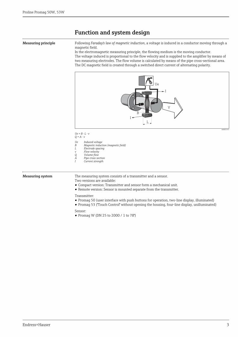
Measuring principle Following Faraday's law of magnetic induction, a voltage is induced in a conductor moving through a magnetic field.In the electromagnetic measuring principle, the flowing medium is the moving conductor.The voltage induced is proportional to the flow velocity and is supplied to the amplifier by means of two measuring electrodes. The flow volume is calculated by means of the pipe cross-sectional area. The DC magnetic field is created through a switched direct current of alternating polarity.
A0003191
Ue = B · L · vQ = A · v
Ue Induced voltageB Magnetic induction (magnetic field)L Electrode spacingv Flow velocityQ Volume flowA Pipe cross-sectionI Current strength
Measuring system The measuring system consists of a transmitter and a sensor.Two versions are available:• Compact version: Transmitter and sensor form a mechanical unit.• Remote version: Sensor is mounted separate from the transmitter.
Transmitter:• Promag 50 (user interface with push buttons for operation, two-line display, illuminated)• Promag 53 ("Touch Control" without opening the housing, four-line display, unilluminated)
Sensor:• Promag W (DN 25 to 2000 / 1 to 78")
Ue
I
I
B
L
V
Proline Promag 50W, 53W
4 Endress+Hauser
Input
Measured variable Flow velocity (proportional to induced voltage)
Measuring ranges Measuring ranges for liquidsTypically v = 0.01 to 10 m/s (0.03 to 33 ft/s) with the specified accuracy
Operable flow range Over 1000 : 1
Input signal Status input (auxiliary input)• U = 3 to 30 V DC, Ri = 5 k, galvanically isolated• Configurable for: totalizer(s) reset, measured value suppression, error-message reset
Status input (auxiliary input) with PROFIBUS DP and Modbus RS485• U = 3 to 30 V DC, Ri = 3 k, galvanically isolated• Switching level: 3 to 30 V DC, independent of polarity• Configurable for: totalizer(s) reset, measured value suppression, error-message reset, batching
start/stop (optional), batch totalizer reset (optional)
Current input (only Promag 53)• Active/passive selectable, galvanically isolated, full scale value selectable, resolution: 3 μA,
temperature coefficient: typ. 0.005% o.r./°C (o.r. = of reading)• Active: 4 to 20 mA, Ri £ 150 W, max. 24 V DC, short-circuit-proof• Passive: 0/4 to 20 mA, Ri < 150 W, max. 30 V DC
Output
Output signal Promag 50
Current outputActive/passive selectable, galvanically isolated, time constant selectable (0.01 to 100 s), full scale value selectable, temperature coefficient: typ. 0.005% o.r./°C (o.r. = of reading), resolution: 0.5 mA• Active: 0/4 to 20 mA, RL < 700 (HART: RL 250 )• Passive: 4 to 20 mA, operating voltage VS: 18 to 30 V DC, Ri 150
Pulse/frequency outputPassive, open collector, 30 V DC, 250 mA, galvanically isolated• Frequency output: full scale frequency 2 to 1000 Hz (fmax = 1250 Hz), on/off ratio 1:1, pulse width
max. 10s• Pulse output: pulse value and pulse polarity selectable, max. pulse width configurable (0.5 to
2000 ms)
PROFIBUS DP interface• Transmission technology (Physical Layer): RS485 in accordance with ASME/TIA/EIA-485-A: 1998,
galvanically isolated• Profil version 3.0• Data transmission rate: 9,6 kBaud to 12 MBaud• Automatic data transmission rate recognition• Function blocks: 1 × analog Input, 1 × totalizer• Output data: volume flow, totalizer• Input data: positive zero return (ON/OFF), totalizer control, value for local display• Cyclic data transmission compatible with previous model Promag 33• Bus address adjustable via miniature switches or local display (optional) at the measuring device
PROFIBUS PA interface• Transmission technology (Physical Layer): IEC 61158-2 (MBP), galvanically isolated• Profil version 3.0• Current consumption: 11 mA• Permissible supply voltage: 9 to 32 V• Bus connection with integrated reverse polarity protection• Error current FDE (Fault Disconnection Electronic): 0 mA• Function blocks: 1 × analog input, 2 × totalizer• Output data: volume flow, totalizer• Input data: positive zero return (ON/OFF), control totalizer, value for local display
Proline Promag 50W, 53W
Endress+Hauser 5
• Cyclic data transmission compatible with previous model Promag 33• Bus address adjustable via miniature switches or local display (optional) at the measuring device
Promag 53
Current outputActive/passive selectable, galvanically isolated, time constant selectable (0.01 to 100 s), full scale value selectable, temperature coefficient: typ. 0.005% o.r./°C (o.r. = of reading), resolution: 0.5 mA• Active: 0/4 to 20 mA, RL < 700 (HART: RL 250 )• Passive: 4 to 20 mA, operating voltage VS: 18 to 30 V DC, Ri 150
Pulse/frequency outputActive/passive selectable, galvanically isolated (Ex i version: only passive)• Active: 24 V DC, 25 mA (max. 250 mA during 20 ms), RL • Passive: open collector, 30 V DC, 250 mA• Frequency output: full scale frequency 2 to 10000 Hz (fmax = 12500 Hz), EEx-ia: 2 to 5000 Hz;
on/off ratio 1:1, pulse width max. 10 s• Pulse output: pulse value and pulse polarity selectable, max. pulse width configurable (0.05 to
2000 ms)
PROFIBUS DP interface• Transmission technology (Physical Layer): RS485 in accordance with ASME/TIA/EIA-485-A: 1998,
galvanically isolated• Profil version 3.0• Data transmission rate: 9,6 kBaud to 12 MBaud• Automatic data transmission rate recognition• Function blocks: 2 × analog Input, 3 × totalizer• Output data: volume flow, calculated mass flow, totalizer 1 to 3• Input data: positive zero return (ON/OFF), totalizer control, value for local display• Cyclic data transmission compatible with previous model Promag 33• Bus address adjustable via miniature switches or local display (optional) at the measuring device• Available output combination → 7
PROFIBUS PA interface• Transmission technology (Physical Layer): IEC 61158-2 (MBP), galvanically isolated• Profil version 3.0• Current consumption: 11 mA• Permissible supply voltage: 9 to 32 V• Bus connection with integrated reverse polarity protection• Error current FDE (Fault Disconnection Electronic): 0 mA• Function blocks: 2 × analog input, 3 × totalizer• Output data: volume flow, calculated mass flow, totalizer 1 to 3• Input data: positive zero return (ON/OFF), totalizer control, value for local display• Cyclic data transmission compatible with previous model Promag 33• Bus address adjustable via miniature switches or local display (optional) at the measuring device
Modbus RS485 interface• Transmission technology (Physical Layer): RS485 in accordance with ASME/TIA/EIA-485-A: 1998,
galvanically isolated• Modbus device type: Slave• Address range: 1 to 247• Bus address adjustable via miniature switches or local display (optional) at the measuring device• Supported Modbus function codes: 03, 04, 06, 08, 16, 23• Broadcast: supported with the function codes 06, 16, 23• Transfer mode: RTU or ASCII• Supported baudrate: 1200, 2400, 4800, 9600, 19200, 38400, 57600, 115200 Baud• Response time:
– Direct data access = typically 25 to 50 ms– Auto-scan buffer (data range) = typically 3 to 5 ms
• Available output combination → 7
Proline Promag 50W, 53W
6 Endress+Hauser
FOUNDATION Fieldbus interface• FOUNDATION Fieldbus H1• Transmission technology (Physical Layer): IEC 61158-2 (MBP), galvanically isolated• ITK version 5.01• Current consumption: 12 mA• Error current FDE (Fault Disconnection Electronic): 0 mA• Bus connection with integrated reverse polarity protection• Function blocks:
– 5 × Analog Input (execution time: 18 ms each)– 1 × PID (25 ms)– 1 × Digital Output (18 ms)– 1 × Signal Characterizer (20 ms)– 1 × Input Selector (20 ms)– 1 × Arithmetic (20 ms)– 1 × Integrator (18 ms)
• Output data: volume flow, calculated mass flow, temperature, totalizer 1 to 3• Input data: positive zero return (ON/OFF), reset totalizer• Link Master (LM) functionality is supported
Signal on alarm • Current output ® failure response selectable (e.g. in accordance with NAMUR recommendation NE 43)
• Pulse/frequency output ® failure response selectable• Status output (Promag 50) ® non-conductive by fault or power supply failure• Relay output (Promag 53) ® de-energized by fault or power supply failure
Load See "Output signal"
Low flow cutoff Switch points for low flow cutoff are selectable.
Galvanic isolation All circuits for inputs, outputs and power supply are galvanically isolated from each other.
Switching output Status output (Promag 50, Promag 53)Open collector, max. 30 V DC / 250 mA, galvanically isolated.Configurable for: error messages, Empty Pipe Detection (EPD), flow direction, limit values.
Relay outputs (Promag 53)Normally closed (NC or break) or normally open (NO or make) contacts available (default: relay 1 = NO, relay 2 = NC), max. 30 V / 0.5 A AC ; 60 V / 0.1 A DC, galvanically isolated.Configurable for: error messages, Empty Pipe Detection (EPD), flow direction, limit values, batching contacts.
Proline Promag 50W, 53W
Endress+Hauser 7
Power supply
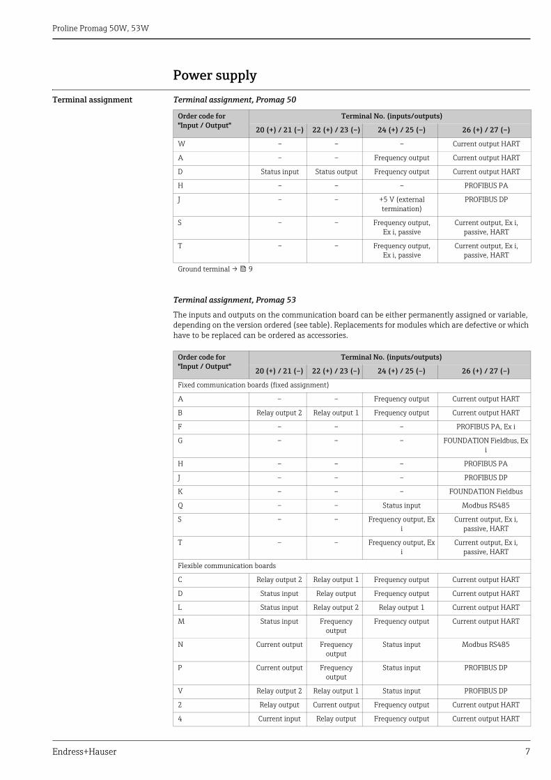
Terminal assignment Terminal assignment, Promag 50
Terminal assignment, Promag 53
The inputs and outputs on the communication board can be either permanently assigned or variable, depending on the version ordered (see table). Replacements for modules which are defective or which have to be replaced can be ordered as accessories.
Order code for"Input / Output"
Terminal No. (inputs/outputs)
20 (+) / 21 (–) 22 (+) / 23 (–) 24 (+) / 25 (–) 26 (+) / 27 (–)
W – – – Current output HART
A – – Frequency output Current output HART
D Status input Status output Frequency output Current output HART
H – – – PROFIBUS PA
J – – +5 V (external termination)
PROFIBUS DP
S – – Frequency output, Ex i, passive
Current output, Ex i, passive, HART
T – – Frequency output, Ex i, passive
Current output, Ex i, passive, HART
Ground terminal → 9
Order code for"Input / Output"
Terminal No. (inputs/outputs)
20 (+) / 21 (–) 22 (+) / 23 (–) 24 (+) / 25 (–) 26 (+) / 27 (–)
Fixed communication boards (fixed assignment)
A – – Frequency output Current output HART
B Relay output 2 Relay output 1 Frequency output Current output HART
F – – – PROFIBUS PA, Ex i
G – – – FOUNDATION Fieldbus, Ex i
H – – – PROFIBUS PA
J – – – PROFIBUS DP
K – – – FOUNDATION Fieldbus
Q – – Status input Modbus RS485
S – – Frequency output, Ex i
Current output, Ex i, passive, HART
T – – Frequency output, Ex i
Current output, Ex i, passive, HART
Flexible communication boards
C Relay output 2 Relay output 1 Frequency output Current output HART
D Status input Relay output Frequency output Current output HART
L Status input Relay output 2 Relay output 1 Current output HART
M Status input Frequency output
Frequency output Current output HART
N Current output Frequency output
Status input Modbus RS485
P Current output Frequency output
Status input PROFIBUS DP
V Relay output 2 Relay output 1 Status input PROFIBUS DP
2 Relay output Current output Frequency output Current output HART
4 Current input Relay output Frequency output Current output HART
Proline Promag 50W, 53W
8 Endress+Hauser
Supply voltage • 85 to 260 V AC, 45 to 65 Hz• 20 to 55 V AC, 45 to 65 Hz• 16 to 62 V DC
PROFIBUS PA and FOUNDATION Fieldbus• Non-Ex: 9 to 32 V DC• Ex i: 9 to 24 V DC• Ex d: 9 to 32 V DC
Power consumption • AC: < 15 VA (incl. sensor)• DC: < 15 W (incl. sensor)
Switch-on current:• Max. 3 A (< 5 ms) for 260 V AC• Max. 13.5 A (< 50 ms) for 24 V DC
Power supply failure Lasting min. ½ cycle frequency: EEPROM saves measuring system data• EEPROM or T-DAT (Promag 53 only) retain the measuring system data in the event of a power
supply failure• S-DAT: exchangeable data storage chip which stores the data of the sensor (nominal diameter, serial
number, calibration factor, zero point etc.)
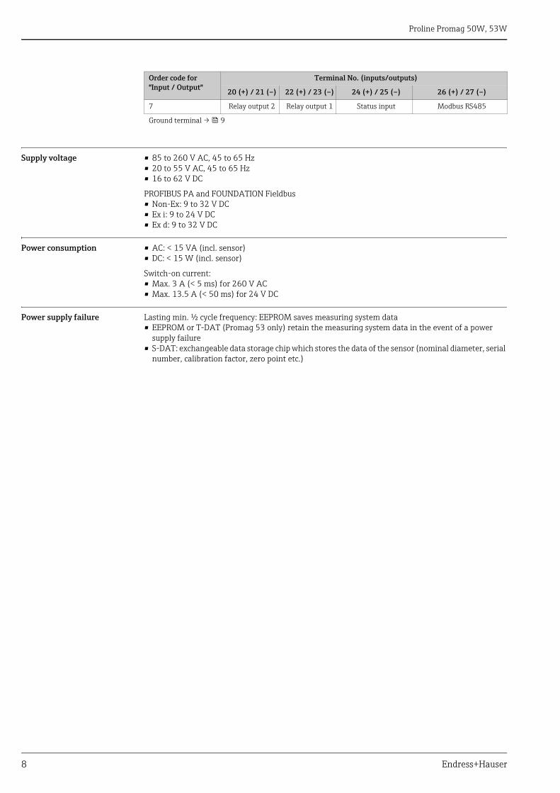
7 Relay output 2 Relay output 1 Status input Modbus RS485
Ground terminal → 9
Order code for"Input / Output"
Terminal No. (inputs/outputs)
20 (+) / 21 (–) 22 (+) / 23 (–) 24 (+) / 25 (–) 26 (+) / 27 (–)
Proline Promag 50W, 53W
Endress+Hauser 9
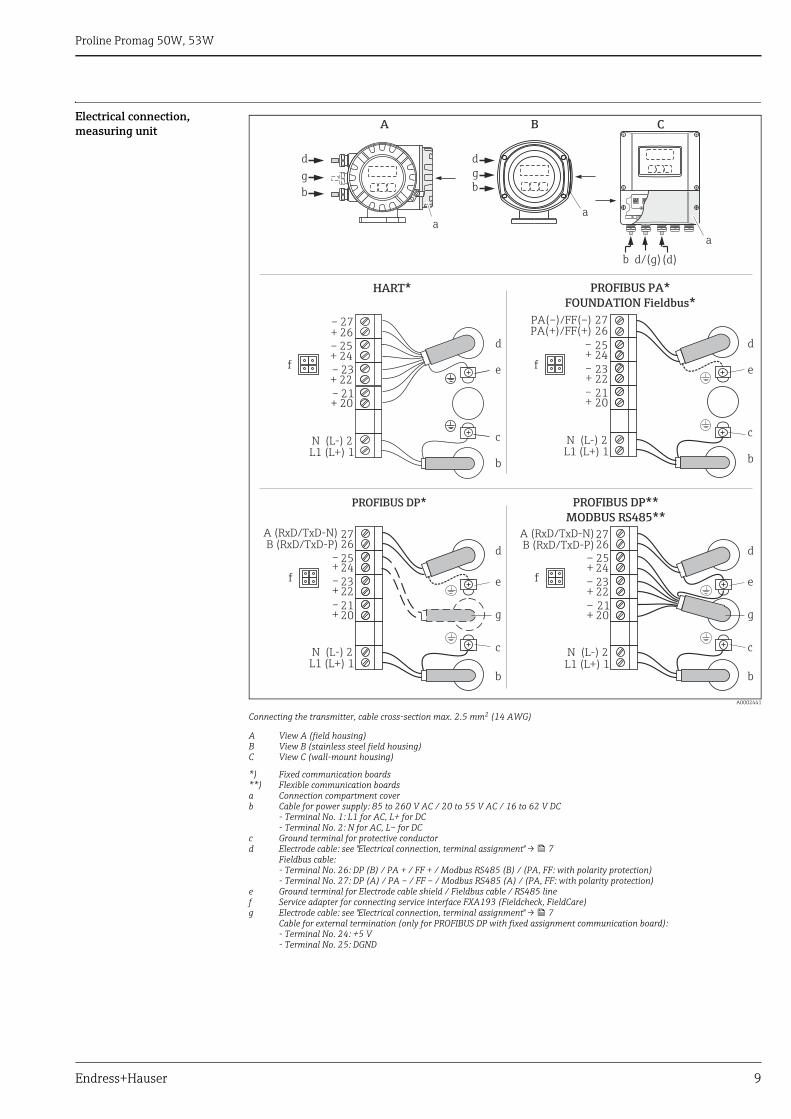
Electrical connection, measuring unit
A0002441
Connecting the transmitter, cable cross-section max. 2.5 mm2 (14 AWG)
A View A (field housing)B View B (stainless steel field housing)C View C (wall-mount housing)
*) Fixed communication boards **) Flexible communication boards a Connection compartment coverb Cable for power supply: 85 to 260 V AC / 20 to 55 V AC / 16 to 62 V DC
- Terminal No. 1: L1 for AC, L+ for DC- Terminal No. 2: N for AC, L– for DC
c Ground terminal for protective conductord Electrode cable: see "Electrical connection, terminal assignment" → 7
Fieldbus cable:- Terminal No. 26: DP (B) / PA + / FF + / Modbus RS485 (B) / (PA, FF: with polarity protection)- Terminal No. 27: DP (A) / PA – / FF – / Modbus RS485 (A) / (PA, FF: with polarity protection)
e Ground terminal for Electrode cable shield / Fieldbus cable / RS485 linef Service adapter for connecting service interface FXA193 (Fieldcheck, FieldCare)g Electrode cable: see "Electrical connection, terminal assignment" → 7
Cable for external termination (only for PROFIBUS DP with fixed assignment communication board):- Terminal No. 24: +5 V- Terminal No. 25: DGND
HART*
PROFIBUS DP**
MODBUS RS485**
L1 (L+) 1N (L-) 2
2524
–+
2322
–+
2120
–+
PROFIBUS PA*
FOUNDATION Fieldbus*
2726
L1 (L+) 1N (L-) 2
2524
–+
2322
–+
2120
–+
A (RxD/TxD-N)B (RxD/TxD-P)
2726
PA(–)/FF(–)PA(+)/FF(+)
L1 (L+) 1N (L-) 2
25–24+2322
–+
2120
–+
2726
A (RxD/TxD-N)B (RxD/TxD-P)
d
c
e
b
d
c
e
b
g
d
c
e
b
g
PROFIBUS DP*
d
c
e
b
– 27+ 26– 25+ 24– 23+ 22– 21+ 20
N (L-) 2
f f
f f
aa
d
b
a
A B C
gd
b
g
(d)b d/(g)
L1 (L+) 1
Proline Promag 50W, 53W
10 Endress+Hauser
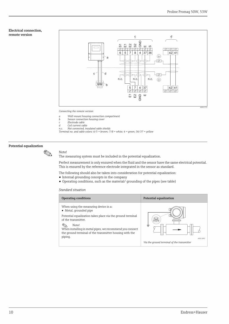
Electrical connection, remote version
A0011722
Connecting the remote version
a Wall-mount housing connection compartmentb Sensor connection housing coverc Electrode cabled Coil current cablen.c. Not connected, insulated cable shieldsTerminal no. and cable colors: 6/5 = brown; 7/8 = white; 4 = green; 36/37 = yellow
Potential equalization
! Note! The measuring system must be included in the potential equalization.
Perfect measurement is only ensured when the fluid and the sensor have the same electrical potential. This is ensured by the reference electrode integrated in the sensor as standard.
The following should also be taken into consideration for potential equalization:• Internal grounding concepts in the company• Operating conditions, such as the material/ grounding of the pipes (see table)
Standard situation
E1
E2
GN
D E
S1
E1
E2
S2
GN
D
E S
5 7 4 37 42 41
42 416 5 7 8 4 37 36
n.c. n.c.
dc
c d
a
b
n.c.
Operating conditions Potential equalization
When using the measuring device in a:• Metal, grounded pipe
Potential equalization takes place via the ground terminal of the transmitter.
! Note! When installing in metal pipes, we recommend you connect the ground terminal of the transmitter housing with the piping.
A0011892
Via the ground terminal of the transmitter
Proline Promag 50W, 53W
Endress+Hauser 11
Special situations
Cable entries Power supply and electrode cables (inputs/ outputs):• Cable entry M20 × 1.5 (8 to 12 mm / 0.31 to 0.47")• Sensor cable entry for armoured cables M20 × 1.5 (9.5 to 16 mm / 0.37 to 0.63")• Thread for cable entries, ½" NPT, G ½"
Connecting cable for remote version:• Cable entry M20 × 1.5 (8 to 12 mm / 0.31 to 0.47")• Sensor cable entry for armoured cables M20 × 1.5 (9.5 to 16 mm / 0.37 to 0.63")• Thread for cable entries, ½" NPT, G ½"
Operating conditions Potential equalization
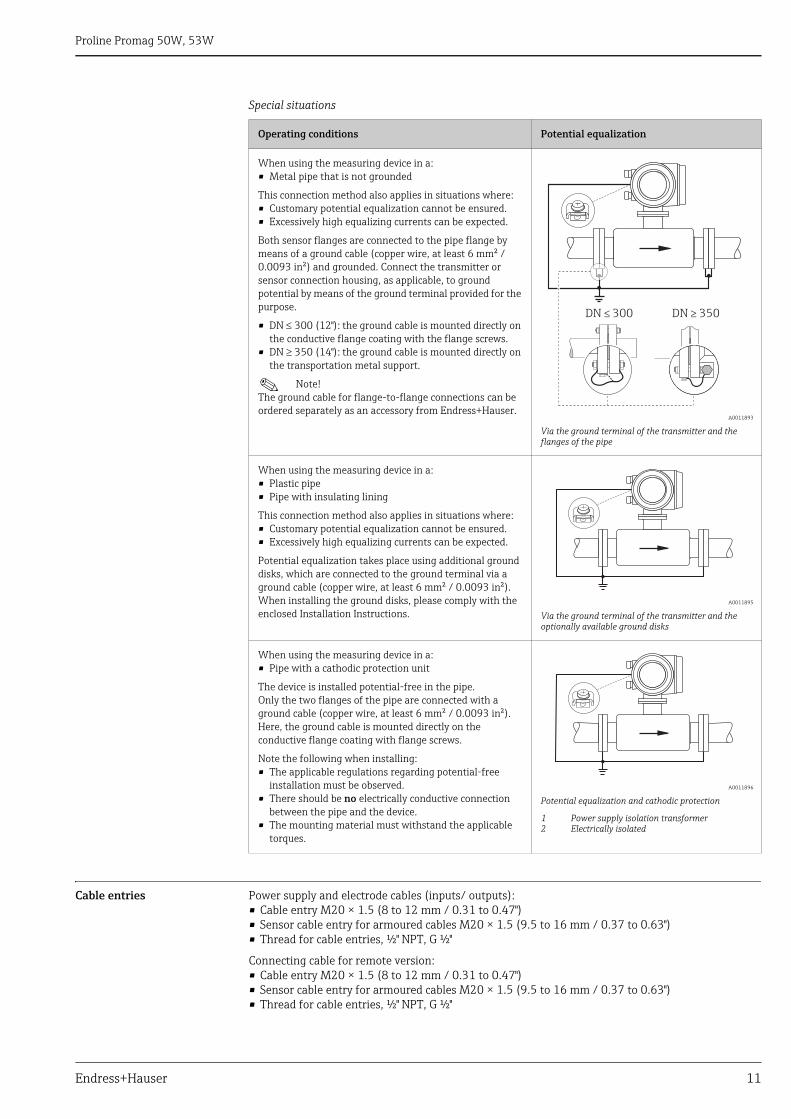
When using the measuring device in a:• Metal pipe that is not grounded
This connection method also applies in situations where:• Customary potential equalization cannot be ensured.• Excessively high equalizing currents can be expected.
Both sensor flanges are connected to the pipe flange by means of a ground cable (copper wire, at least 6 mm² / 0.0093 in²) and grounded. Connect the transmitter or sensor connection housing, as applicable, to ground potential by means of the ground terminal provided for the purpose.
• DN 300 (12"): the ground cable is mounted directly on the conductive flange coating with the flange screws.
• DN 350 (14"): the ground cable is mounted directly on the transportation metal support.
! Note! The ground cable for flange-to-flange connections can be ordered separately as an accessory from Endress+Hauser.
A0011893
Via the ground terminal of the transmitter and the flanges of the pipe
When using the measuring device in a:• Plastic pipe• Pipe with insulating lining
This connection method also applies in situations where:• Customary potential equalization cannot be ensured.• Excessively high equalizing currents can be expected.
Potential equalization takes place using additional ground disks, which are connected to the ground terminal via a ground cable (copper wire, at least 6 mm² / 0.0093 in²). When installing the ground disks, please comply with the enclosed Installation Instructions.
A0011895
Via the ground terminal of the transmitter and the optionally available ground disks
When using the measuring device in a:• Pipe with a cathodic protection unit
The device is installed potential-free in the pipe.Only the two flanges of the pipe are connected with a ground cable (copper wire, at least 6 mm² / 0.0093 in²). Here, the ground cable is mounted directly on the conductive flange coating with flange screws.
Note the following when installing:• The applicable regulations regarding potential-free
installation must be observed.• There should be no electrically conductive connection
between the pipe and the device.• The mounting material must withstand the applicable
torques.
A0011896
Potential equalization and cathodic protection
1 Power supply isolation transformer2 Electrically isolated
DN 300� DN 350�
Proline Promag 50W, 53W
12 Endress+Hauser
Remote version cable specifications
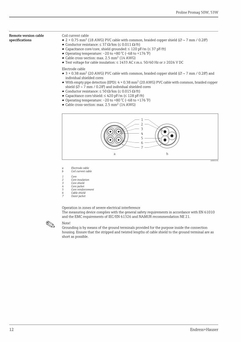
Coil current cable• 2 × 0.75 mm2 (18 AWG) PVC cable with common, braided copper shield ( 7 mm / 0.28")• Conductor resistance: 37 /km (0.011 /ft)• Capacitance core/core, shield grounded: 120 pF/m (37 pF/ft)• Operating temperature: –20 to +80 °C (–68 to +176 °F)• Cable cross-section: max. 2.5 mm2 (14 AWG)• Test voltage for cable insulation: 1433 AC r.m.s. 50/60 Hz or 2026 V DC
Electrode cable• 3 × 0.38 mm2 (20 AWG) PVC cable with common, braided copper shield ( 7 mm / 0.28") and
individual shielded cores• With empty pipe detection (EPD): 4 × 0.38 mm2 (20 AWG) PVC cable with common, braided copper
shield ( 7 mm / 0.28") and individual shielded cores• Conductor resistance: 50 /km (0.015 /ft)• Capacitance core/shield: 420 pF/m (128 pF/ft)• Operating temperature: –20 to +80 °C (–68 to +176 °F)• Cable cross-section: max. 2.5 mm2 (14 AWG)
A0003194
a Electrode cableb Coil current cable
1 Core2 Core insulation3 Core shield4 Core jacket5 Core reinforcement6 Cable shield7 Outer jacket
Operation in zones of severe electrical interferenceThe measuring device complies with the general safety requirements in accordance with EN 61010 and the EMC requirements of IEC/EN 61326 and NAMUR recommendation NE 21.
! Note! Grounding is by means of the ground terminals provided for the purpose inside the connection housing. Ensure that the stripped and twisted lengths of cable shield to the ground terminal are as short as possible.
1
2
3
4
5
6
7
a b
Proline Promag 50W, 53W
Endress+Hauser 13
Performance characteristics
Reference operating conditions
As per DIN EN 29104 and VDI/VDE 2641:• Fluid temperature: +28 °C ± 2 K (+82 °F ± 2 K)• Ambient temperature: +22 °C ±2 K (+72 °F ± 2 K)• Warm-up period: 30 minutes
Installation conditions:• Inlet run > 10 × DN• Outlet run > 5 × DN• Sensor and transmitter grounded.• The sensor is centered in the pipe.
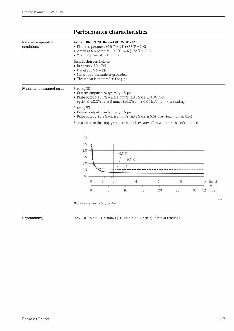
Maximum measured error Promag 50:• Current output: also typically ± 5 μA• Pulse output: ±0.5% o.r. ± 1 mm/s (±0.5% o.r. ± 0.04 in/s)
optional: ±0.2% o.r. ± 2 mm/s (±0.2% o.r. ± 0.08 in/s) (o.r. = of reading)
Promag 53:• Current output: also typically ± 5 μA• Pulse output: ±0.2% o.r. ± 2 mm/s (±0.2% o.r. ± 0.08 in/s) (o.r. = of reading)
Fluctuations in the supply voltage do not have any effect within the specified range.
A0005531
Max. measured error in % of reading
Repeatability Max. ±0.1% o.r. ± 0.5 mm/s (±0.1% o.r. ± 0.02 in/s) (o.r. = of reading)
2.5
[%]
2.0
1.5
1.0
0.5
0
0.2 %
0.5 %
0 1 2 4 6 8 10 [m/s]
v
5 10 15 20 25 30 32 [ft/s]0
Proline Promag 50W, 53W
14 Endress+Hauser
Installation
Mounting location Mounting location
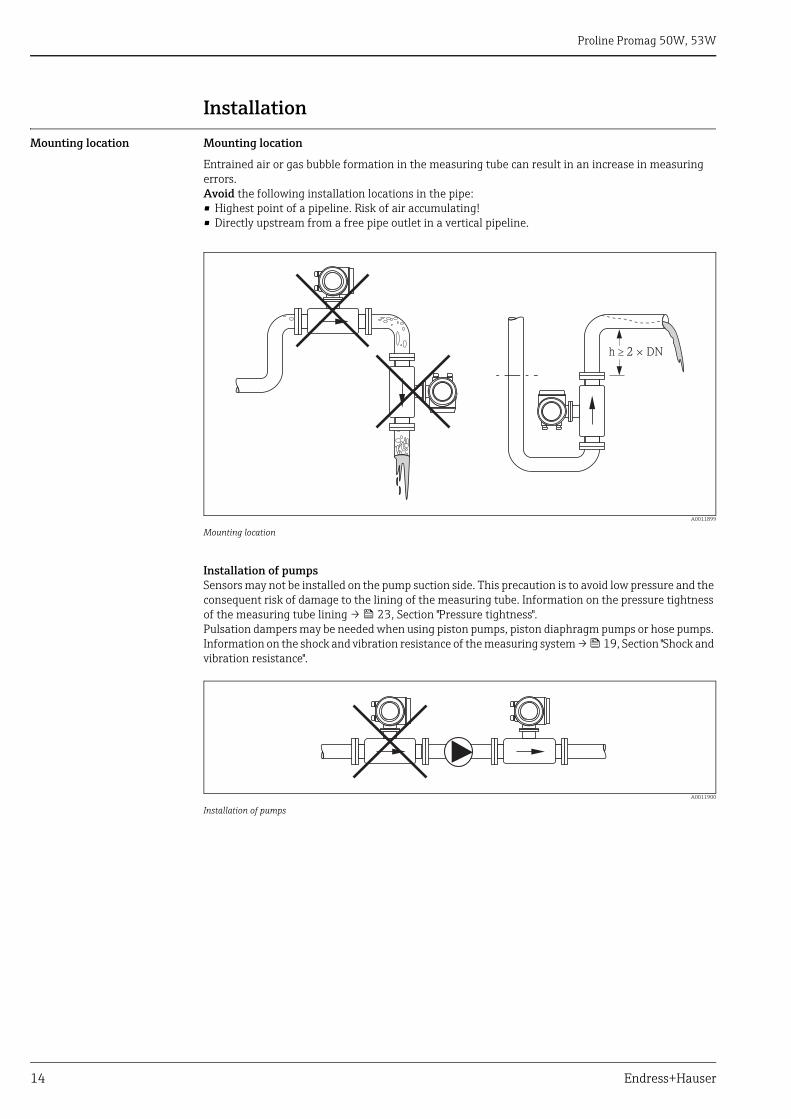
Entrained air or gas bubble formation in the measuring tube can result in an increase in measuring errors.Avoid the following installation locations in the pipe:• Highest point of a pipeline. Risk of air accumulating!• Directly upstream from a free pipe outlet in a vertical pipeline.
A0011899
Mounting location
Installation of pumpsSensors may not be installed on the pump suction side. This precaution is to avoid low pressure and the consequent risk of damage to the lining of the measuring tube. Information on the pressure tightness of the measuring tube lining → 23, Section "Pressure tightness".Pulsation dampers may be needed when using piston pumps, piston diaphragm pumps or hose pumps. Information on the shock and vibration resistance of the measuring system → 19, Section "Shock and vibration resistance".
A0011900
Installation of pumps
h 2 × DN�
Proline Promag 50W, 53W
Endress+Hauser 15
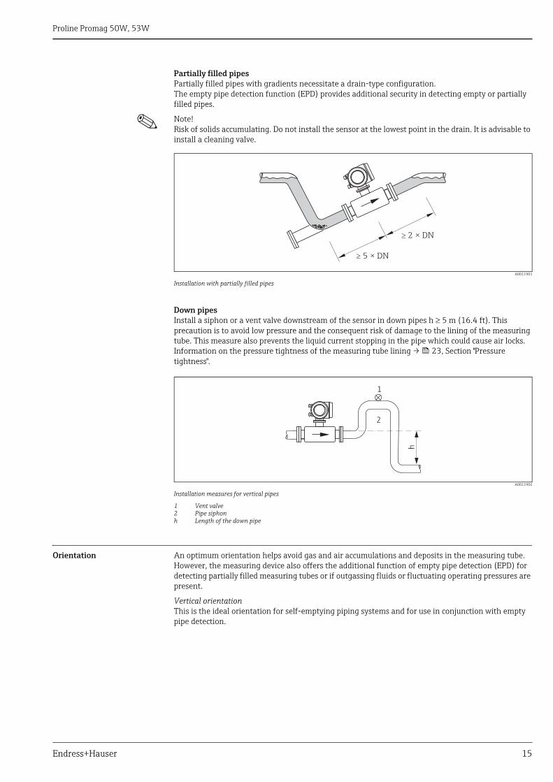
Partially filled pipesPartially filled pipes with gradients necessitate a drain-type configuration.The empty pipe detection function (EPD) provides additional security in detecting empty or partially filled pipes.
! Note! Risk of solids accumulating. Do not install the sensor at the lowest point in the drain. It is advisable to install a cleaning valve.
A0011901
Installation with partially filled pipes
Down pipesInstall a siphon or a vent valve downstream of the sensor in down pipes h 5 m (16.4 ft). This precaution is to avoid low pressure and the consequent risk of damage to the lining of the measuring tube. This measure also prevents the liquid current stopping in the pipe which could cause air locks. Information on the pressure tightness of the measuring tube lining → 23, Section "Pressure tightness".
A0011902
Installation measures for vertical pipes
1 Vent valve2 Pipe siphonh Length of the down pipe
Orientation An optimum orientation helps avoid gas and air accumulations and deposits in the measuring tube. However, the measuring device also offers the additional function of empty pipe detection (EPD) for detecting partially filled measuring tubes or if outgassing fluids or fluctuating operating pressures are present.
Vertical orientationThis is the ideal orientation for self-emptying piping systems and for use in conjunction with empty pipe detection.
� 5 DN×
� 2 DN×
h2
1
Proline Promag 50W, 53W
16 Endress+Hauser
A0011903
Vertical orientation
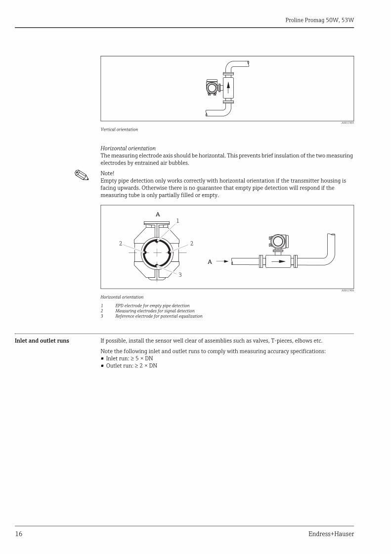
Horizontal orientationThe measuring electrode axis should be horizontal. This prevents brief insulation of the two measuring electrodes by entrained air bubbles.
! Note! Empty pipe detection only works correctly with horizontal orientation if the transmitter housing is facing upwards. Otherwise there is no guarantee that empty pipe detection will respond if the measuring tube is only partially filled or empty.
A0011904
Horizontal orientation
1 EPD electrode for empty pipe detection2 Measuring electrodes for signal detection 3 Reference electrode for potential equalization
Inlet and outlet runs If possible, install the sensor well clear of assemblies such as valves, T-pieces, elbows etc.
Note the following inlet and outlet runs to comply with measuring accuracy specifications:• Inlet run: 5 × DN• Outlet run: 2 × DN
A
1
2 2
A
3
Proline Promag 50W, 53W
Endress+Hauser 17
A0011905
Inlet and outlet run
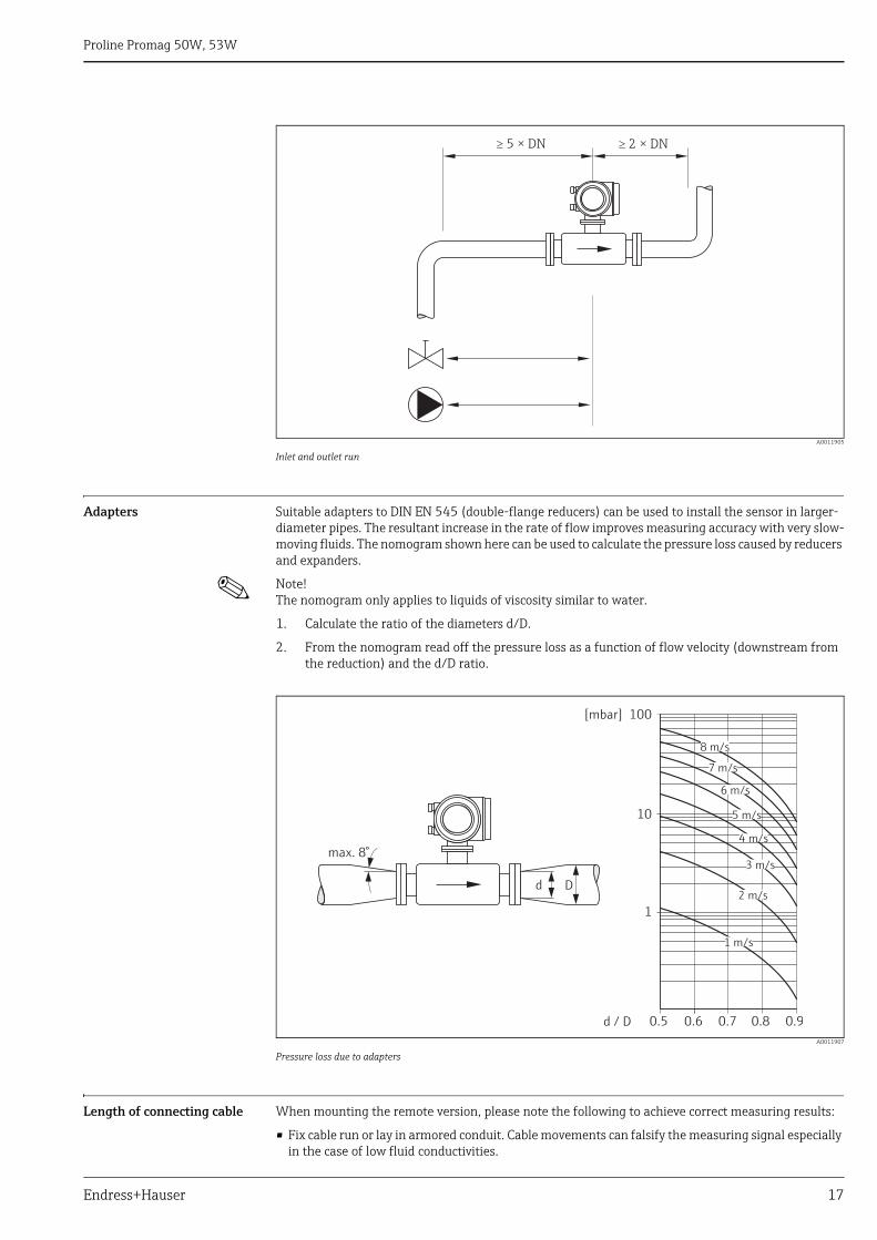
Adapters Suitable adapters to DIN EN 545 (double-flange reducers) can be used to install the sensor in larger-diameter pipes. The resultant increase in the rate of flow improves measuring accuracy with very slow-moving fluids. The nomogram shown here can be used to calculate the pressure loss caused by reducers and expanders.
! Note! The nomogram only applies to liquids of viscosity similar to water.
1. Calculate the ratio of the diameters d/D.
2. From the nomogram read off the pressure loss as a function of flow velocity (downstream from the reduction) and the d/D ratio.
A0011907
Pressure loss due to adapters
Length of connecting cable When mounting the remote version, please note the following to achieve correct measuring results:
• Fix cable run or lay in armored conduit. Cable movements can falsify the measuring signal especially in the case of low fluid conductivities.
� 5 × DN � 2 × DN
100
10
0.5d / D
[mbar]
0.6 0.7 0.8 0.9
1 m/s
2 m/s
3 m/s
4 m/s
5 m/s
6 m/s
7 m/s
8 m/s
1
Dd
max. 8°
Proline Promag 50W, 53W
18 Endress+Hauser
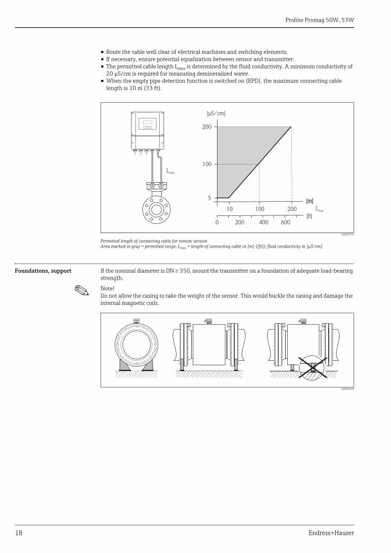
• Route the cable well clear of electrical machines and switching elements.• If necessary, ensure potential equalization between sensor and transmitter.• The permitted cable length Lmax is determined by the fluid conductivity. A minimum conductivity of
20 μS/cm is required for measuring demineralized water.• When the empty pipe detection function is switched on (EPD), the maximum connecting cable
length is 10 m (33 ft).
A0010734
Permitted length of connecting cable for remote versionArea marked in gray = permitted range; Lmax = length of connecting cable in [m] ([ft]); fluid conductivity in [μS/cm]
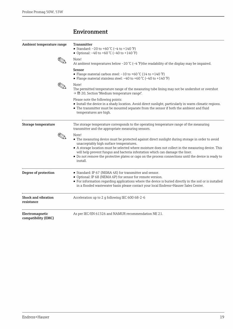
Foundations, support If the nominal diameter is DN 350, mount the transmitter on a foundation of adequate load-bearing strength.
! Note! Do not allow the casing to take the weight of the sensor. This would buckle the casing and damage the internal magnetic coils.
A0003209
200
100
5
10 100 200
Lmax
[m][m]
[µS/cm]
Lmax
[ft]200 6000 400
Proline Promag 50W, 53W
Endress+Hauser 19
Environment
Ambient temperature range Transmitter• Standard: –20 to +60 °C (–4 to +140 °F)• Optional: –40 to +60 °C (–40 to +140 °F)
! Note! At ambient temperatures below –20 °C (–4 °F)the readability of the display may be impaired.
Sensor• Flange material carbon steel: –10 to +60 °C (14 to +140 °F)• Flange material stainless steel: –40 to +60 °C (–40 to +140 °F)
! Note! The permitted temperature range of the measuring tube lining may not be undershot or overshot→ 20, Section "Medium temperature range".
Please note the following points:• Install the device in a shady location. Avoid direct sunlight, particularly in warm climatic regions.• The transmitter must be mounted separate from the sensor if both the ambient and fluid
temperatures are high.
Storage temperature The storage temperature corresponds to the operating temperature range of the measuring transmitter and the appropriate measuring sensors.
! Note! • The measuring device must be protected against direct sunlight during storage in order to avoid
unacceptably high surface temperatures.• A storage location must be selected where moisture does not collect in the measuring device. This
will help prevent fungus and bacteria infestation which can damage the liner.• Do not remove the protective plates or caps on the process connections until the device is ready to
install.
Degree of protection • Standard: IP 67 (NEMA 4X) for transmitter and sensor.• Optional: IP 68 (NEMA 6P) for sensor for remote version.• For information regarding applications where the device is buried directly in the soil or is installed
in a flooded wastewater basin please contact your local Endress+Hauser Sales Center.
Shock and vibration resistance
Acceleration up to 2 g following IEC 600 68-2-6
Electromagnetic compatibility (EMC)
As per IEC/EN 61326 and NAMUR recommendation NE 21.
Proline Promag 50W, 53W
20 Endress+Hauser
Process
Medium temperature range The permitted temperature depends on the lining of the measuring tube:• Polyurethane: –20 to +50 °C (–4 to +122 °F) (DN 25 to 1200 / 1 to 48")• Hard rubber: ±0 to +80 °C (+32 to +176 °F) (DN 50 to 2000 / 2 to 78")
Conductivity The minimum conductivity is:• 5 μS/cm for fluids generally• 20 μS/cm for demineralized water
! Note! In the remote version, the necessary minimum conductivity also depends on the cable length(→ 17, Section "Length of connecting cable").
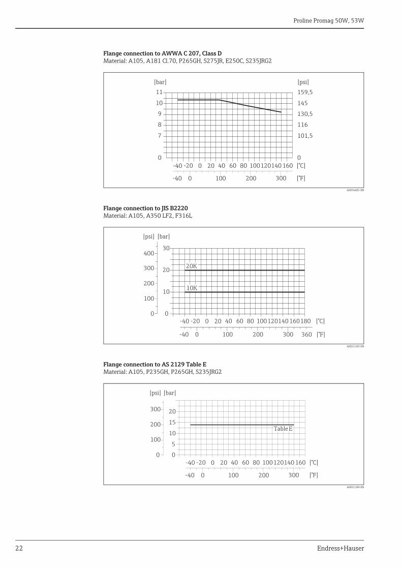
Pressure-temperature ratings
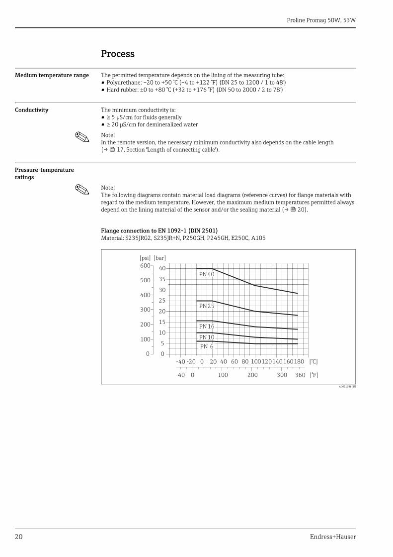
! Note! The following diagrams contain material load diagrams (reference curves) for flange materials with regard to the medium temperature. However, the maximum medium temperatures permitted always depend on the lining material of the sensor and/or the sealing material (→ 20).
Flange connection to EN 1092-1 (DIN 2501)Material: S235JRG2, S235JR+N, P250GH, P245GH, E250C, A105
A0021188-EN
0
5
10
15
20
25
35
30
40
[bar][psi]
-40 -20 0 20 40 60 80 100120140160180 [°C]
360 [°F]0-40 100 200 300
200
100
400
300
500
600
0
PN25
PN16
PN10
PN 6
PN40
Proline Promag 50W, 53W
Endress+Hauser 21
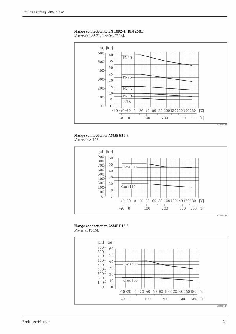
Flange connection to EN 1092-1 (DIN 2501)Material: 1.4571, 1.4404, F316L
A0021184-EN
Flange connection to ASME B16.5Material: A 105
A0021182-EN
Flange connection to ASME B16.5Material: F316L
A0021185-EN
PN16
PN10
PN40
PN 6
0
5
10
15
20
25
35
30
40
[bar][psi]
-60 -40 -20 0 20 40 60 80 100120140 160180 [°C]
360 [°F]0-40 100 200 300
200
100
400
300
500
600
0
PN25
Class300
Class150
0
10
20
30
40
50
[bar][psi]
-40 -20 0 20 40 60 80 100120140 160180 [°C]
360 [°F]0-40 100 200 300
200100
400300
500600700800900 60
0
Class300
Class150
0
10
20
30
40
50
[bar][psi]
-40 -20 0 20 40 60 80 100120140 160180 [°C]
360 [°F]0-40 100 200 300
200100
400300
500600700800900
0
60
Proline Promag 50W, 53W
22 Endress+Hauser
Flange connection to AWWA C 207, Class DMaterial: A105, A181 Cl.70, P265GH, S275JR, E250C, S235JRG2
A0034681-EN
Flange connection to JIS B2220Material: A105, A350 LF2, F316L
A0021183-EN
Flange connection to AS 2129 Table EMaterial: A105, P235GH, P265GH, S235JRG2
A0021189-EN
0
7
8
9
10
11
[bar]
0
101,5
116
130,5
145
159,5
[psi]
-40 -20 0 20 40 60 80 100120140 160 [°C]
0-40 100 200 300 [°F]
10K
20K
-40 -20 0 20 40 60 80 100120140 160180 [°C]0
10
20
30
[bar]
360 [°F]0-40 100 200 300
[psi]
200
100
400
300
0
-40 -20 0 20 40 60 80 100120140 160 [°C]0
10
5
20
15
[bar]
0-40 100 200 300 [°F]
[psi]
200
100
300
0
TableE
Proline Promag 50W, 53W
Endress+Hauser 23
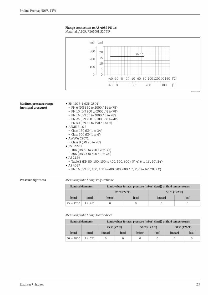
Flange connection to AS 4087 PN 16Material: A105, P265GH, S275JR
A0023077-EN
Medium pressure range (nominal pressure)
• EN 1092-1 (DIN 2501)– PN 6 (DN 350 to 2000 / 14 to 78")– PN 10 (DN 200 to 2000 / 8 to 78")– PN 16 (DN 65 to 2000 / 3 to 78")– PN 25 (DN 200 to 1000 / 8 to 40")– PN 40 (DN 25 to 150 / 1 to 6")
• ASME B 16.5– Class 150 (DN 1 to 24")– Class 300 (DN 1 to 6")
• AWWA C2072– Class D (DN 28 to 78")
• JIS B2220– 10K (DN 50 to 750 / 2 to 30")– 20K (DN 25 to 600 / 1 to 24")
• AS 2129– Table E (DN 80, 100, 150 to 400, 500, 600 / 3", 4", 6 to 16", 20", 24")
• AS 4087– PN 16 (DN 80, 100, 150 to 400, 500, 600 / 3", 4", 6 to 16", 20", 24")
Pressure tightness Measuring tube lining: Polyurethane
Measuring tube lining: Hard rubber
-40 -20 0 20 40 60 80 100120140 160 [°C]0
10
5
20
15
[bar]
0-40 100 200 300 [°F]
[psi]
200
100
300
0
PN16
Nominal diameter Limit values for abs. pressure [mbar] ([psi]) at fluid temperatures:
25 °C (77 °F) 50 °C (122 °F)
[mm] [inch] [mbar] [psi] [mbar] [psi]
25 to 1200 1 to 48" 0 0 0 0
Nominal diameter Limit values for abs. pressure [mbar] ([psi]) at fluid temperatures:
25 °C (77 °F) 50 °C (122 °F) 80 °C (176 °F)
[mm] [inch] [mbar] [psi] [mbar] [psi] [mbar] [psi]
50 to 2000 2 to 78" 0 0 0 0 0 0
Proline Promag 50W, 53W
24 Endress+Hauser
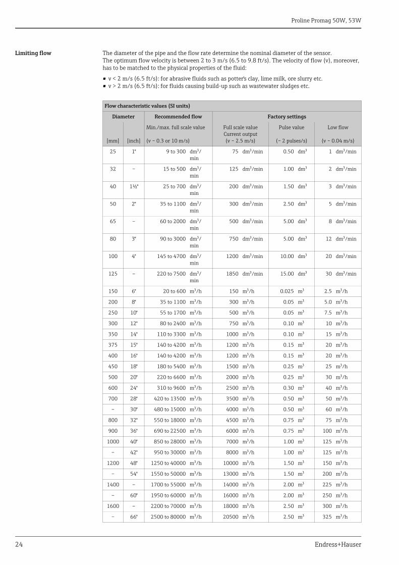
Limiting flow The diameter of the pipe and the flow rate determine the nominal diameter of the sensor.The optimum flow velocity is between 2 to 3 m/s (6.5 to 9.8 ft/s). The velocity of flow (v), moreover, has to be matched to the physical properties of the fluid:
• v < 2 m/s (6.5 ft/s): for abrasive fluids such as potter's clay, lime milk, ore slurry etc.• v > 2 m/s (6.5 ft/s): for fluids causing build-up such as wastewater sludges etc.
Flow characteristic values (SI units)
Diameter Recommended flow Factory settings
[mm] [inch]
Min./max. full scale value (v ~ 0.3 or 10 m/s)
Full scale valueCurrent output(v ~ 2.5 m/s)
Pulse value
(~ 2 pulses/s)
Low flow
(v ~ 0.04 m/s)
25 1" 9 to 300 dm/min
75 dm/min 0.50 dm 1 dm/min
32 – 15 to 500 dm/min
125 dm/min 1.00 dm 2 dm/min
40 1½" 25 to 700 dm/min
200 dm/min 1.50 dm 3 dm/min
50 2" 35 to 1100 dm/min
300 dm/min 2.50 dm 5 dm/min
65 – 60 to 2000 dm/min
500 dm/min 5.00 dm 8 dm/min
80 3" 90 to 3000 dm/min
750 dm/min 5.00 dm 12 dm/min
100 4" 145 to 4700 dm/min
1200 dm/min 10.00 dm 20 dm/min
125 – 220 to 7500 dm/min
1850 dm/min 15.00 dm 30 dm/min
150 6" 20 to 600 m/h 150 m/h 0.025 m 2.5 m/h
200 8" 35 to 1100 m/h 300 m/h 0.05 m 5.0 m/h
250 10" 55 to 1700 m/h 500 m/h 0.05 m 7.5 m/h
300 12" 80 to 2400 m/h 750 m/h 0.10 m 10 m/h
350 14" 110 to 3300 m/h 1000 m/h 0.10 m 15 m/h
375 15" 140 to 4200 m/h 1200 m/h 0.15 m 20 m/h
400 16" 140 to 4200 m/h 1200 m/h 0.15 m 20 m/h
450 18" 180 to 5400 m/h 1500 m/h 0.25 m 25 m/h
500 20" 220 to 6600 m/h 2000 m/h 0.25 m 30 m/h
600 24" 310 to 9600 m/h 2500 m/h 0.30 m 40 m/h
700 28" 420 to 13500 m/h 3500 m/h 0.50 m 50 m/h
– 30" 480 to 15000 m/h 4000 m/h 0.50 m 60 m/h
800 32" 550 to 18000 m/h 4500 m/h 0.75 m 75 m/h
900 36" 690 to 22500 m/h 6000 m/h 0.75 m 100 m/h
1000 40" 850 to 28000 m/h 7000 m/h 1.00 m 125 m/h
– 42" 950 to 30000 m/h 8000 m/h 1.00 m 125 m/h
1200 48" 1250 to 40000 m/h 10000 m/h 1.50 m 150 m/h
– 54" 1550 to 50000 m/h 13000 m/h 1.50 m 200 m/h
1400 – 1700 to 55000 m/h 14000 m/h 2.00 m 225 m/h
– 60" 1950 to 60000 m/h 16000 m/h 2.00 m 250 m/h
1600 – 2200 to 70000 m/h 18000 m/h 2.50 m 300 m/h
– 66" 2500 to 80000 m/h 20500 m/h 2.50 m 325 m/h
Proline Promag 50W, 53W
Endress+Hauser 25
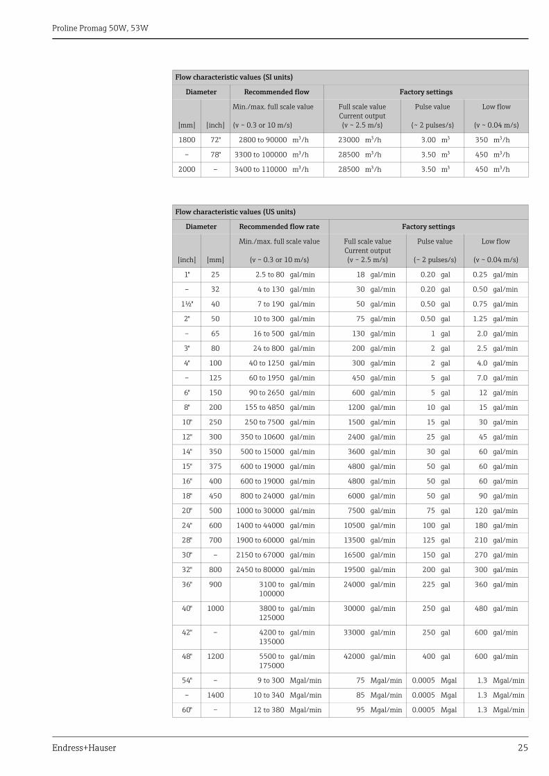
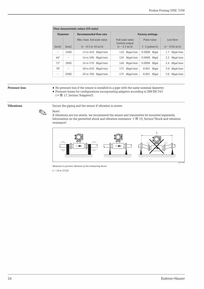
1800 72" 2800 to 90000 m/h 23000 m/h 3.00 m 350 m/h
– 78" 3300 to 100000 m/h 28500 m/h 3.50 m 450 m/h
2000 – 3400 to 110000 m/h 28500 m/h 3.50 m 450 m/h
Flow characteristic values (US units)
Diameter Recommended flow rate Factory settings
[inch] [mm]
Min./max. full scale value
(v ~ 0.3 or 10 m/s)
Full scale valueCurrent output(v ~ 2.5 m/s)
Pulse value
(~ 2 pulses/s)
Low flow
(v ~ 0.04 m/s)
1" 25 2.5 to 80 gal/min 18 gal/min 0.20 gal 0.25 gal/min
– 32 4 to 130 gal/min 30 gal/min 0.20 gal 0.50 gal/min
1½" 40 7 to 190 gal/min 50 gal/min 0.50 gal 0.75 gal/min
2" 50 10 to 300 gal/min 75 gal/min 0.50 gal 1.25 gal/min
– 65 16 to 500 gal/min 130 gal/min 1 gal 2.0 gal/min
3" 80 24 to 800 gal/min 200 gal/min 2 gal 2.5 gal/min
4" 100 40 to 1250 gal/min 300 gal/min 2 gal 4.0 gal/min
– 125 60 to 1950 gal/min 450 gal/min 5 gal 7.0 gal/min
6" 150 90 to 2650 gal/min 600 gal/min 5 gal 12 gal/min
8" 200 155 to 4850 gal/min 1200 gal/min 10 gal 15 gal/min
10" 250 250 to 7500 gal/min 1500 gal/min 15 gal 30 gal/min
12" 300 350 to 10600 gal/min 2400 gal/min 25 gal 45 gal/min
14" 350 500 to 15000 gal/min 3600 gal/min 30 gal 60 gal/min
15" 375 600 to 19000 gal/min 4800 gal/min 50 gal 60 gal/min
16" 400 600 to 19000 gal/min 4800 gal/min 50 gal 60 gal/min
18" 450 800 to 24000 gal/min 6000 gal/min 50 gal 90 gal/min
20" 500 1000 to 30000 gal/min 7500 gal/min 75 gal 120 gal/min
24" 600 1400 to 44000 gal/min 10500 gal/min 100 gal 180 gal/min
28" 700 1900 to 60000 gal/min 13500 gal/min 125 gal 210 gal/min
30" – 2150 to 67000 gal/min 16500 gal/min 150 gal 270 gal/min
32" 800 2450 to 80000 gal/min 19500 gal/min 200 gal 300 gal/min
36" 900 3100 to100000
gal/min 24000 gal/min 225 gal 360 gal/min
40" 1000 3800 to125000
gal/min 30000 gal/min 250 gal 480 gal/min
42" – 4200 to135000
gal/min 33000 gal/min 250 gal 600 gal/min
48" 1200 5500 to175000
gal/min 42000 gal/min 400 gal 600 gal/min
54" – 9 to 300 Mgal/min 75 Mgal/min 0.0005 Mgal 1.3 Mgal/min
– 1400 10 to 340 Mgal/min 85 Mgal/min 0.0005 Mgal 1.3 Mgal/min
60" – 12 to 380 Mgal/min 95 Mgal/min 0.0005 Mgal 1.3 Mgal/min
Flow characteristic values (SI units)
Diameter Recommended flow Factory settings
[mm] [inch]
Min./max. full scale value (v ~ 0.3 or 10 m/s)
Full scale valueCurrent output(v ~ 2.5 m/s)
Pulse value
(~ 2 pulses/s)
Low flow
(v ~ 0.04 m/s)
Proline Promag 50W, 53W
26 Endress+Hauser
Pressure loss • No pressure loss if the sensor is installed in a pipe with the same nominal diameter.• Pressure losses for configurations incorporating adapters according to DIN EN 545
(→ 17, Section "Adapters").
Vibrations Secure the piping and the sensor if vibration is severe.
! Note! If vibrations are too severe, we recommend the sensor and transmitter be mounted separately. Information on the permitted shock and vibration resistance → 19, Section "Shock and vibration resistance".
A0011906
Measures to prevent vibration of the measuring device
L > 10 m (33 ft)
– 1600 13 to 450 Mgal/min 110 Mgal/min 0.0008 Mgal 1.7 Mgal/min
66" – 14 to 500 Mgal/min 120 Mgal/min 0.0008 Mgal 2.2 Mgal/min
72" 1800 16 to 570 Mgal/min 140 Mgal/min 0.0008 Mgal 2.6 Mgal/min
78" – 18 to 650 Mgal/min 175 Mgal/min 0.001 Mgal 3.0 Mgal/min
– 2000 20 to 700 Mgal/min 175 Mgal/min 0.001 Mgal 3.0 Mgal/min
Flow characteristic values (US units)
Diameter Recommended flow rate Factory settings
[inch] [mm]
Min./max. full scale value
(v ~ 0.3 or 10 m/s)
Full scale valueCurrent output(v ~ 2.5 m/s)
Pulse value
(~ 2 pulses/s)
Low flow
(v ~ 0.04 m/s)
L
Proline Promag 50W, 53W
Endress+Hauser 27
Mechanical construction
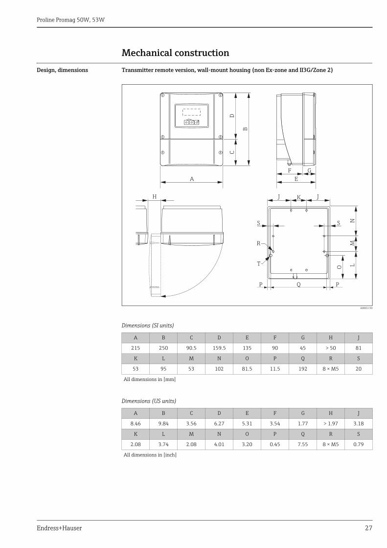
Design, dimensions Transmitter remote version, wall-mount housing (non Ex-zone and II3G/Zone 2)
A0001150
Dimensions (SI units)
Dimensions (US units)
A B C D E F G H J
215 250 90.5 159.5 135 90 45 > 50 81
K L M N O P Q R S
53 95 53 102 81.5 11.5 192 8 × M5 20
All dimensions in [mm]
A B C D E F G H J
8.46 9.84 3.56 6.27 5.31 3.54 1.77 > 1.97 3.18
K L M N O P Q R S
2.08 3.74 2.08 4.01 3.20 0.45 7.55 8 × M5 0.79
All dimensions in [inch]
EscE- +
DC
B
A
F
E
G
KJ
Q
NLO
R
H J
M
P P
SS
T
Proline Promag 50W, 53W
28 Endress+Hauser
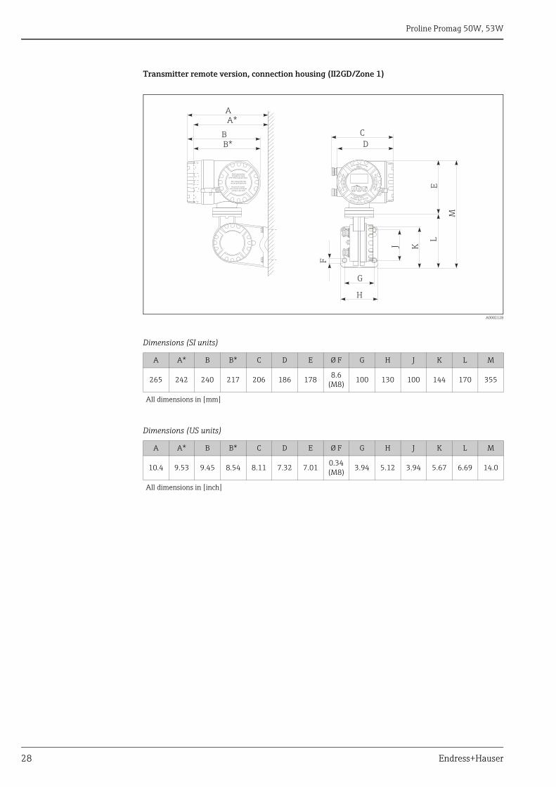
Transmitter remote version, connection housing (II2GD/Zone 1)
A0002128
Dimensions (SI units)
Dimensions (US units)
A A* B B* C D E Ø F G H J K L M
265 242 240 217 206 186 1788.6
(M8) 100 130 100 144 170 355
All dimensions in [mm]
A A* B B* C D E Ø F G H J K L M
10.4 9.53 9.45 8.54 8.11 7.32 7.010.34 (M8) 3.94 5.12 3.94 5.67 6.69 14.0
All dimensions in [inch]
Esc
E- +
Nicht unter S pannungöffnen
Ke
ep
co
ve
rtig
ht
wh
ilecirc u
it sa
rea
live
Nepasouvrirl’appareil soustension
Ke
ep
co
ver
tig
ht
wh
ileci
rcu
its
are
aliv
e
Nicht-eigensichereStromkreise durch
IP40-Abdeckung geschützt
Non-intrinsically safecircuits Ip40 protected
Boucles de courantsans sécurité intrinsèque
protégées par Ip40
B*B
A*A
F
G
D
C
H
J K
L
M
E
Proline Promag 50W, 53W
Endress+Hauser 29
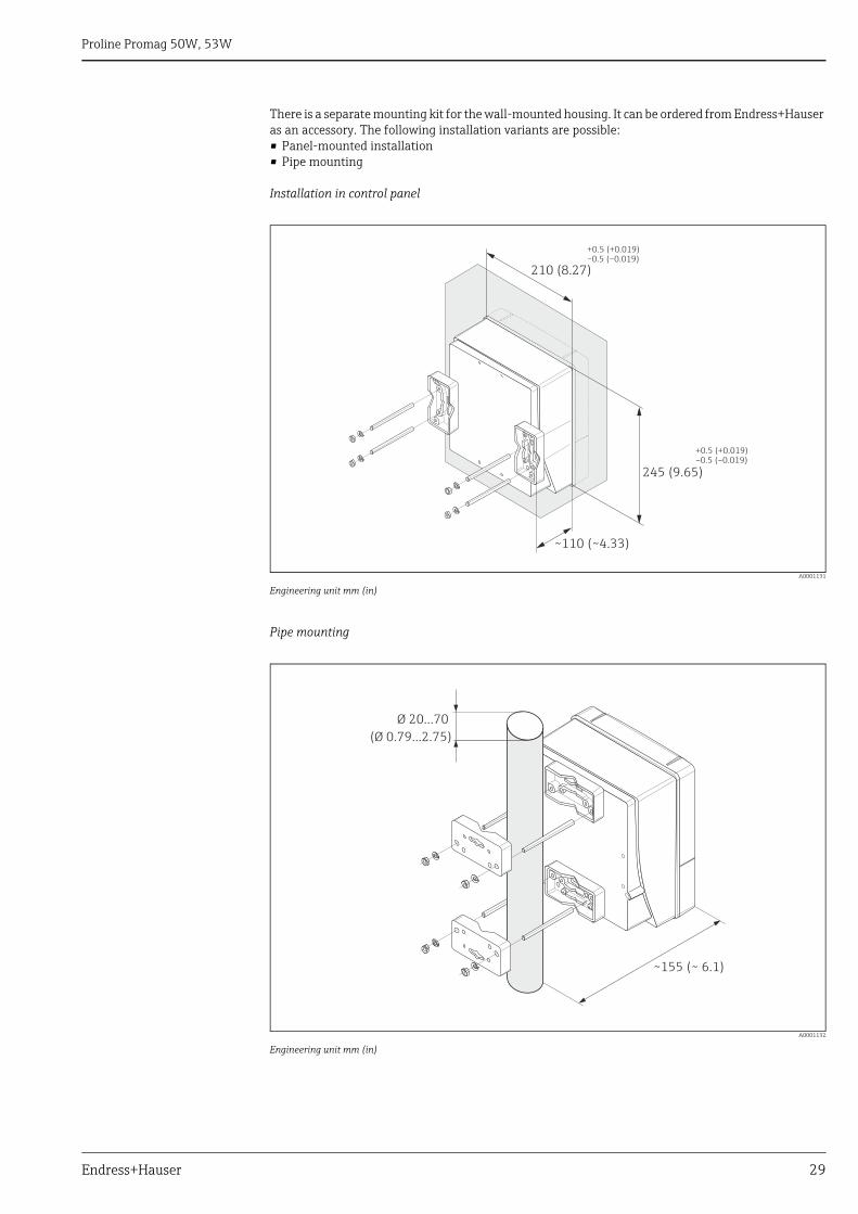
There is a separate mounting kit for the wall-mounted housing. It can be ordered from Endress+Hauser as an accessory. The following installation variants are possible:• Panel-mounted installation• Pipe mounting
Installation in control panel
A0001131
Engineering unit mm (in)
Pipe mounting
A0001132
Engineering unit mm (in)
245 (9.65)
~110 (~4.33)
210 (8.27)
+0.5 (+0.019)–0.5 (–0.019)
+0.5 (+0.019)–0.5 (–0.019)
Ø 20…70
(Ø 0.79…2.75)
~ ~ 6.1)155 (
Proline Promag 50W, 53W
30 Endress+Hauser
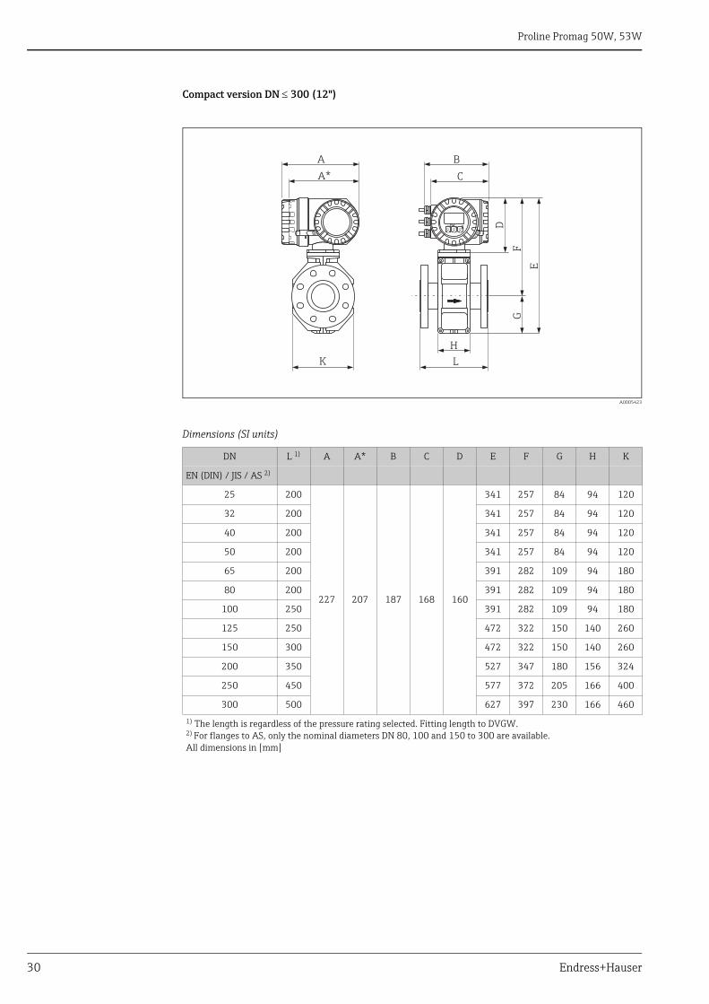
Compact version DN 300 (12")
A0005423
Dimensions (SI units)
DN L 1) A A* B C D E F G H K
EN (DIN) / JIS / AS 2)
25 200
227 207 187 168 160
341 257 84 94 120
32 200 341 257 84 94 120
40 200 341 257 84 94 120
50 200 341 257 84 94 120
65 200 391 282 109 94 180
80 200 391 282 109 94 180
100 250 391 282 109 94 180
125 250 472 322 150 140 260
150 300 472 322 150 140 260
200 350 527 347 180 156 324
250 450 577 372 205 166 400
300 500 627 397 230 166 460
1) The length is regardless of the pressure rating selected. Fitting length to DVGW.2) For flanges to AS, only the nominal diameters DN 80, 100 and 150 to 300 are available.All dimensions in [mm]
EscE- +
K
H
L
E
GF
A*
A B
C
D
Proline Promag 50W, 53W
Endress+Hauser 31
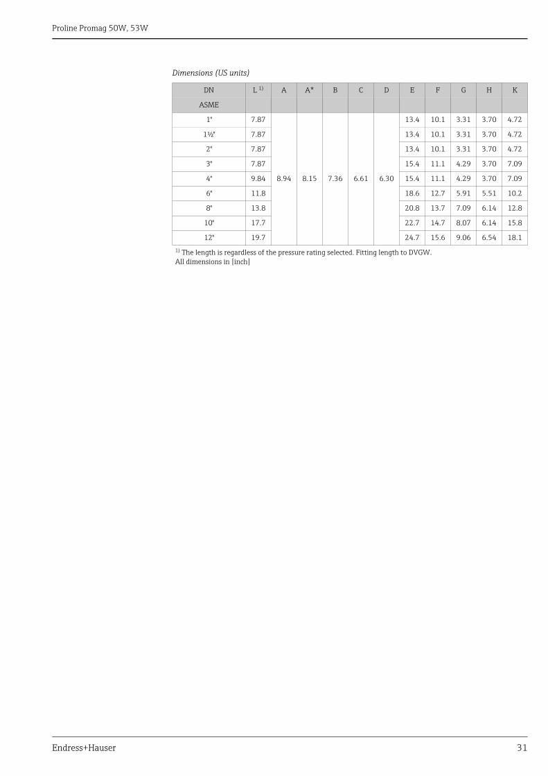
Dimensions (US units)
DN L 1) A A* B C D E F G H K
ASME
1" 7.87
8.94 8.15 7.36 6.61 6.30
13.4 10.1 3.31 3.70 4.72
1½" 7.87 13.4 10.1 3.31 3.70 4.72
2" 7.87 13.4 10.1 3.31 3.70 4.72
3" 7.87 15.4 11.1 4.29 3.70 7.09
4" 9.84 15.4 11.1 4.29 3.70 7.09
6" 11.8 18.6 12.7 5.91 5.51 10.2
8" 13.8 20.8 13.7 7.09 6.14 12.8
10" 17.7 22.7 14.7 8.07 6.14 15.8
12" 19.7 24.7 15.6 9.06 6.54 18.1
1) The length is regardless of the pressure rating selected. Fitting length to DVGW.All dimensions in [inch]
Proline Promag 50W, 53W
32 Endress+Hauser
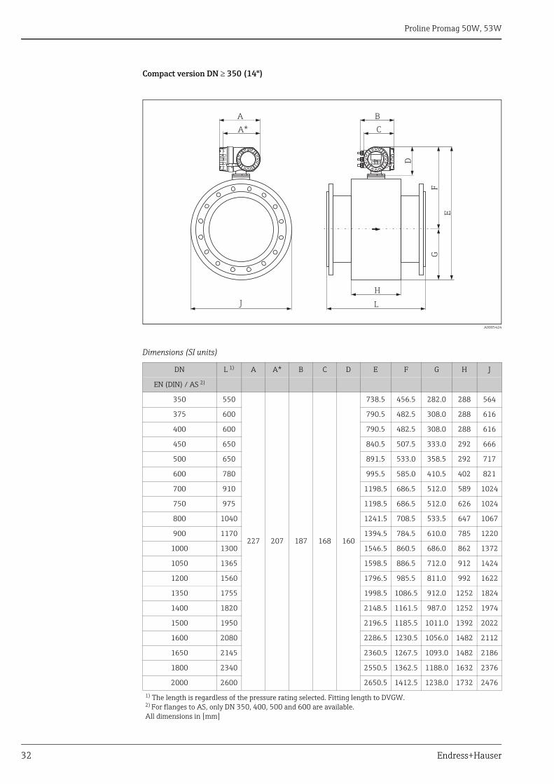
Compact version DN 350 (14")
A0005424
Dimensions (SI units)
DN L 1) A A* B C D E F G H J
EN (DIN) / AS 2)
350 550
227 207 187 168 160
738.5 456.5 282.0 288 564
375 600 790.5 482.5 308.0 288 616
400 600 790.5 482.5 308.0 288 616
450 650 840.5 507.5 333.0 292 666
500 650 891.5 533.0 358.5 292 717
600 780 995.5 585.0 410.5 402 821
700 910 1198.5 686.5 512.0 589 1024
750 975 1198.5 686.5 512.0 626 1024
800 1040 1241.5 708.5 533.5 647 1067
900 1170 1394.5 784.5 610.0 785 1220
1000 1300 1546.5 860.5 686.0 862 1372
1050 1365 1598.5 886.5 712.0 912 1424
1200 1560 1796.5 985.5 811.0 992 1622
1350 1755 1998.5 1086.5 912.0 1252 1824
1400 1820 2148.5 1161.5 987.0 1252 1974
1500 1950 2196.5 1185.5 1011.0 1392 2022
1600 2080 2286.5 1230.5 1056.0 1482 2112
1650 2145 2360.5 1267.5 1093.0 1482 2186
1800 2340 2550.5 1362.5 1188.0 1632 2376
2000 2600 2650.5 1412.5 1238.0 1732 2476
1) The length is regardless of the pressure rating selected. Fitting length to DVGW.2) For flanges to AS, only DN 350, 400, 500 and 600 are available.All dimensions in [mm]
L
H
E
GF
J
Esc E- +
A B
A* C
D
Proline Promag 50W, 53W
Endress+Hauser 33
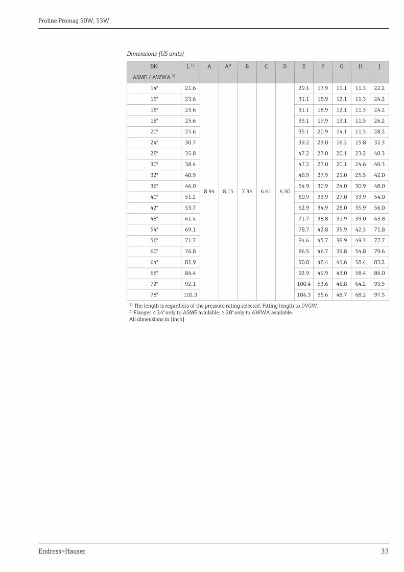
Dimensions (US units)
DN L 1) A A* B C D E F G H J
ASME / AWWA 2)
14" 21.6
8.94 8.15 7.36 6.61 6.30
29.1 17.9 11.1 11.3 22.2
15" 23.6 31.1 18.9 12.1 11.3 24.2
16" 23.6 31.1 18.9 12.1 11.3 24.2
18" 25.6 33.1 19.9 13.1 11.5 26.2
20" 25.6 35.1 20.9 14.1 11.5 28.2
24" 30.7 39.2 23.0 16.2 15.8 32.3
28" 35.8 47.2 27.0 20.1 23.2 40.3
30" 38.4 47.2 27.0 20.1 24.6 40.3
32" 40.9 48.9 27.9 21.0 25.5 42.0
36" 46.0 54.9 30.9 24.0 30.9 48.0
40" 51.2 60.9 33.9 27.0 33.9 54.0
42" 53.7 62.9 34.9 28.0 35.9 56.0
48" 61.4 71.7 38.8 31.9 39.0 63.8
54" 69.1 78.7 42.8 35.9 42.3 71.8
56" 71.7 84.6 45.7 38.9 49.3 77.7
60" 76.8 86.5 46.7 39.8 54.8 79.6
64" 81.9 90.0 48.4 41.6 58.4 83.2
66" 84.4 92.9 49.9 43.0 58.4 86.0
72" 92.1 100.4 53.6 46.8 64.2 93.5
78" 102.3 104.3 55.6 48.7 68.2 97.5
1) The length is regardless of the pressure rating selected. Fitting length to DVGW.2) Flanges 24" only to ASME available, 28" only to AWWA available.All dimensions in [inch]
Proline Promag 50W, 53W
34 Endress+Hauser
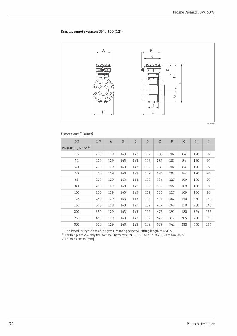
Sensor, remote version DN 300 (12")
A0012462
Dimensions (SI units)
DN L 1) A B C D E F G H J
EN (DIN) / JIS / AS 2)
25 200 129 163 143 102 286 202 84 120 94
32 200 129 163 143 102 286 202 84 120 94
40 200 129 163 143 102 286 202 84 120 94
50 200 129 163 143 102 286 202 84 120 94
65 200 129 163 143 102 336 227 109 180 94
80 200 129 163 143 102 336 227 109 180 94
100 250 129 163 143 102 336 227 109 180 94
125 250 129 163 143 102 417 267 150 260 140
150 300 129 163 143 102 417 267 150 260 140
200 350 129 163 143 102 472 292 180 324 156
250 450 129 163 143 102 522 317 205 400 166
300 500 129 163 143 102 572 342 230 460 166
1) The length is regardless of the pressure rating selected. Fitting length to DVGW.2) For flanges to AS, only the nominal diameters DN 80, 100 and 150 to 300 are available.All dimensions in [mm]
J
L
E
GF
H
B
C
A
D
Proline Promag 50W, 53W
Endress+Hauser 35
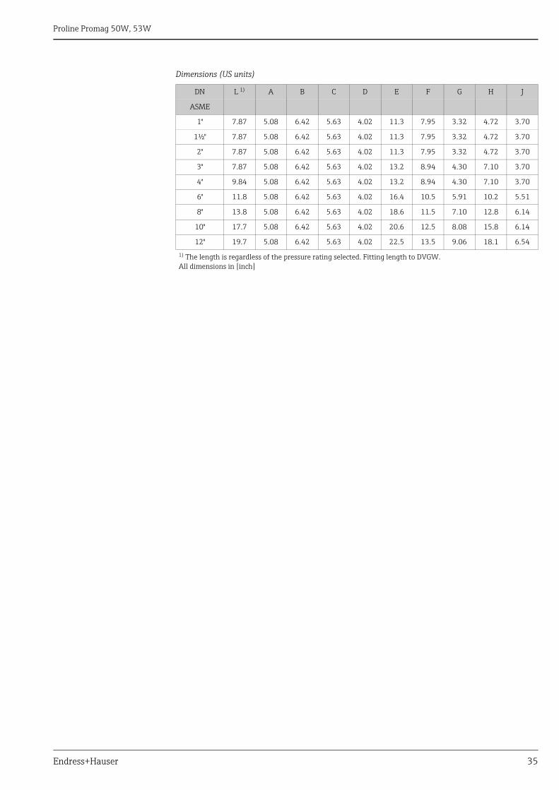
Dimensions (US units)
DN L 1) A B C D E F G H J
ASME
1" 7.87 5.08 6.42 5.63 4.02 11.3 7.95 3.32 4.72 3.70
1½" 7.87 5.08 6.42 5.63 4.02 11.3 7.95 3.32 4.72 3.70
2" 7.87 5.08 6.42 5.63 4.02 11.3 7.95 3.32 4.72 3.70
3" 7.87 5.08 6.42 5.63 4.02 13.2 8.94 4.30 7.10 3.70
4" 9.84 5.08 6.42 5.63 4.02 13.2 8.94 4.30 7.10 3.70
6" 11.8 5.08 6.42 5.63 4.02 16.4 10.5 5.91 10.2 5.51
8" 13.8 5.08 6.42 5.63 4.02 18.6 11.5 7.10 12.8 6.14
10" 17.7 5.08 6.42 5.63 4.02 20.6 12.5 8.08 15.8 6.14
12" 19.7 5.08 6.42 5.63 4.02 22.5 13.5 9.06 18.1 6.54
1) The length is regardless of the pressure rating selected. Fitting length to DVGW.All dimensions in [inch]
Proline Promag 50W, 53W
36 Endress+Hauser
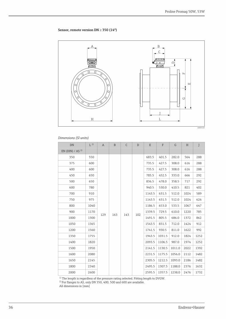
Sensor, remote version DN 350 (14")
A0003220
Dimensions (SI units)
DN L 1) A B C D E F G H J
EN (DIN) / AS 2)
350 550
129 163 143 102
683.5 401.5 282.0 564 288
375 600 735.5 427.5 308.0 616 288
400 600 735.5 427.5 308.0 616 288
450 650 785.5 452.5 333.0 666 292
500 650 836.5 478.0 358.5 717 292
600 780 940.5 530.0 410.5 821 402
700 910 1143.5 631.5 512.0 1024 589
750 975 1143.5 631.5 512.0 1024 626
800 1040 1186.5 653.0 533.5 1067 647
900 1170 1339.5 729.5 610.0 1220 785
1000 1300 1491.5 805.5 686.0 1372 862
1050 1365 1543.5 831.5 712.0 1424 912
1200 1560 1741.5 930.5 811.0 1622 992
1350 1755 1943.5 1031.5 912.0 1824 1252
1400 1820 2093.5 1106.5 987.0 1974 1252
1500 1950 2141.5 1130.5 1011.0 2022 1392
1600 2080 2231.5 1175.5 1056.0 2112 1482
1650 2145 2305.5 1212.5 1093.0 2186 1482
1800 2340 2495.5 1307.5 1188.0 2376 1632
2000 2600 2595.5 1357.5 1238.0 2476 1732
1) The length is regardless of the pressure rating selected. Fitting length to DVGW.2) For flanges to AS, only DN 350, 400, 500 and 600 are available.All dimensions in [mm]
H
E
GF
L
J
A B
C
D
Proline Promag 50W, 53W
Endress+Hauser 37
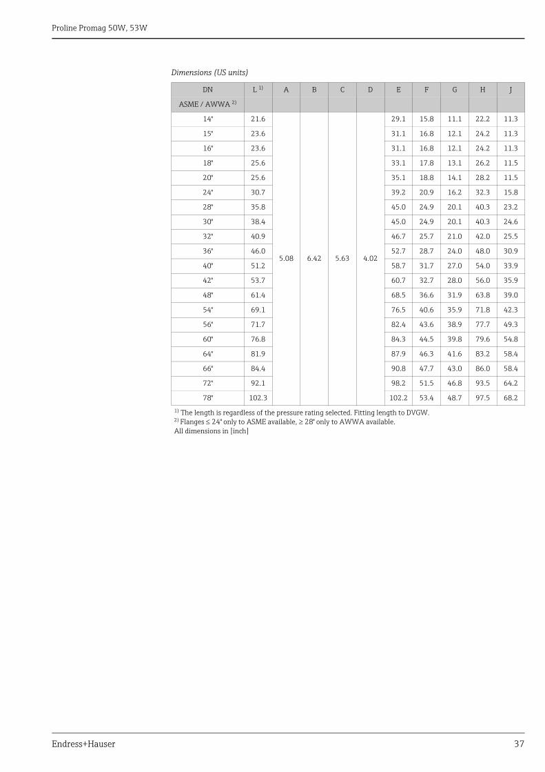
Dimensions (US units)
DN L 1) A B C D E F G H J
ASME / AWWA 2)
14" 21.6
5.08 6.42 5.63 4.02
29.1 15.8 11.1 22.2 11.3
15" 23.6 31.1 16.8 12.1 24.2 11.3
16" 23.6 31.1 16.8 12.1 24.2 11.3
18" 25.6 33.1 17.8 13.1 26.2 11.5
20" 25.6 35.1 18.8 14.1 28.2 11.5
24" 30.7 39.2 20.9 16.2 32.3 15.8
28" 35.8 45.0 24.9 20.1 40.3 23.2
30" 38.4 45.0 24.9 20.1 40.3 24.6
32" 40.9 46.7 25.7 21.0 42.0 25.5
36" 46.0 52.7 28.7 24.0 48.0 30.9
40" 51.2 58.7 31.7 27.0 54.0 33.9
42" 53.7 60.7 32.7 28.0 56.0 35.9
48" 61.4 68.5 36.6 31.9 63.8 39.0
54" 69.1 76.5 40.6 35.9 71.8 42.3
56" 71.7 82.4 43.6 38.9 77.7 49.3
60" 76.8 84.3 44.5 39.8 79.6 54.8
64" 81.9 87.9 46.3 41.6 83.2 58.4
66" 84.4 90.8 47.7 43.0 86.0 58.4
72" 92.1 98.2 51.5 46.8 93.5 64.2
78" 102.3 102.2 53.4 48.7 97.5 68.2
1) The length is regardless of the pressure rating selected. Fitting length to DVGW.2) Flanges 24" only to ASME available, 28" only to AWWA available.All dimensions in [inch]
Proline Promag 50W, 53W
38 Endress+Hauser
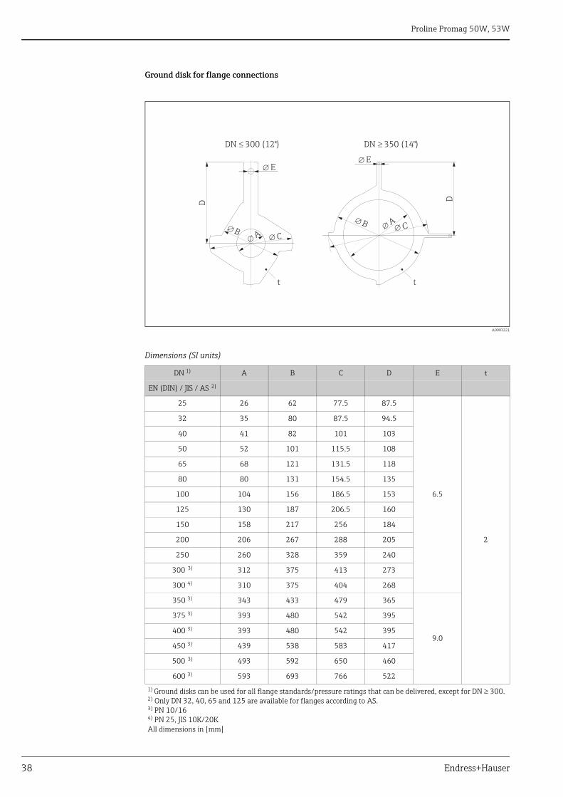
Ground disk for flange connections
A0003221
Dimensions (SI units)
DN 1) A B C D E t
EN (DIN) / JIS / AS 2)
25 26 62 77.5 87.5
6.5
2
32 35 80 87.5 94.5
40 41 82 101 103
50 52 101 115.5 108
65 68 121 131.5 118
80 80 131 154.5 135
100 104 156 186.5 153
125 130 187 206.5 160
150 158 217 256 184
200 206 267 288 205
250 260 328 359 240
300 3) 312 375 413 273
300 4) 310 375 404 268
350 3) 343 433 479 365
9.0
375 3) 393 480 542 395
400 3) 393 480 542 395
450 3) 439 538 583 417
500 3) 493 592 650 460
600 3) 593 693 766 522
1) Ground disks can be used for all flange standards/pressure ratings that can be delivered, except for DN 300.2) Only DN 32, 40, 65 and 125 are available for flanges according to AS.3) PN 10/164) PN 25, JIS 10K/20KAll dimensions in [mm]
D D
DN � 300 (12")
t
E�
B�
A�
C�
A�
B�
t
�DN 350 (14")
C�
E�
Proline Promag 50W, 53W
Endress+Hauser 39
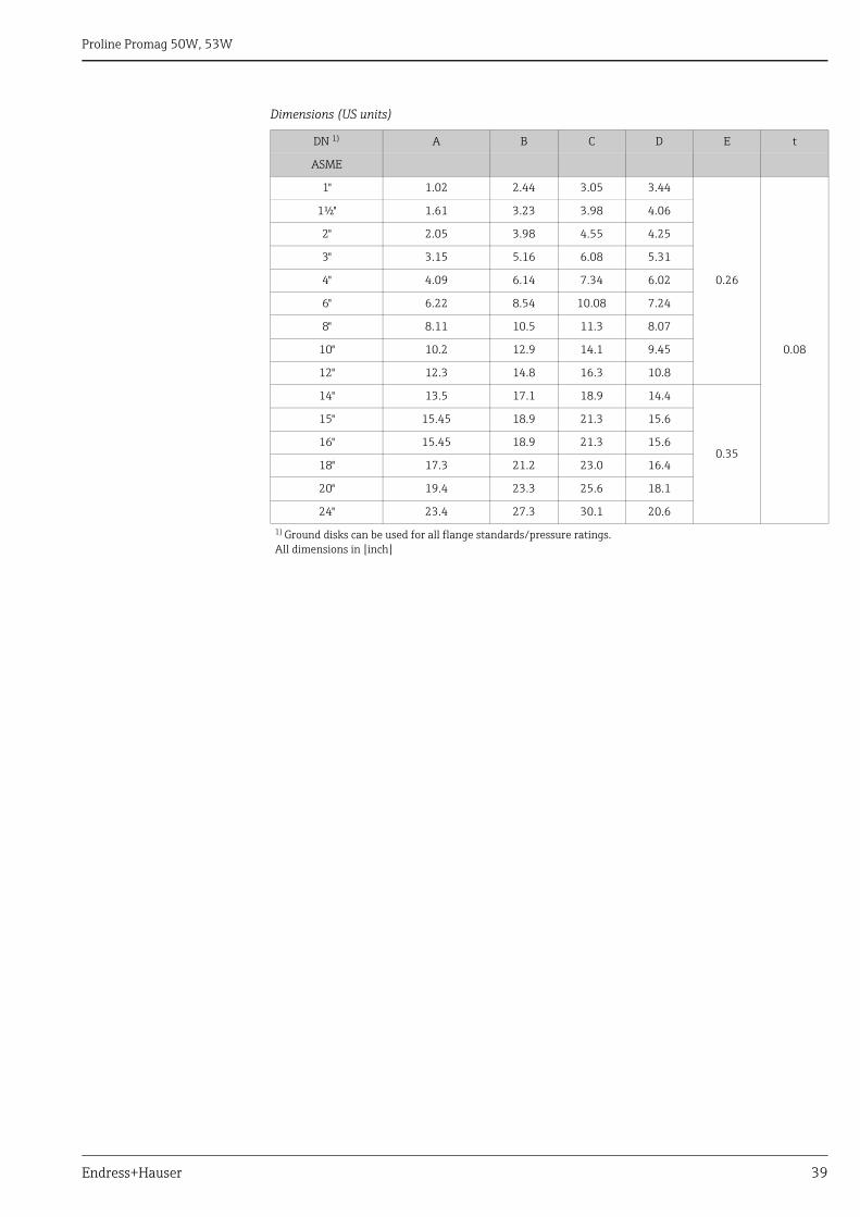
Dimensions (US units)
DN 1) A B C D E t
ASME
1" 1.02 2.44 3.05 3.44
0.26
0.08
1½" 1.61 3.23 3.98 4.06
2" 2.05 3.98 4.55 4.25
3" 3.15 5.16 6.08 5.31
4" 4.09 6.14 7.34 6.02
6" 6.22 8.54 10.08 7.24
8" 8.11 10.5 11.3 8.07
10" 10.2 12.9 14.1 9.45
12" 12.3 14.8 16.3 10.8
14" 13.5 17.1 18.9 14.4
0.35
15" 15.45 18.9 21.3 15.6
16" 15.45 18.9 21.3 15.6
18" 17.3 21.2 23.0 16.4
20" 19.4 23.3 25.6 18.1
24" 23.4 27.3 30.1 20.6
1) Ground disks can be used for all flange standards/pressure ratings.All dimensions in [inch]
Proline Promag 50W, 53W
40 Endress+Hauser
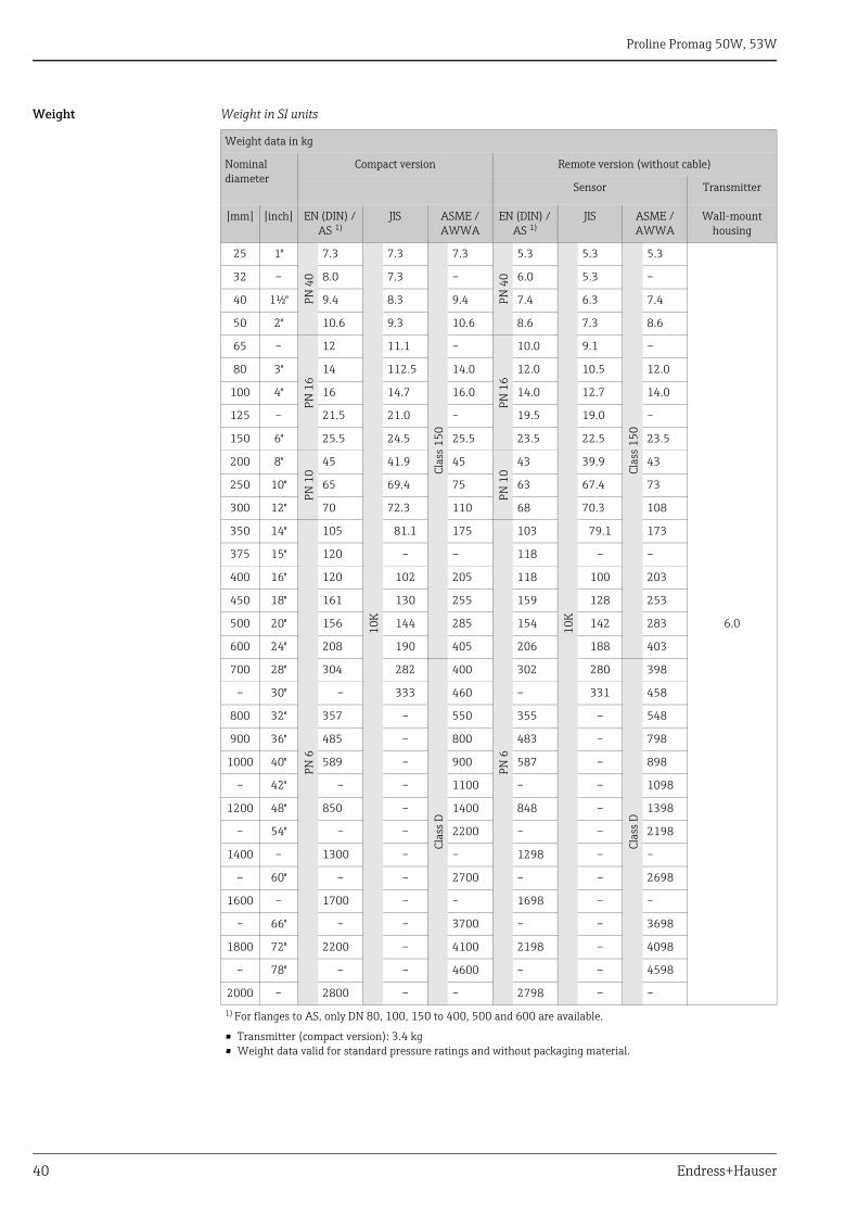
Weight Weight in SI units
Weight data in kg
Nominal diameter
Compact version Remote version (without cable)
Sensor Transmitter
[mm] [inch] EN (DIN) / AS 1)
JIS ASME /AWWA
EN (DIN) / AS 1)
JIS ASME / AWWA
Wall-mount housing
25 1"
PN 4
0
7.3
10K
7.3
Clas
s 15
0
7.3
PN 4
0
5.3
10K
5.3
Clas
s 15
0
5.3
6.0
32 – 8.0 7.3 – 6.0 5.3 –
40 1½" 9.4 8.3 9.4 7.4 6.3 7.4
50 2" 10.6 9.3 10.6 8.6 7.3 8.6
65 –
PN 1
6
12 11.1 –
PN 1
6
10.0 9.1 –
80 3" 14 112.5 14.0 12.0 10.5 12.0
100 4" 16 14.7 16.0 14.0 12.7 14.0
125 – 21.5 21.0 – 19.5 19.0 –
150 6" 25.5 24.5 25.5 23.5 22.5 23.5
200 8"
PN 1
0
45 41.9 45
PN 1
0
43 39.9 43
250 10" 65 69.4 75 63 67.4 73
300 12" 70 72.3 110 68 70.3 108
350 14"
PN 6
105 81.1 175
PN 6
103 79.1 173
375 15" 120 – – 118 – –
400 16" 120 102 205 118 100 203
450 18" 161 130 255 159 128 253
500 20" 156 144 285 154 142 283
600 24" 208 190 405 206 188 403
700 28" 304 282
Clas
s D
400 302 280
Clas
s D
398
– 30" – 333 460 – 331 458
800 32" 357 – 550 355 – 548
900 36" 485 – 800 483 – 798
1000 40" 589 – 900 587 – 898
– 42" – – 1100 – – 1098
1200 48" 850 – 1400 848 – 1398
– 54" – – 2200 – – 2198
1400 – 1300 – – 1298 – –
– 60" – – 2700 – – 2698
1600 – 1700 – – 1698 – –
– 66" – – 3700 – – 3698
1800 72" 2200 – 4100 2198 – 4098
– 78" – – 4600 – – 4598
2000 – 2800 – – 2798 – –
1) For flanges to AS, only DN 80, 100, 150 to 400, 500 and 600 are available.
• Transmitter (compact version): 3.4 kg• Weight data valid for standard pressure ratings and without packaging material.
Proline Promag 50W, 53W
Endress+Hauser 41
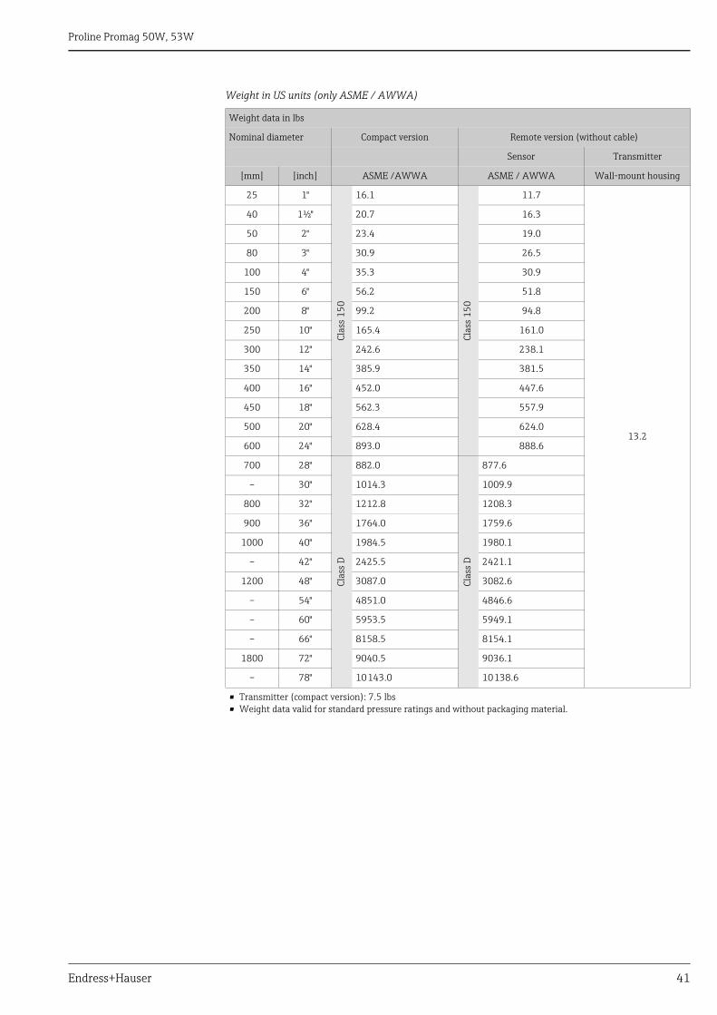
Weight in US units (only ASME / AWWA)
Weight data in lbs
Nominal diameter Compact version Remote version (without cable)
Sensor Transmitter
[mm] [inch] ASME /AWWA ASME / AWWA Wall-mount housing
25 1"
Clas
s 15
0
16.1
Clas
s 15
0
11.7
13.2
40 1½" 20.7 16.3
50 2" 23.4 19.0
80 3" 30.9 26.5
100 4" 35.3 30.9
150 6" 56.2 51.8
200 8" 99.2 94.8
250 10" 165.4 161.0
300 12" 242.6 238.1
350 14" 385.9 381.5
400 16" 452.0 447.6
450 18" 562.3 557.9
500 20" 628.4 624.0
600 24" 893.0 888.6
700 28"
Clas
s D
882.0Cl
ass
D877.6
– 30" 1014.3 1009.9
800 32" 1212.8 1208.3
900 36" 1764.0 1759.6
1000 40" 1984.5 1980.1
– 42" 2425.5 2421.1
1200 48" 3087.0 3082.6
– 54" 4851.0 4846.6
– 60" 5953.5 5949.1
– 66" 8158.5 8154.1
1800 72" 9040.5 9036.1
– 78" 10143.0 10138.6
• Transmitter (compact version): 7.5 lbs• Weight data valid for standard pressure ratings and without packaging material.
Proline Promag 50W, 53W
42 Endress+Hauser
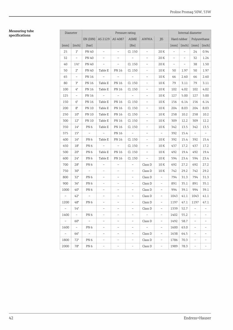
Measuring tube specifications
Diameter Pressure rating Internal diameter
EN (DIN) AS 2129 AS 4087 ASME AWWA JIS Hard rubber Polyurethane
[mm] [inch] [bar] [lbs] [mm] [inch] [mm] [inch]
25 1" PN 40 – – Cl. 150 – 20 K – – 24 0.94
32 – PN 40 – – – – 20 K – – 32 1.26
40 1½" PN 40 – – Cl. 150 – 20 K – – 38 1.50
50 2" PN 40 Table E PN 16 Cl. 150 – 10 K 50 1.97 50 1.97
65 – PN 16 – – – – 10 K 66 2.60 66 2.60
80 3" PN 16 Table E PN 16 Cl. 150 – 10 K 79 3.11 79 3.11
100 4" PN 16 Table E PN 16 Cl. 150 – 10 K 102 4.02 102 4.02
125 – PN 16 – – – – 10 K 127 5.00 127 5.00
150 6" PN 16 Table E PN 16 Cl. 150 – 10 K 156 6.14 156 6.14
200 8" PN 10 Table E PN 16 Cl. 150 – 10 K 204 8.03 204 8.03
250 10" PN 10 Table E PN 16 Cl. 150 – 10 K 258 10.2 258 10.2
300 12" PN 10 Table E PN 16 Cl. 150 – 10 K 309 12.2 309 12.2
350 14" PN 6 Table E PN 16 Cl. 150 – 10 K 342 13.5 342 13.5
375 15" – – PN 16 – – – 392 15.4 – –
400 16" PN 6 Table E PN 16 Cl. 150 – 10 K 392 15.4 392 15.4
450 18" PN 6 – – Cl. 150 – 10 K 437 17.2 437 17.2
500 20" PN 6 Table E PN 16 Cl. 150 – 10 K 492 19.4 492 19.4
600 24" PN 6 Table E PN 16 Cl. 150 – 10 K 594 23.4 594 23.4
700 28" PN 6 – – – Class D 10 K 692 27.2 692 27.2
750 30" – – – – Class D 10 K 742 29.2 742 29.2
800 32" PN 6 – – – Class D – 794 31.3 794 31.3
900 36" PN 6 – – – Class D – 891 35.1 891 35.1
1000 40" PN 6 – – – Class D – 994 39.1 994 39.1
– 42" – – – – Class D – 1043 41.1 1043 41.1
1200 48" PN 6 – – – Class D – 1197 47.1 1197 47.1
– 54" – – – Class D – 1339 52.7 – –
1400 – PN 6 – – – – – 1402 55.2 – –
– 60" – – – – Class D – 1492 58.7 – –
1600 – PN 6 – – – – – 1600 63.0 – –
– 66" – – – – Class D – 1638 64.5 – –
1800 72" PN 6 – – – Class D – 1786 70.3 – –
2000 78" PN 6 – – – Class D – 1989 78.3 – –
Proline Promag 50W, 53W
Endress+Hauser 43
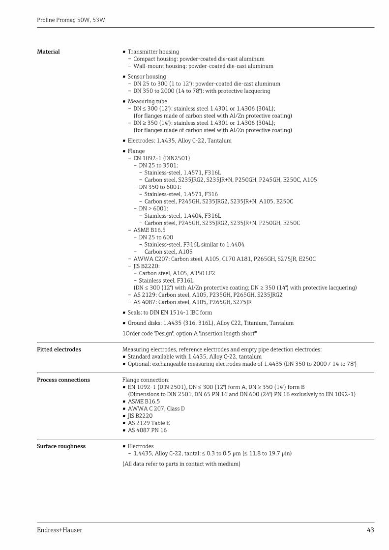
Material • Transmitter housing– Compact housing: powder-coated die-cast aluminum– Wall-mount housing: powder-coated die-cast aluminum
• Sensor housing– DN 25 to 300 (1 to 12"): powder-coated die-cast aluminum– DN 350 to 2000 (14 to 78"): with protective lacquering
• Measuring tube– DN 300 (12"): stainless steel 1.4301 or 1.4306 (304L);
(for flanges made of carbon steel with Al/Zn protective coating)– DN 350 (14"): stainless steel 1.4301 or 1.4306 (304L);
(for flanges made of carbon steel with Al/Zn protective coating)
• Electrodes: 1.4435, Alloy C-22, Tantalum
• Flange– EN 1092-1 (DIN2501)
– DN 25 to 3501:– Stainless-steel, 1.4571, F316L– Carbon steel, S235JRG2, S235JR+N, P250GH, P245GH, E250C, A105
– DN 350 to 6001: – Stainless-steel, 1.4571, F316– Carbon steel, P245GH, S235JRG2, S235JR+N, A105, E250C
– DN > 6001: – Stainless-steel, 1.4404, F316L– Carbon steel, P245GH, S235JRG2, S235JR+N, P250GH, E250C
– ASME B16.5 – DN 25 to 600
– Stainless-steel, F316L similar to 1.4404– Carbon steel, A105
– AWWA C207: Carbon steel, A105, Cl.70 A181, P265GH, S275JR, E250C– JIS B2220:
– Carbon steel, A105, A350 LF2– Stainless steel, F316L(DN ≤ 300 (12") with Al/Zn protective coating; DN ≥ 350 (14") with protective lacquering)
– AS 2129: Carbon steel, A105, P235GH, P265GH, S235JRG2– AS 4087: Carbon steel, A105, P265GH, S275JR
• Seals: to DIN EN 1514-1 IBC form
• Ground disks: 1.4435 (316, 316L), Alloy C22, Titanium, Tantalum
1Order code "Design", option A "insertion length short""
Fitted electrodes Measuring electrodes, reference electrodes and empty pipe detection electrodes:• Standard available with 1.4435, Alloy C-22, tantalum• Optional: exchangeable measuring electrodes made of 1.4435 (DN 350 to 2000 / 14 to 78")
Process connections Flange connection:• EN 1092-1 (DIN 2501), DN 300 (12") form A, DN 350 (14") form B
(Dimensions to DIN 2501, DN 65 PN 16 and DN 600 (24") PN 16 exclusively to EN 1092-1)• ASME B16.5• AWWA C 207, Class D• JIS B2220• AS 2129 Table E• AS 4087 PN 16
Surface roughness • Electrodes– 1.4435, Alloy C-22, tantal: 0.3 to 0.5 μm (11.8 to 19.7 μin)
(All data refer to parts in contact with medium)
Proline Promag 50W, 53W
44 Endress+Hauser
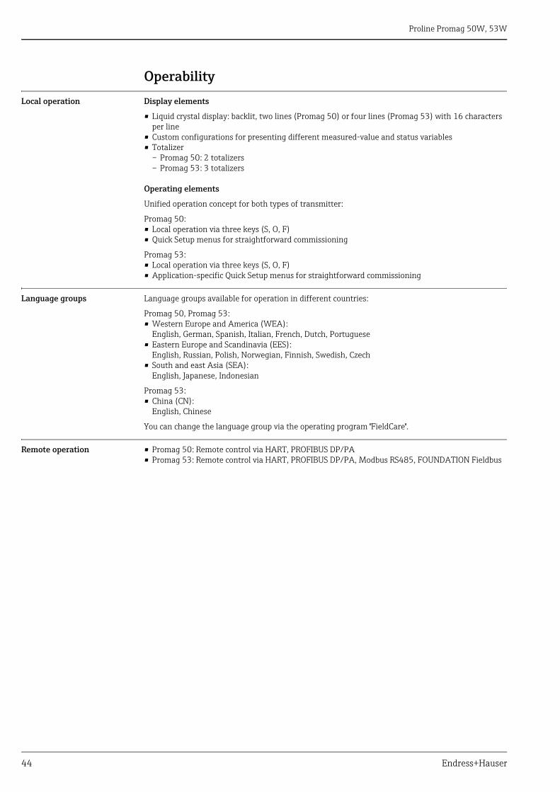
Operability
Local operation Display elements
• Liquid crystal display: backlit, two lines (Promag 50) or four lines (Promag 53) with 16 characters per line
• Custom configurations for presenting different measured-value and status variables• Totalizer
– Promag 50: 2 totalizers– Promag 53: 3 totalizers
Operating elements
Unified operation concept for both types of transmitter:
Promag 50:• Local operation via three keys (S, O, F)• Quick Setup menus for straightforward commissioning
Promag 53:• Local operation via three keys (S, O, F)• Application-specific Quick Setup menus for straightforward commissioning
Language groups Language groups available for operation in different countries:
Promag 50, Promag 53:• Western Europe and America (WEA):
English, German, Spanish, Italian, French, Dutch, Portuguese• Eastern Europe and Scandinavia (EES):
English, Russian, Polish, Norwegian, Finnish, Swedish, Czech• South and east Asia (SEA):
English, Japanese, Indonesian
Promag 53:• China (CN):
English, Chinese
You can change the language group via the operating program "FieldCare".
Remote operation • Promag 50: Remote control via HART, PROFIBUS DP/PA• Promag 53: Remote control via HART, PROFIBUS DP/PA, Modbus RS485, FOUNDATION Fieldbus
Proline Promag 50W, 53W
Endress+Hauser 45
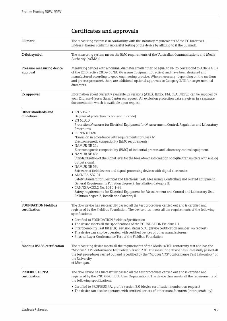
Certificates and approvals
CE mark The measuring system is in conformity with the statutory requirements of the EC Directives.Endress+Hauser confirms successful testing of the device by affixing to it the CE mark.
C-tick symbol The measuring system meets the EMC requirements of the "Australian Communications and Media Authority (ACMA)".
Pressure measuring device approval
Measuring devices with a nominal diameter smaller than or equal to DN 25 correspond to Article 4 (3) of the EC Directive 2014/68/EU (Pressure Equipment Directive) and have been designed and manufactured according to good engineering practice. Where necessary (depending on the medium and process pressure), there are additional optional approvals to Category II/III for larger nominal diameters.
Ex approval Information about currently available Ex versions (ATEX, IECEx, FM, CSA, NEPSI) can be supplied by your Endress+Hauser Sales Center on request. All explosion protection data are given in a separate documentation which is available upon request.
Other standards and guidelines
• EN 60529Degrees of protection by housing (IP code)
• EN 61010Protection Measures for Electrical Equipment for Measurement, Control, Regulation and Laboratory Procedures.
• IEC/EN 61326“Emission in accordance with requirements for Class A”.Electromagnetic compatibility (EMC requirements)
• NAMUR NE 21:Electromagnetic compatibility (EMC) of industrial process and laboratory control equipment.
• NAMUR NE 43:Standardization of the signal level for the breakdown information of digital transmitters with analog output signal.
• NAMUR NE 53:Software of field devices and signal-processing devices with digital electronics.
• ANSI/ISA-S82.01Safety Standard for Electrical and Electronic Test, Measuring, Controlling and related Equipment - General Requirements Pollution degree 2, Installation Category II.
• CAN/CSA-C22.2 No. 1010.1-92Safety requirements for Electrical Equipment for Measurement and Control and Laboratory Use.Pollution degree 2, Installation Category II
FOUNDATION Fieldbus certification
The flow device has successfully passed all the test procedures carried out and is certified and registered by the Fieldbus Foundation. The device thus meets all the requirements of the following specifications:
• Certified to FOUNDATION Fieldbus Specification• The device meets all the specifications of the FOUNDATION Fieldbus H1.• Interoperability Test Kit (ITK), revision status 5.01 (device certification number: on request)• The device can also be operated with certified devices of other manufacturers• Physical Layer Conformance Test of the Fieldbus Foundation
Modbus RS485 certification The measuring device meets all the requirements of the Modbus/TCP conformity test and has the “Modbus/TCP Conformance Test Policy, Version 2.0”. The measuring device has successfully passed all the test procedures carried out and is certified by the “Modbus/TCP Conformance Test Laboratory” of the Universityof Michigan.
PROFIBUS DP/PA certification
The flow device has successfully passed all the test procedures carried out and is certified and registered by the PNO (PROFIBUS User Organisation). The device thus meets all the requirements of the following specifications:
• Certified to PROFIBUS PA, profile version 3.0 (device certification number: on request)• The device can also be operated with certified devices of other manufacturers (interoperability)

Proline Promag 50W, 53W
46 Endress+Hauser
Ordering informationYour Endress+Hauser service organization can provide detailed ordering information and information on the order codes on request.
AccessoriesVarious accessories, which can be ordered separately from Endress+Hauser, are available for the transmitter and the sensor. Your Endress+Hauser service organization can provide detailed information on the order codes in question.
Documentation• Flow Measurement (FA005D/06)• Operating Instructions Promag 50 (BA046D/06 and BA049D/06)• Operating Instructions Promag 50 PROFIBUS PA (BA055D/06 and BA056D/06)• Operating Instructions Promag 53 (BA047D/06 and BA048D/06)• Operating Instructions Promag 53 FOUNDATION Fieldbus (BA051D/06 and BA052D/06)• Operating Instructions Promag 53 Modbus RS485 (BA117D/06 and BA118D/06)• Operating Instructions Promag 53 PROFIBUS DP/PA (BA053D/06 and BA054D/06)• Supplementary documentation on Ex-ratings: ATEX, IECEx, FM, CSA, NEPSI
Registered trademarksHART® Registered trademark of the HART Communication Foundation, Austin, USA
PROFIBUS® Registered trademark of the PROFIBUS Nutzerorganisation e.V., Karlsruhe, D
FOUNDATION™ FieldbusRegistered trademark of the Fieldbus Foundation, Austin, USA
Modbus® Registered trademark of the Modbus Organisation
HistoROM™, S-DAT®, T-DAT™, F-CHIP®, FieldCare®, Fieldcheck®, FieldXpert™, Applicator®Registered or registration-pending trademarks of the Endress+Hauser Flowtec Group

www.addresses.endress.com