
Promag 10L1F
36
TI00100D/06/EN/14.11 71136637 Technical Information Proline Promag 10L Electromagnetic Flow Measuring System Flow measurement of liquids in water or wastewater applications Application Electromagnetic flowmeter for bidirectional measurement of liquids with a minimum conductivity of 50 μS/cm: • Drinking water • Wastewater • Sewage sludge • Flow measurement up to 40000 m³/h (175000 gal/min) • Fluid temperature up to +90 °C (+194 °F) • Process pressures up to 16 bar (232 psi) • Lengths in accordance with DVGW/ISO Application-specific lining of the measuring pipe from polyurethane, hard rubber or PTFE with the following drinking water permissions: • KTW • WRAS • NSF • ACS Your benefits Promag measuring devices offer you cost-effective flow measurement with a high degree of accuracy for a wide range of process conditions. The uniform Proline transmitter concept comprises: • High degree of reliability and measuring stability • Uniform operating concept The tried-and-tested Promag sensors offer: • No pressure loss • Not sensitive to vibrations • Simple installation and commissioning • Flexible flange mounting
-
Upload
charles-martin -
Category
Documents
-
view
184 -
download
2
Transcript of Promag 10L1F
TI00100D/06/EN/14.11
71136637
Technical Information
Proline Promag 10L
Electromagnetic Flow Measuring System
Flow measurement of liquids
in water or wastewater applications
Application
Electromagnetic flowmeter for bidirectional
measurement of liquids with a minimum
conductivity of 50 μS/cm:
• Drinking water
• Wastewater
• Sewage sludge
• Flow measurement up to
40000 m³/h (175000 gal/min)
• Fluid temperature up to +90 °C (+194 °F)
• Process pressures up to 16 bar (232 psi)
• Lengths in accordance with DVGW/ISO
Application-specific lining of the measuring pipe from
polyurethane, hard rubber or PTFE with the following
drinking water permissions:
• KTW
• WRAS
• NSF
• ACS
Your benefits
Promag measuring devices offer you cost-effective
flow measurement with a high degree of accuracy
for a wide range of process conditions.
The uniform Proline transmitter concept comprises:
• High degree of reliability and measuring stability
• Uniform operating concept
The tried-and-tested Promag sensors offer:
• No pressure loss
• Not sensitive to vibrations
• Simple installation and commissioning
• Flexible flange mounting
Proline Promag 10L
2 Endress+Hauser
Table of contents
Function and system design. . . . . . . . . . . . . . . . . . . . . 3
Measuring principle . . . . . . . . . . . . . . . . . . . . . . . . . . . . . . . . . . . 3
Measuring system . . . . . . . . . . . . . . . . . . . . . . . . . . . . . . . . . . . . . 3
Input . . . . . . . . . . . . . . . . . . . . . . . . . . . . . . . . . . . . . . 3
Measured variable . . . . . . . . . . . . . . . . . . . . . . . . . . . . . . . . . . . . 3
Measuring ranges . . . . . . . . . . . . . . . . . . . . . . . . . . . . . . . . . . . . . 3
Operable flow range . . . . . . . . . . . . . . . . . . . . . . . . . . . . . . . . . . . 3
Output . . . . . . . . . . . . . . . . . . . . . . . . . . . . . . . . . . . . . 4
Output signal . . . . . . . . . . . . . . . . . . . . . . . . . . . . . . . . . . . . . . . . 4
Signal on alarm . . . . . . . . . . . . . . . . . . . . . . . . . . . . . . . . . . . . . . 4
Load . . . . . . . . . . . . . . . . . . . . . . . . . . . . . . . . . . . . . . . . . . . . . . 4
Low flow cutoff . . . . . . . . . . . . . . . . . . . . . . . . . . . . . . . . . . . . . . 4
Galvanic isolation . . . . . . . . . . . . . . . . . . . . . . . . . . . . . . . . . . . . . 4
Power supply. . . . . . . . . . . . . . . . . . . . . . . . . . . . . . . . 4
Electrical connection, measuring unit . . . . . . . . . . . . . . . . . . . . . . 4
Electrical connection,
terminal assignment . . . . . . . . . . . . . . . . . . . . . . . . . . . . . . . . . . . 5
Electrical connection,
remote version . . . . . . . . . . . . . . . . . . . . . . . . . . . . . . . . . . . . . . . 5
Supply voltage (power supply) . . . . . . . . . . . . . . . . . . . . . . . . . . . 5
Cable entry . . . . . . . . . . . . . . . . . . . . . . . . . . . . . . . . . . . . . . . . . 5
Remote version cable specifications . . . . . . . . . . . . . . . . . . . . . . . . 6
Power consumption . . . . . . . . . . . . . . . . . . . . . . . . . . . . . . . . . . . 6
Power supply failure . . . . . . . . . . . . . . . . . . . . . . . . . . . . . . . . . . . 6
Potential equalization . . . . . . . . . . . . . . . . . . . . . . . . . . . . . . . . . . 7
Performance characteristics. . . . . . . . . . . . . . . . . . . . . 8
Reference operating conditions . . . . . . . . . . . . . . . . . . . . . . . . . . . 8
Maximum measured error . . . . . . . . . . . . . . . . . . . . . . . . . . . . . . 8
Repeatability . . . . . . . . . . . . . . . . . . . . . . . . . . . . . . . . . . . . . . . . . 8
Operating conditions: Installations . . . . . . . . . . . . . . . 9
Installation instructions . . . . . . . . . . . . . . . . . . . . . . . . . . . . . . . . . 9
Inlet and outlet run . . . . . . . . . . . . . . . . . . . . . . . . . . . . . . . . . . 12
Adapters . . . . . . . . . . . . . . . . . . . . . . . . . . . . . . . . . . . . . . . . . . . 13
Length of connecting cable . . . . . . . . . . . . . . . . . . . . . . . . . . . . . 14
Operating conditions: Environment. . . . . . . . . . . . . . 15
Ambient temperature range . . . . . . . . . . . . . . . . . . . . . . . . . . . . 15
Storage temperature . . . . . . . . . . . . . . . . . . . . . . . . . . . . . . . . . . 15
Degree of protection . . . . . . . . . . . . . . . . . . . . . . . . . . . . . . . . . . 15
Shock and vibration resistance . . . . . . . . . . . . . . . . . . . . . . . . . . 15
Electromagnetic compatibility (EMC) . . . . . . . . . . . . . . . . . . . . . 15
Operating conditions: Process . . . . . . . . . . . . . . . . . . 16
Medium temperature range . . . . . . . . . . . . . . . . . . . . . . . . . . . . 16
Conductivity . . . . . . . . . . . . . . . . . . . . . . . . . . . . . . . . . . . . . . . 16
Medium pressure range
(nominal pressure) . . . . . . . . . . . . . . . . . . . . . . . . . . . . . . . . . . 16
Pressure tightness . . . . . . . . . . . . . . . . . . . . . . . . . . . . . . . . . . . . 16
Limiting flow . . . . . . . . . . . . . . . . . . . . . . . . . . . . . . . . . . . . . . . 16
Pressure loss . . . . . . . . . . . . . . . . . . . . . . . . . . . . . . . . . . . . . . . . 17
Mechanical construction . . . . . . . . . . . . . . . . . . . . . . 18
Design, dimensions . . . . . . . . . . . . . . . . . . . . . . . . . . . . . . . . . . 18
Weight . . . . . . . . . . . . . . . . . . . . . . . . . . . . . . . . . . . . . . . . . . . 27
Measuring tube specifications . . . . . . . . . . . . . . . . . . . . . . . . . . . 30
Material . . . . . . . . . . . . . . . . . . . . . . . . . . . . . . . . . . . . . . . . . . . 31
Material load diagram . . . . . . . . . . . . . . . . . . . . . . . . . . . . . . . . 32
Fitted electrodes . . . . . . . . . . . . . . . . . . . . . . . . . . . . . . . . . . . . 34
Process connections . . . . . . . . . . . . . . . . . . . . . . . . . . . . . . . . . . 34
Surface roughness . . . . . . . . . . . . . . . . . . . . . . . . . . . . . . . . . . . 34
Human interface . . . . . . . . . . . . . . . . . . . . . . . . . . . . 34
Display elements . . . . . . . . . . . . . . . . . . . . . . . . . . . . . . . . . . . . 34
Operating elements . . . . . . . . . . . . . . . . . . . . . . . . . . . . . . . . . . 34
Remote operation . . . . . . . . . . . . . . . . . . . . . . . . . . . . . . . . . . . . 34
Certificates and approvals . . . . . . . . . . . . . . . . . . . . . 35
CE mark . . . . . . . . . . . . . . . . . . . . . . . . . . . . . . . . . . . . . . . . . . 35
C-tick mark . . . . . . . . . . . . . . . . . . . . . . . . . . . . . . . . . . . . . . . . 35
Drinking water approval . . . . . . . . . . . . . . . . . . . . . . . . . . . . . . . 35
Other standards and guidelines . . . . . . . . . . . . . . . . . . . . . . . . . . 35
Ordering information. . . . . . . . . . . . . . . . . . . . . . . . . 35
Accessories . . . . . . . . . . . . . . . . . . . . . . . . . . . . . . . . 35
Documentation . . . . . . . . . . . . . . . . . . . . . . . . . . . . . 35
Registered trademarks. . . . . . . . . . . . . . . . . . . . . . . . 35
Proline Promag 10L
Endress+Hauser 3
Function and system design
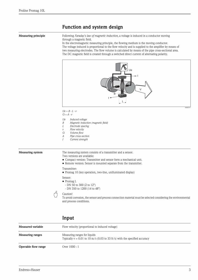
Measuring principle Following Faraday's law of magnetic induction, a voltage is induced in a conductor moving
through a magnetic field.
In the electromagnetic measuring principle, the flowing medium is the moving conductor.
The voltage induced is proportional to the flow velocity and is supplied to the amplifier by means of
two measuring electrodes. The flow volume is calculated by means of the pipe cross-sectional area.
The DC magnetic field is created through a switched direct current of alternating polarity.
A0003191
Ue = B · L · v
Q = A · v
Ue Induced voltage
B Magnetic induction (magnetic field)
L Electrode spacing
v Flow velocity
Q Volume flow
A Pipe cross-section
I Current strength
Measuring system The measuring system consists of a transmitter and a sensor.
Two versions are available:
• Compact version: Transmitter and sensor form a mechanical unit.
• Remote version: Sensor is mounted separate from the transmitter.
Transmitter:
• Promag 10 (key operation, two-line, unilluminated display)
Sensor:
• Promag L
- DN 50 to 300 (2 to 12")
- DN 350 to 1200 (14 to 48")
" Caution!
To avoid corrosion, the sensor and process connection material must be selected considering the environmental
and process conditions.
Input
Measured variable Flow velocity (proportional to induced voltage)
Measuring ranges Measuring ranges for liquids
Typically v = 0.01 to 10 m/s (0.03 to 33 ft/s) with the specified accuracy
Operable flow range Over 1000 : 1
Ue
I
I
B
L
V
Proline Promag 10L
4 Endress+Hauser
Output
Output signal Current output
• Galvanically isolated
• Active: 4 to 20 mA, RL < 700 (for HART: RL 250 )
• Full scale value adjustable
• Temperature coefficient: typ. 2 μA/°C, resolution: 1.5 μA
Pulse/status output
• Galvanically isolated
• Passive: 30 V DC / 250 mA
• Open collector
• Can be configured as:
– Pulse output: Pulse value and pulse polarity can be selected, max. pulse width adjustable (5 to 2000 ms),
pulse frequency max. 100 Hz
– Status output: for example, can be configured for error messages, empty pipe detection, flow recognition,
limit value
Signal on alarm • Current output Failsafe mode can be selected (e.g. in accordance with NAMUR Recommendation NE 43)
• Pulse output Failsafe mode can be selected
• Status output "Not conductive" in the event of fault or power supply failure
Load È Section "output signal"
Low flow cutoff Switch-on points for low flow are selectable.
Galvanic isolation All circuits for inputs, outputs and power supply are galvanically isolated from each other.
Power supply
Electrical connection,
measuring unit
A0003192
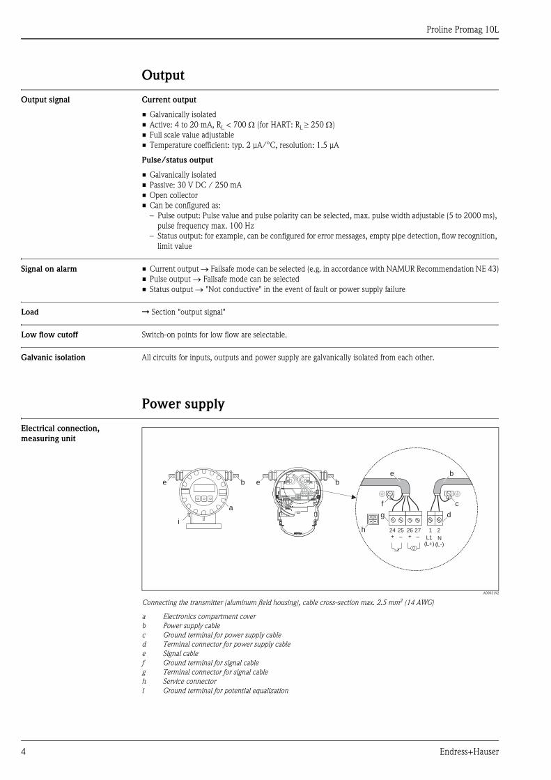
Connecting the transmitter (aluminum field housing), cable cross-section max. 2.5 mm2 (14 AWG)
a Electronics compartment cover
b Power supply cable
c Ground terminal for power supply cable
d Terminal connector for power supply cable
e Signal cable
f Ground terminal for signal cable
g Terminal connector for signal cable
h Service connector
i Ground terminal for potential equalization
b
a
e e b
2127–
25–
26+
24+ L1
(L+)N
(L-)
e
g
b
d
hi
cf
Proline Promag 10L
Endress+Hauser 5
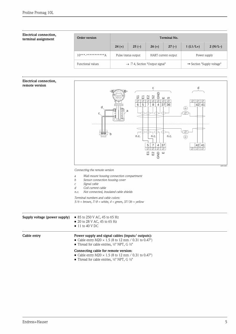
Electrical connection,
terminal assignment
Electrical connection,
remote version
A0012461
Connecting the remote version
a Wall-mount housing connection compartment
b Sensor connection housing cover
c Signal cable
d Coil current cable
n.c. Not connected, insulated cable shields
Terminal numbers and cable colors:
5/6 = brown, 7/8 = white, 4 = green, 37/36 = yellow
Supply voltage (power supply) • 85 to 250 V AC, 45 to 65 Hz
• 20 to 28 V AC, 45 to 65 Hz
• 11 to 40 V DC
Cable entry Power supply and signal cables (inputs/ outputs):
• Cable entry M20 × 1.5 (8 to 12 mm / 0.31 to 0.47")
• Thread for cable entries, ½" NPT, G ½"
Connecting cable for remote version:
• Cable entry M20 × 1.5 (8 to 12 mm / 0.31 to 0.47")
• Thread for cable entries, ½" NPT, G ½"
Order version Terminal No.
24 (+) 25 (–) 26 (+) 27 (–) 1 (L1/L+) 2 (N/L–)
10***-***********A Pulse/status output HART current output Power supply
Functional values ä 4, Section "Output signal" È Section "Supply voltage"
bn.c.
S1
E1
E2
S2
GN
D
E S
42 416 5 7 8 4 37 36
dc
ad
c
E1
E2
GN
D E
5 7 4 37 42 41
n.c. n.c.
Proline Promag 10L
6 Endress+Hauser
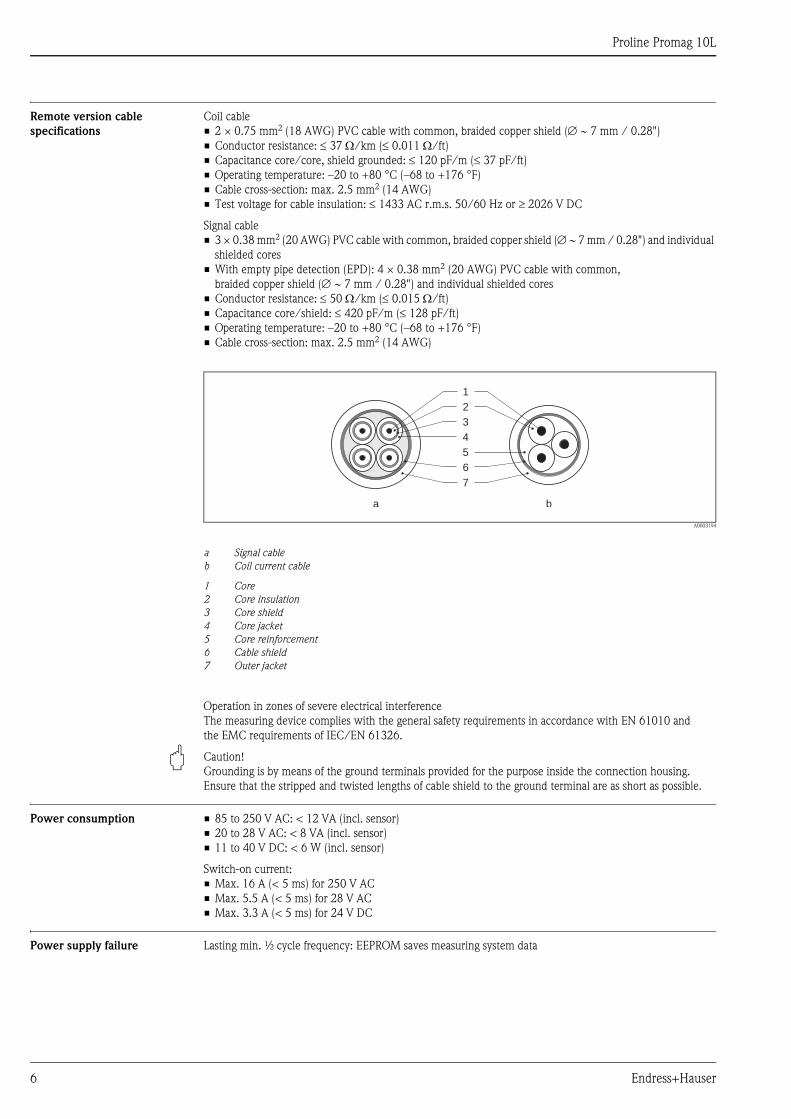
Remote version cable
specifications
Coil cable
• 2 × 0.75 mm2 (18 AWG) PVC cable with common, braided copper shield ( 7 mm / 0.28")
• Conductor resistance: 37 /km (0.011 /ft)
• Capacitance core/core, shield grounded: 120 pF/m (37 pF/ft)
• Operating temperature: –20 to +80 °C (–68 to +176 °F)
• Cable cross-section: max. 2.5 mm2 (14 AWG)
• Test voltage for cable insulation: 1433 AC r.m.s. 50/60 Hz or 2026 V DC
Signal cable
• 3 × 0.38 mm2 (20 AWG) PVC cable with common, braided copper shield ( 7 mm / 0.28") and individual
shielded cores
• With empty pipe detection (EPD): 4 × 0.38 mm2 (20 AWG) PVC cable with common,
braided copper shield ( 7 mm / 0.28") and individual shielded cores
• Conductor resistance: 50 /km (0.015 /ft)
• Capacitance core/shield: 420 pF/m (128 pF/ft)
• Operating temperature: –20 to +80 °C (–68 to +176 °F)
• Cable cross-section: max. 2.5 mm2 (14 AWG)
A0003194
a Signal cable
b Coil current cable
1 Core
2 Core insulation
3 Core shield
4 Core jacket
5 Core reinforcement
6 Cable shield
7 Outer jacket
Operation in zones of severe electrical interference
The measuring device complies with the general safety requirements in accordance with EN 61010 and
the EMC requirements of IEC/EN 61326.
" Caution!
Grounding is by means of the ground terminals provided for the purpose inside the connection housing.
Ensure that the stripped and twisted lengths of cable shield to the ground terminal are as short as possible.
Power consumption • 85 to 250 V AC: < 12 VA (incl. sensor)
• 20 to 28 V AC: < 8 VA (incl. sensor)
• 11 to 40 V DC: < 6 W (incl. sensor)
Switch-on current:
• Max. 16 A (< 5 ms) for 250 V AC
• Max. 5.5 A (< 5 ms) for 28 V AC
• Max. 3.3 A (< 5 ms) for 24 V DC
Power supply failure Lasting min. ½ cycle frequency: EEPROM saves measuring system data
1
2
3
4
5
6
7
a b
Proline Promag 10L
Endress+Hauser 7
Potential equalization
# Warning!
The measuring system must be included in the potential equalization.
Perfect measurement is only ensured when the fluid and the sensor have the same electrical potential. This is
ensured by the reference electrode integrated in the sensor as standard.
The following should also be taken into consideration for potential equalization:
• Internal grounding concepts in the company
• Operating conditions, such as the material/ grounding of the pipes (see table)
Standard situation
Special situations
Operating conditions Potential equalization
When using the measuring device in a:
• Metal, grounded pipe
Potential equalization takes place via the ground terminal of the
transmitter.
! Note!
When installing in metal pipes, we recommend you connect the
ground terminal of the transmitter housing with the piping.
A0010831
Via the ground terminal of the transmitter
Operating conditions Potential equalization
When using the measuring device in a:
• Metal pipe that is not grounded
This connection method also applies in situations where:
• Customary potential equalization cannot be ensured.
• Excessively high equalizing currents can be expected.
Both sensor flanges are connected to the pipe flange by means of
a ground cable (copper wire, at least 6 mm² / 0.0093 in²) and
grounded. Connect the transmitter or sensor connection
housing, as applicable, to ground potential by means of the
ground terminal provided for the purpose.
The ground cable is mounted directly on the conductive flange
coating with the flange screws.
! Note!
The ground cable for flange-to-flange connections can be
ordered separately as an accessory from Endress+Hauser.
A0011567
Via the ground terminal of the transmitter and the
flanges of the pipe
When using the measuring device in a:
• Plastic pipe
• Pipe with insulating lining
This connection method also applies in situations where:
• Customary potential equalization cannot be ensured.
• Excessively high equalizing currents can be expected.
Potential equalization takes place using additional ground disks,
which are connected to the ground terminal via a ground cable
(copper wire, at least 6 mm² / 0.0093 in²). When installing the
ground disks, please comply with the enclosed Installation
Instructions.A0010833
Via the ground terminal of the transmitter and the
optionally available ground disks
Proline Promag 10L
8 Endress+Hauser
Performance characteristics
Reference operating
conditions
As per DIN EN 29104 and VDI/VDE 2641:
• Fluid temperature: +28 °C ± 2 K (+82 °F ± 2 K)
• Ambient temperature: +22 °C ±2 K (+72 °F ± 2 K)
• Warm-up period: 30 minutes
Installation conditions:
• Inlet run > 10 × DN
• Outlet run > 5 × DN
• Sensor and transmitter grounded.
• The sensor is centered in the pipe.
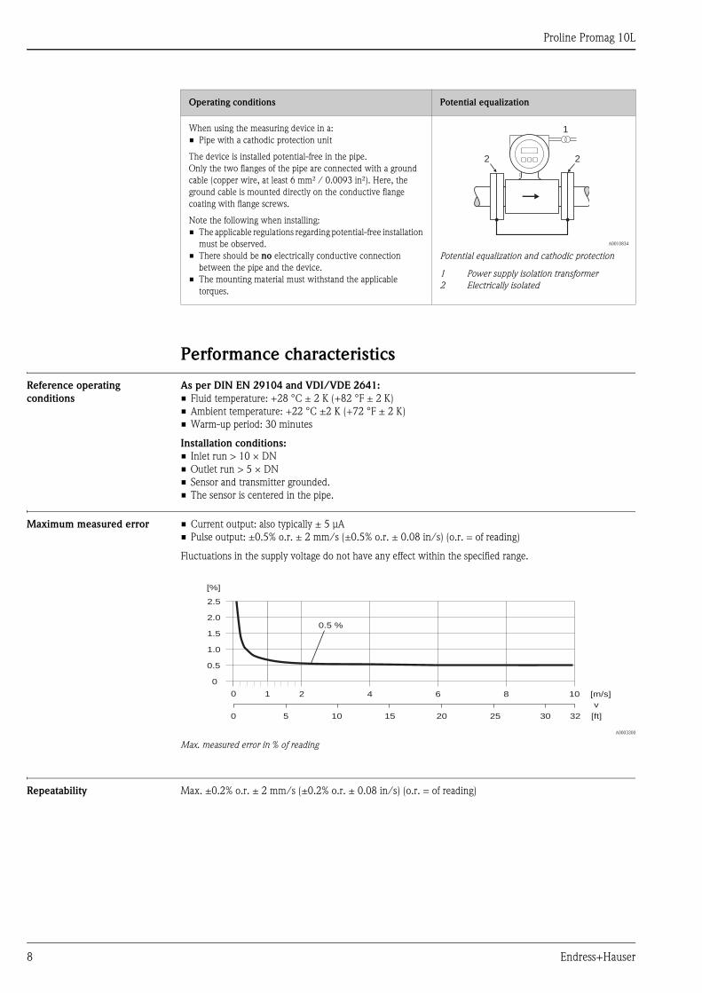
Maximum measured error • Current output: also typically ± 5 μA
• Pulse output: ±0.5% o.r. ± 2 mm/s (±0.5% o.r. ± 0.08 in/s) (o.r. = of reading)
Fluctuations in the supply voltage do not have any effect within the specified range.
A0003200
Max. measured error in % of reading
Repeatability Max. ±0.2% o.r. ± 2 mm/s (±0.2% o.r. ± 0.08 in/s) (o.r. = of reading)
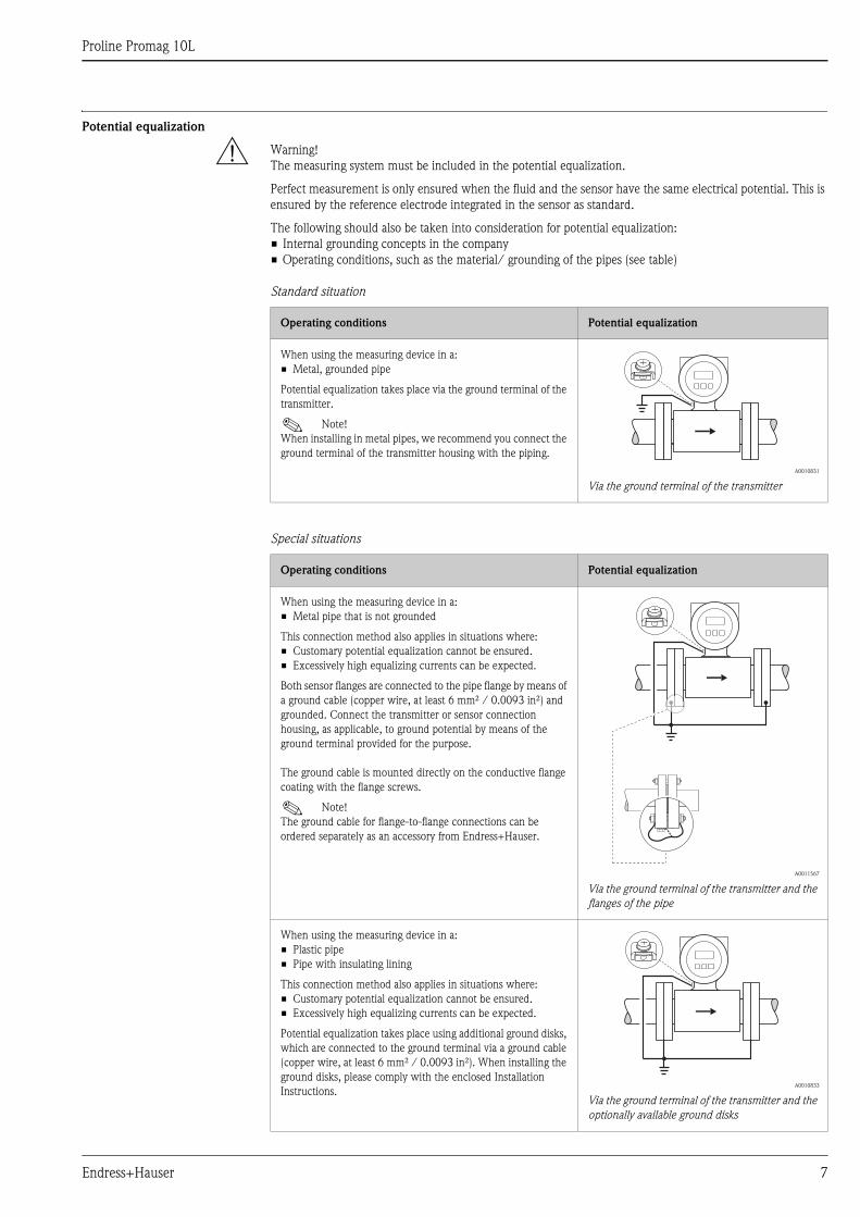
When using the measuring device in a:
• Pipe with a cathodic protection unit
The device is installed potential-free in the pipe.
Only the two flanges of the pipe are connected with a ground
cable (copper wire, at least 6 mm² / 0.0093 in²). Here, the
ground cable is mounted directly on the conductive flange
coating with flange screws.
Note the following when installing:
• The applicable regulations regarding potential-free installation
must be observed.
• There should be no electrically conductive connection
between the pipe and the device.
• The mounting material must withstand the applicable
torques.
A0010834
Potential equalization and cathodic protection
1 Power supply isolation transformer
2 Electrically isolated
Operating conditions Potential equalization
1
2 2
2.5
[%]
2.0
1.5
1.0
0.5
0
0.5 %
0 1 2 4 6 8 10 [m/s]
v
5 10 15 20 25 30 32 [ft]0
Proline Promag 10L
Endress+Hauser 9
Operating conditions: Installations
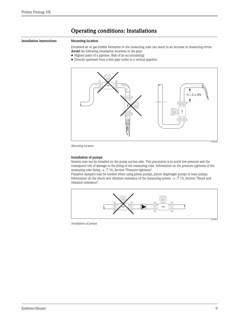
Installation instructions Mounting location
Entrained air or gas bubble formation in the measuring tube can result in an increase in measuring errors.
Avoid the following installation locations in the pipe:
• Highest point of a pipeline. Risk of air accumulating!
• Directly upstream from a free pipe outlet in a vertical pipeline.
A0003202
Mounting location
Installation of pumps
Sensors may not be installed on the pump suction side. This precaution is to avoid low pressure and the
consequent risk of damage to the lining of the measuring tube. Information on the pressure tightness of the
measuring tube lining ä 16, Section "Pressure tightness".
Pulsation dampers may be needed when using piston pumps, piston diaphragm pumps or hose pumps.
Information on the shock and vibration resistance of the measuring system ä 15, Section "Shock and
vibration resistance".
A0003203
Installation of pumps
h 2 x DN�

Proline Promag 10L
10 Endress+Hauser
Partially filled pipes
Partially filled pipes with gradients necessitate a drain-type configuration.
The empty pipe detection function (EPD) provides additional security in detecting empty or partially filled
pipes.
" Caution!
Risk of solids accumulating. Do not install the sensor at the lowest point in the drain. It is advisable to install a
cleaning valve.
A0003204
Installation with partially filled pipes
Down pipes
Install a siphon or a vent valve downstream of the sensor in down pipes h 5 m (16.4 ft). This precaution is
to avoid low pressure and the consequent risk of damage to the lining of the measuring tube. This measure also
prevents the liquid current stopping in the pipe which could cause air locks. Information on the pressure
tightness of the measuring tube lining ä 16, Section "Pressure tightness".
A0008157
Installation measures for vertical pipes
1 Vent valve
2 Pipe siphon
h Length of the down pipe
� 5 x DN
� 2 x DN
h
2
1
Proline Promag 10L
Endress+Hauser 11
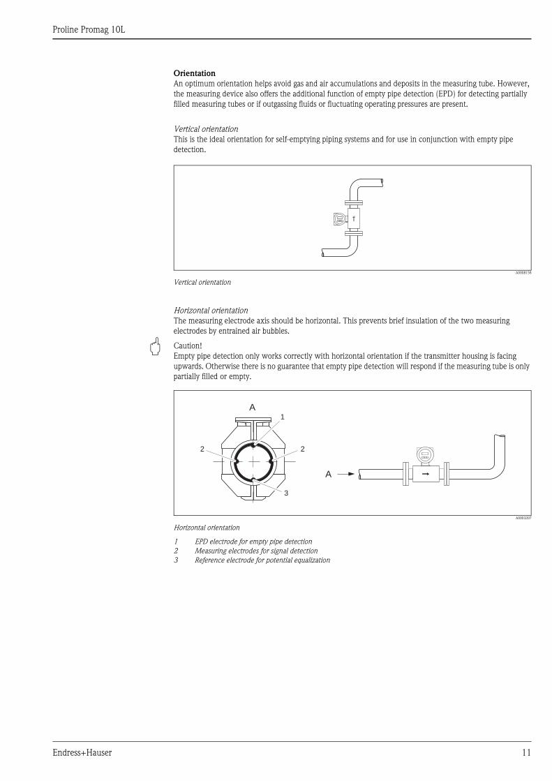
Orientation
An optimum orientation helps avoid gas and air accumulations and deposits in the measuring tube. However,
the measuring device also offers the additional function of empty pipe detection (EPD) for detecting partially
filled measuring tubes or if outgassing fluids or fluctuating operating pressures are present.
Vertical orientation
This is the ideal orientation for self-emptying piping systems and for use in conjunction with empty pipe
detection.
A0008158
Vertical orientation
Horizontal orientation
The measuring electrode axis should be horizontal. This prevents brief insulation of the two measuring
electrodes by entrained air bubbles.
" Caution!
Empty pipe detection only works correctly with horizontal orientation if the transmitter housing is facing
upwards. Otherwise there is no guarantee that empty pipe detection will respond if the measuring tube is only
partially filled or empty.
A0003207
Horizontal orientation
1 EPD electrode for empty pipe detection
2 Measuring electrodes for signal detection
3 Reference electrode for potential equalization
A1
2 2
A
3
Proline Promag 10L
12 Endress+Hauser
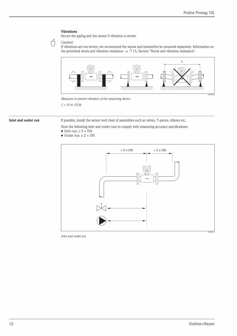
Vibrations
Secure the piping and the sensor if vibration is severe.
" Caution!
If vibrations are too severe, we recommend the sensor and transmitter be mounted separately. Information on
the permitted shock and vibration resistance ä 15, Section "Shock and vibration resistance".
A0003208
Measures to prevent vibration of the measuring device
L > 10 m (33 ft)
Inlet and outlet run If possible, install the sensor well clear of assemblies such as valves, T-pieces, elbows etc.
Note the following inlet and outlet runs to comply with measuring accuracy specifications:
• Inlet run: 5 × DN
• Outlet run: 2 × DN
A0003210
Inlet and outlet run
L
5 x DN� � 2 x DN
Proline Promag 10L
Endress+Hauser 13
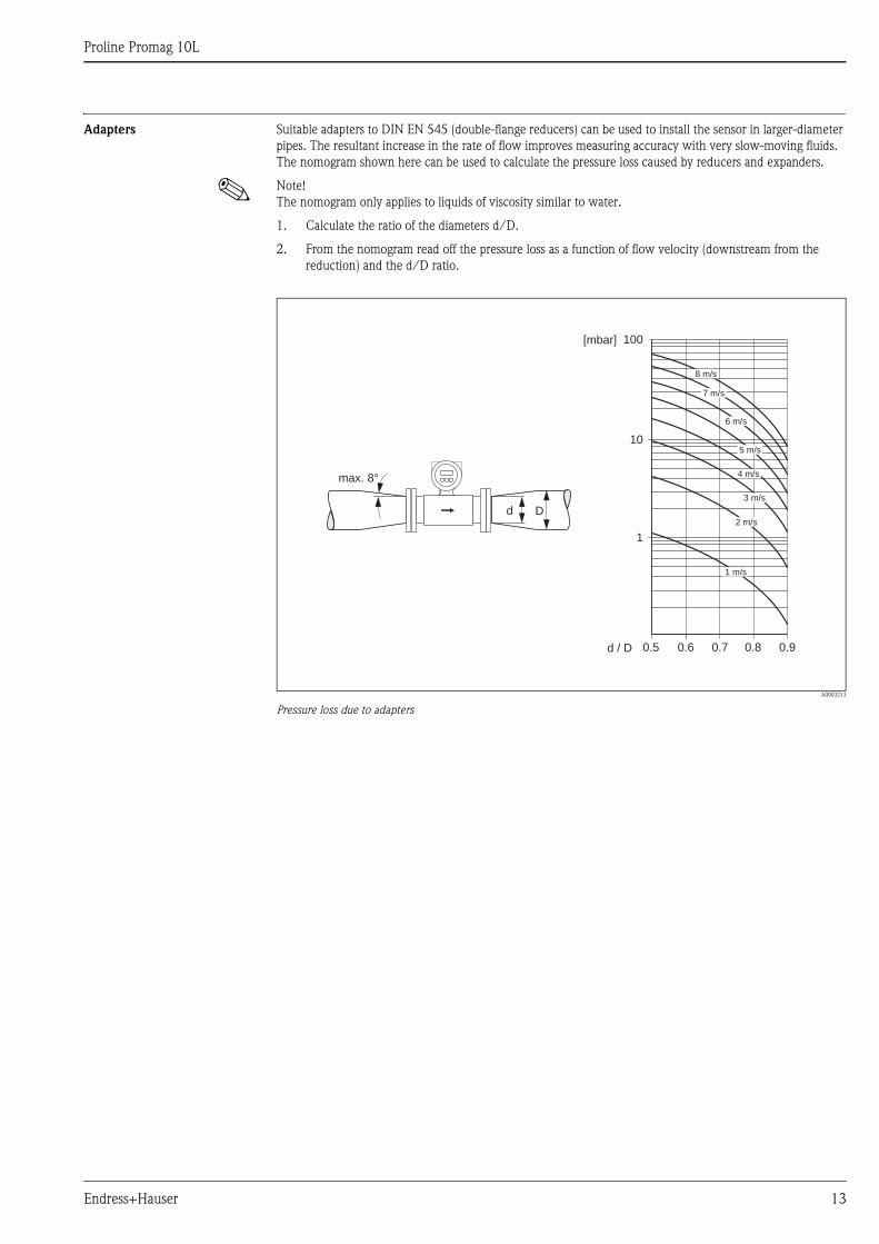
Adapters Suitable adapters to DIN EN 545 (double-flange reducers) can be used to install the sensor in larger-diameter
pipes. The resultant increase in the rate of flow improves measuring accuracy with very slow-moving fluids.
The nomogram shown here can be used to calculate the pressure loss caused by reducers and expanders.
! Note!
The nomogram only applies to liquids of viscosity similar to water.
1. Calculate the ratio of the diameters d/D.
2. From the nomogram read off the pressure loss as a function of flow velocity (downstream from the
reduction) and the d/D ratio.
A0003213
Pressure loss due to adapters
100
10
0.5d / D
[mbar]
0.6 0.7 0.8 0.9
1 m/s
2 m/s
3 m/s
4 m/s
5 m/s
6 m/s
7 m/s
8 m/s
1
Dd
max. 8°
Proline Promag 10L
14 Endress+Hauser
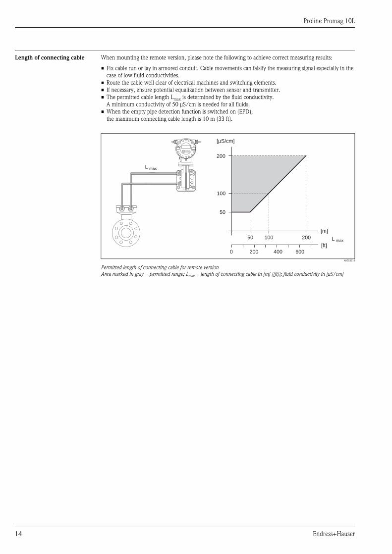
Length of connecting cable When mounting the remote version, please note the following to achieve correct measuring results:
• Fix cable run or lay in armored conduit. Cable movements can falsify the measuring signal especially in the
case of low fluid conductivities.
• Route the cable well clear of electrical machines and switching elements.
• If necessary, ensure potential equalization between sensor and transmitter.
• The permitted cable length Lmax is determined by the fluid conductivity.
A minimum conductivity of 50 μS/cm is needed for all fluids.
• When the empty pipe detection function is switched on (EPD),
the maximum connecting cable length is 10 m (33 ft).
A0003214
Permitted length of connecting cable for remote version
Area marked in gray = permitted range; Lmax = length of connecting cable in [m] ([ft]); fluid conductivity in [μS/cm]
L max
[ft]
200 6000 400
200
100
50 100 200
[m]
[µS/cm]
L max
50
Proline Promag 10L
Endress+Hauser 15
Operating conditions: Environment
Ambient temperature range Transmitter
• –20 to +60 °C (–4 to +140 °F)
Sensor
• Flange material carbon steel: –10 to +60 °C (14 to +140 °F)
• Flange material stainless steel (DN 300): –40 to +60 °C (–40 to +140 °F)
" Caution!
The permitted temperature range of the measuring tube lining may not be undershot or overshot
( ä 16, Section "Medium temperature range").
Please note the following points:
• Install the device in a shady location. Avoid direct sunlight, particularly in warm climatic regions.
• The transmitter must be mounted separate from the sensor if both the ambient and fluid temperatures are
high.
Storage temperature The storage temperature corresponds to the operating temperature range of the measuring transmitter and the
appropriate measuring sensors.
" Caution!
• The measuring device must be protected against direct sunlight during storage in order to avoid unacceptably
high surface temperatures.
• A storage location must be selected where moisture does not collect in the measuring device. This will help
prevent fungus and bacteria infestation which can damage the liner.
Degree of protection • Standard: IP 67 (NEMA 4X) for transmitter and sensor.
• Optional: IP 68 (NEMA 6P) for sensor for remote version (DN 300 only with stainless steel).
• For information regarding applications where the device is buried directly in the soil or is installed in a
flooded wastewater basin please contact your local Endress+Hauser Sales Center.
Shock and vibration resistance Acceleration up to 2 g following IEC 600 68-2-6
Electromagnetic compatibility
(EMC)
• As per IEC/EN 61326 as well as NAMUR Recommendation NE 21
• Emission: to limit value for industry EN 55011
Proline Promag 10L
16 Endress+Hauser
Operating conditions: Process
Medium temperature range • 0 to +80 °C (+32 to +176 °F) for hard rubber (DN 350 to 1200)
• –20 to +50 °C (–4 to +122 °F) for polyurethane (DN 50 to 1200)
• –20 to +90 °C (–4 to +194 °F) for PTFE (DN 50 to 300)
Conductivity The minimum conductivity is: 50 μS/cm
! Note!
In the remote version, the necessary minimum conductivity also depends on the cable length
( ä 14, Section "Length of connecting cable").
Medium pressure range
(nominal pressure)
• EN 1092-1 (DIN 2501)
– PN 6 (DN 350 to 1200)
– PN 10 (DN 50 to 1200)
– PN 16 (DN 50 to 150)
• EN 1092-1, lap joint flange, stampel plate
– PN 10 (DN 50 to 300)
• ANSI B 16.5
– Class 150 (2" to 24")
• AWWA
– Class D (32" to 48")
• AS2129
– Table E (350 to 1200)
• AS4087
– PN 16 (350 to 1200)
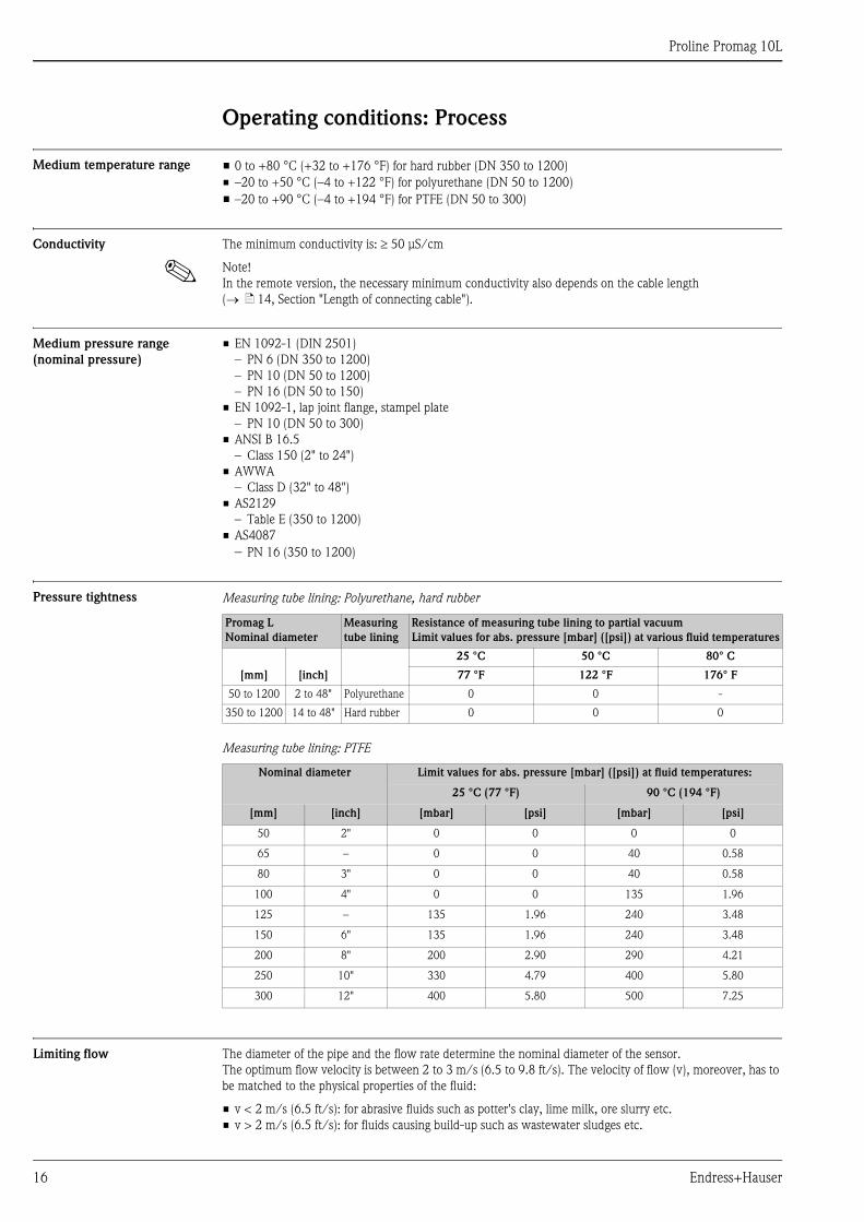
Pressure tightness Measuring tube lining: Polyurethane, hard rubber
Measuring tube lining: PTFE
Limiting flow The diameter of the pipe and the flow rate determine the nominal diameter of the sensor.
The optimum flow velocity is between 2 to 3 m/s (6.5 to 9.8 ft/s). The velocity of flow (v), moreover, has to
be matched to the physical properties of the fluid:
• v < 2 m/s (6.5 ft/s): for abrasive fluids such as potter's clay, lime milk, ore slurry etc.
• v > 2 m/s (6.5 ft/s): for fluids causing build-up such as wastewater sludges etc.
Promag L
Nominal diameter
Measuring
tube lining
Resistance of measuring tube lining to partial vacuum
Limit values for abs. pressure [mbar] ([psi]) at various fluid temperatures
[mm] [inch]
25 °C 50 °C 80° C
77 °F 122 °F 176° F
50 to 1200 2 to 48" Polyurethane 0 0 -
350 to 1200 14 to 48" Hard rubber 0 0 0
Nominal diameter Limit values for abs. pressure [mbar] ([psi]) at fluid temperatures:
25 °C (77 °F) 90 °C (194 °F)
[mm] [inch] [mbar] [psi] [mbar] [psi]
50 2" 0 0 0 0
65 – 0 0 40 0.58
80 3" 0 0 40 0.58
100 4" 0 0 135 1.96
125 – 135 1.96 240 3.48
150 6" 135 1.96 240 3.48
200 8" 200 2.90 290 4.21
250 10" 330 4.79 400 5.80
300 12" 400 5.80 500 7.25
Proline Promag 10L
Endress+Hauser 17
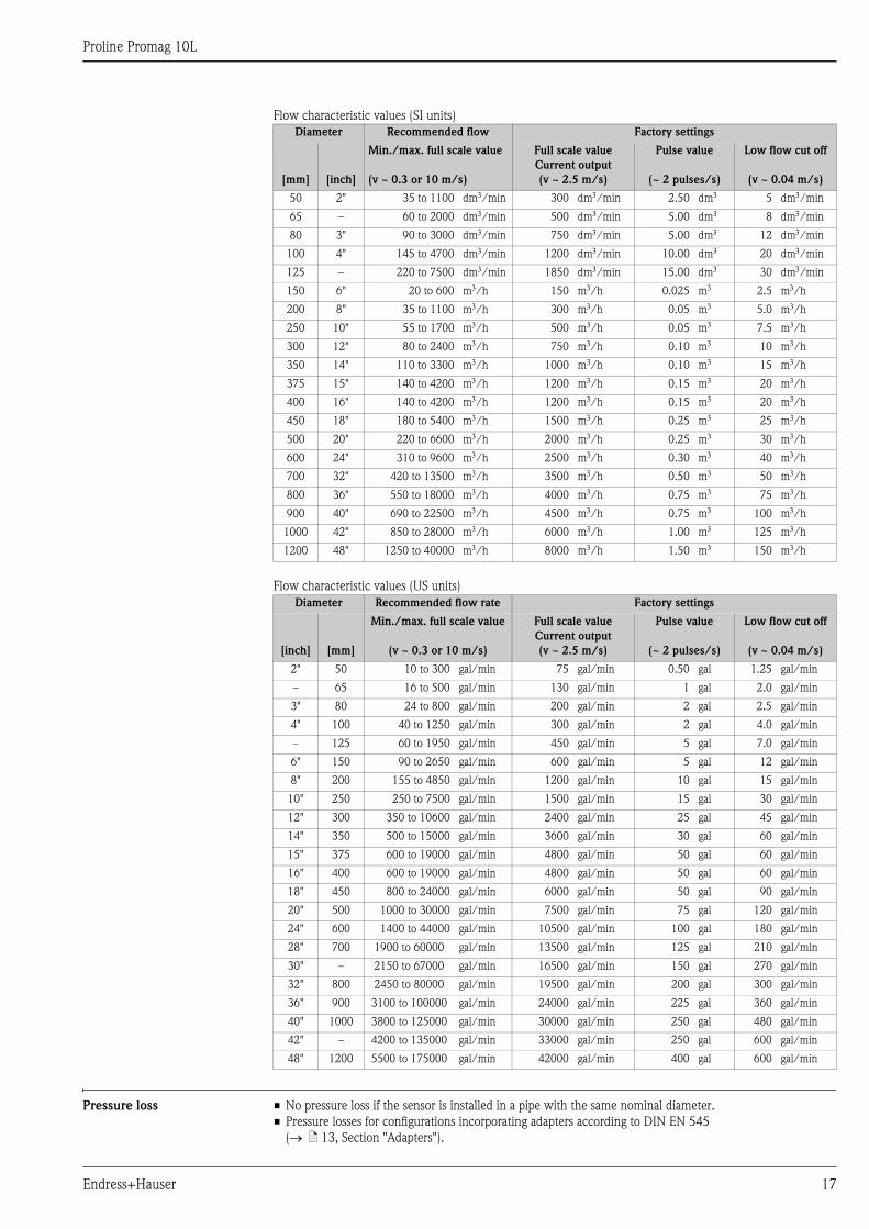
Flow characteristic values (SI units)
Flow characteristic values (US units)
Pressure loss • No pressure loss if the sensor is installed in a pipe with the same nominal diameter.
• Pressure losses for configurations incorporating adapters according to DIN EN 545
( ä 13, Section "Adapters").
Diameter Recommended flow Factory settings
[mm] [inch]
Min./max. full scale value
(v ~ 0.3 or 10 m/s)
Full scale value
Current output
(v ~ 2.5 m/s)
Pulse value
(~ 2 pulses/s)
Low flow cut off
(v ~ 0.04 m/s)
50 2" 35 to 1100 dm/min 300 dm/min 2.50 dm 5 dm/min
65 – 60 to 2000 dm/min 500 dm/min 5.00 dm 8 dm/min
80 3" 90 to 3000 dm/min 750 dm/min 5.00 dm 12 dm/min
100 4" 145 to 4700 dm/min 1200 dm/min 10.00 dm 20 dm/min
125 – 220 to 7500 dm/min 1850 dm/min 15.00 dm 30 dm/min
150 6" 20 to 600 m/h 150 m/h 0.025 m 2.5 m/h
200 8" 35 to 1100 m/h 300 m/h 0.05 m 5.0 m/h
250 10" 55 to 1700 m/h 500 m/h 0.05 m 7.5 m/h
300 12" 80 to 2400 m/h 750 m/h 0.10 m 10 m/h
350 14" 110 to 3300 m/h 1000 m/h 0.10 m 15 m/h
375 15" 140 to 4200 m/h 1200 m/h 0.15 m 20 m/h
400 16" 140 to 4200 m/h 1200 m/h 0.15 m 20 m/h
450 18" 180 to 5400 m/h 1500 m/h 0.25 m 25 m/h
500 20" 220 to 6600 m/h 2000 m/h 0.25 m 30 m/h
600 24" 310 to 9600 m/h 2500 m/h 0.30 m 40 m/h
700 32" 420 to 13500 m/h 3500 m/h 0.50 m 50 m/h
800 36" 550 to 18000 m/h 4000 m/h 0.75 m 75 m/h
900 40" 690 to 22500 m/h 4500 m/h 0.75 m 100 m/h
1000 42" 850 to 28000 m/h 6000 m/h 1.00 m 125 m/h
1200 48" 1250 to 40000 m/h 8000 m/h 1.50 m 150 m/h
Diameter Recommended flow rate Factory settings
[inch] [mm]
Min./max. full scale value
(v ~ 0.3 or 10 m/s)
Full scale value
Current output
(v ~ 2.5 m/s)
Pulse value
(~ 2 pulses/s)
Low flow cut off
(v ~ 0.04 m/s)
2" 50 10 to 300 gal/min 75 gal/min 0.50 gal 1.25 gal/min
– 65 16 to 500 gal/min 130 gal/min 1 gal 2.0 gal/min
3" 80 24 to 800 gal/min 200 gal/min 2 gal 2.5 gal/min
4" 100 40 to 1250 gal/min 300 gal/min 2 gal 4.0 gal/min
– 125 60 to 1950 gal/min 450 gal/min 5 gal 7.0 gal/min
6" 150 90 to 2650 gal/min 600 gal/min 5 gal 12 gal/min
8" 200 155 to 4850 gal/min 1200 gal/min 10 gal 15 gal/min
10" 250 250 to 7500 gal/min 1500 gal/min 15 gal 30 gal/min
12" 300 350 to 10600 gal/min 2400 gal/min 25 gal 45 gal/min
14" 350 500 to 15000 gal/min 3600 gal/min 30 gal 60 gal/min
15" 375 600 to 19000 gal/min 4800 gal/min 50 gal 60 gal/min
16" 400 600 to 19000 gal/min 4800 gal/min 50 gal 60 gal/min
18" 450 800 to 24000 gal/min 6000 gal/min 50 gal 90 gal/min
20" 500 1000 to 30000 gal/min 7500 gal/min 75 gal 120 gal/min
24" 600 1400 to 44000 gal/min 10500 gal/min 100 gal 180 gal/min
28" 700 1900 to 60000 gal/min 13500 gal/min 125 gal 210 gal/min
30" – 2150 to 67000 gal/min 16500 gal/min 150 gal 270 gal/min
32" 800 2450 to 80000 gal/min 19500 gal/min 200 gal 300 gal/min
36" 900 3100 to 100000 gal/min 24000 gal/min 225 gal 360 gal/min
40" 1000 3800 to 125000 gal/min 30000 gal/min 250 gal 480 gal/min
42" – 4200 to 135000 gal/min 33000 gal/min 250 gal 600 gal/min
48" 1200 5500 to 175000 gal/min 42000 gal/min 400 gal 600 gal/min
Proline Promag 10L
18 Endress+Hauser
Mechanical construction
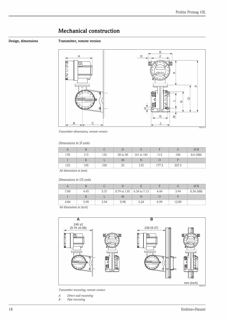
Design, dimensions Transmitter, remote version
A0010718
Transmitter dimensions, remote version
Dimensions in SI units
Dimensions in US units
A0010719
Transmitter mounting, remote version
A Direct wall mounting
B Pipe mounting
K
F
E
DA
H
L N
O
P
J
G
B C
M
ANSCHLUSSKLEMMEN - FIELD TERMINALS
A B C D E F G Ø H
178 113 135 20 to 30 161 to 181 113 100 8.6 (M8)
J K L M N O P
123 150 100 25 133 177.5 327.5
All dimensions in [mm]
A B C D E F G Ø H
7.00 4.45 5.31 0.79 to 1.81 6.34 to 7.13 4.44 3.94 0.34 (M8)
J K L M N O P
4.84 5.90 3.94 0.98 5.24 6.99 12.89
All dimensions in [inch]
248 ±2(9.76 ±0.08)
mm (inch)
238 (9.37)
A B
ANSCHLUSSKLEMMEN - FIELD TERMINALS ANSCHLUSSKLEMMEN - FIELD TERMINALS
Proline Promag 10L
Endress+Hauser 19
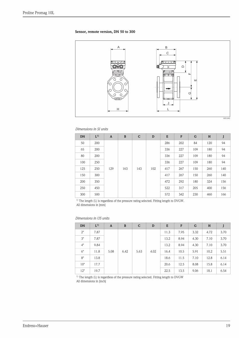
Sensor, remote version, DN 50 to 300
A0012462
Dimensions in SI units
Dimensions in US units
DN L1) A B C D E F G H J
50 200
129 163 143 102
286 202 84 120 94
65 200 336 227 109 180 94
80 200 336 227 109 180 94
100 250 336 227 109 180 94
125 250 417 267 150 260 140
150 300 417 267 150 260 140
200 350 472 292 180 324 156
250 450 522 317 205 400 156
300 500 572 342 230 460 166
1) The length (L) is regardless of the pressure rating selected. Fitting length to DVGW.
All dimensions in [mm]
DN L1) A B C D E F G H J
2" 7.87
5.08 6.42 5.63 4.02
11.3 7.95 3.32 4.72 3.70
3" 7.87 13.2 8.94 4.30 7.10 3.70
4" 9.84 13.2 8.94 4.30 7.10 3.70
6" 11.8 16.4 10.5 5.91 10.2 5.51
8" 13.8 18.6 11.5 7.10 12.8 6.14
10" 17.7 20.6 12.5 8.08 15.8 6.14
12" 19.7 22.5 13.5 9.06 18.1 6.54
1) The length (L) is regardless of the pressure rating selected. Fitting length to DVGW
All dimensions in [inch]
J
L
E
GF
H
B
C
A
D
Proline Promag 10L
20 Endress+Hauser
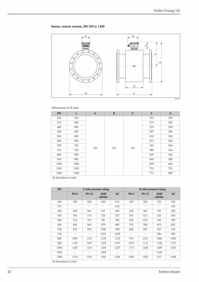
Sensor, remote version, DN 350 to 1200
A0014987
Dimensions in SI units
DN L A B C F G
350 550
129 163 102
353 290
375 600 379 290
400 600 379 290
450 600 407 290
500 600 432 290
600 600 473 290
700 700 543 424
750 750 580 454
800 800 599 500
900 900 649 580
1000 1000 699 660
1050 1050 735 755
1200 1200 713 828
All dimensions in [mm]
DN E with pressure rating H with pressure rating
PN 6 PN 10 ANSI
AWWA
AS PN 6 PN 10 ANSI
AWWA
AS
350 598 605 620 615 490 505 533 525
375 – – – 654 – – – 550
400 649 661 677 669 540 565 597 580
450 704 714 724 727 595 615 635 640
500 754 767 781 784 645 670 699 705
600 850 863 879 885 755 780 813 825
700 973 990 1006 998 860 895 927 910
750 – – 1072 1078 – – 984 995
800 1087 1107 1129 1129 975 1015 1060 1060
900 1187 1207 1233 1237 1075 1115 1168 1175
1000 1287 1314 1344 1227 1175 1230 1289 1255
1050 – – 1408 – – – 1346 –
1200 1516 1541 1569 1558 1405 1455 1511 1490
All dimensions in [mm]
L
G
E
F
H
A B
C
Proline Promag 10L
Endress+Hauser 21
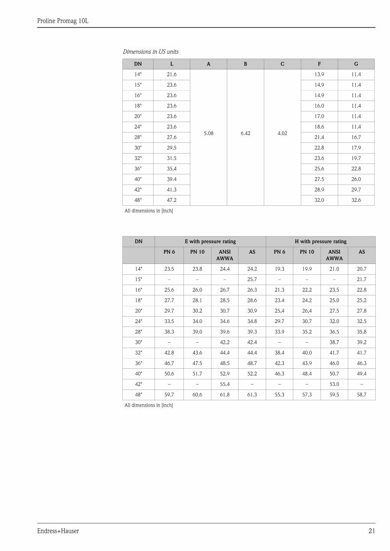
Dimensions in US units
DN L A B C F G
14" 21.6
5.08 6.42 4.02
13.9 11.4
15" 23.6 14.9 11.4
16" 23.6 14.9 11.4
18" 23.6 16.0 11.4
20" 23.6 17.0 11.4
24" 23.6 18.6 11.4
28" 27.6 21.4 16.7
30" 29.5 22.8 17.9
32" 31.5 23.6 19.7
36" 35.4 25.6 22.8
40" 39.4 27.5 26.0
42" 41.3 28.9 29.7
48" 47.2 32.0 32.6
All dimensions in [inch]
DN E with pressure rating H with pressure rating
PN 6 PN 10 ANSI
AWWA
AS PN 6 PN 10 ANSI
AWWA
AS
14" 23.5 23.8 24.4 24.2 19.3 19.9 21.0 20.7
15" – – – 25.7 – – – 21.7
16" 25.6 26.0 26.7 26.3 21.3 22.2 23.5 22.8
18" 27.7 28.1 28.5 28.6 23.4 24.2 25.0 25.2
20" 29.7 30.2 30.7 30.9 25,4 26,4 27.5 27.8
24" 33.5 34.0 34.6 34.8 29.7 30.7 32.0 32.5
28" 38.3 39.0 39.6 39.3 33.9 35.2 36.5 35.8
30" – – 42.2 42.4 – – 38.7 39.2
32" 42.8 43.6 44.4 44.4 38.4 40.0 41.7 41.7
36" 46.7 47.5 48.5 48.7 42.3 43.9 46.0 46.3
40" 50.6 51.7 52.9 52.2 46.3 48.4 50.7 49.4
42" – – 55.4 – – – 53.0 –
48" 59.7 60.6 61.8 61.3 55.3 57.3 59.5 58.7
All dimensions in [inch]
Proline Promag 10L
22 Endress+Hauser
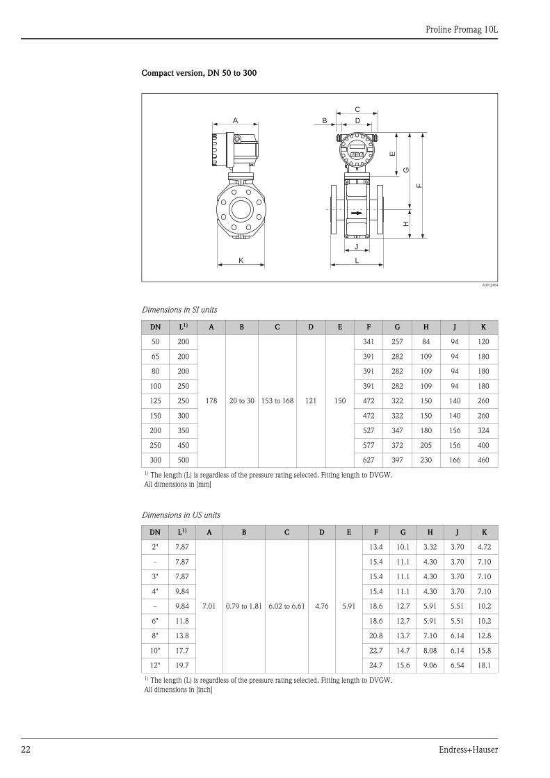
Compact version, DN 50 to 300
A0012464
Dimensions in SI units
Dimensions in US units
DN L1) A B C D E F G H J K
50 200
178 20 to 30 153 to 168 121 150
341 257 84 94 120
65 200 391 282 109 94 180
80 200 391 282 109 94 180
100 250 391 282 109 94 180
125 250 472 322 150 140 260
150 300 472 322 150 140 260
200 350 527 347 180 156 324
250 450 577 372 205 156 400
300 500 627 397 230 166 460
1) The length (L) is regardless of the pressure rating selected. Fitting length to DVGW.
All dimensions in [mm]
DN L1) A B C D E F G H J K
2" 7.87
7.01 0.79 to 1.81 6.02 to 6.61 4.76 5.91
13.4 10.1 3.32 3.70 4.72
– 7.87 15.4 11.1 4.30 3.70 7.10
3" 7.87 15.4 11.1 4.30 3.70 7.10
4" 9.84 15.4 11.1 4.30 3.70 7.10
– 9.84 18.6 12.7 5.91 5.51 10.2
6" 11.8 18.6 12.7 5.91 5.51 10.2
8" 13.8 20.8 13.7 7.10 6.14 12.8
10" 17.7 22.7 14.7 8.08 6.14 15.8
12" 19.7 24.7 15.6 9.06 6.54 18.1
1) The length (L) is regardless of the pressure rating selected. Fitting length to DVGW.
All dimensions in [inch]
K
J
L
F
HG
Esc
E- + E
A DB
C
Proline Promag 10L
Endress+Hauser 23
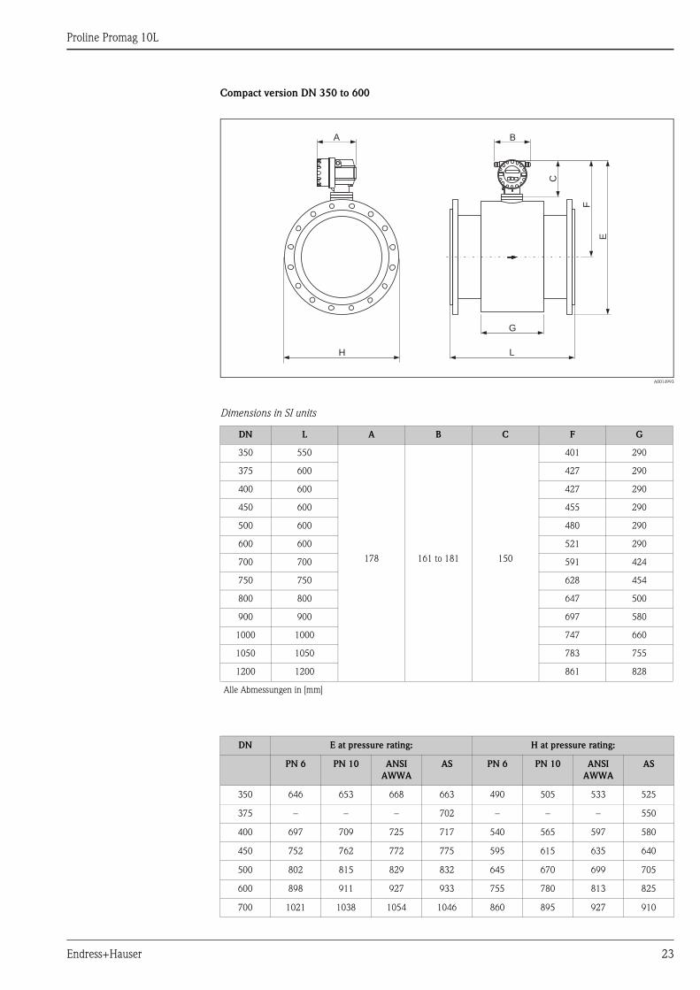
Compact version DN 350 to 600
A0014993
Dimensions in SI units
DN L A B C F G
350 550
178 161 to 181 150
401 290
375 600 427 290
400 600 427 290
450 600 455 290
500 600 480 290
600 600 521 290
700 700 591 424
750 750 628 454
800 800 647 500
900 900 697 580
1000 1000 747 660
1050 1050 783 755
1200 1200 861 828
Alle Abmessungen in [mm]
DN E at pressure rating: H at pressure rating:
PN 6 PN 10 ANSI
AWWA
AS PN 6 PN 10 ANSI
AWWA
AS
350 646 653 668 663 490 505 533 525
375 – – – 702 – – – 550
400 697 709 725 717 540 565 597 580
450 752 762 772 775 595 615 635 640
500 802 815 829 832 645 670 699 705
600 898 911 927 933 755 780 813 825
700 1021 1038 1054 1046 860 895 927 910
L
G
E
F
H
A B
C
Esc
E- +
Proline Promag 10L
24 Endress+Hauser
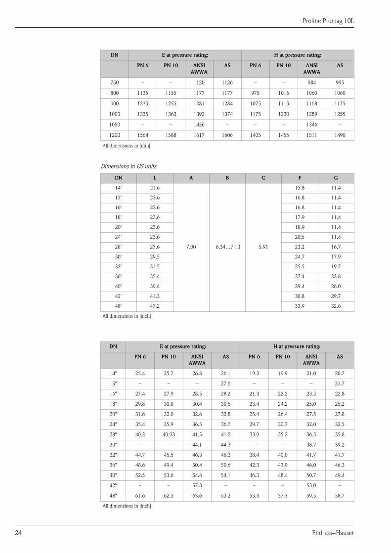
Dimensions in US units
750 – – 1120 1126 – – 984 995
800 1135 1155 1177 1177 975 1015 1060 1060
900 1235 1255 1281 1284 1075 1115 1168 1175
1000 1335 1362 1392 1374 1175 1230 1289 1255
1050 – – 1456 – – – 1346 –
1200 1564 1588 1617 1606 1405 1455 1511 1490
All dimensions in [mm]
DN L A B C F G
14" 21.6
7.00 6.34…7.13 5.91
15.8 11.4
15" 23.6 16.8 11.4
16" 23.6 16.8 11.4
18" 23.6 17.9 11.4
20" 23.6 18.9 11.4
24" 23.6 20.5 11.4
28" 27.6 23.2 16.7
30" 29.5 24.7 17.9
32" 31.5 25.5 19.7
36" 35.4 27.4 22.8
40" 39.4 29.4 26.0
42" 41.3 30.8 29.7
48" 47.2 33.9 32.6
All dimensions in [inch]
DN E at pressure rating: H at pressure rating:
PN 6 PN 10 ANSI
AWWA
AS PN 6 PN 10 ANSI
AWWA
AS
14" 25.4 25.7 26.3 26.1 19.3 19.9 21.0 20.7
15" – – – 27.6 – – – 21.7
16" 27.4 27.9 28.5 28.2 21.3 22.2 23.5 22.8
18" 29.8 30.0 30.4 30.5 23.4 24.2 25.0 25.2
20" 31.6 32.0 32.6 32.8 25.4 26.4 27.5 27.8
24" 35.4 35.9 36.5 36.7 29.7 30.7 32.0 32.5
28" 40.2 40.93 41.5 41.2 33.9 35.2 36.5 35.8
30" – – 44.1 44.3 – – 38.7 39.2
32" 44.7 45.5 46.3 46.3 38.4 40.0 41.7 41.7
36" 48.6 49.4 50.4 50.6 42.3 43.9 46.0 46.3
40" 52.5 53.6 54.8 54.1 46.3 48.4 50.7 49.4
42" – – 57.3 – – – 53.0 –
48" 61.6 62.5 63.6 63.2 55.3 57.3 59.5 58.7
All dimensions in [inch]
DN E at pressure rating: H at pressure rating:
PN 6 PN 10 ANSI
AWWA
AS PN 6 PN 10 ANSI
AWWA
AS

Proline Promag 10L
Endress+Hauser 25
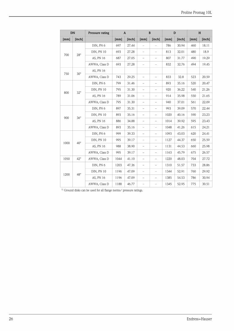
Ground disk
A0015442
Dimensions in SI and US units
DN Pressure rating A B D H
[mm] [inch] [mm] [inch] [mm] [inch] [mm] [inch] [mm] [inch]
50 2" 1) 52 2.05 101 3.98 115.5 4.55 108 4.25
65 2 ½" 1) 68 2.68 121 4.76 131.5 5.18 118 4.65
80 3" 1) 80 3.15 131 5.16 154.5 6.08 135 5.31
100 4" 1) 104 4.09 156 6.14 186.5 7.34 153 6.02
125 5" 1) 130 5.12 187 7.36 206.5 8.13 160 6.30
150 6" 1) 158 6.22 217 8.54 256 10.08 184 7.24
200 8" 1) 206 8.11 267 10.51 288 11.34 205 8.07
250 10" 1) 260 10.24 328 12.91 359 14.13 240 9.45
300 12" 1) 312 12.28 375 14.76 413 16.26 273 10.75
350 14"
DIN, PN 6
343 13.50
433 16.54
479 18.86 365 14.37DIN, PN 10
420 17.05ANSI, Cl.150
400 16"
DIN, PN 6
393 15.47
470 18.50
542 21.34 395 15.55DIN, PN 10
480 18.90ANSI, Cl.150
450 18"
DIN, PN 6
439 17.28
525 20.67
583 22.95 417 16.42DIN, PN 10
538 21.18ANSI, Cl.150
500 20"
DIN, PN 6
493 19.41
575 23.31
650 25.59 460 18.11DIN, PN 10
592 22.64ANSI, Cl.150
600 24"
DIN, PN 6
593 23.35
676 27.28
766 30.16 522 20.55DIN, PN 10
693 26.61ANSI, Cl.150
H
H
ØB
ØBØA
ØDØD
ØA
H
ØDØA
DN � 300 (12")
mm (inch)
DN 350 …DN 600 (24")(14")
Ø 6.5 (0.26)Ø 9 (0.35)
t = 2 (0.08)t = 2 (0.08)
Ø 6.4 (0.25)
DN 700 (28")�
t = 2 (0.08)
Proline Promag 10L
26 Endress+Hauser
700 28"
DIN, PN 6 697 27.44 – – 786 30.94 460 18.11
DIN, PN 10 693 27.28 – – 813 32.01 480 18.9
AS, PN 16 687 27.05 – – 807 31.77 490 19.29
AWWA, Class D 693 27.28 – – 832 32.76 494 19.45
750 30"AS, PN 16
AWWA, Class D 743 29.25 – – 833 32.8 523 20.59
800 32"
DIN, PN 6 799 31.46 – – 893 35.16 520 20.47
DIN, PN 10 795 31.30 – – 920 36.22 540 21.26
AS, PN 16 789 31.06 – – 914 35.98 550 21.65
AWWA, Class D 795 31.30 – – 940 37.01 561 22.09
900 36"
DIN, PN 6 897 35.31 – – 993 39.09 570 22.44
DIN, PN 10 893 35.16 – – 1020 40.16 590 23.23
AS, PN 16 886 34.88 – – 1014 39.92 595 23.43
AWWA, Class D 893 35.16 – – 1048 41.26 615 24.21
1000 40"
DIN, PN 6 999 39.33 – – 1093 43.03 620 24.41
DIN, PN 10 995 39.17 – – 1127 44.37 650 25.59
AS, PN 16 988 38.90 – – 1131 44.53 660 25.98
AWWA, Class D 995 39.17 – – 1163 45.79 675 26.57
1050 42" AWWA, Class D 1044 41.10 – – 1220 48.03 704 27.72
1200 48"
DIN, PN 6 1203 47.36 – – 1310 51.57 733 28.86
DIN, PN 10 1196 47.09 – – 1344 52.91 760 29.92
AS, PN 16 1196 47.09 – – 1385 54.53 786 30.94
AWWA, Class D 1188 46.77 – – 1345 52.95 775 30.51
1) Ground disks can be used for all flange norms/ pressure ratings.
DN Pressure rating A B D H
[mm] [inch] [mm] [inch] [mm] [inch] [mm] [inch] [mm] [inch]

Proline Promag 10L
Endress+Hauser 27
Weight SI units
Compact version (lap joint flanges / welded flanges DN >350)
Weight data in kg
Nominal diameter Compact version
(including transmitter)
[mm] [inch] EN (DIN) EN (DIN) ANSI / AWWA AS
50 2"
PN
16
9.0
PN
6
–
AN
SI
/ C
lass
15
0
9.00
PN
16
. T
abel
le E
–
65 2 ½" 10.4 – – –
80 3" 12.4 – 12.4 –
100 4" 14.4 – 14.4 –
125 5" 19.9 – – –
150 6" 23.9 – 23.9 –
200 8"
PN
10
43.4 – 43.4 –
250 10" 63.4 – 63.4 –
300 12" 68.4 – 68.4 –
350 14" 88.4 77.4 137.4 99.4
375 15" – – – 105.4
400 16" 104. 4 89.4 168.4 120.4
450 18" 112.4 99.4 191.4 133.4/143.4*
500 20" 132.4 114.4 228.4 182.4
600 24" 155. 4 155.4 302.4 260.4
700 28" 246. 4 198.4
AW
WA
/ C
lass
D
275.4 339.4
750 30" – – 327.4 439.4
800 32" 320.4 246.4 394.4 499.4
900 36" 400.4 314.4 480.4 696.4
1000 40" 473.4 364.4 599.4 767.4
– 42" – – 682,4 –
1200 48" 722.4 535.4 912.4 1225.4
Transmitter Promag (compact version): 1.8 kg
(Weight data valid without packaging material)
*DN450 AS Tab E
Proline Promag 10L
28 Endress+Hauser
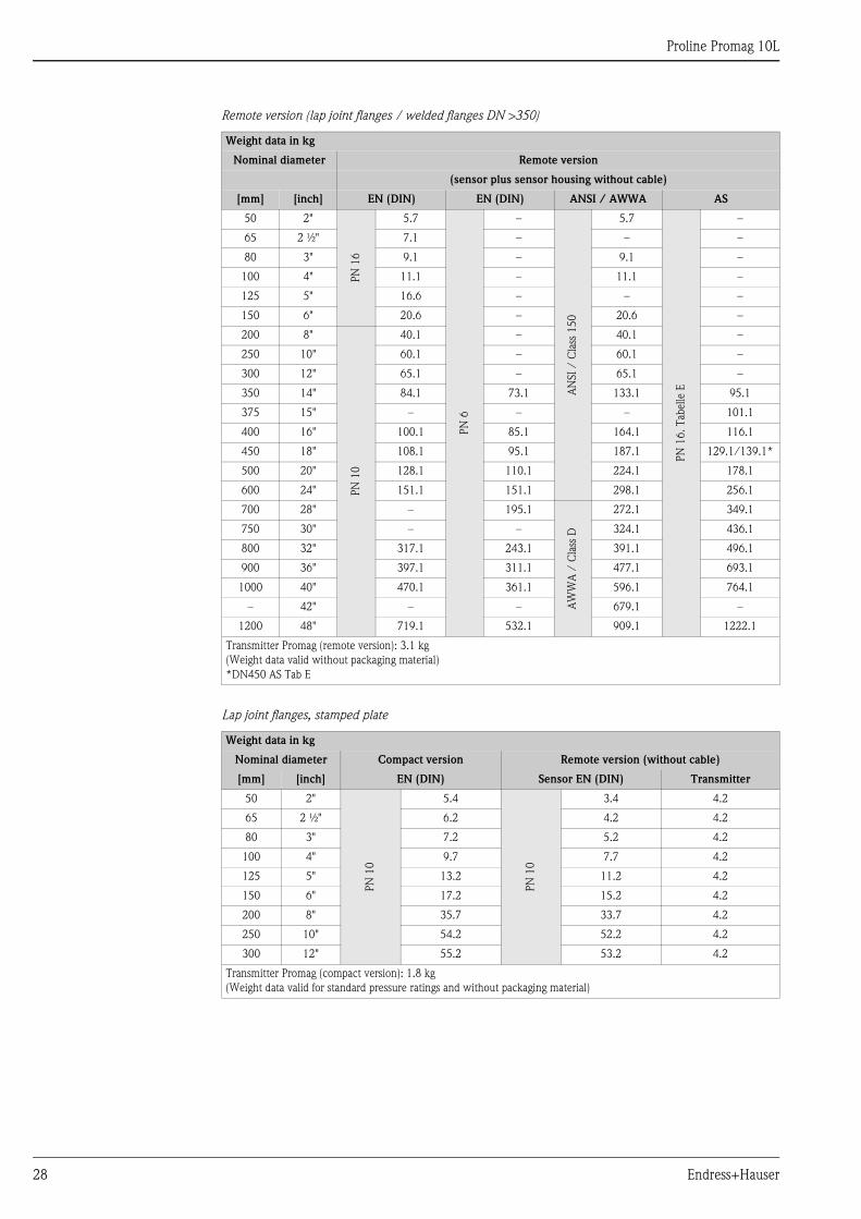
Remote version (lap joint flanges / welded flanges DN >350)
Lap joint flanges, stamped plate
Weight data in kg
Nominal diameter Remote version
(sensor plus sensor housing without cable)
[mm] [inch] EN (DIN) EN (DIN) ANSI / AWWA AS
50 2"
PN
16
5.7
PN
6
–
AN
SI
/ C
lass
15
0
5.7
PN
16
. T
abel
le E
–
65 2 ½" 7.1 – – –
80 3" 9.1 – 9.1 –
100 4" 11.1 – 11.1 –
125 5" 16.6 – – –
150 6" 20.6 – 20.6 –
200 8"
PN
10
40.1 – 40.1 –
250 10" 60.1 – 60.1 –
300 12" 65.1 – 65.1 –
350 14" 84.1 73.1 133.1 95.1
375 15" – – – 101.1
400 16" 100.1 85.1 164.1 116.1
450 18" 108.1 95.1 187.1 129.1/139.1*
500 20" 128.1 110.1 224.1 178.1
600 24" 151.1 151.1 298.1 256.1
700 28" – 195.1
AW
WA
/ C
lass
D
272.1 349.1
750 30" – – 324.1 436.1
800 32" 317.1 243.1 391.1 496.1
900 36" 397.1 311.1 477.1 693.1
1000 40" 470.1 361.1 596.1 764.1
– 42" – – 679.1 –
1200 48" 719.1 532.1 909.1 1222.1
Transmitter Promag (remote version): 3.1 kg
(Weight data valid without packaging material)
*DN450 AS Tab E
Weight data in kg
Nominal diameter Compact version Remote version (without cable)
[mm] [inch] EN (DIN) Sensor EN (DIN) Transmitter
50 2"
PN
10
5.4
PN
10
3.4 4.2
65 2 ½" 6.2 4.2 4.2
80 3" 7.2 5.2 4.2
100 4" 9.7 7.7 4.2
125 5" 13.2 11.2 4.2
150 6" 17.2 15.2 4.2
200 8" 35.7 33.7 4.2
250 10" 54.2 52.2 4.2
300 12" 55.2 53.2 4.2
Transmitter Promag (compact version): 1.8 kg
(Weight data valid for standard pressure ratings and without packaging material)
Proline Promag 10L
Endress+Hauser 29
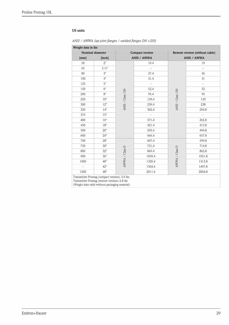
US units
ANSI / AWWA (lap joint flanges / welded flanges DN >350)
Weight data in lbs
Nominal diameter Compact version Remote version (without cable)
[mm] [inch] ANSI / AWWA ANSI / AWWA
50 2"
AN
SI
/ C
lass
15
0
19.4
AN
SI
/ C
lass
15
0
19
65 2 ½" – –
80 3" 27.4 26
100 4" 31.4 31
125 5" – –
150 6" 52.4 52
200 8" 95.4 95
250 10" 139.4 139
300 12" 239.4 238
350 14" 302.4 294.8
375 15" – –
400 16" 371.4 262.8
450 18" 421.4 413.8
500 20" 503.4 494.8
600 24" 666.4 657.8
700 28"
AW
WA
/ C
lass
D
607.4
AW
WA
/ C
lass
D
599.8
750 30" 721.4 714.8
800 32" 869.4 862.8
900 36" 1059.4 1051.8
1000 40" 1320.4 1313.8
– 42" 1504.4 1497.8
1200 48" 2011.4 2004.8
Transmitter Promag (compact version): 3.9 lbs
Transmitter Promag (remote version): 6.8 lbs
(Weight data valid without packaging material)
Proline Promag 10L
30 Endress+Hauser
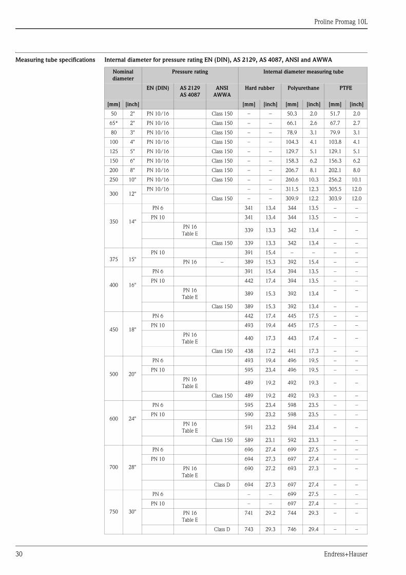
Measuring tube specifications Internal diameter for pressure rating EN (DIN), AS 2129, AS 4087, ANSI and AWWA
Nominal
diameter
Pressure rating Internal diameter measuring tube
EN (DIN) AS 2129
AS 4087
ANSI
AWWA
Hard rubber Polyurethane PTFE
[mm] [inch] [mm] [inch] [mm] [inch] [mm] [inch]
50 2" PN 10/16 Class 150 – – 50.3 2.0 51.7 2.0
65* 2" PN 10/16 Class 150 – – 66.1 2.6 67.7 2.7
80 3" PN 10/16 Class 150 – – 78.9 3.1 79.9 3.1
100 4" PN 10/16 Class 150 – – 104.3 4.1 103.8 4.1
125 5" PN 10/16 Class 150 – – 129.7 5.1 129.1 5.1
150 6" PN 10/16 Class 150 – – 158.3 6.2 156.3 6.2
200 8" PN 10/16 Class 150 – – 206.7 8.1 202.1 8.0
250 10" PN 10/16 Class 150 – – 260.6 10.3 256.2 10.1
300 12"PN 10/16 – – 311.5 12.3 305.5 12.0
Class 150 – – 309.9 12.2 303.9 12.0
350 14"
PN 6 341 13.4 344 13.5 – –
PN 10 341 13.4 344 13.5 – –
PN 16
Table E339 13.3 342 13.4 – –
Class 150 339 13.3 342 13.4 – –
375 15"
PN 10 391 15.4 – – – –
PN 16 – 389 15.3 392 15.4 – –
400 16"
PN 6 391 15.4 394 13.5 – –
PN 10 442 17.4 394 13.5 – –
PN 16
Table E389 15.3 392 13.4
– –
Class 150 389 15.3 392 13.4 – –
450 18"
PN 6 442 17.4 445 17.5 – –
PN 10 493 19.4 445 17.5 – –
PN 16
Table E440 17.3 443 17.4 – –
Class 150 438 17.2 441 17.3 – –
500 20"
PN 6 493 19.4 496 19.5 – –
PN 10 595 23.4 496 19.5 – –
PN 16
Table E489 19.2 492 19.3 – –
Class 150 489 19.2 492 19.3 – –
600 24"
PN 6 595 23.4 598 23.5 – –
PN 10 590 23.2 598 23.5 – –
PN 16
Table E591 23.2 594 23.4 – –
Class 150 589 23.1 592 23.3 – –
700 28"
PN 6 696 27.4 699 27.5 – –
PN 10 694 27.3 697 27.4 – –
PN 16
Table E
690 27.2 693 27.3 – –
Class D 694 27.3 697 27.4 – –
750 30"
PN 6 – – 699 27.5 – –
PN 10 – – 697 27.4 – –
PN 16
Table E
741 29.2 744 29.3 – –
Class D 743 29.3 746 29.4 – –
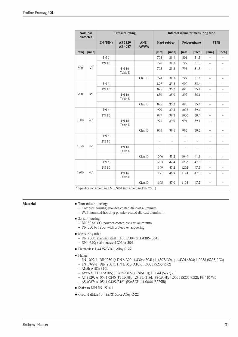
Proline Promag 10L
Endress+Hauser 31
Material • Transmitter housing:
– Compact housing: powder-coated die-cast aluminum
– Wall-mounted housing: powder-coated die-cast aluminum
• Sensor housing
– DN 50 to 300: powder-coated die-cast aluminum
– DN 350 to 1200: with protective lacquering
• Measuring tube:
– DN 300; stainless steel 1.4301/304 or 1.4306/304L
– DN 350; stainless steel 202 or 304
• Electrodes: 1.4435/304L, Alloy C-22
• Flange
– EN 1092-1 (DIN 2501): DN 300: 1.4306/304L; 1.4307/304L; 1.4301/304; 1.0038 (S235JRG2)
– EN 1092-1 (DIN 2501): DN 350: A105; 1.0038 (S235JRG2)
– ANSI: A105; 316L
– AWWA: A181/A105; 1.0425/316L (P265GH); 1.0044 (S275JR)
– AS 2129: A105; 1.0345 (P235GH); 1.0425/316L (P265GH); 1.0038 (S235JRG2); FE 410 WB
– AS 4087: A105; 1.0425/316L (P265GH); 1.0044 (S275JR)
• Seals: to DIN EN 1514-1
• Ground disks: 1.4435/316L or Alloy C-22
800 32"
PN 6 798 31.4 801 31.5 – –
PN 10 796 31.3 799 31.5 – –
PN 16
Table E
792 31.2 795 31.3 – –
Class D 794 31.3 797 31.4 – –
900 36"
PN 6 897 35.3 900 35.4 – –
PN 10 895 35.2 898 35.4 – –
PN 16
Table E
889 35.0 892 35.1 – –
Class D 895 35.2 898 35.4 – –
1000 40"
PN 6 999 39.3 1002 39.4 – –
PN 10 997 39.3 1000 39.4 – –
PN 16
Table E
991 39.0 994 39.1 – –
Class D 995 39.1 998 39.3 – –
1050 42"
PN 6 – – – – – –
PN 10 – – – – – –
PN 16
Table E
– – – – – –
Class D 1046 41.2 1049 41.3 – –
1200 48"
PN 6 1203 47.4 1206 47.5 – –
PN 10 1199 47.2 1202 47.3 – –
PN 16
Table E
1191 46.9 1194 47.0 – –
Class D 1195 47.0 1198 47.2 – –
* Specification according EN 1092-1 (not according DIN 2501)
Nominal
diameter
Pressure rating Internal diameter measuring tube
EN (DIN) AS 2129
AS 4087
ANSI
AWWA
Hard rubber Polyurethane PTFE
[mm] [inch] [mm] [inch] [mm] [inch] [mm] [inch]
Proline Promag 10L
32 Endress+Hauser
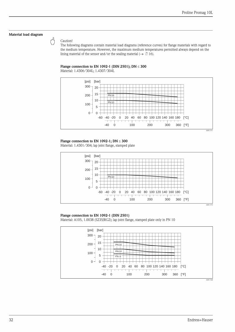
Material load diagram
" Caution!
The following diagrams contain material load diagrams (reference curves) for flange materials with regard to
the medium temperature. However, the maximum medium temperatures permitted always depend on the
lining material of the sensor and/or the sealing material ( ä 16).
Flange connection to EN 1092-1 (DIN 2501); DN 300
Material: 1.4306/304L; 1.4307/304L
A0011571
Flange connection to EN 1092-1; DN 300
Material: 1.4301/304; lap joint flange, stamped plate
A0011573
Flange connection to EN 1092-1 (DIN 2501)
Material: A105, 1.0038 (S235JRG2); lap joint flange, stamped plate only in PN 10
A0011568
PN16
PN10
0
5
10
15
20
[bar][psi]
-60 -40 -20 0 20 40 60 80 100 120 140 160 180 [°C]
360 [°F]0-40 100 200 300
200
100
300
0
PN10
0
5
10
15
20
[bar][psi]
-60 -40 -20 0 20 40 60 80 100 120 140 160 180 [°C]
360 [°F]0-40 100 200 300
200
100
300
0
PN 16
PN 10
0
5
10
15
20
[bar][psi]
-40 -20 0 20 40 60 80 100 120 140 160 180 [°C]
3600-40 100 200 300
200
100
300
0
[°F]
PN 6
Proline Promag 10L
Endress+Hauser 33
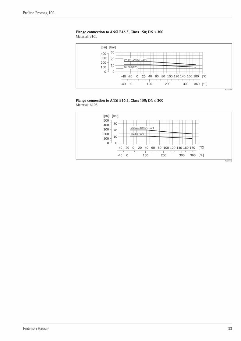
Flange connection to ANSI B16.5, Class 150; DN 300
Material: 316L
A0011580
Flange connection to ANSI B16.5, Class 150; DN 300
Material: A105
A0011572
0
10
20
30
[bar][psi]
-40 -20 0 20 40 60 80 100 120 140 160 180 [°C]
360 [°F]0-40 100 200 300
200
100
400
300
0
DN50…250 (2"…10")
DN300 (12")
-40 [°C]-20 0 20 40 60 80 100 120 140 160 180
0-40 100 200 300 [°F]
0
10
20
30
[bar][psi]
200
100
400
300
500
0
360
DN50…250 (2"…10")
DN300 (12")
Proline Promag 10L
34 Endress+Hauser
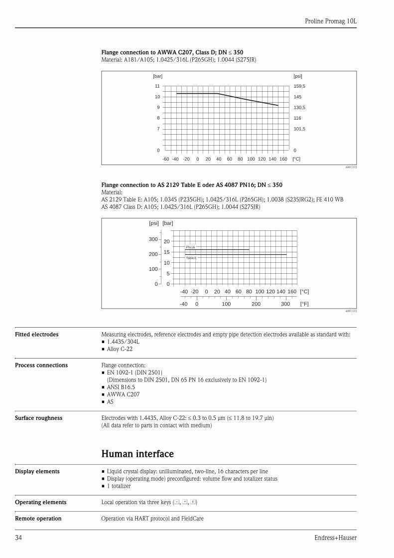
Flange connection to AWWA C207, Class D; DN 350
Material: A181/A105; 1.0425/316L (P265GH); 1.0044 (S275JR)
A0011572
Flange connection to AS 2129 Table E oder AS 4087 PN16; DN 350
Material:
AS 2129 Table E: A105; 1.0345 (P235GH); 1.0425/316L (P265GH); 1.0038 (S235JRG2); FE 410 WB
AS 4087 Class D: A105; 1.0425/316L (P265GH); 1.0044 (S275JR)
A0011572
Fitted electrodes Measuring electrodes, reference electrodes and empty pipe detection electrodes available as standard with:
• 1.4435/304L
• Alloy C-22
Process connections Flange connection:
• EN 1092-1 (DIN 2501)
(Dimensions to DIN 2501, DN 65 PN 16 exclusively to EN 1092-1)
• ANSI B16.5
• AWWA C207
• AS
Surface roughness Electrodes with 1.4435, Alloy C-22: 0.3 to 0.5 μm (11.8 to 19.7 μin)
(All data refer to parts in contact with medium)
Human interface
Display elements • Liquid crystal display: unilluminated, two-line, 16 characters per line
• Display (operating mode) preconfigured: volume flow and totalizer status
• 1 totalizer
Operating elements Local operation via three keys (S, O, F)
Remote operation Operation via HART protocol and FieldCare
0
7
8
9
10
11
[bar]
0
101,5
116
130,5
145
159,5
[psi]
-60 -40 -20 0 20 40 60 80 100 120 140 160 [°C]
-40 -20 0 20 40 60 80 100 120 140 160 [°C]
0
10
5
20
15
[bar]
0-40 100 200 300 [°F]
[psi]
200
100
300
0
TableE
PN16
Proline Promag 10L
Endress+Hauser 35
Certificates and approvals
CE mark The measuring system is in conformity with the statutory requirements of the EC Directives.
Endress+Hauser confirms successful testing of the device by affixing to it the CE mark.
C-tick mark The measuring system meets the EMC requirements of the
"Australian Communication and Media Authority (ACMA)".
Drinking water approval • WRAS BS 6920
• ACS
• NSF 61
• KTW/W270
Other standards and
guidelines
• EN 60529
Degrees of protection by housing (IP code).
• EN 61010
Protection Measures for Electrical Equipment for Measurement, Control, Regulation and Laboratory
Procedures.
• IEC/EN 61326
"Emission in accordance with requirements for Class A".
Electromagnetic compatibility (EMC requirements).
• ANSI/ISA-S82.01
Safety Standard for Electrical and Electronic Test, Measuring, Controlling and related
Equipment - General Requirements. Pollution degree 2, Installation Category II.
• CAN/CSA-C22.2 No. 1010.1-92
Safety requirements for Electrical Equipment for Measurement and Control and Laboratory Use.
Pollution degree 2, Installation Category II
Ordering informationYour Endress+Hauser service organization can provide detailed ordering information and information on the
order codes on request.
AccessoriesVarious accessories, which can be ordered separately from Endress+Hauser, are available for the transmitter
and the sensor. Your Endress+Hauser service organization can provide detailed information on the order codes
in question.
Documentation • Flow measurement (FA005D/06)
• Operating Instructions Promag 10 (BA00082D/06)
Registered trademarksKALREZ® and VITON®
Registered trademarks of E.I. Du Pont de Nemours & Co., Wilmington, USA
TRI-CLAMP®
Registered trademark of Ladish & Co., Inc., Kenosha, USA
HART®
Registered trademark of the HART Communication Foundation, Austin, USA
FieldCare®, Fieldcheck®, Field Xpert™, Applicator®
Registered or registration-pending trademarks of Endress+Hauser Flowtec AG, Reinach, CH
Instruments International
Endress+HauserInstruments International AGKaegenstrasse 24153 ReinachSwitzerland
Tel.+41 61 715 81 00Fax+41 61 715 25 [email protected]
TI00100D/06/EN/14.11
71136637
FM+SGML6.0 ProMoDo