Production of advanced biobased hydrogen enriched methane...
29
Production of advanced biobased hydrogen enriched methane from waste glycerol in a two - stage continuous system A . S. Dounavis 1,2 , Ι. Νtaikou 1 , G. Lyberatos 1,3 1 Institute of Chemical Engineering and Scienses (ICEHT/FORTH) 2 Department of Chemical Engineering, University of Patras 3 School of Chemical Engineering, National Technical University of Athens IWWATV Conference, President Hotel, Athens 21/05/2015
Transcript of Production of advanced biobased hydrogen enriched methane...
Production of advanced biobased hydrogen enriched
methane from waste glycerol in a two-stage continuous
system
A. S. Dounavis1,2, Ι. Νtaikou1, G. Lyberatos1,3
1 Institute of Chemical Engineering and Scienses (ICEHT/FORTH)
2 Department of Chemical Engineering, University of Patras
3 School of Chemical Engineering, National Technical University of Athens
IWWATV Conference, President Hotel, Athens 21/05/2015
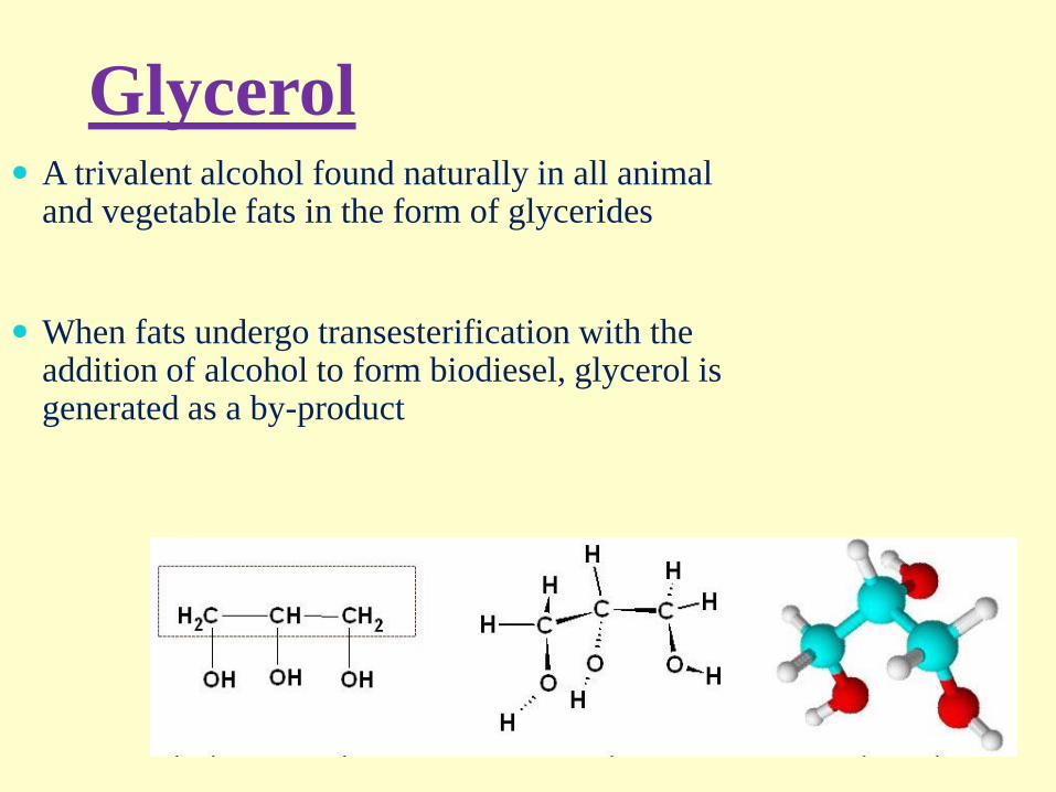
Glycerol A trivalent alcohol found naturally in all animal
and vegetable fats in the form of glycerides
When fats undergo transesterification with the addition of alcohol to form biodiesel, glycerol is generated as a by-product
…In the recent years
The rapid growth of biodiesel industry has generated
a significant amount of crude glycerol as a by-product
Used in:
Industries such as food, cosmetics and pharmaceutical
PROBLEM:
• Large availability
• Low market price
Proposed Solution:
Use as a carbon source for the production of bio-fuels or
other high added value bio-products via biological
processes
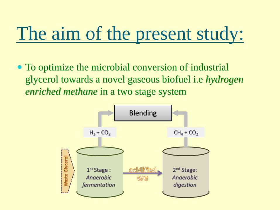
To optimize the microbial conversion of industrial
glycerol towards a novel gaseous biofuel i.e hydrogen
enriched methane in a two stage system
The aim of the present study:
1st Stage :Anaerobic
fermentation
2nd Stage: Anaerobic digestion
Blending
H2 + CO2 CH4 + CO2
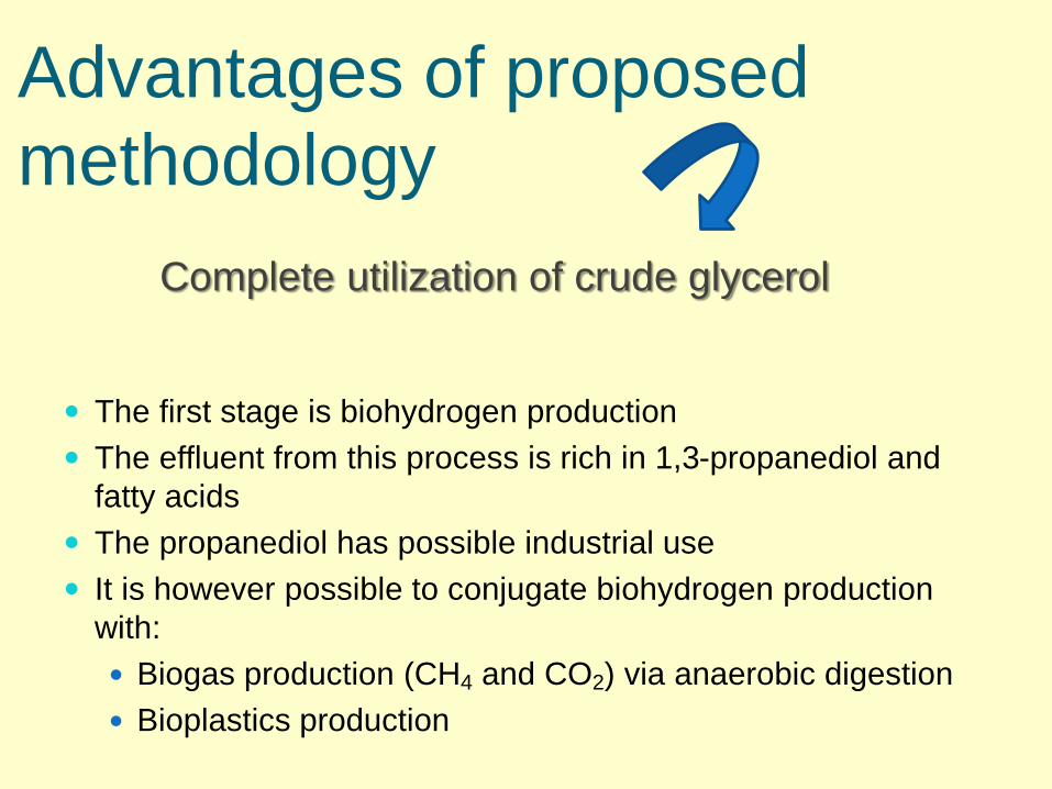
Advantages of proposed
methodology
The first stage is biohydrogen production
The effluent from this process is rich in 1,3-propanediol and
fatty acids
The propanediol has possible industrial use
It is however possible to conjugate biohydrogen production
with:
Biogas production (CH4 and CO2) via anaerobic digestion
Bioplastics production
Complete utilization of crude glycerol
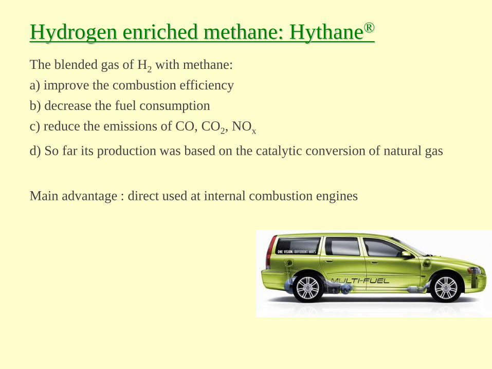
Hydrogen enriched methane: Hythane®
The blended gas of H2 with methane:
a) improve the combustion efficiency
b) decrease the fuel consumption
c) reduce the emissions of CO, CO2, NOx
d) So far its production was based on the catalytic conversion of natural gas
Main advantage : direct used at internal combustion engines
Hythane
The challenge of
a) producing low-cost
b) sustainable
c) more environmentally friendly biofuel than methane alone
d) high hydrogen-enriched methane
To attain its potential market position
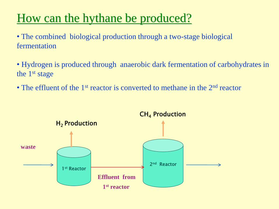
How can the hythane be produced?
• The combined biological production through a two-stage biological
fermentation
• Hydrogen is produced through anaerobic dark fermentation of carbohydrates in
the 1st stage
• The effluent of the 1st reactor is converted to methane in the 2nd reactor
1st Reactor
H2 Production
2nd Reactor
CH4 Production
Effluent from
1st reactor
waste
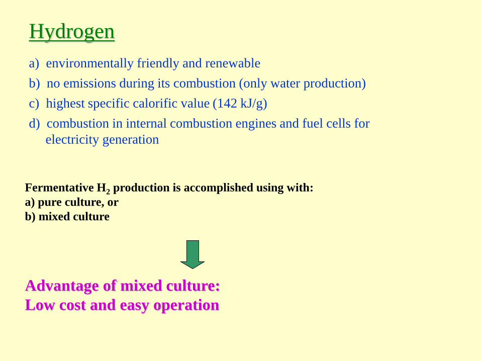
Hydrogen
c) highest specific calorific value (142 kJ/g)
b) no emissions during its combustion (only water production)
d) combustion in internal combustion engines and fuel cells for
electricity generation
a) environmentally friendly and renewable
Fermentative H2 production is accomplished using with:
a) pure culture, or
b) mixed culture
Advantage of mixed culture:
Low cost and easy operation
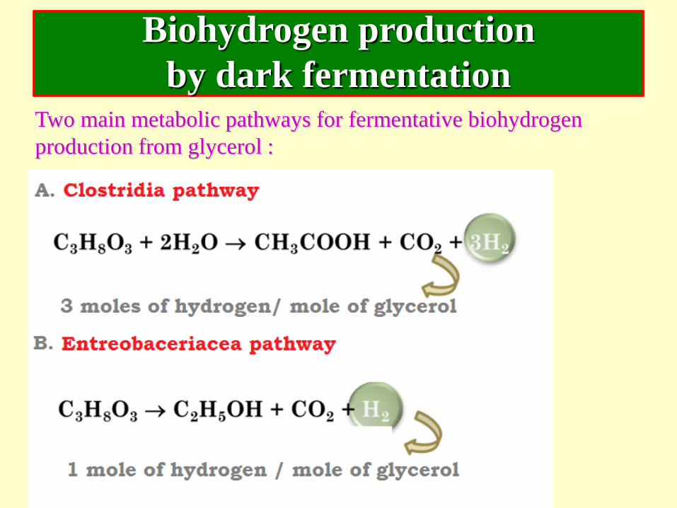
Biohydrogen production
by dark fermentationTwo main metabolic pathways for fermentative biohydrogen
production from glycerol :
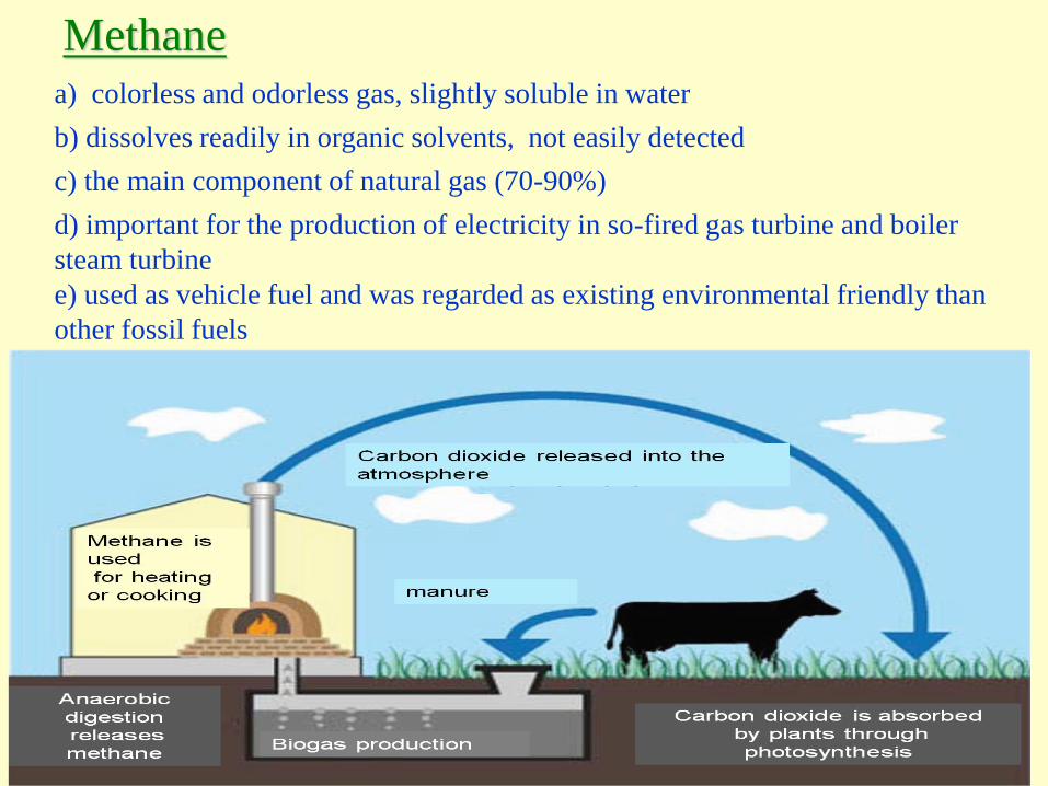
Methane
c) the main component of natural gas (70-90%)
b) dissolves readily in organic solvents, not easily detected
d) important for the production of electricity in so-fired gas turbine and boiler
steam turbine
a) colorless and odorless gas, slightly soluble in water
e) used as vehicle fuel and was regarded as existing environmental friendly than
other fossil fuels
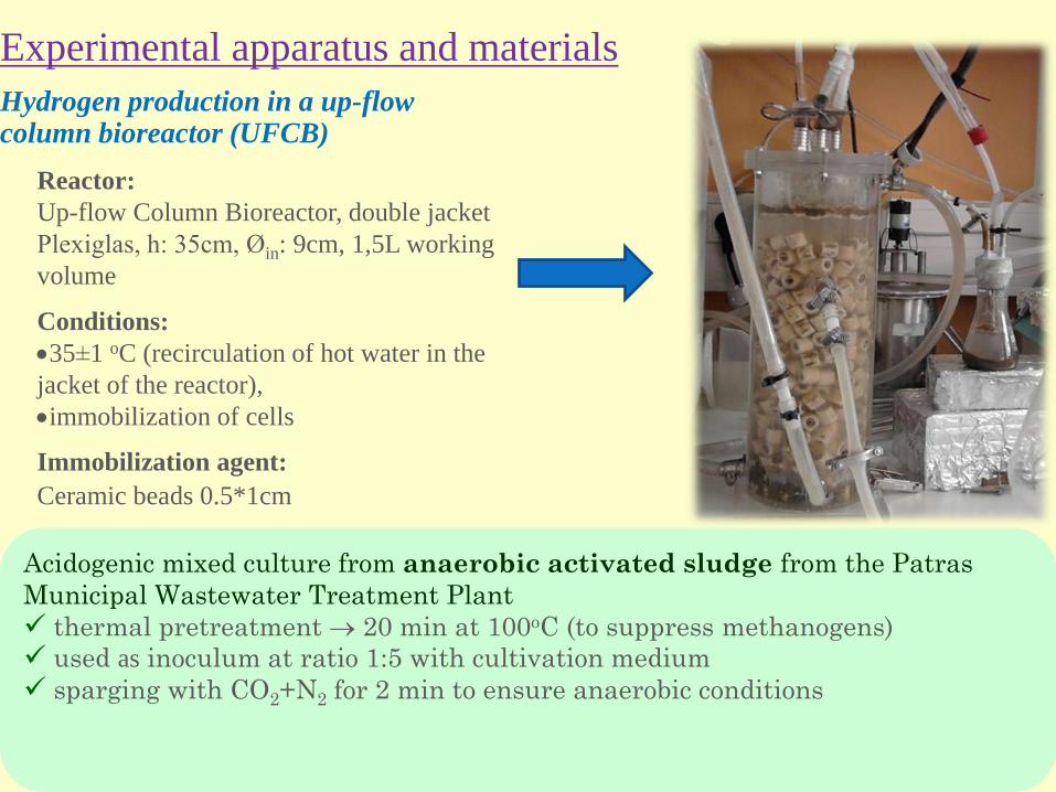
Experimental apparatus and materials
Reactor:
Up-flow Column Bioreactor, double jacket
Plexiglas, h: 35cm, Øin: 9cm, 1,5L working
volume
Acidogenic mixed culture from anaerobic activated sludge from the Patras
Municipal Wastewater Treatment Plant
thermal pretreatment 20 min at 100oC (to suppress methanogens)
used as inoculum at ratio 1:5 with cultivation medium
sparging with CO2+N2 for 2 min to ensure anaerobic conditions
Conditions:
35±1 oC (recirculation of hot water in the
jacket of the reactor),
immobilization of cells
Immobilization agent:
Ceramic beads 0.5*1cm
Hydrogen production in a up-flow column bioreactor (UFCB)
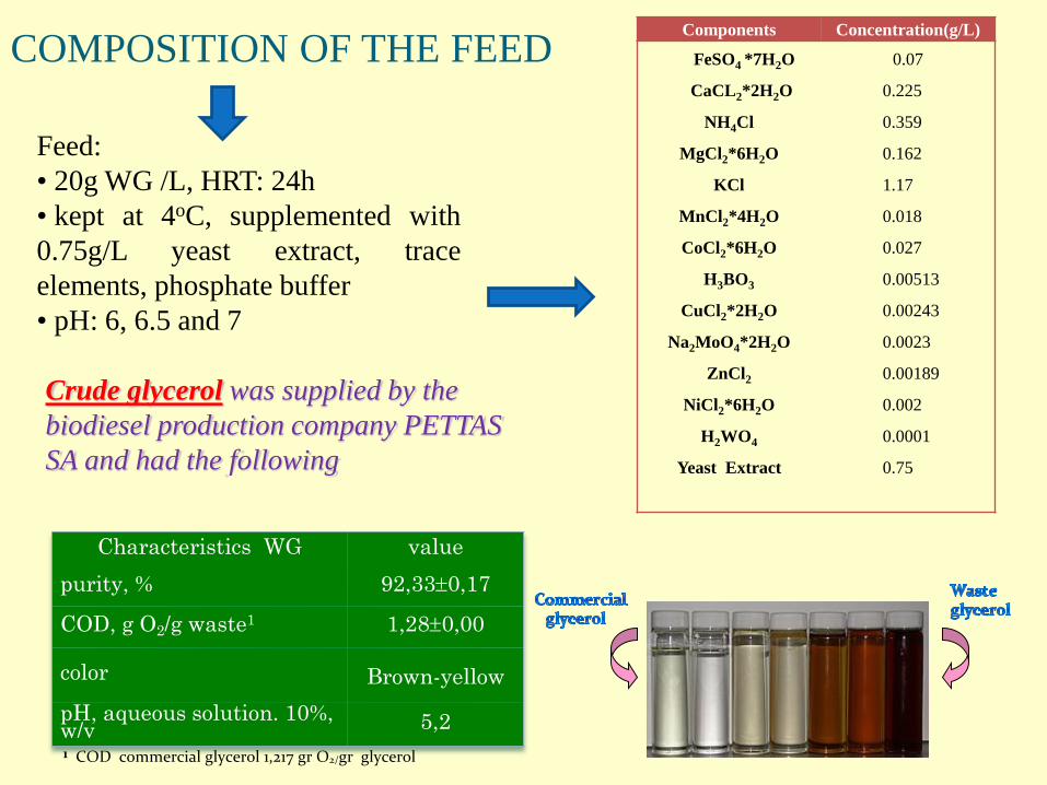
Components Concentration(g/L)
FeSO4 *7H2O
CaCL2*2H2O
NH4Cl
MgCl2*6H2O
KCl
MnCl2*4H2O
CoCl2*6H2O
H3BO3
CuCl2*2H2O
Na2MoO4*2H2O
ZnCl2
NiCl2*6H2O
H2WO4
Yeast Extract
0.07
0.225
0.359
0.162
1.17
0.018
0.027
0.00513
0.00243
0.0023
0.00189
0.002
0.0001
0.75
COMPOSITION OF THE FEED
Feed:
• 20g WG /L, HRT: 24h
• kept at 4oC, supplemented with
0.75g/L yeast extract, trace
elements, phosphate buffer
• pH: 6, 6.5 and 7
Crude glycerol was supplied by the
biodiesel production company PETTAS
SA and had the following
1 COD commercial glycerol 1,217 gr O2/gr glycerol
Characteristics WG value
purity, % 92,330,17
COD, g O2/g waste1 1,280,00
color Brown-yellow
pH, aqueous solution. 10%, w/v 5,2
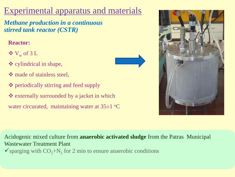
Experimental apparatus and materials
Reactor:
Vw of 3 L
cylindrical in shape,
made of stainless steel,
periodically stirring and feed supply
externally surrounded by a jacket in which
water circurated, maintaining water at 35±1 oC
Acidogenic mixed culture from anaerobic activated sludge from the Patras Municipal
Wastewater Treatment Plant
sparging with CO2+N2 for 2 min to ensure anaerobic conditions
Methane production in a continuous stirred tank reactor (CSTR)
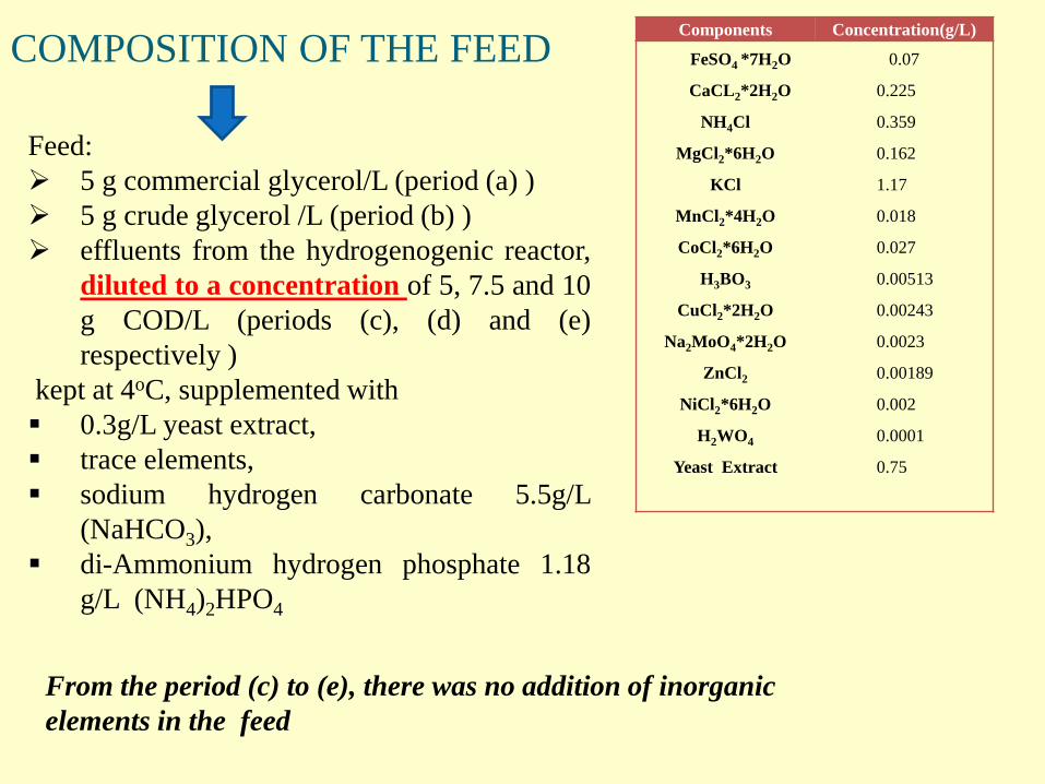
Components Concentration(g/L)
FeSO4 *7H2O
CaCL2*2H2O
NH4Cl
MgCl2*6H2O
KCl
MnCl2*4H2O
CoCl2*6H2O
H3BO3
CuCl2*2H2O
Na2MoO4*2H2O
ZnCl2
NiCl2*6H2O
H2WO4
Yeast Extract
0.07
0.225
0.359
0.162
1.17
0.018
0.027
0.00513
0.00243
0.0023
0.00189
0.002
0.0001
0.75
COMPOSITION OF THE FEED
Feed:
5 g commercial glycerol/L (period (a) )
5 g crude glycerol /L (period (b) )
effluents from the hydrogenogenic reactor,
diluted to a concentration of 5, 7.5 and 10
g COD/L (periods (c), (d) and (e)
respectively )
kept at 4oC, supplemented with
0.3g/L yeast extract,
trace elements,
sodium hydrogen carbonate 5.5g/L
(NaHCO3),
di-Ammonium hydrogen phosphate 1.18
g/L (NH4)2HPO4
From the period (c) to (e), there was no addition of inorganic
elements in the feed
The bioreactor was operated in batch mode for 24h and subsequently,
in continuous mode at an HRT of 24h and a feed pH of 6, 6.5 and 7
The concentration of waste glycerol in the feed was 20g / L
Sampling:
daily from reactor
parameters monitored: T.S.S., V.S.S., d-COD,
glycerol, PDO, VFAs, alcohols, pH, % H2, Vbiogas
1st stage : hydrogen production
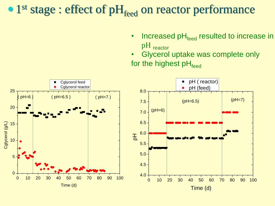
• Increased pHfeed resulted to increase in
pH reactor
• Glycerol uptake was complete only
for the highest pHfeed
0 10 20 30 40 50 60 70 80 90 1000
5
10
15
20
25
Cglycerol feed
Cglycerol reactor
Cgly
cero
l (g
/L)
Time (d)
( pH=6 ) ( pH=6.5 ) ( pH=7 )
1st stage : effect of pHfeed on reactor performance
0 10 20 30 40 50 60 70 80 90 1004.0
4.5
5.0
5.5
6.0
6.5
7.0
7.5
8.0
(pH=7)
pH ( reactor)
pH (feed)
pH
Time (d)
(pH=6)
(pH=6.5)
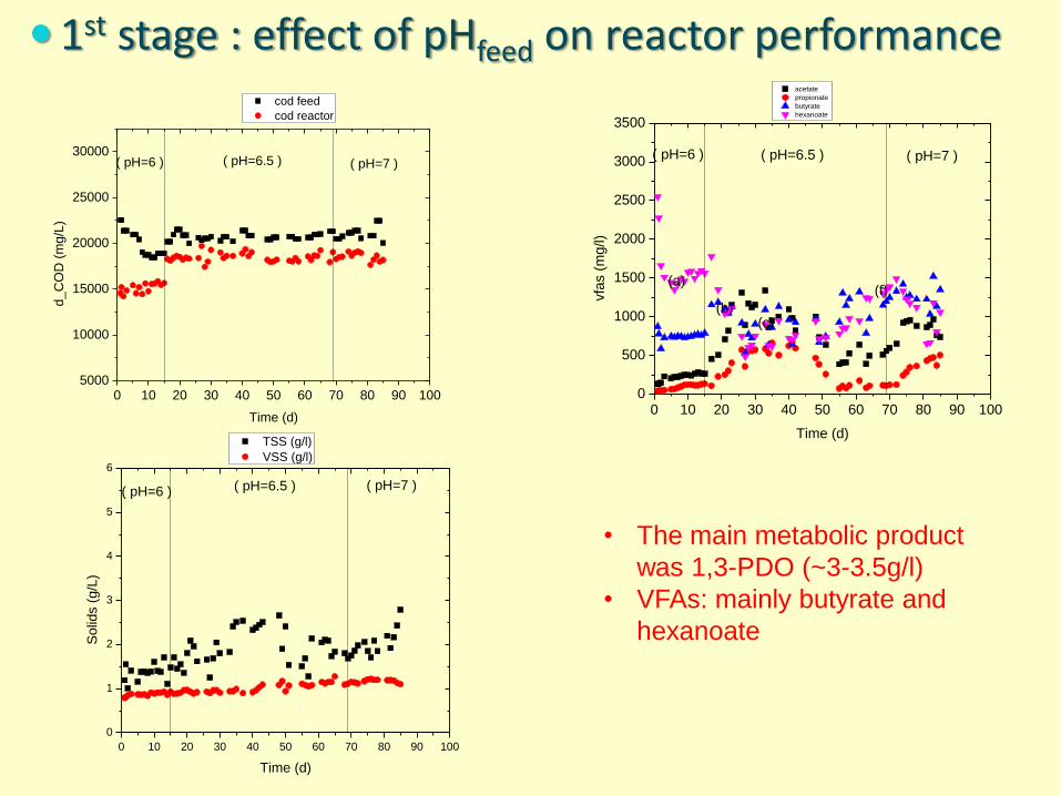
• The main metabolic product
was 1,3-PDO (~3-3.5g/l)
• VFAs: mainly butyrate and
hexanoate
0 10 20 30 40 50 60 70 80 90 100
0
1
2
3
4
5
6
TSS (g/l)
VSS (g/l)
So
lids (
g/L
)
Time (d)
( pH=6 ) ( pH=6.5 ) ( pH=7 )
0 10 20 30 40 50 60 70 80 90 1000
500
1000
1500
2000
2500
3000
3500
(f)
(c)(b)
acetate
propionate
butyrate
hexanoate
vfa
s (
mg/l)
Time (d)
(a)
( pH=6 ) ( pH=6.5 ) ( pH=7 )
1st stage : effect of pHfeed on reactor performance
0 10 20 30 40 50 60 70 80 90 1005000
10000
15000
20000
25000
30000
cod feed
cod reactor
d_C
OD
(m
g/L
)
Time (d)
( pH=6 ) ( pH=6.5 ) ( pH=7 )
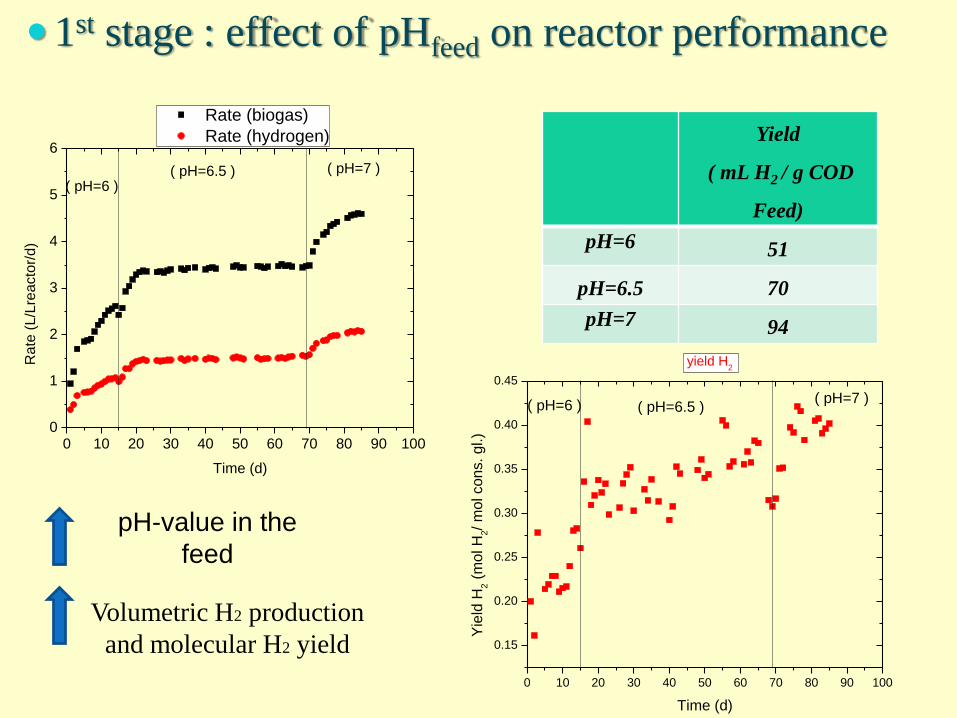
pH-value in the
feed
Volumetric H2 production
and molecular H2 yield
0 10 20 30 40 50 60 70 80 90 1000
1
2
3
4
5
6
( pH=6 )( pH=6.5 ) ( pH=7 )
Rate (biogas)
Rate (hydrogen)
Rate
(L/L
reacto
r/d)
Time (d)
0 10 20 30 40 50 60 70 80 90 100
0.15
0.20
0.25
0.30
0.35
0.40
0.45
yield H2
Yie
ld H
2 (
mol H
2/ m
ol cons. gl.)
Time (d)
( pH=7 )( pH=6.5 )( pH=6 )
1st stage : effect of pHfeed on reactor performance
Yield
( mL H2 / g COD
Feed)
pH=6 51
pH=6.5 70
pH=7 94
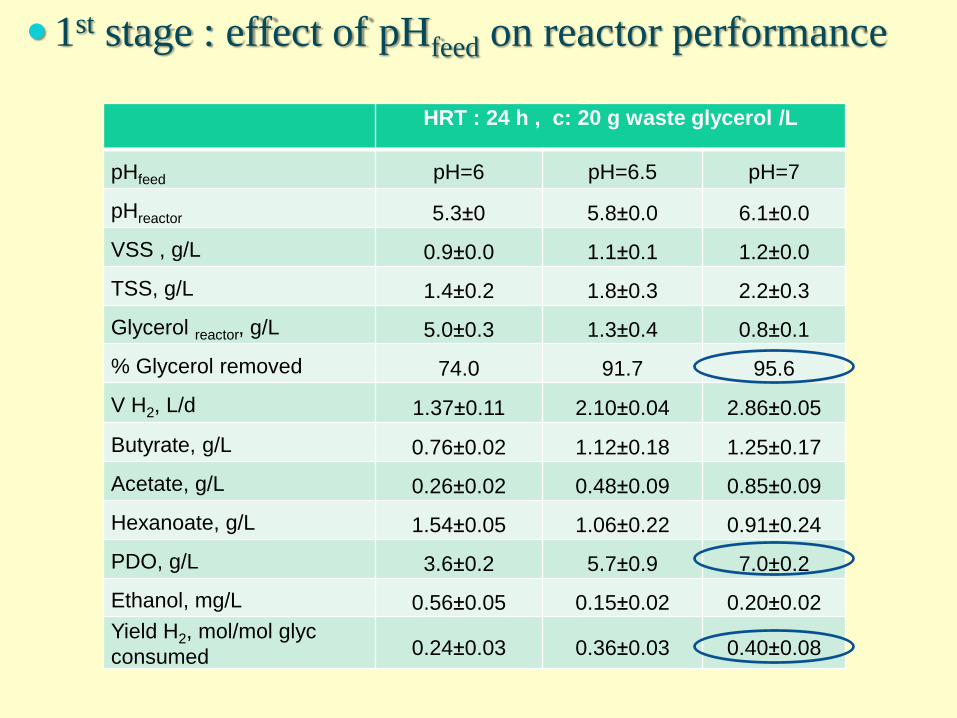
HRT : 24 h , c: 20 g waste glycerol /L
pHfeed pH=6 pH=6.5 pH=7
pHreactor 5.3±0 5.8±0.0 6.1±0.0
VSS , g/L 0.9±0.0 1.1±0.1 1.2±0.0
TSS, g/L 1.4±0.2 1.8±0.3 2.2±0.3
Glycerol reactor, g/L 5.0±0.3 1.3±0.4 0.8±0.1
% Glycerol removed 74.0 91.7 95.6
V H2, L/d 1.37±0.11 2.10±0.04 2.86±0.05
Butyrate, g/L 0.76±0.02 1.12±0.18 1.25±0.17
Acetate, g/L 0.26±0.02 0.48±0.09 0.85±0.09
Hexanoate, g/L 1.54±0.05 1.06±0.22 0.91±0.24
PDO, g/L 3.6±0.2 5.7±0.9 7.0±0.2
Ethanol, mg/L 0.56±0.05 0.15±0.02 0.20±0.02
Yield H2, mol/mol glyc
consumed 0.24±0.03 0.36±0.03 0.40±0.08
1st stage : effect of pHfeed on reactor performance
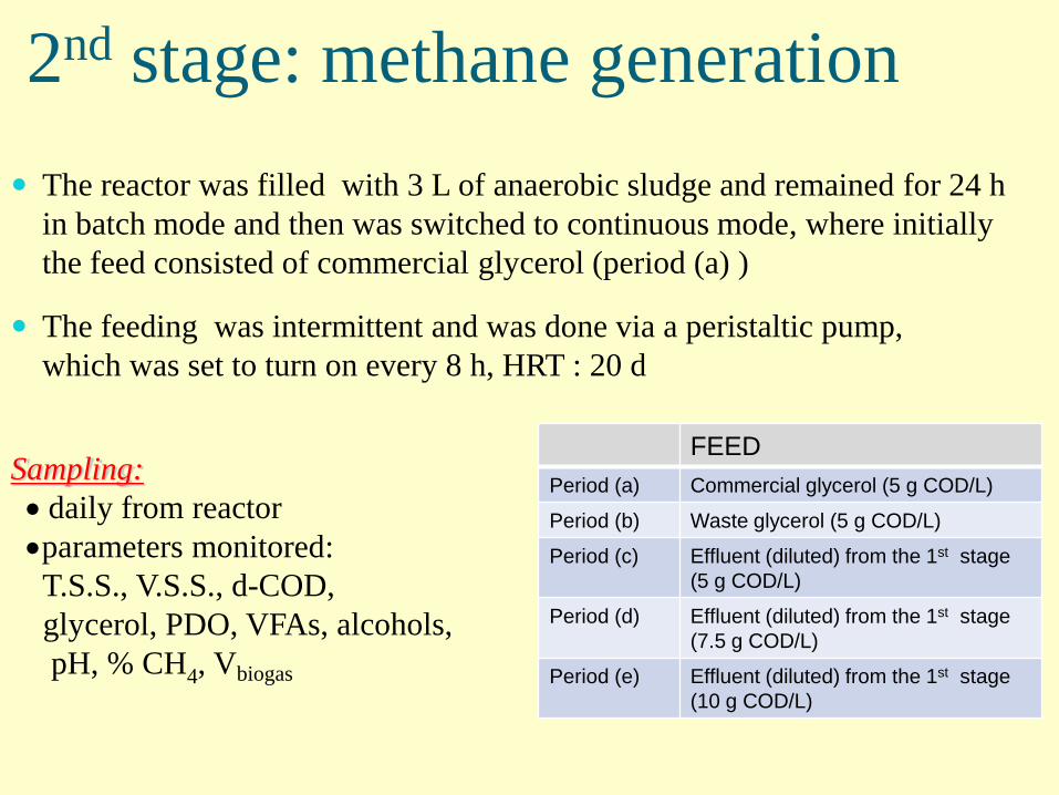
The reactor was filled with 3 L of anaerobic sludge and remained for 24 h
in batch mode and then was switched to continuous mode, where initially
the feed consisted of commercial glycerol (period (a) )
The feeding was intermittent and was done via a peristaltic pump,
which was set to turn on every 8 h, HRT : 20 d
Sampling:
daily from reactor
parameters monitored:
T.S.S., V.S.S., d-COD,
glycerol, PDO, VFAs, alcohols,
pH, % CH4, Vbiogas
2nd stage: methane generation
FEED
Period (a) Commercial glycerol (5 g COD/L)
Period (b) Waste glycerol (5 g COD/L)
Period (c) Effluent (diluted) from the 1st stage
(5 g COD/L)
Period (d) Effluent (diluted) from the 1st stage
(7.5 g COD/L)
Period (e) Effluent (diluted) from the 1st stage
(10 g COD/L)
0 20 40 60 80 100 120 140 160
0.00
0.05
0.10
0.15
0.20
0.25
rate biogas (L/Lreactor/d)
rate methane (L/Lreactor/d)
rate
gase
s (
L/L
rea
cto
r/d)
Time (d)
(a) (b) (c) (d) (e)
0 20 40 60 80 100 120 140 160
0
10
20
30
40
50
60
70
80
90
100
% CH4
% m
eth
ane
time (d)
(a) (b) (c) (d) (e)
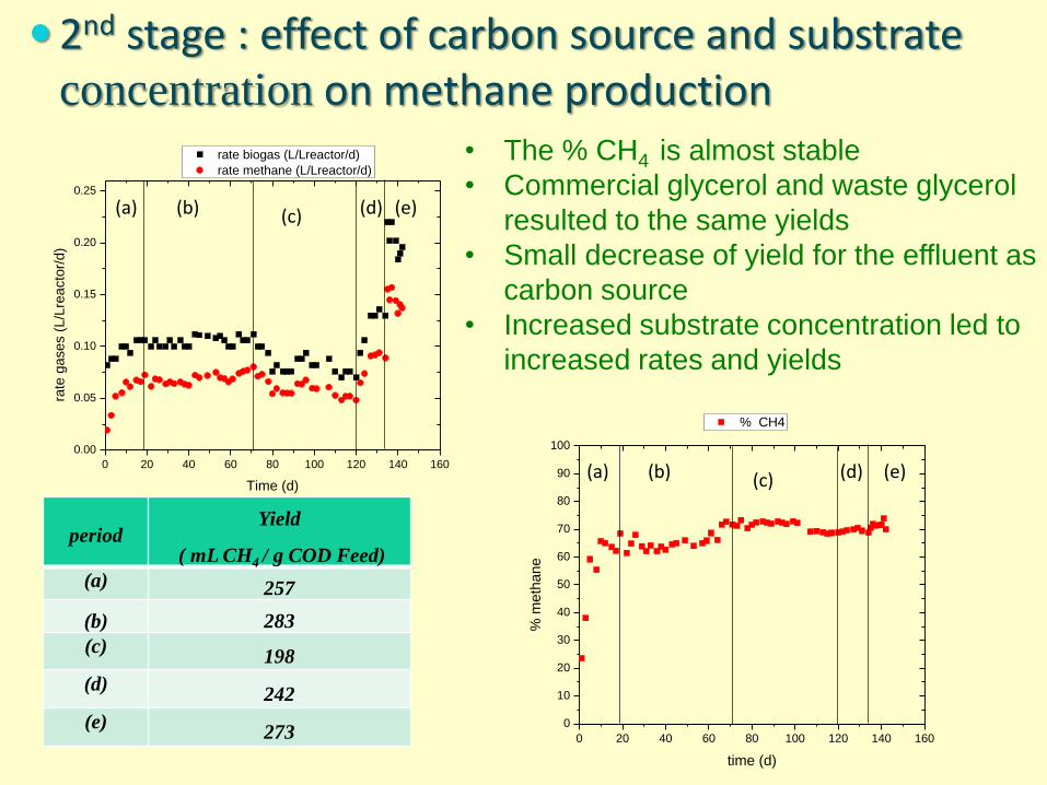
• The % CH4 is almost stable
• Commercial glycerol and waste glycerol
resulted to the same yields
• Small decrease of yield for the effluent as
carbon source
• Increased substrate concentration led to
increased rates and yields
2nd stage : effect of carbon source and substrate concentration on methane production
periodYield
( mL CH4 / g COD Feed)
(a) 257
(b) 283
(c)198
(d)242
(e)273
0 20 40 60 80 100 120 140 160
0
2000
4000
6000
8000
10000
12000
cod reactor (mg/L)
cod feed (mg/L)
d_C
OD
(m
g/L
)
Time (d)
(a) (b) (c)(d)
(e)
0 20 40 60 80 100 120 140 160
0
2
4
6
8
10
12
14
16
18
TSS (g/L)
VSS (g/L)
solid
s (
g/L
)
time (d)
(a) (b) (c)(d)
(e)
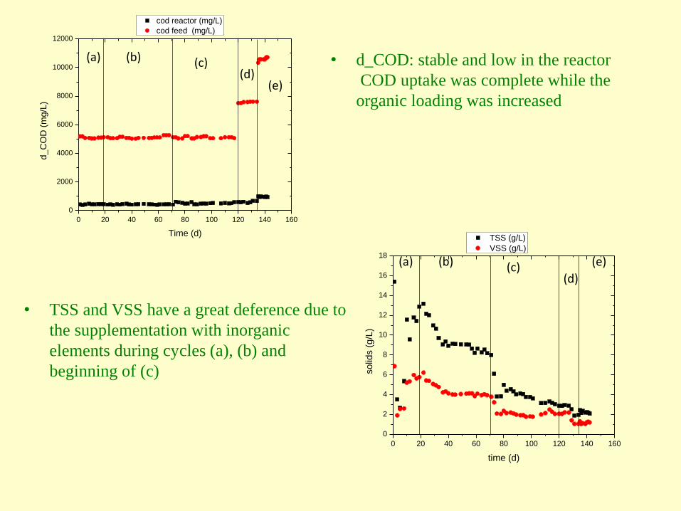
• d_COD: stable and low in the reactor
COD uptake was complete while the
organic loading was increased
• TSS and VSS have a great deference due to
the supplementation with inorganic
elements during cycles (a), (b) and
beginning of (c)
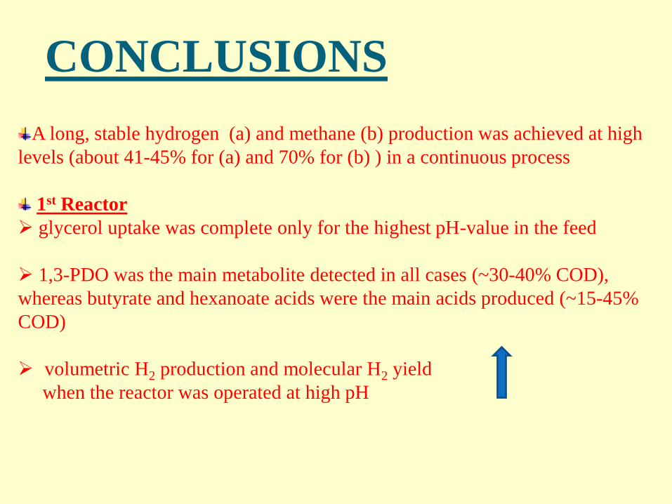
A long, stable hydrogen (a) and methane (b) production was achieved at high
levels (about 41-45% for (a) and 70% for (b) ) in a continuous process
1st Reactor
glycerol uptake was complete only for the highest pH-value in the feed
1,3-PDO was the main metabolite detected in all cases (~30-40% COD),
whereas butyrate and hexanoate acids were the main acids produced (~15-45%
COD)
volumetric H2 production and molecular H2 yield
when the reactor was operated at high pH
CONCLUSIONS
2nd Reactor
The results were satisfactory for methane production
the amount of methane generated was approximately the same for
periods (a) and (b)
For periods (c), (d) and (e) (the feed was the effluent from the 1st
reactor), initially there was a decrease (35%) in the methane production
and at the end an increase (from 17.5% to 70.66%).
VFAs, glycerol, 1.3-propanediol, ethanol were not detectable
in contrast to the 1st reactor
CONCLUSIONS
Further investigation
The dilution of the 1st reactor will be diluted less aiming at feeding
to the CSTR (2nd reactor) the undiluted effluent .
This may require a higher retention time (risk for digester instability)
ACKNOWLEDGEMENTS
The authors would like to thank GSRT for funding
the above study in the framework of the project
BIOREF, 09SYN-81-715.
Information:Α. S. Dounavis
Ph.D. Candidate, Chemical Engineer B.S. and M.S.
FORTH/ICEHTLaboratory of Biochemical Engineering &
Environmental Technology +30 2610 965317 +30 2610 965318
Thank you very much for
your attention!!!