Product Catalog Tracer™ AH - Heating and Air ... · The Tracer AH.540 air handler controller is a...
12
©American Standard Inc. 2001 Product Catalog Tracer™ AH.540 Air Handler Controller January 2001 CNT-PRC001-EN
Transcript of Product Catalog Tracer™ AH - Heating and Air ... · The Tracer AH.540 air handler controller is a...
©American Standard Inc. 2001
Product Catalog
Tracer™ AH.540
Air Handler Controller
January 2001 CNT-PRC001-EN
2 CNT-PRC001-EN
Contents Introduction............................................................................................2 Tracer AH.540 Benefits ........................................................................2 Controller Features...............................................................................4 Physical Specifications.........................................................................5 Control Points........................................................................................6 Air Handler Control Applications.....................................................11
Introduction
The Tracer AH.540 air handler controller is a cost-effective, direct digital controller in the Tracer controls product family. The Tracer AH.540 is available for a variety of common air handler configurations and is offered on the following Trane® air handler product lines:
o The indoor Modular Climate Changer® (MCC) air handler o The outdoor T-Series Climate Changer (TSC) air handler o The indoor Packaged Climate Changer (LPC) air handler
Selection of Trane as a single-source provider for air handlers and controls results in superior reliability, consistency and satisfaction.
Tracer AH.540 Benefits
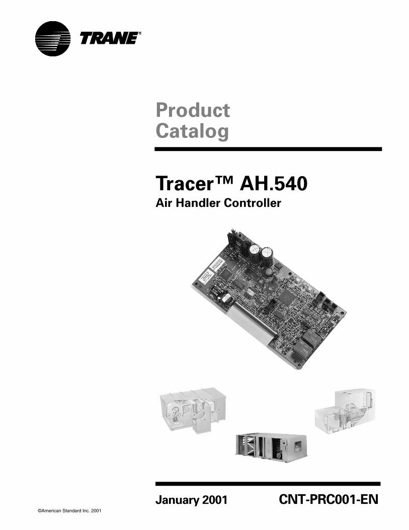
The Tracer AH.540 brings many important benefits with its offering. The most important of these benefits are described in Table 1.
Table 1. Tracer AH.540 benefits
Benefit Description
Limited field commissioning
The Tracer AH.540 enables quicker completion of the mechanical, air handler controls and BAS startups. There is limited field commissioning required since the controller is mounted, wired, programmed and tested in the factory.
Value The Tracer AH.540 provides a total cost improvement, making digital controls affordable for any air handler. This improvement includes not only a competitively priced controller, but also competitively priced installation and commissioning when purchased as a factory-installed option on a Trane air handler.
Configuration flexibility
The Tracer AH.540 is designed to meet a variety of common air handler configurations. It provides a straightforward option to meet the majority of specific control system requirements. See the "Control Points" section for more information on configurations.
CNT-PRC001-EN 3
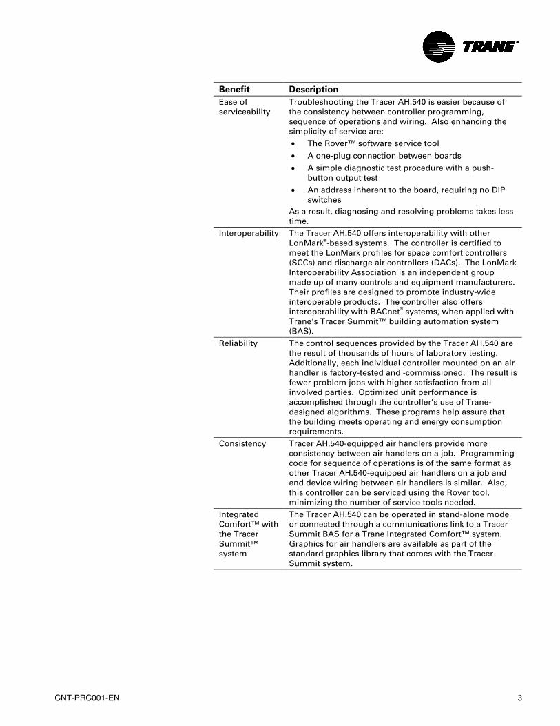
Benefit Description
Ease of serviceability
Troubleshooting the Tracer AH.540 is easier because of the consistency between controller programming, sequence of operations and wiring. Also enhancing the simplicity of service are: • The Rover™ software service tool • A one-plug connection between boards • A simple diagnostic test procedure with a push-
button output test • An address inherent to the board, requiring no DIP
switches As a result, diagnosing and resolving problems takes less time.
Interoperability The Tracer AH.540 offers interoperability with other LonMark®-based systems. The controller is certified to meet the LonMark profiles for space comfort controllers (SCCs) and discharge air controllers (DACs). The LonMark Interoperability Association is an independent group made up of many controls and equipment manufacturers. Their profiles are designed to promote industry-wide interoperable products. The controller also offers interoperability with BACnet® systems, when applied with Trane's Tracer Summit™ building automation system (BAS).
Reliability The control sequences provided by the Tracer AH.540 are the result of thousands of hours of laboratory testing. Additionally, each individual controller mounted on an air handler is factory-tested and -commissioned. The result is fewer problem jobs with higher satisfaction from all involved parties. Optimized unit performance is accomplished through the controller’s use of Trane-designed algorithms. These programs help assure that the building meets operating and energy consumption requirements.
Consistency Tracer AH.540-equipped air handlers provide more consistency between air handlers on a job. Programming code for sequence of operations is of the same format as other Tracer AH.540-equipped air handlers on a job and end device wiring between air handlers is similar. Also, this controller can be serviced using the Rover tool, minimizing the number of service tools needed.
Integrated Comfort™ with the Tracer Summit™ system
The Tracer AH.540 can be operated in stand-alone mode or connected through a communications link to a Tracer Summit BAS for a Trane Integrated Comfort™ system. Graphics for air handlers are available as part of the standard graphics library that comes with the Tracer Summit system.
4 CNT-PRC001-EN
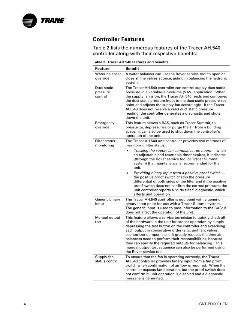
Controller Features
Table 2 lists the numerous features of the Tracer AH.540 controller along with their respective benefits:
Table 2. Tracer AH.540 features and benefits
Feature Benefit
Water balancer override
A water balancer can use the Rover service tool to open or close all the valves at once, aiding in balancing the hydronic system.
Duct static pressure control
The Tracer AH.540 controller can control supply duct static pressure in a variable-air-volume (VAV) application. When the supply fan is on, the Tracer AH.540 reads and compares the duct static pressure input to the duct static pressure set point and adjusts the supply fan accordingly. If the Tracer AH.540 does not receive a valid duct static pressure reading, the controller generates a diagnostic and shuts down the unit.
Emergency override
This feature allows a BAS, such as Tracer Summit, to pressurize, depressurize or purge the air from a building space. It can also be used to shut down the controller's operation of the unit.
Filter status monitoring
The Tracer AH.540 unit controller provides two methods of monitoring filter status: • Tracking the supply fan cumulative run hours — when
an adjustable and resettable timer expires, it indicates (through the Rover service tool or Tracer Summit system) that maintenance is recommended for the unit.
• Providing binary input from a positive proof switch — the positive proof switch checks the pressure differential of both sides of the filter and if the positive proof switch does not confirm the correct pressure, the unit controller reports a "dirty filter" diagnostic, which affects unit operation.
Generic binary input
The Tracer AH.540 controller is equipped with a generic binary input point for use with a Tracer Summit system. The generic input is used to pass information to the BAS; it does not affect the operation of the unit.
Manual output test
This feature allows a service technician to quickly check all of the hardware in the unit for proper operation by simply depressing the test button on the controller and exercising each output in consecutive order (e.g., unit fan, valves, economizer damper, etc.). It greatly reduces the time air balancers need to perform their responsibilities, because they can specify the required outputs for balancing. This manual output test sequence can also be performed using the Rover service tool.
Supply fan status control
To ensure that the fan is operating correctly, the Tracer AH.540 controller provides binary input from a fan proof switch when confirmation of airflow is required. When the controller expects fan operation, but the proof switch does not confirm it, unit operation is disabled and a diagnostic message is generated.
CNT-PRC001-EN 5
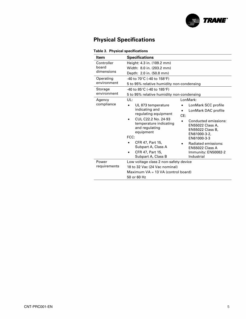
Physical Specifications Table 3. Physical specifications
Item Specifications
Controller board dimensions
Height: 4.3 in. (109.2 mm) Width: 8.0 in. (203.2 mm) Depth: 2.0 in. (50.8 mm)
Operating environment
-40 to 70°C (-40 to 158°F) 5 to 95% relative humidity non-condensing
Storage environment
-40 to 85°C (-40 to 185°F) 5 to 95% relative humidity non-condensing
Agency compliance
UL: • UL 873 temperature
indicating and regulating equipment
• CUL C22.2 No. 24-93 temperature indicating and regulating equipment
FCC: • CFR 47, Part 15,
Subpart A, Class A • CFR 47, Part 15,
Subpart A, Class B
LonMark: • LonMark SCC profile • LonMark DAC profile CE: • Conducted emissions:
EN55022 Class A, EN55022 Class B, EN61000-3-2, EN61000-3-3
• Radiated emissions: EN55022 Class A Immunity: EN50082-2 Industrial
Power requirements
Low voltage class 2 non-safety device 18 to 32 Vac (24 Vac nominal) Maximum VA = 13 VA (control board) 50 or 60 Hz
6 CNT-PRC001-EN
Control Points
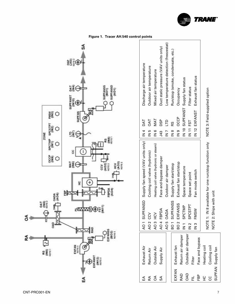
The Tracer AH.540 is configured at the Trane air handler factory per customer requirements. The controller is applied to air-handling product configurations supporting analog modulating valves, economizer dampers and face-and-bypass dampers. The controller supports either a constant volume or variable-air-volume (VAV) supply fan. A unit schematic with control points is shown in Figure 1. The figure shows all available options and functions for the controller and air-handling system. Possible configurations include:
o Cooling only unit o Heating only unit without bypass o Heating only unit with bypass o Cooling and heating unit (coils in either order) without
bypass o Heating and cooling unit (coils in that respective order)
with bypass for the heating coil o Heating and cooling unit (coils in that respective order)
with bypass for both coils
The outputs and inputs are described in the following sections.
CNT-PRC001-EN 7
Figure 1. Tracer AH.540 control points
Dis
char
ge
air
tem
per
atu
re
Ou
tdo
or
air
tem
per
atu
re
Mix
ed a
ir t
emp
erat
ure
Du
ct s
tati
c p
ress
ure
(V
AV
un
its
on
ly)
Low
tem
per
atu
re d
etec
tio
n (
free
zest
at)
Ru
n/s
top
(sm
oke
, co
nd
ensa
te, e
tc.)
Occ
up
ancy
Su
pp
ly f
an s
tatu
s
Filt
er s
tatu
s
Exh
aust
fan
sta
tus
DA
T
OA
T
MA
T
DS
P
LTD
RS
OC
CP
SU
PFA
NS
T
FST
EX
FAN
ST
IN 4
IN 5
IN 6
J43
IN 7
IN 8
IN 9
IN 1
0
IN 1
1
IN 1
2
NO
TE
3: F
ield
-su
pp
lied
op
tio
n
Su
pp
ly f
an s
pee
d (
VA
V u
nit
s o
nly
)
Co
olin
g c
oil
valv
e (h
ydro
nic
)
Hea
ting
coil
valv
e (h
ydro
nic
or s
team
)
Face
-an
d-b
ypas
s d
amp
er
Ou
tdo
or
air
dam
per
Su
pp
ly f
an s
tart
/sto
p
Exh
aust
fan
sta
rt/s
top
Sp
ace
tem
per
atu
re
Sp
ace
set
po
int
Fan
mo
de
swit
ch
SU
PFA
NS
D
CC
V
HC
V
FBP
DA
OA
DA
SU
PFA
NS
S
EX
FAN
SS
SP
CT
MP
SP
CS
TP
T
FMS
W
AO
1
AO
2
AO
3
AO
4
AO
5
BO
1
BO
2
IN 1
IN 2
IN 3
NO
TE
1:
IN 8
ava
ilab
le f
or
on
e ru
n/s
top
fu
nct
ion
on
ly
NO
TE
2: S
hip
s w
ith
un
it
Exh
aust
Air
Ret
urn
Air
Ou
tsid
e A
ir
Su
pp
ly A
ir
Exh
aust
fan
Ret
urn
air
dam
per
Ou
tsid
e ai
r d
amp
er
Filt
er
Face
an
d b
ypas
s
Hea
tin
g c
oil
Co
olin
g c
oil
Su
pp
ly f
an
EA
RA
OA
SA
EX
FAN
RA
D
OA
D
FIL
FBP
HC
CC
SU
PFA
N
8 CNT-PRC001-EN
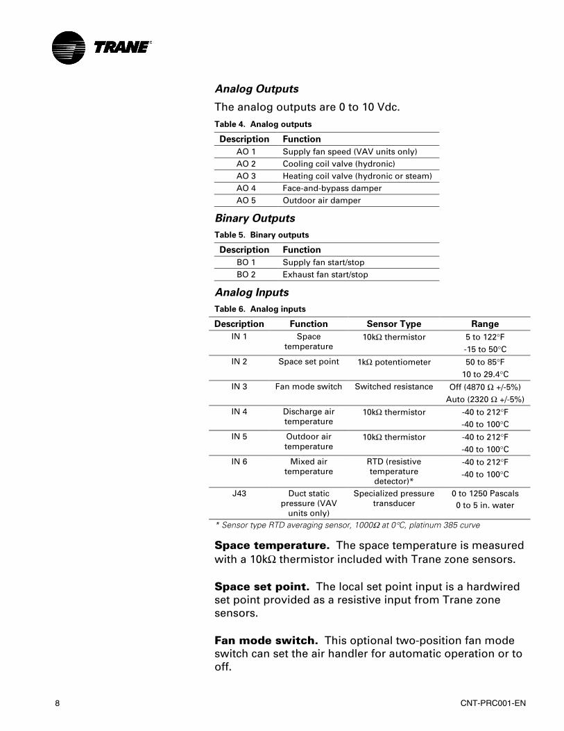
Analog Outputs
The analog outputs are 0 to 10 Vdc. Table 4. Analog outputs
Description Function
AO 1 Supply fan speed (VAV units only) AO 2 Cooling coil valve (hydronic) AO 3 Heating coil valve (hydronic or steam) AO 4 Face-and-bypass damper AO 5 Outdoor air damper
Binary Outputs
Table 5. Binary outputs
Description Function
BO 1 Supply fan start/stop BO 2 Exhaust fan start/stop
Analog Inputs
Table 6. Analog inputs
Description Function Sensor Type Range
IN 1 Space temperature
10kΩ thermistor 5 to 122°F -15 to 50°C
IN 2 Space set point 1kΩ potentiometer 50 to 85°F 10 to 29.4°C
IN 3 Fan mode switch Switched resistance Off (4870 Ω +/-5%) Auto (2320 Ω +/-5%)
IN 4 Discharge air temperature
10kΩ thermistor -40 to 212°F -40 to 100°C
IN 5 Outdoor air temperature
10kΩ thermistor -40 to 212°F -40 to 100°C
IN 6 Mixed air temperature
RTD (resistive temperature detector)*
-40 to 212°F -40 to 100°C
J43 Duct static pressure (VAV
units only)
Specialized pressure transducer
0 to 1250 Pascals 0 to 5 in. water
* Sensor type RTD averaging sensor, 1000Ω at 0°C, platinum 385 curve
Space temperature. The space temperature is measured with a 10kΩ thermistor included with Trane zone sensors.
Space set point. The local set point input is a hardwired set point provided as a resistive input from Trane zone sensors.
Fan mode switch. This optional two-position fan mode switch can set the air handler for automatic operation or to off.
CNT-PRC001-EN 9
Discharge air temperature. The Tracer AH.540 controller uses a 10kΩ thermistor sensor for the discharge air temperature input. This sensor is hardwired and typically located downstream from all heating and cooling coils in the unit. The discharge air temperature is used as a control input to the controller for all control modes of operation: constant volume space temperature control, constant volume discharge air temperature control and VAV control.
Outdoor air temperature. An analog input is used for outdoor air temperature sensing using a 10kΩ thermistor. When a valid outdoor air temperature, either hardwired or communicated, and an economizer outdoor air damper exist, the controller uses the temperature to determine if economizing (free cooling) is feasible. If the outdoor air temperature is below the economizer enabling point, then economizing is allowed. The outdoor air temperature sensor determines if the air handler should enter freeze avoidance mode during unoccupied periods. When the outdoor air temperature is not sensed, then economizing is not allowed.
Mixed air temperature. The Tracer AH.540 uses an analog input for the mixed air temperature input sensing using an averaging, 1000Ω (at 0°C, 32°F) RTD sensor. The controller’s mixed air temperature input is used for mixed air tempering and outdoor air economizing operations.
The Tracer AH.540 controller disallows economizing if the controller does not sense a valid mixed air temperature input.
Duct static pressure. The duct static pressure input interfaces with a specialized pressure transducer. When a valid duct static pressure value exists and a VAV supply fan is present, the controller uses the value for duct static pressure control.
10 CNT-PRC001-EN
Binary Inputs
The Tracer AH.540 has six binary inputs. The default configuration for each binary input (including normally opened or closed) is set at the factory. The function of each input is described in Table 7 below:
Table 7. Binary input functions
Description Function
IN 7 Low temperature detection (low-limit) IN 8 Run/stop (smoke, condensate, etc.) IN 9 Occupancy
IN 10 Supply fan status IN 11 Filter status IN 12 Exhaust fan status
Low temperature detection. Low temperature detection protects the coils of hydronic units. When the controller detects the low temperature detection signal, the controller generates a diagnostic which disables the fan, opens all unit hydronic or steam valves and closes the outdoor air damper (when present).
When steam is the source of heat, the heat valve is cycled opened and closed when the controller is shutdown on a low temperature detection. Cycling the steam valve helps prevent excessive cabinet temperature.
Run/stop. The run/stop hardwired binary input can be used for a variety of functions to shut down the unit. The Tracer AH.540 controller systematically shuts down unit operation and reports a unit shutdown diagnostic upon detecting a stop input. For example, a condensate overflow sensor or a smoke detector can be connected to the run/stop input to shutdown unit operation.
Occupancy. The Tracer AH.540 controller uses the occupancy binary input for two occupancy-related functions.
For stand-alone controllers (any unit not receiving a communicated occupancy request, typically from a BAS), the occupancy binary input determines the unit's occupancy based on the hardwired signal. Normally, the input is hardwired to an occupancy sensor or time clock.
For controllers that receive a communicated occupancy request (typically from a BAS), the hardwired occupancy
CNT-PRC001-EN 11
binary input, along with the communicated occupancy request, place the controller in either occupied mode or occupied standby mode. When the controller receives a communicated unoccupied request, the controller operates according to the unoccupied set points regardless of the state of the hardwired occupancy input.
When no wired or communicated input is available the controller defaults to occupied mode.
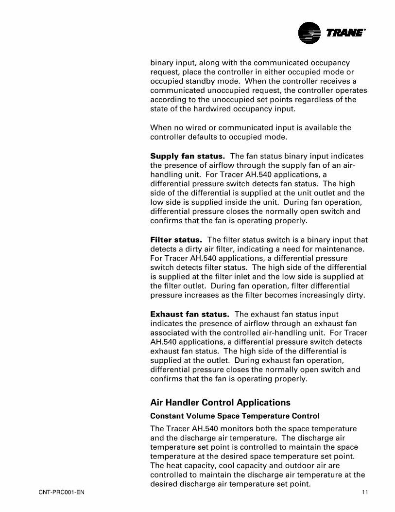
Supply fan status. The fan status binary input indicates the presence of airflow through the supply fan of an air-handling unit. For Tracer AH.540 applications, a differential pressure switch detects fan status. The high side of the differential is supplied at the unit outlet and the low side is supplied inside the unit. During fan operation, differential pressure closes the normally open switch and confirms that the fan is operating properly.
Filter status. The filter status switch is a binary input that detects a dirty air filter, indicating a need for maintenance. For Tracer AH.540 applications, a differential pressure switch detects filter status. The high side of the differential is supplied at the filter inlet and the low side is supplied at the filter outlet. During fan operation, filter differential pressure increases as the filter becomes increasingly dirty.
Exhaust fan status. The exhaust fan status input indicates the presence of airflow through an exhaust fan associated with the controlled air-handling unit. For Tracer AH.540 applications, a differential pressure switch detects exhaust fan status. The high side of the differential is supplied at the outlet. During exhaust fan operation, differential pressure closes the normally open switch and confirms that the fan is operating properly.
Air Handler Control Applications
Constant Volume Space Temperature Control
The Tracer AH.540 monitors both the space temperature and the discharge air temperature. The discharge air temperature set point is controlled to maintain the space temperature at the desired space temperature set point. The heat capacity, cool capacity and outdoor air are controlled to maintain the discharge air temperature at the desired discharge air temperature set point.
12 CNT-PRC001-EN
Constant Volume Discharge Air Control
The Tracer AH.540 monitors the discharge air temperature. The heat capacity, cool capacity and outdoor air are controlled to maintain the discharge air temperature at the desired discharge air temperature set point.
Variable-Air-Volume Control
The Tracer AH.540 monitors both the discharge air temperature and the duct static pressure. The supply fan speed is controlled to maintain the duct static pressure at the desired duct static pressure set point. The heat capacity, cool capacity and outdoor air are controlled to maintain the discharge air temperature at the desired discharge air temperature set point.
Literature Order Number CNT-PRC001-EN File Number PL-ES-CNT-PRC-001-EN-0101 Supersedes New Stocking Location La Crosse Since The Trane Company has a policy of continuous product and product data improvement, it reserves the right to change design and specifications without notice.
The Trane Company An American Standard Company www.trane.com For more information, contact your local district office or e-mail us at [email protected]


![DISSERTATION - qucosa.de · Charakterisierung von 16α-[18F]Fluorestradiol-3,17β-disulfamat als potentieller Tracer für die Positronen-Emissions-Tomographie DISSERTATION](https://static.fdocument.org/doc/165x107/5b0e50c67f8b9a2c3b8e8309/dissertation-von-16-18ffluorestradiol-317-disulfamat-als-potentieller-tracer.jpg)