Practical Considerations in the Design of Thermoelectric ...
20
Practical Considerations in the Design of Thermoelectric Power Systems. Professor Andrew Knox [email protected] / 0141 330 4253 Andrea Montecucco EPSRC Thermoelectrics Network Meeting Manchester, 25 th /26 th February 2014 1 Andrea Montecucco
Transcript of Practical Considerations in the Design of Thermoelectric ...
Practical Considerations in the Design of Thermoelectric Power Systems.
Professor Andrew [email protected] / 0141 330 4253
Andrea Montecucco
EPSRC Thermoelectrics Network MeetingManchester, 25th/26th February 2014
1
Andrea Montecucco
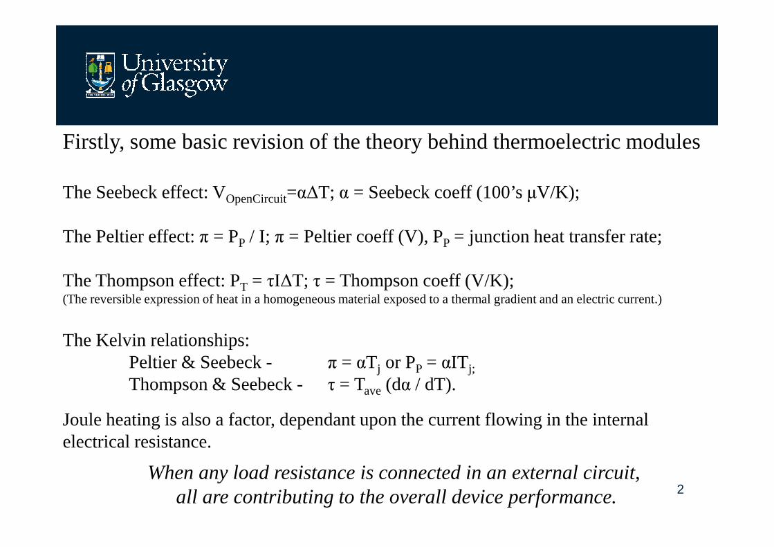
Firstly, some basic revision of the theory behind thermoelectric modules
The Seebeck effect: VOpenCircuit=α∆T; α = Seebeck coeff (100’s µV/K);
The Peltier effect: π = PP / I; π = Peltier coeff (V), PP = junction heat transfer rate;
The Thompson effect: P= τI∆T; τ = Thompson coeff (V/K);
2
The Thompson effect: PT = τI∆T; τ = Thompson coeff (V/K);(The reversible expression of heat in a homogeneous material exposed to a thermal gradient and an electric current.)
The Kelvin relationships: Peltier & Seebeck - π = αTj or PP = αIT j;
Thompson & Seebeck - τ = Tave(dα / dT).
Joule heating is also a factor, dependant upon the current flowing in the internal electrical resistance.
When any load resistance is connected in an external circuit, all are contributing to the overall device performance.
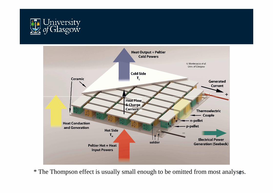
3* The Thompson effect is usually small enough to be omitted from most analyses.
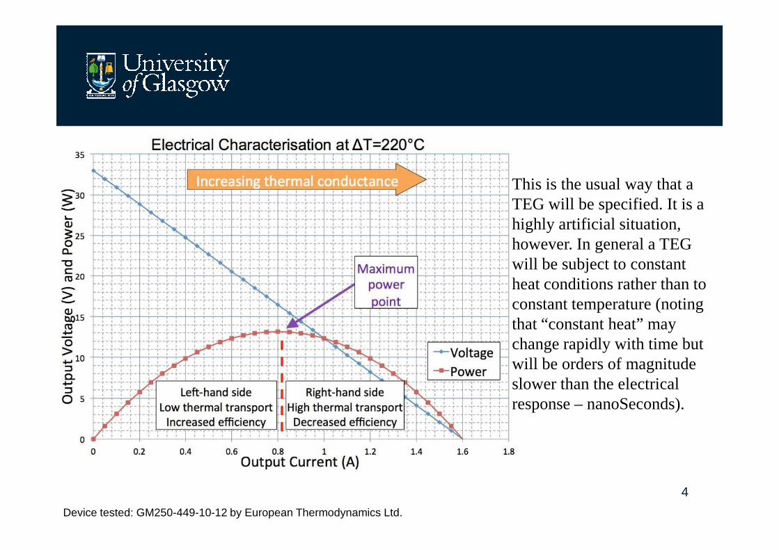
This is the usual way that a TEG will be specified. It is a highly artificial situation, however. In general a TEG will be subject to constant heat conditions rather than to
4
Device tested: GM250-449-10-12 by European Thermodynamics Ltd.
heat conditions rather than to constant temperature (noting that “constant heat” may change rapidly with time but will be orders of magnitude slower than the electrical response – nanoSeconds).

Simulation of thermoelectric systems
Mathematical ModelSimulink Model
5Looking only at the TEG in isolation will produce misleading results!
Montecucco, Knox, “Accurate simulation of thermoelectric power generating systems,” Applied Energy, 2014. doi: 10.1016/j.apenergy.2013.12.028
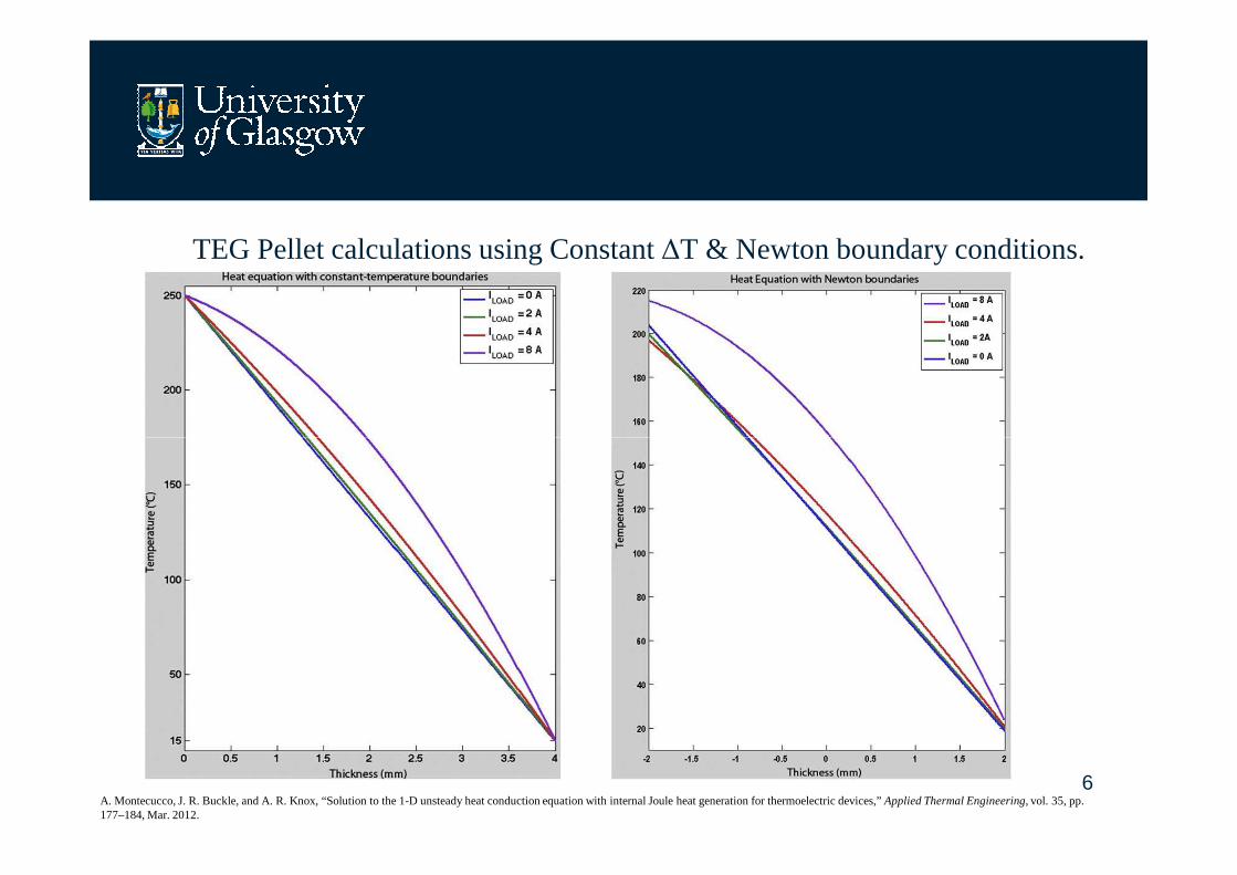
TEG Pellet calculations using Constant ∆T & Newton boundary conditions.
6A. Montecucco, J. R. Buckle, and A. R. Knox, “Solution to the 1-D unsteady heat conduction equation with internal Joule heat generation for thermoelectric devices,” Applied Thermal Engineering, vol. 35, pp. 177–184, Mar. 2012.
Thermal considerations in thermoelectric systems.
• The “cold” side can be < 0°C, but beware ingress of water – freezing near the pellets will result in permanent module open-circuit.
• The “hot” side maximum temp. is usually determined by the melting point of the solder holding the TEG together. (Wires on “cold side”).
7
• Differential expansion due to high ∆T results in large lateral shear stresses, especially in the corners. (Limits the size of metallized TEGs to ~25 x 25mm.)
• Mechanical compliance is needed to ensure correct clamping pressure is maintained over the operating temperature range.
• Ensure there are no hot-spots: module temperature uniformity on BOTH sides is needed, over the entire surface area of the TEG. Mounting flatness is critical.
• Multi-TEG planar clamping systems have inherent mechanical design difficulty due to variable TEG thickness & flatness and unequal pressure.
• Frequently it is the temperature on the cold side that has the greatest impact on overall system performance.
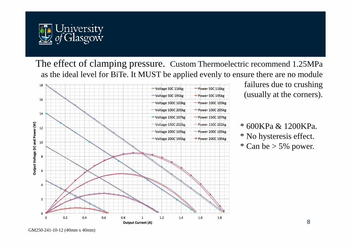
The effect of clamping pressure. Custom Thermoelectric recommend 1.25MPa as the ideal level for BiTe. It MUST be applied evenly to ensure there are no module
failures due to crushing(usually at the corners).
* 600KPa & 1200KPa.
8GM250-241-10-12 (40mm x 40mm)
* 600KPa & 1200KPa.* No hysteresis effect.* Can be > 5% power.
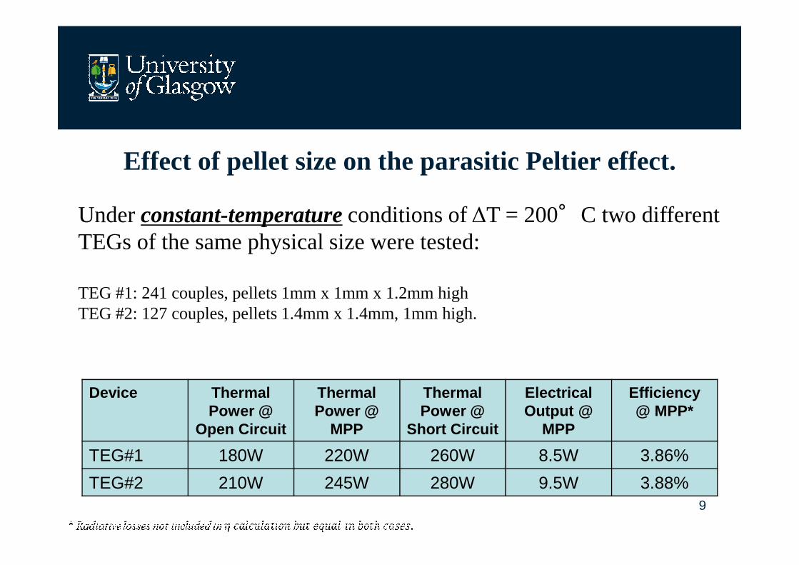
Effect of pellet size on the parasitic Peltier effect.
Under constant-temperatureconditions of ∆T = 200°C two different TEGs of the same physical size were tested:
9
TEG #1: 241 couples, pellets 1mm x 1mm x 1.2mm highTEG #2: 127 couples, pellets 1.4mm x 1.4mm, 1mm high.
Device Thermal Power @
Open Circuit
Thermal Power @
MPP
Thermal Power @
Short Circuit
ElectricalOutput @
MPP
Efficiency@ MPP*
TEG#1 180W 220W 260W 8.5W 3.86%
TEG#2 210W 245W 280W 9.5W 3.88%
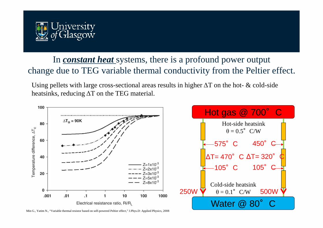
In constant heat systems, there is a profound power output change due to TEG variable thermal conductivity from the Peltier effect.
Using pellets with large cross-sectional areas results in higher ∆T on the hot- & cold-side heatsinks, reducing ∆T on the TEG material.
Hot gas @ 700°C
10Min G., Yatim N., “Variable thermal resistor based on self-powered Peltier effect,” J.Phys.D: Applied Physics, 2008
Hot gas @ 700°CHot-side heatsinkθ = 0.5°C/W
Cold-side heatsinkθ = 0.1°C/W
Water @ 80°C250W 500W
575°C
105°C
∆T= 470°C
450°C
105°C
∆T= 320°C
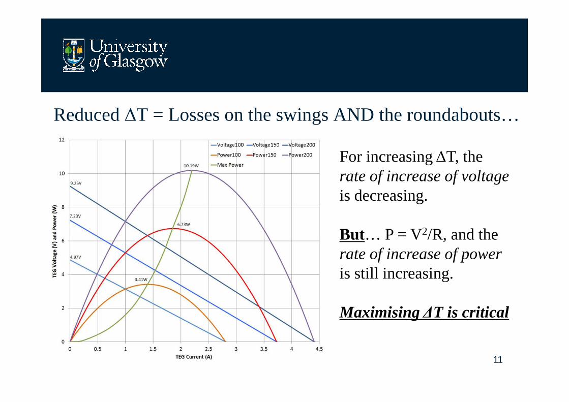
Reduced ∆T = Losses on the swings AND the roundabouts…
For increasing ∆T, the rate of increase of voltage is decreasing.
11
is decreasing.
But… P = V2/R, and therate of increase of power is still increasing.
Maximising ∆T is critical
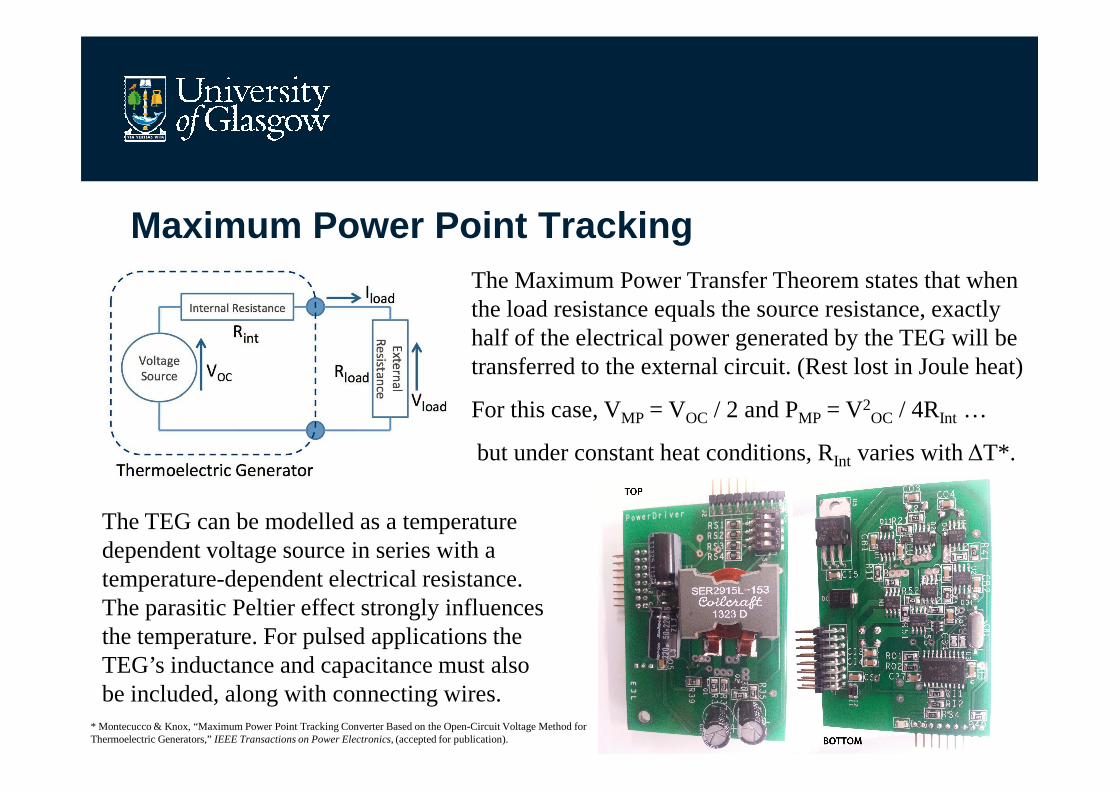
Maximum Power Point TrackingThe Maximum Power Transfer Theorem states that when the load resistance equals the source resistance, exactly half of the electrical power generated by the TEG will be transferred to the external circuit. (Rest lost in Joule heat)
12
For this case, VMP = VOC / 2 and PMP = V2OC / 4RInt …
but under constant heat conditions, RInt varies with ∆T*.
The TEG can be modelled as a temperature dependent voltage source in series with a temperature-dependent electrical resistance. The parasitic Peltier effect strongly influences the temperature. For pulsed applications the TEG’s inductance and capacitance must also be included, along with connecting wires.
* Montecucco & Knox, “Maximum Power Point Tracking Converter Based on the Open-Circuit Voltage Method for Thermoelectric Generators,” IEEE Transactions on Power Electronics, (accepted for publication).
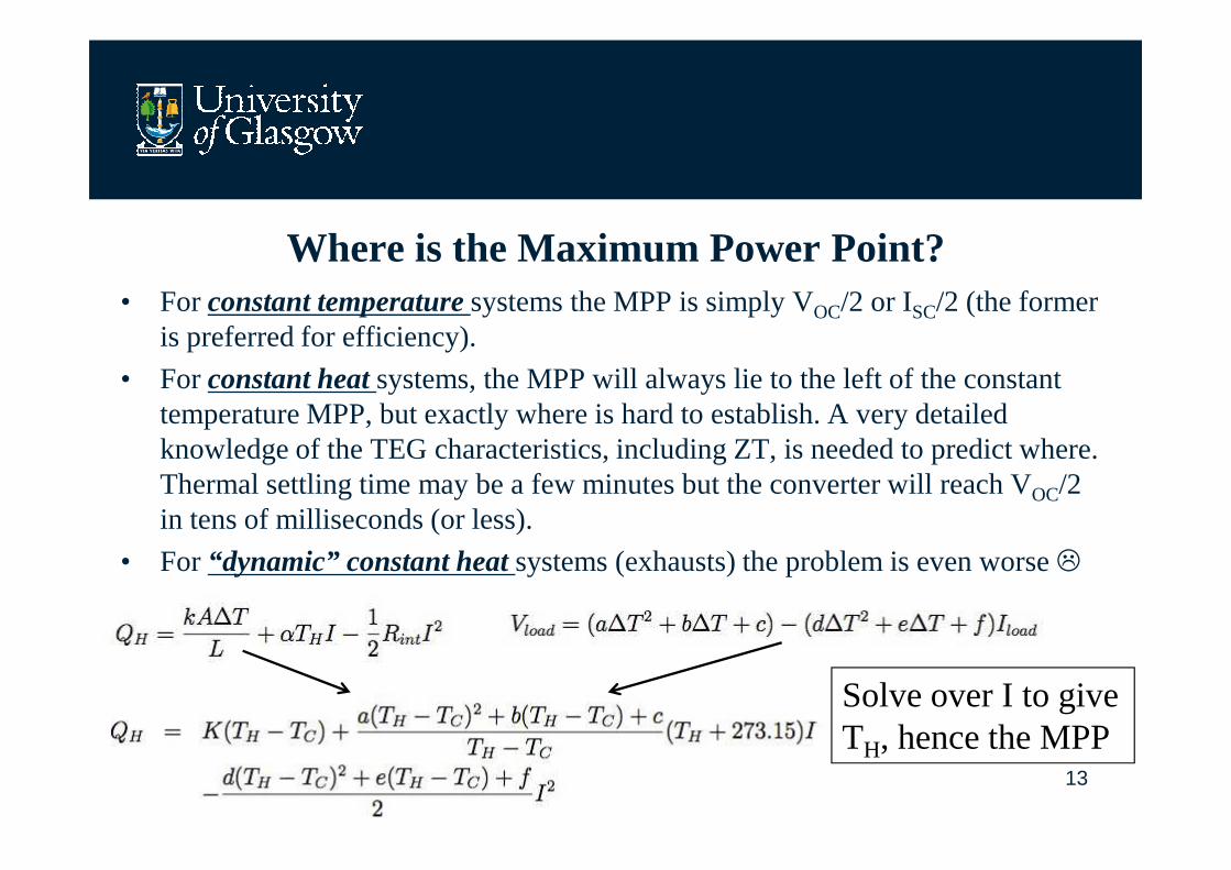
Where is the Maximum Power Point?• For constant temperature systems the MPP is simply VOC/2 or ISC/2 (the former
is preferred for efficiency).
• For constant heat systems, the MPP will always lie to the left of the constant temperature MPP, but exactly where is hard to establish. A very detailed knowledge of the TEG characteristics, including ZT, is needed to predict where.
13
knowledge of the TEG characteristics, including ZT, is needed to predict where. Thermal settling time may be a few minutes but the converter will reach VOC/2 in tens of milliseconds (or less).
• For “dynamic” constant heat systems (exhausts) the problem is even worse �
Solve over I to give TH, hence the MPP
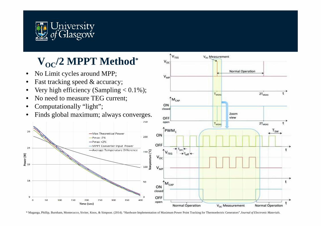
VOC/2 MPPT Method*
• No Limit cycles around MPP;• Fast tracking speed & accuracy;• Very high efficiency (Sampling < 0.1%);• No need to measure TEG current;• Computationally “light”;• Finds global maximum; always converges.
14
• Finds global maximum; always converges.
* Maganga, Phillip, Burnham, Montecucco, Siviter, Knox, & Simpson. (2014). “Hardware Implementation of Maximum Power Point Tracking for Thermoelectric Generators”.Journal of Electronic Materials.
Considerations for automotive MPP converters• The vehicle has a battery => the converter can appear as a current source
on the +12V (or +24V) rail;
• Output voltage regulation is not needed;
• Multiple converters needed for large TEG arrays due to variable intra-
15
• Multiple converters needed for large TEG arrays due to variable intra-array operating temperatures; (parallel output current sources)
• Low-power cut-off determined by voltage step-up or step-down factor (extreme converter duty cycle reduces efficiency);
• Simple PWM control of input impedance sets MPP for TEGs;
• Buck-boost topology gives ~3V � 50V input voltage range (@12V out);
• Converter efficiency ~ 95% can be realised at optimum output power;
• “Sweet spot” is ~ 50W per converter for size, cost, weight, etc.
• Fairly easy integration with vehicle data & communications bus
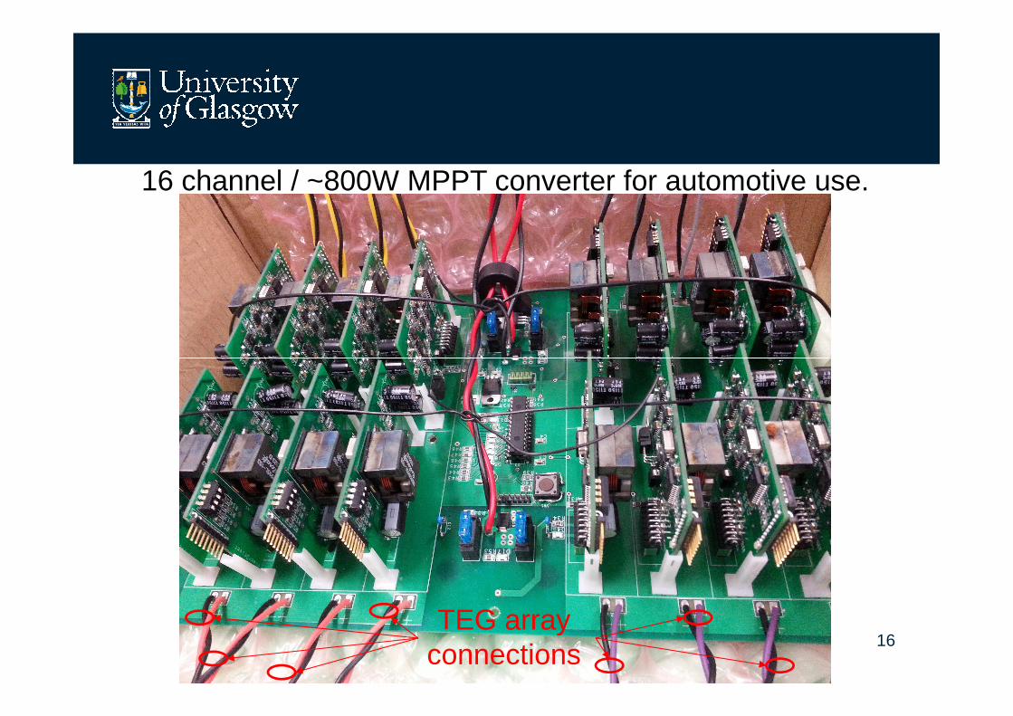
16 channel / ~800W MPPT converter for automotive use.
16TEG array
connections
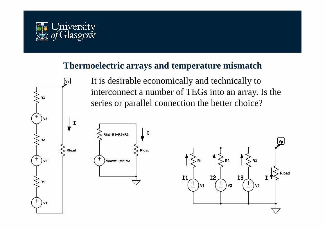
Thermoelectric arrays and temperature mismatch
It is desirable economically and technically to interconnect a number of TEGs into an array. Is the series or parallel connection the better choice?
17
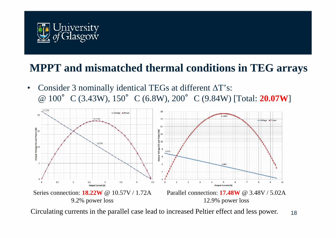
MPPT and mismatched thermal conditions in TEG arrays
• Consider 3 nominally identical TEGs at different ∆T’s:@ 100°C (3.43W), 150°C (6.8W), 200°C (9.84W) [Total: 20.07W]
18
Series connection: 18.22W @ 10.57V / 1.72A9.2% power loss
Parallel connection: 17.48W @ 3.48V / 5.02A12.9% power loss
Circulating currents in the parallel case lead to increased Peltier effect and less power.
Implications for variable flow exhaust gas TEG systems• Large TEG pellet cross-sectional area / low #couples produces a lower
voltage / higher current electrical output, which leads to:– An increased parasitic Peltier effect, which leads to:
– A lower module ∆T and higher heat exchanger ∆T, which leads to:
– Lower TEG power delivery and a higher vehicle heat load.
19
– Lower TEG power delivery and a higher vehicle heat load.
– AND more TEGs needed per array to ease converter design, which leads to:• Increased losses in the array due to temperature mismatch;
• Increased I2R losses in the wiring and converters;
• Increased use of Tellurium (reduced efficiency) and increased mass & cost;
– AND the problem of finding the MPP is exacerbated due to variable ΘTEG
• Current simulation tools are apparently misleading the designer:– Substituting “optimised” TEG modules with a small TEG pellet cross-
sectional area in an extant design resulted in a significant power output increase when using the same heat source and the same heat exchangers.
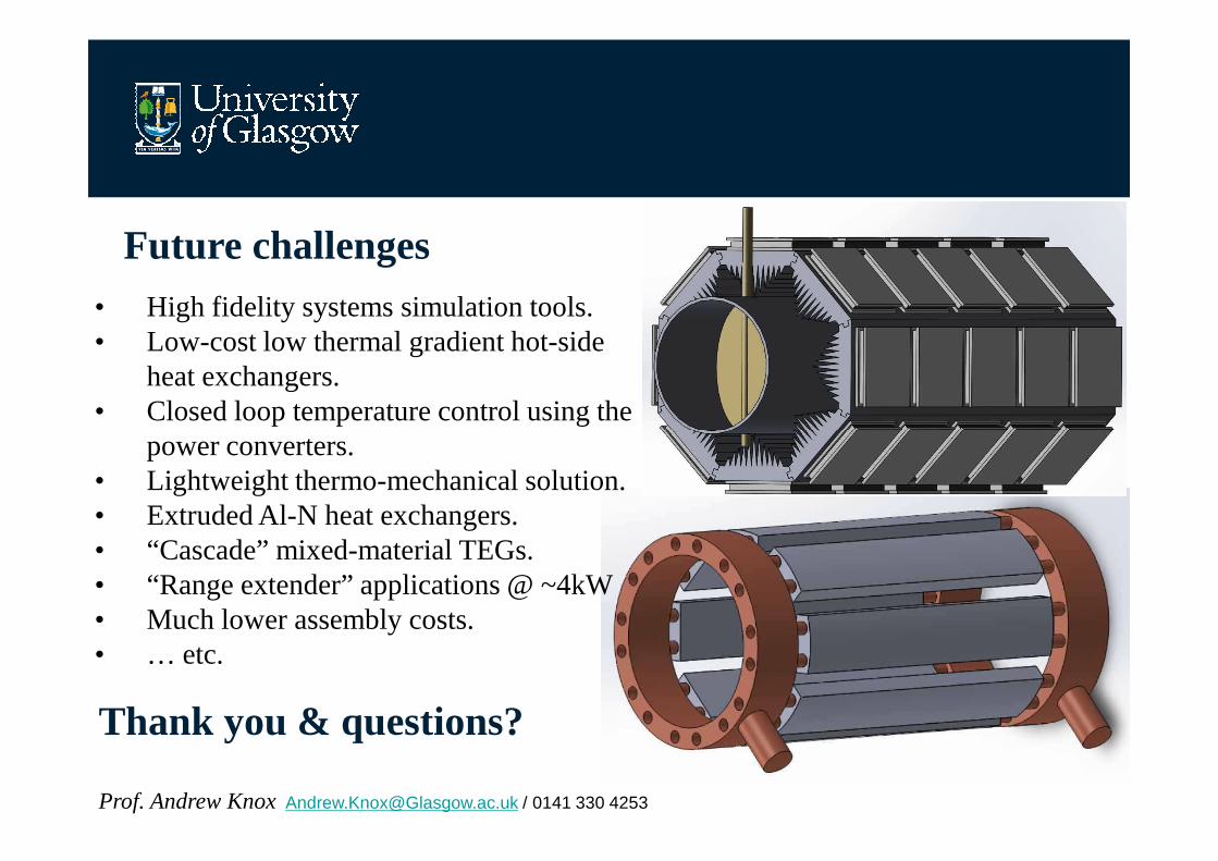
Future challenges• High fidelity systems simulation tools.• Low-cost low thermal gradient hot-side
heat exchangers.• Closed loop temperature control using the
power converters.
20
power converters.• Lightweight thermo-mechanical solution.• Extruded Al-N heat exchangers.• “Cascade” mixed-material TEGs.• “Range extender” applications @ ~4kW• Much lower assembly costs.• … etc.
Thank you & questions?
Prof. Andrew Knox [email protected] / 0141 330 4253
![Manchester Practical [وضع التوافق]](https://static.fdocument.org/doc/165x107/556e0fb4d8b42aba5d8b5162/manchester-practical-.jpg)
![BCH303 [Practical]](https://static.fdocument.org/doc/165x107/61ee1f09d9e6b431aa0abd95/bch303-practical.jpg)