Today in Precalculus Go over homework Notes: Graphs of Polar Equations Homework.
Physics 505 Fall 2005
Homework Assignment #11 — Solutions
Textbook problems: Ch. 7: 7.3, 7.5, 7.8, 7.16
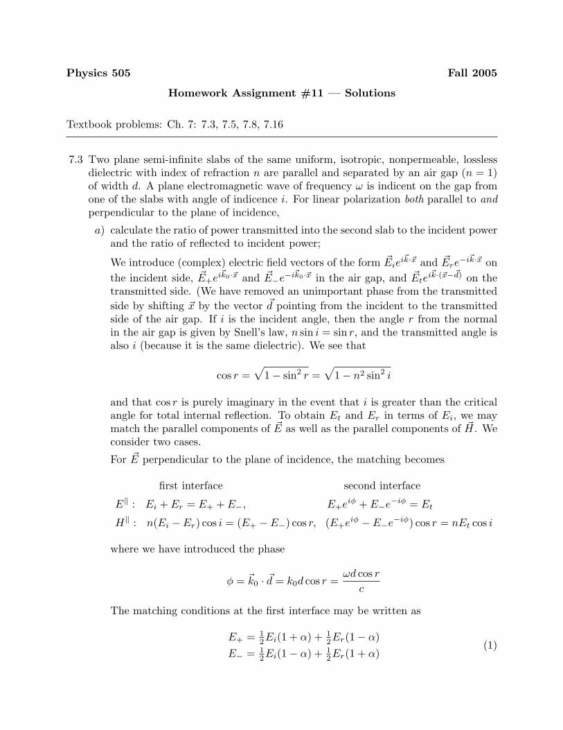
7.3 Two plane semi-infinite slabs of the same uniform, isotropic, nonpermeable, losslessdielectric with index of refraction n are parallel and separated by an air gap (n = 1)of width d. A plane electromagnetic wave of frequency ω is indicent on the gap fromone of the slabs with angle of indicence i. For linear polarization both parallel to andperpendicular to the plane of incidence,
a) calculate the ratio of power transmitted into the second slab to the incident powerand the ratio of reflected to incident power;
We introduce (complex) electric field vectors of the form ~Eiei~k·~x and ~Ere
−i~k·~x onthe incident side, ~E+ei~k0·~x and ~E−e−i~k0·~x in the air gap, and ~Ete
i~k·(~x−~d) on thetransmitted side. (We have removed an unimportant phase from the transmittedside by shifting ~x by the vector ~d pointing from the incident to the transmittedside of the air gap. If i is the incident angle, then the angle r from the normalin the air gap is given by Snell’s law, n sin i = sin r, and the transmitted angle isalso i (because it is the same dielectric). We see that
cos r =√
1− sin2 r =√
1− n2 sin2 i
and that cos r is purely imaginary in the event that i is greater than the criticalangle for total internal reflection. To obtain Et and Er in terms of Ei, we maymatch the parallel components of ~E as well as the parallel components of ~H. Weconsider two cases.
For ~E perpendicular to the plane of incidence, the matching becomes
first interface second interface
E‖ : Ei + Er = E+ + E−, E+eiφ + E−e−iφ = Et
H‖ : n(Ei − Er) cos i = (E+ − E−) cos r, (E+eiφ − E−e−iφ) cos r = nEt cos i
where we have introduced the phase
φ = ~k0 · ~d = k0d cos r =ωd cos r
c
The matching conditions at the first interface may be written as
E+ = 12Ei(1 + α) + 1
2Er(1− α)E− = 1
2Ei(1− α) + 12Er(1 + α)
(1)

where we have defined
α =n cos i
cos r=
n cos i√1− n2 sin2 i
Similarly, the matching conditions at the second interface yield
E+ = 12e−iφEt(1 + α)
E− = 12eiφEt(1− α)
(2)
Equating (1) and (2) allows us to solve for the ratios
Et
Ei=
4α
(1 + α)2e−iφ − (1− α)2eiφ=
2α
2α cos φ− i(1 + α2) sinφ
Er
Ei=
(1− α2)(eiφ − e−iφ)(1 + α)2e−iφ − (1− α)2eiφ
=i(1− α2) sinφ
2α cos φ− i(1 + α2) sinφ
(3)
where
α =n cos i√
1− n2 sin2 i, φ =
ωd cos r
c=
ωd√
1− n2 sin2 i
c
So long as i is below the critical angle, both α and φ are real. In this case, thetransmission and reflection coefficients are
T =∣∣∣∣Et
Ei
∣∣∣∣2 =4α2
4α2 cos2 φ + (1 + α2)2 sin2 φ=
4α2
4α2 + (1− α2)2 sin2 φ
R =∣∣∣∣Er
Ei
∣∣∣∣2 =(1− α2)2 sin2 φ
4α2 cos2 φ + (1 + α2)2 sin2 φ=
(1− α2)2 sin2 φ
4α2 + (1− α2)2 sin2 φ
(4)
Note that T + R = 1, as expected. However, this exhibits a classic interferencebehavior, where T oscillates between (2α/(1 + α2))2 and 1 as the number ofwavelengths in the gap vary.
For ~E parallel to the plane of incidence, we find instead the matching conditions
first interface second interface
E‖ : (Ei − Er) cos i = (E+ − E−) cos r, (E+eiφ − E−e−iφ) cos r = Et cos i
H‖ : n(Ei + Er) = (E+ + E−), E+eiφ − E−e−iφ = nEt
These equations have the same structure as the perpendicular case, but withthe index of refraction entering somewhat differently. We find the matchingconditions
n−1E+ = 12Ei(1 + β) + 1
2Er(1− β)
n−1E− = 12Ei(1− β) + 1
2Er(1 + β)
andn−1E+ = 1
2e−iφEt(1 + β)
n−1E− = 12eiφEt(1− β)
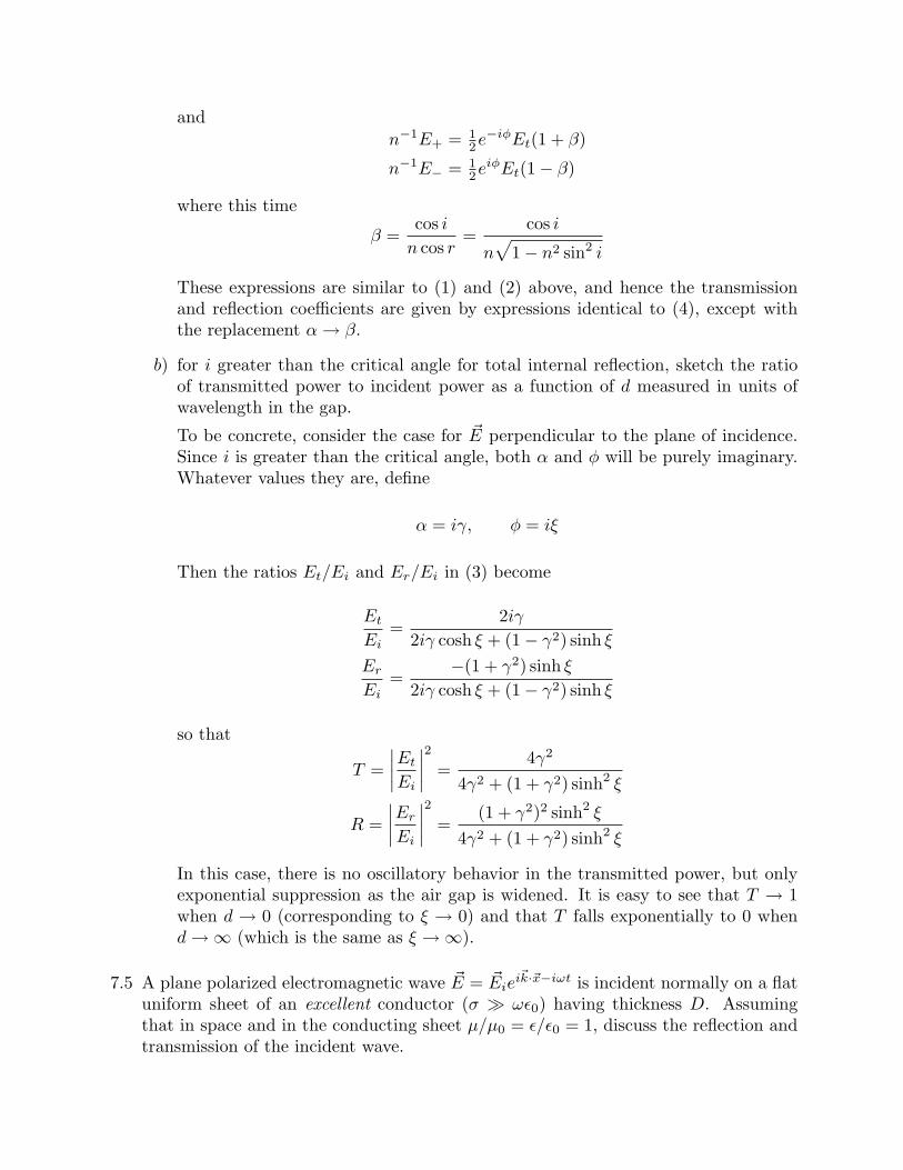
where this time
β =cos i
n cos r=
cos i
n√
1− n2 sin2 i
These expressions are similar to (1) and (2) above, and hence the transmissionand reflection coefficients are given by expressions identical to (4), except withthe replacement α → β.
b) for i greater than the critical angle for total internal reflection, sketch the ratioof transmitted power to incident power as a function of d measured in units ofwavelength in the gap.
To be concrete, consider the case for ~E perpendicular to the plane of incidence.Since i is greater than the critical angle, both α and φ will be purely imaginary.Whatever values they are, define
α = iγ, φ = iξ
Then the ratios Et/Ei and Er/Ei in (3) become
Et
Ei=
2iγ
2iγ cosh ξ + (1− γ2) sinh ξ
Er
Ei=
−(1 + γ2) sinh ξ
2iγ cosh ξ + (1− γ2) sinh ξ
so that
T =∣∣∣∣Et
Ei
∣∣∣∣2 =4γ2
4γ2 + (1 + γ2) sinh2 ξ
R =∣∣∣∣Er
Ei
∣∣∣∣2 =(1 + γ2)2 sinh2 ξ
4γ2 + (1 + γ2) sinh2 ξ
In this case, there is no oscillatory behavior in the transmitted power, but onlyexponential suppression as the air gap is widened. It is easy to see that T → 1when d → 0 (corresponding to ξ → 0) and that T falls exponentially to 0 whend→∞ (which is the same as ξ →∞).
7.5 A plane polarized electromagnetic wave ~E = ~Eiei~k·~x−iωt is incident normally on a flat
uniform sheet of an excellent conductor (σ � ωε0) having thickness D. Assumingthat in space and in the conducting sheet µ/µ0 = ε/ε0 = 1, discuss the reflection andtransmission of the incident wave.
a) Show that the amplitudes of the reflected and transmitted waves, correct to thefirst order in (ε0ω/σ)1/2, are:
Er
Ei=
−(1− e−2λ)(1− e−2λ) + γ(1 + e−2λ)
Et
Ei=
2γe−λ
(1− e−2λ) + γ(1 + e−2λ)
where
γ =
√2ε0ω
σ(1− i) =
ωδ
c(1− i)
λ = (1− i)D/δ
and δ =√
2/ωµσ is the penetration depth.
So long as we treat the conductor as a medium with complex dielectric constant
ε/ε0 = 1 + iσ
ωε0
we may proceed as if everything were a dielectric. Since there are two boundaries,this problem is very much like the above Problem 7.3, except the expressions areeven simpler because of the normal incidence. As above, we introduce electricfield vectors of the form ~Eie
i~k·~x and ~Ere−i~k·~x on the incident side, ~E+ei~k1·~x and
~E−e−i~k1·~x in the conductor, and ~Etei~k·(~x−~D) on the transmitted side. We use
matching for ~E perpendicular to the plane of incidence (which corresponds to asign convention of having all electric fields pointing in the same direction). Inthis case, the matching becomes
first interface second interface
E‖ : Ei + Er = E+ + E−, E+eiφ + E−e−iφ = Et
H‖ : (Ei − Er) = n(E+ − E−), n(E+eiφ − E−e−iφ) = Et
where n is the complex index of refraction
n =√
ε
ε0=
√1 + i
σ
ωε0(5)
and φ is the phase change for going through the dielectric
φ = k1D =ωn
cD =
ωD
c
√1 + i
σ
ωε0(6)
Solving for Et and Er in terms of Ei, we obtain
Et
Ei=
4/n
(1 + 1/n)2e−iφ − (1− 1/n)2eiφ=
4/neiφ
(1 + 1/n2)(1− e2iφ) + 2/n(1 + e2iφ)Er
Ei=
(1− 1/n2)(eiφ − e−iφ)(1 + 1/n)2e−iφ − (1− 1/n)2eiφ
=−(1− 1/n2)(1− e2iφ)
(1 + 1/n2)(1− e2iφ) + 2/n(1 + e2iφ)
which is essentially equivalent to (3), up to redefining α → 1/n. (In fact, thisproblem can easily be generalized for incidence at an arbitrary angle i by taking1/n→ cos i/n cos r.) We now take the limit where this is an excellent conductor,σ/ωε0 � 1. In this case, the index of refraction (5) and phase change (6) may beapproximated by
n ≈√
iσ
ωε0= (1 + i)
√σ
2ε0ω=
2γ
φ =ωD
cn ≈ (1 + i)
ωD
c
√σ
2ε0ω= (1 + i)D
√µ0σω
2= iλ
For |γ| � 1 (equivalent to |n| � 1) we drop terms of O(1/n2) compared to 1 toarrive at
Et
Ei=
2γe−λ
(1− e−2λ) + γ(1 + e−2λ)Er
Ei=
−(1− e−2λ)(1− e−2λ) + γ(1 + e−2λ)
(7)
where we have kept the O(γ) term in the denominator which becomes importantin the limit λ→ 0.
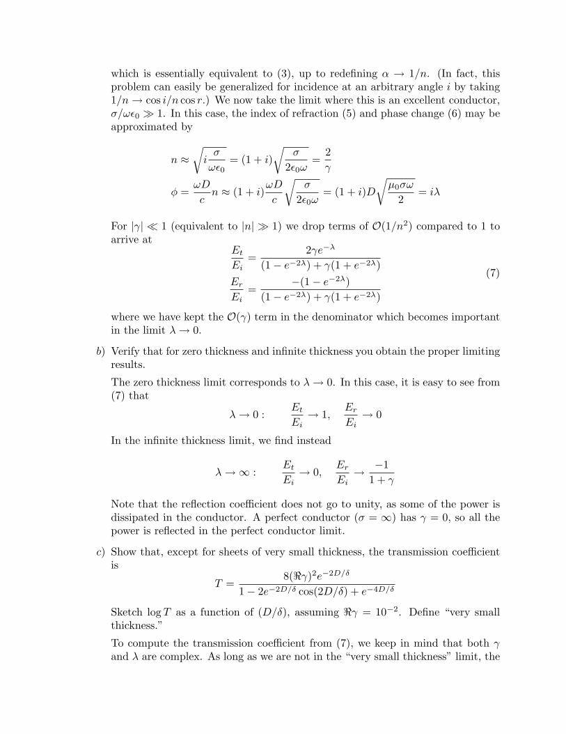
b) Verify that for zero thickness and infinite thickness you obtain the proper limitingresults.
The zero thickness limit corresponds to λ→ 0. In this case, it is easy to see from(7) that
λ→ 0 :Et
Ei→ 1,
Er
Ei→ 0
In the infinite thickness limit, we find instead
λ→∞ :Et
Ei→ 0,
Er
Ei→ −1
1 + γ
Note that the reflection coefficient does not go to unity, as some of the power isdissipated in the conductor. A perfect conductor (σ = ∞) has γ = 0, so all thepower is reflected in the perfect conductor limit.
c) Show that, except for sheets of very small thickness, the transmission coefficientis
T =8(<γ)2e−2D/δ
1− 2e−2D/δ cos(2D/δ) + e−4D/δ
Sketch log T as a function of (D/δ), assuming <γ = 10−2. Define “very smallthickness.”
To compute the transmission coefficient from (7), we keep in mind that both γand λ are complex. As long as we are not in the “very small thickness” limit, the
O(γ) term in the denominator can be ignored. In this case
Et
Ei≈ 2γe−λ
(1− e−2λ)
so that
T =∣∣∣∣Et
Ei
∣∣∣∣2 =4|γ|2e−2<λ
1− 2<(e−2λ) + e−4<λ
Taking |γ|2 = 2(<γ)2 as well as e−2λ = e2iD/δe−2D/δ then gives
T =8(<γ)2e−2D/δ
1− 2e−2D/δ cos(2D/δ) + e−4D/δ
The very small thickness limit corresponds to when the O(γ) term becomes im-portant. This occurs when
|1− e−2λ| ' |γ(1 + e−2λ)|
Expanding for small λ yields
|2λ| ' |2γ| ⇒ D
δ' ωδ
c
Hence small thicknesses correspond to
D <ωδ2
c
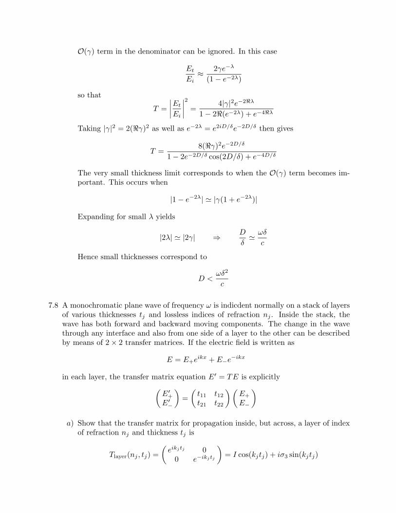
7.8 A monochromatic plane wave of frequency ω is indicdent normally on a stack of layersof various thicknesses tj and lossless indices of refraction nj . Inside the stack, thewave has both forward and backward moving components. The change in the wavethrough any interface and also from one side of a layer to the other can be describedby means of 2× 2 transfer matrices. If the electric field is written as
E = E+eikx + E−e−ikx
in each layer, the transfer matrix equation E′ = TE is explicitly(E′
+
E′−
)=
(t11 t12t21 t22
) (E+
E−
)a) Show that the transfer matrix for propagation inside, but across, a layer of index
of refraction nj and thickness tj is
Tlayer(nj , tj) =(
eikjtj 00 e−ikjtj
)= I cos(kjtj) + iσ3 sin(kjtj)
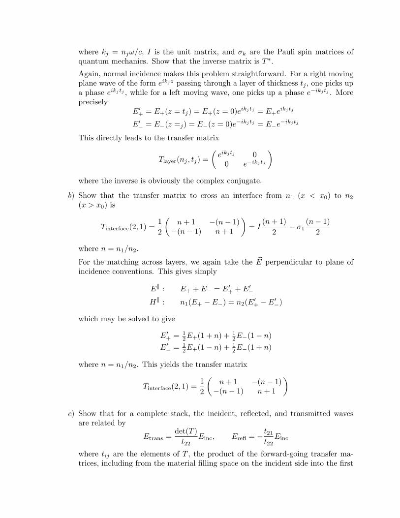
where kj = njω/c, I is the unit matrix, and σk are the Pauli spin matrices ofquantum mechanics. Show that the inverse matrix is T ∗.
Again, normal incidence makes this problem straightforward. For a right movingplane wave of the form eikjz passing through a layer of thickness tj , one picks upa phase eikjtj , while for a left moving wave, one picks up a phase e−ikjtj . Moreprecisely
E′+ = E+(z = tj) = E+(z = 0)eikjtj = E+eikjtj
E′− = E−(z =j) = E−(z = 0)e−ikjtj = E−e−ikjtj
This directly leads to the transfer matrix
Tlayer(nj , tj) =(
eikjtj 00 e−ikjtj
)where the inverse is obviously the complex conjugate.
b) Show that the transfer matrix to cross an interface from n1 (x < x0) to n2
(x > x0) is
Tinterface(2, 1) =12
(n + 1 −(n− 1)−(n− 1) n + 1
)= I
(n + 1)2
− σ1(n− 1)
2
where n = n1/n2.
For the matching across layers, we again take the ~E perpendicular to plane ofincidence conventions. This gives simply
E‖ : E+ + E− = E′+ + E′
−
H‖ : n1(E+ − E−) = n2(E′+ − E′
−)
which may be solved to give
E′+ = 1
2E+(1 + n) + 12E−(1− n)
E′− = 1
2E+(1− n) + 12E−(1 + n)
where n = n1/n2. This yields the transfer matrix
Tinterface(2, 1) =12
(n + 1 −(n− 1)−(n− 1) n + 1
)
c) Show that for a complete stack, the incident, reflected, and transmitted wavesare related by
Etrans =det(T )
t22Einc, Erefl = − t21
t22Einc
where tij are the elements of T , the product of the forward-going transfer ma-trices, including from the material filling space on the incident side into the first

layer and from the last layer into the medium filling the space on the transmittedside.
It ought to be clear that the complete effect of going through several layers is totake a product of transfer matrices. For example
E′ = TE, where T = · · ·T (4, 3)T (n3, t3)T (3, 2)T (n2, t2)T (2, 1)
The transmitted and reflected electric fields are obtained by solving(Et
0
)= T
(Ei
Er
)=
(t11 t12t21 t22
) (Ei
Er
)This gives explicitly
Et = t11Ei + t12Er, 0 = t21Ei + t22Er
which may be solved to obtain
Er = − t21t22
Ei, Et =t11t22 − t12t21
t22Ei =
det(T )t22
Ei
7.16 Plane waves propagate in a homogeneous, nonpermeable, but anisotropic dielectric.The dielectric is characterized by a tensor εij , but if coordinate axes are chosen asthe principle axes, the components of displacement along these axes are related to theelectric-field components by Di = εiEi (i = 1, 2, 3), where εi are the eigenvalues of thematrix εij .
a) Show that plane waves with frequency ω and wave vector ~k must satisfy
~k × (~k × ~E) + µ0ω2 ~D = 0
This is in fact the general Maxwell wave equation, and does not depend on thedetails of the dielectric tensor. This may be derived from the curl equations,using ~∇ → i~k and ∂/∂t → −iω. In a source-free region, the Ampere-Maxwell andFaraday laws give
i~k × ~H = −iω ~D, i~k × ~E − iω ~B = 0
Taking i~k cross Faraday’s law, and using ~B = µ0~H gives
i~k × (i~k × ~E)− iµ0ω(i~k × ~H) = 0
It is then straightforward to substitute in Ampere’s law in the second term toarrive at
~k × (~k × ~E) + µ0ω2 ~D = 0
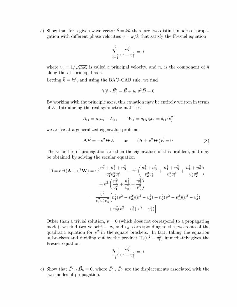
b) Show that for a given wave vector ~k = kn there are two distinct modes of propa-gation with different phase velocities v = ω/k that satisfy the Fresnel equation
3∑i=1
n2i
v2 − v2i
= 0
where vi = 1/√
µ0εi is called a principal velocity, and ni is the component of nalong the ith principal axis.
Letting ~k = kn, and using the BAC–CAB rule, we find
n(n · ~E)− ~E + µ0v2 ~D = 0
By working with the principle axes, this equation may be entirely written in termsof ~E. Introducing the real symmetric matrices
Aij = ninj − δij , Wij = δijµ0εj = δij/v2j
we arrive at a generalized eigenvalue problem
A ~E = −v2W ~E or (A + v2W) ~E = 0 (8)
The velocities of propagation are then the eigenvalues of this problem, and maybe obtained by solving the secular equation
0 = det(A + v2W) = v6 n21 + n2
2 + n23
v21v2
2v23
− v4
(n2
2 + n23
v22v2
3
+n2
1 + n23
v21v2
3
+n2
1 + n22
v21v2
2
)+ v2
(n2
1
v21
+n2
2
v22
+n2
3
v23
)=
v2
v21v2
2v23
[n2
1(v2 − v2
2)(v2 − v23) + n2
2(v2 − v2
1)(v2 − v23)
+ n23(v
2 − v21)(v2 − v2
2)]
Other than a trivial solution, v = 0 (which does not correspond to a propagatingmode), we find two velocities, va and vb, corresponding to the two roots of thequadratic equation for v2 in the square brackets. In fact, taking the equationin brackets and dividing out by the product Πi(v2 − v2
i ) immediately gives theFresnel equation ∑
i
n2i
v2 − v2i
= 0
c) Show that ~Da · ~Db = 0, where ~Da, ~Db are the displacements associated with thetwo modes of propagation.
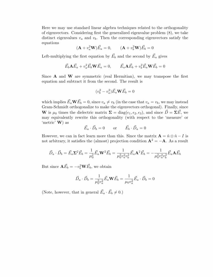
Here we may use standard linear algebra techniques related to the orthogonalityof eigenvectors. Considering first the generalized eigenvalue problem (8), we takedistinct eigenvalues va and vb. Then the corresponding eigenvectors satisfy theequations
(A + v2aW) ~Ea = 0, (A + v2
bW) ~Eb = 0
Left-multiplying the first equation by ~Eb and the second by ~Ea gives
~EbA ~Ea + v2a~EbW ~Ea = 0, ~EaA ~Eb + v2
b~EaW ~Eb = 0
Since A and W are symmetric (real Hermitian), we may transpose the firstequation and subtract it from the second. The result is
(v2b − v2
a) ~EaW ~Eb = 0
which implies ~EaW ~Eb = 0, since va 6= vb (in the case that va = vb, we may insteadGram-Schmidt orthogonalize to make the eigenvectors orthogonal). Finally, sinceW is µ0 times the dielectric matrix Σ = diag(ε1, ε2, ε3), and since ~D = Σ ~E, wemay equivalently rewrite this orthogonality (with respect to the ‘measure’ or‘metric’ W) as
~Ea · ~Db = 0 or ~Eb · ~Da = 0
However, we can in fact learn more than this. Since the matrix A = n⊗ n− I isnot arbitrary, it satisfies the (almost) projection condition A2 = −A. As a result
~Da · ~Db = ~EaΣ2 ~Eb =1µ2
0
~EaW2 ~Eb =1
µ20v
2av2
b
~EaA2 ~Eb = − 1µ2
0v2av2
b
~EaA ~Eb
But since A ~Eb = −v2bW ~Eb, we obtain
~Da · ~Db =1
µ20v
2a
~EaW ~Eb =1
µ0v2a
~Ea · ~Db = 0
(Note, however, that in general ~Ea · ~Eb 6= 0.)