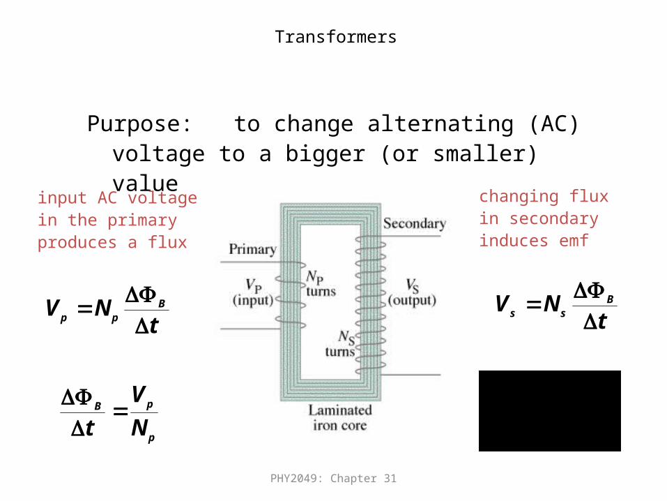
PHY2049: Chapter 31 Transformers Purpose: to change alternating (AC) voltage to a bigger (or...
23
PHY2049: Chapter 31 Transformers Purpose: to change alternating (AC) voltage to a bigger (or smaller) value t N V B p p t N V B s s p p B N V t input AC voltage in the primary produces a flux changing flux in secondary induces emf p s p s N N V V
-
Upload
carmel-opal-sherman -
Category
Documents
-
view
222 -
download
0
Transcript of PHY2049: Chapter 31 Transformers Purpose: to change alternating (AC) voltage to a bigger (or...
PHY2049: Chapter 31
Transformers
Purpose: to change alternating (AC) voltage to a bigger (or smaller) value
tNV B
pp
tNV B
ss
p
pB
N
V
t
input AC voltagein the primaryproduces a flux
changing fluxin secondaryinduces emf
p
sps NN
VV

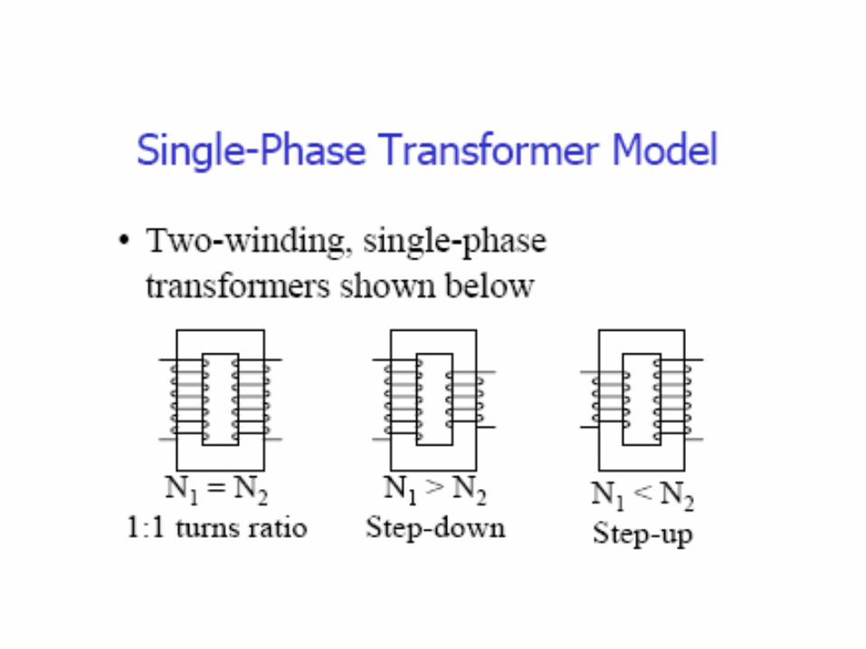
Principle of Transformer Action
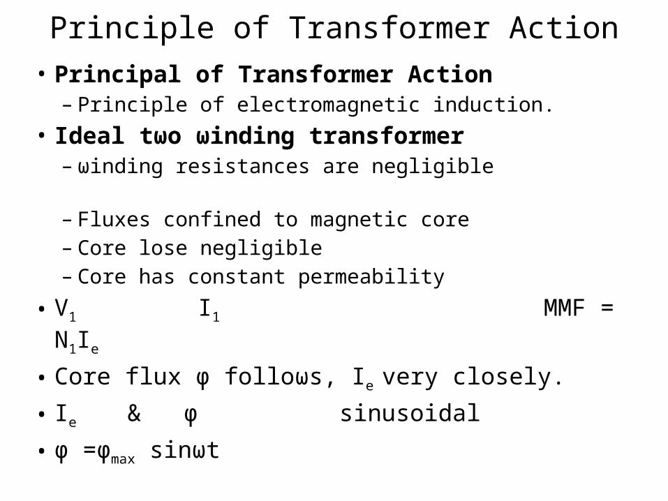
Principle of Transformer Action• Principal of Transformer Action
– Principle of electromagnetic induction.• Ideal tωo ωinding transformer
– ωinding resistances are negligible – Fluxes confined to magnetic core – Core lose negligible – Core has constant permeability
• V1 I1 MMF = N1Ie
• Core flux φ folloωs, Ie very closely.
• Ie & φ sinusoidal
• φ =φmax sinωt
1 1 1 max 1 max
1max 1 max
1 1max
1max 1 max1 1 max 1 max
2 2 2 max 2 max
2max 2 max2
2
cos sin2
sin2
2 4.4432 2
cos sin2
22 2
RMS
RMS
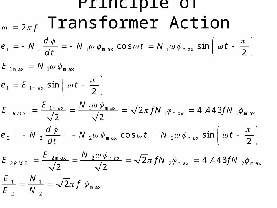
f
de N N t N t
dt
E N
e E t
E NE fN fN
de N N t N t
dt
E NE
2 max 2 max
1 1max
2 2
4.443
2
fN fN
E Nf
E N
Principle of Transformer Action

Transformers
• Nothing comes for free, however!– Increase in voltage comes at the cost of current.– Output power cannot exceed input power!– power in = power out
sspp VIVI
s
p
s
p
p
s
N
N
V
V
II
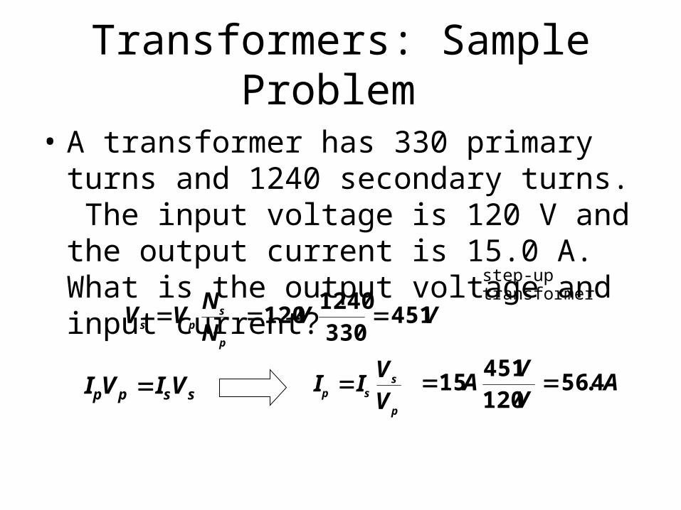
Transformers: Sample Problem
• A transformer has 330 primary turns and 1240 secondary turns. The input voltage is 120 V and the output current is 15.0 A. What is the output voltage and input current?
p
sps NN
VV VV 4513301240
120
step-up transformer
sspp VIVI p
ssp VV
II AVV
A 456120451
15 .


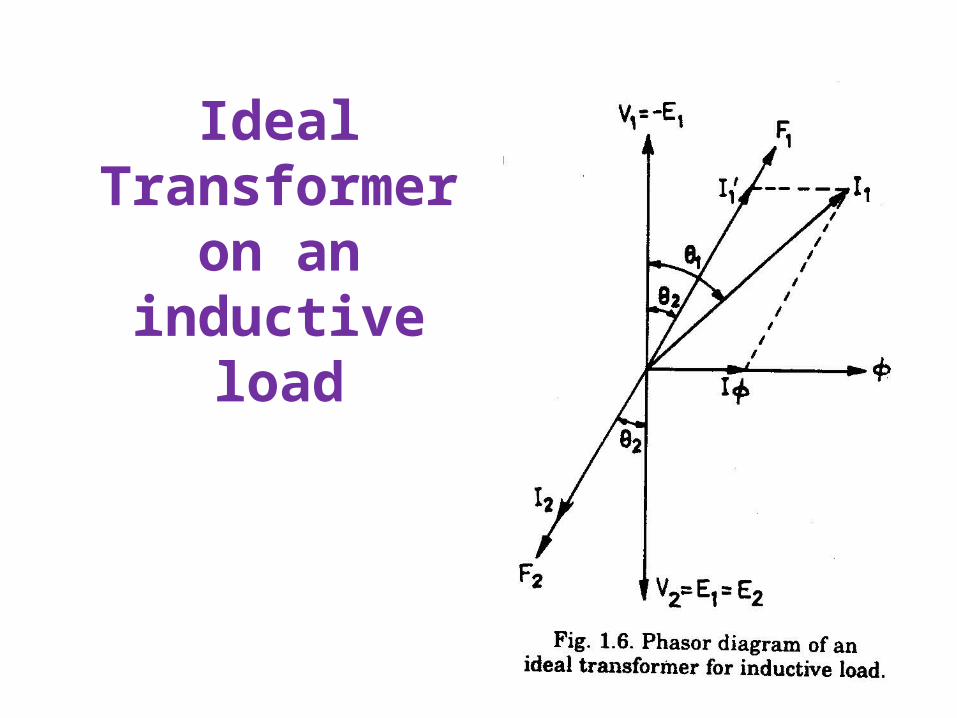
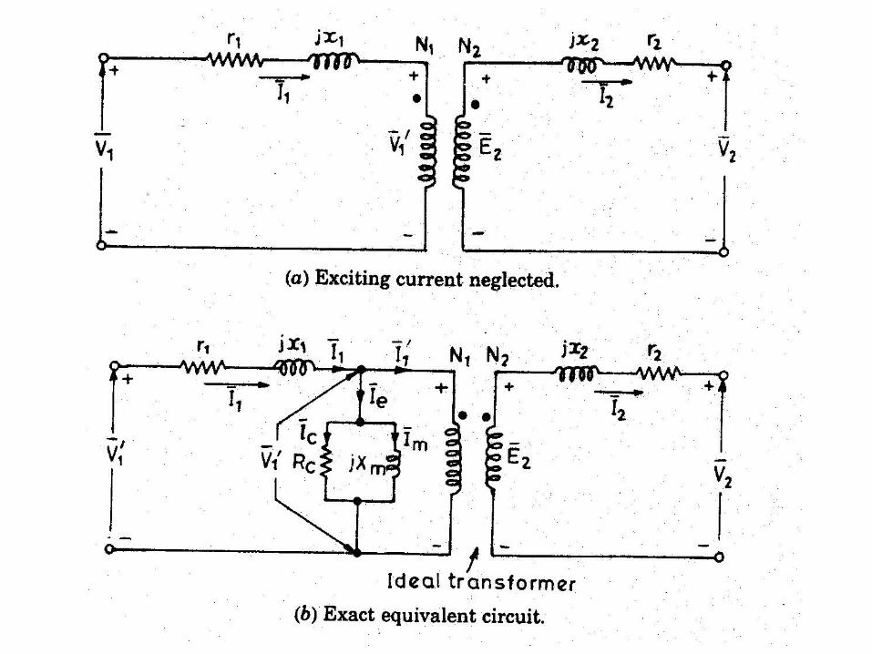
Ideal Transformer on an inductive
load

• The exciting current leads the flux by hysteretic angle,

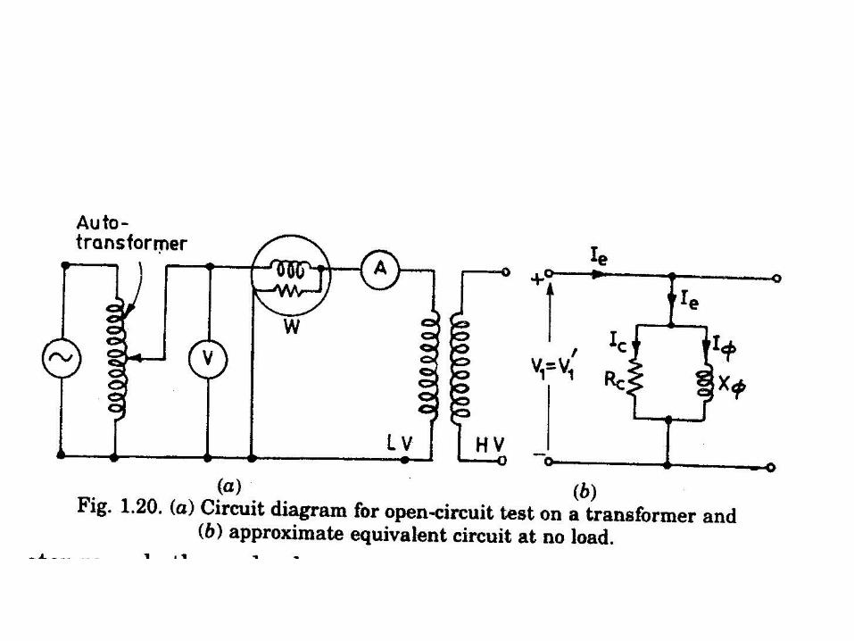
Transformer on LOAD

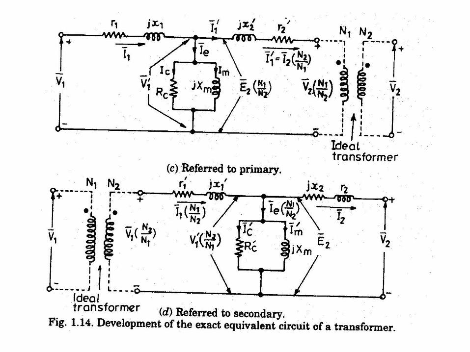
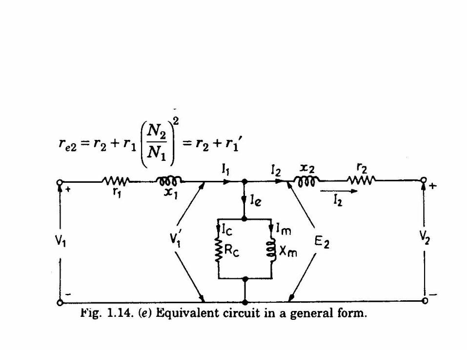
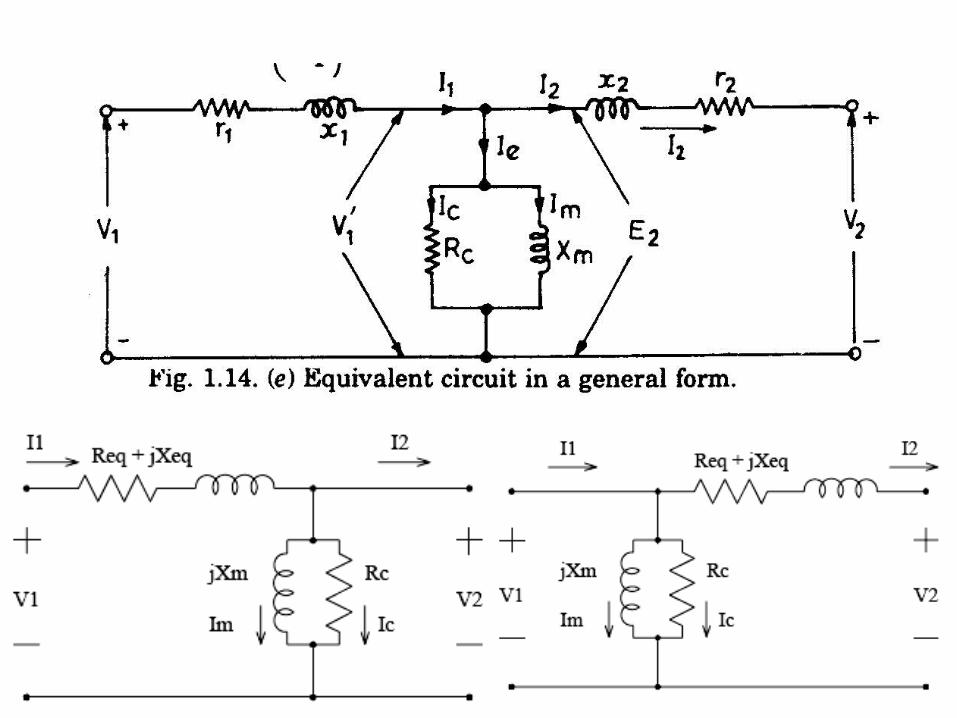
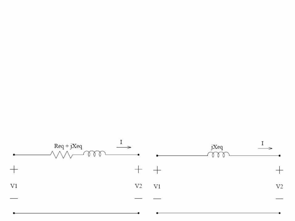
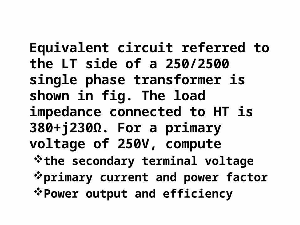
Equivalent circuit referred to the LT side of a 250/2500 single phase transformer is shown in fig. The load impedance connected to HT is 380+j230Ω. For a primary voltage of 250V, computethe secondary terminal voltageprimary current and power factorPower output and efficiency
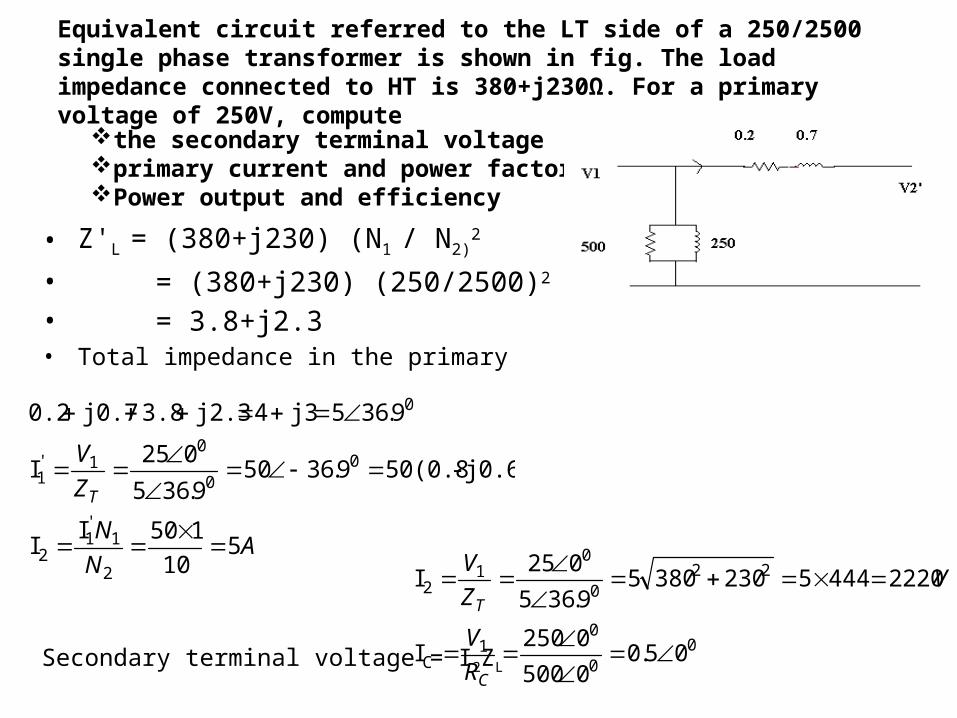
Equivalent circuit referred to the LT side of a 250/2500 single phase transformer is shown in fig. The load impedance connected to HT is 380+j230Ω. For a primary voltage of 250V, compute
• Z'L = (380+j230) (N1 / N2)2
• = (380+j230) (250/2500)2
• = 3.8+j2.3• Total impedance in the primary
Secondary terminal voltage = I2ZL
the secondary terminal voltageprimary current and power factorPower output and efficiency
AN
N
Z
V
T
510
150II
j0.6)-50(0.89.36509.365
025I
9.365 j34 j2.33.8 j0.70.2
2
1'1
2
00
01'
1
0
00
01
C
220
01
2
05.00500
0250I
2220444523038059.365
025I
C
T
R
V
VZ
V

Im= V1/jXm = 250∟0°/250∟90° =1∟-90° =0-j1
I'e = Ic + Im = 0.5+ (0-j1) = 0.5-j1I'1= I'1 +I‘e = 40- j30+0.5- j1= 51∟-37.4°
b) Primary current I1 = 51A
Primary p.f = cosθ1 = cos37.4° = 0.794 lagging
(c) Load p.f• cosθ2 = 380°/ (3802+2302 )= 0.855
• Power Output = V2I2cosθ2 = 2220*5*0.855 = 9500 Watts
• Power Output = I'12RL = 502*3.8 = 9500 Watt
• Core Loss ,PC= v12 / RC = Ic2 RC = 0.52*0.2 =500 Watts
• Power Input = V1I1cosθ1 = 250*51*0.794 = 10123.5