Problem Set 2 - University of Toronto: Electromagnetics … Determine the characteristic impedance...
2
ECE357H1S – ELECTROMAGNETIC FIELDS PROBLEM SET 2 Topics: Time-harmonic behaviour of infinite and finite transmission lines, standing waves, transmission line circuits Reading: Cheng 9-3.1, 9-3.2, 9-4.1, 9-4.2, 9-4.4 1. At a frequency of 4 MHz a parallel wire transmission line has the following parameters: R = 0.025 Ω/m, L = 2 μH/m, G = 0, C = 5.56 pF/m. The line is 100 meters long, terminated in a resistance of 300 Ω. Find the standing wave ratio and voltage reflection coefficient of the load. 2. A 100 km telephone line has a series resistance of 4 Ω/km, an inductance of 3 mH/km, a leakage conductance of 1 μS/km, and a shunt capacitance of 0.015 μF/km, at an angular frequency ω = 5000 rad/s. At the sending end there is a generator supplying 100 volts peak, at 5000 radians per second, in series with a resistance of 300 Ω. The load at the receiving end consists of a 200 Ω resistor. Find the voltage and current as functions of z, and calculate their values at the midpoint of the line, if the load current I L = −0.115 + j0.0268 A. 3. The following characteristics have been measured on a lossy transmission line at 100 MHz: 0 50 0 0.01 dB/m 0.8 rad/m Z j = + Ω = = α β π (a) Determine the attenuation constant of the line in Np/m. Hint: to determine the conversion between dB and Np, consider determining the attenuation constant α for a line that is 1m long that has exactly 1 dB of loss (1 dB/m). (b) Determine R, L, G, and C for the line. 4. A transmission line operating at 125 MHz has Z 0 = 40 Ω, α = 0.02 Np/m, and β = 0.75 rad/m. Find the line parameters R, L, G, and C. 5. Consider a lossless coaxial transmission line having distributed parameters L = 245 nH/m and C = 200 pF/m. The line is terminated with a resistor R L = 100 Ω as shown. The operating frequency is f =1 GHz. UNIVERSITY OF TORONTO FACULTY OF APPLIED SCIENCE AND ENGINEERING The Edward S. Rogers Sr. Department of Electrical and Computer Engineering
Transcript of Problem Set 2 - University of Toronto: Electromagnetics … Determine the characteristic impedance...
ECE357H1S – ELECTROMAGNETIC FIELDS
PROBLEM SET 2
Topics: Time-harmonic behaviour of infinite and finite transmission lines,
standing waves, transmission line circuits
Reading: Cheng 9-3.1, 9-3.2, 9-4.1, 9-4.2, 9-4.4 1. At a frequency of 4 MHz a parallel wire transmission line has the following
parameters: R = 0.025 Ω/m, L = 2 µH/m, G = 0, C = 5.56 pF/m. The line is 100 meters long, terminated in a resistance of 300 Ω. Find the standing wave ratio and voltage reflection coefficient of the load.
2. A 100 km telephone line has a series resistance of 4 Ω/km, an inductance of 3
mH/km, a leakage conductance of 1 µS/km, and a shunt capacitance of 0.015 µF/km, at an angular frequency ω = 5000 rad/s. At the sending end there is a generator supplying 100 volts peak, at 5000 radians per second, in series with a resistance of 300 Ω. The load at the receiving end consists of a 200 Ω resistor. Find the voltage and current as functions of z, and calculate their values at the midpoint of the line, if the load current IL = −0.115 + j0.0268 A.
3. The following characteristics have been measured on a lossy transmission line at
100 MHz:
0 50 00.01 dB/m0.8 rad/m
Z j= + Ω
=
=
α
β π
(a) Determine the attenuation constant of the line in Np/m. Hint: to determine the conversion between dB and Np, consider determining the attenuation constant α for a line that is 1m long that has exactly 1 dB of loss (1 dB/m).
(b) Determine R, L, G, and C for the line. 4. A transmission line operating at 125 MHz has Z0 = 40 Ω, α = 0.02 Np/m, and β =
0.75 rad/m. Find the line parameters R, L, G, and C. 5. Consider a lossless coaxial transmission line having distributed parameters L =
245 nH/m and C = 200 pF/m. The line is terminated with a resistor RL = 100 Ω as shown. The operating frequency is f =1 GHz.
UNIVERSITY OF TORONTO FACULTY OF APPLIED SCIENCE AND ENGINEERING The Edward S. Rogers Sr. Department of Electrical and Computer Engineering
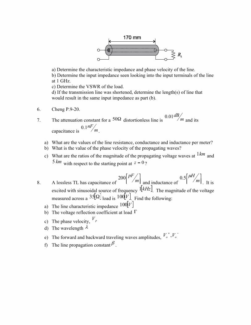
a) Determine the characteristic impedance and phase velocity of the line. b) Determine the input impedance seen looking into the input terminals of the line at 1 GHz. c) Determine the VSWR of the load. d) If the transmission line was shortened, determine the length(s) of line that would result in the same input impedance as part (b).
6. Cheng P.9-20.
7. The attenuation constant for a Ω50 distortionless line is mdB01.0
and its
capacitance is mnF1.0
.
a) What are the values of the line resistance, conductance and inductance per meter? b) What is the value of the phase velocity of the propagating waves? c) What are the ratios of the magnitude of the propagating voltage waves at km1 and
km5 with respect to the starting point at 0=z ?
8. A lossless TL has capacitance of ⎥⎦⎤
⎢⎣⎡
mpF200
and inductance of ⎥⎦⎤
⎢⎣⎡
mHµ5.0
. It is excited with sinusoidal source of frequency [ ]kHz1 . The magnitude of the voltage measured across a [ ]Ω35 load is [ ]V100 . Find the following:
a) The line characteristic impedance [ ]V100 b) The voltage reflection coefficient at load Γ
c) The phase velocity, pV d) The wavelength λ
e) The forward and backward traveling waves amplitudes, −+oo VV ,
f) The line propagation constant β .