Origin of Power Quality Disturbances.pdf
92
Origin of Power Quality Disturbances Zb igniew Leonowicz
Transcript of Origin of Power Quality Disturbances.pdf
Origin of Power Quality Disturbances
Zb igniew Leonowicz
Power Quality Variations
• Voltage Variations– Magnitude– Frequency– Unbalance
• Volatge Fluctuations– Light Flicker
• Waveform Distortion
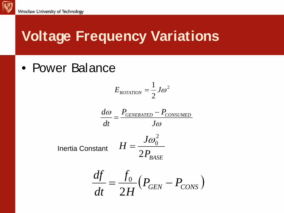
Voltage Frequency Variations
• Power Balance2
21 ωJEROTATION =
ωω
JPP
dtd CONSUMEDGENERATED −=
BASEPJH
2
20ω=Inertia Constant
( )CONSGEN PPHf
dtdf
−=2
0
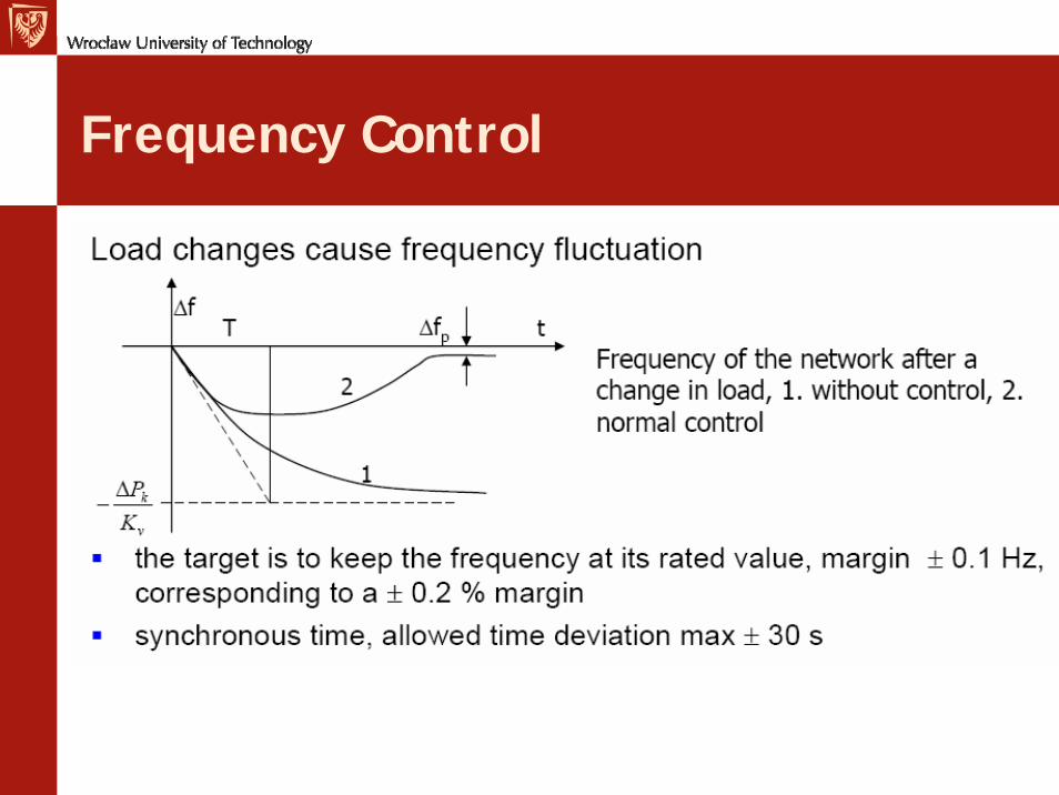
Frequency Control
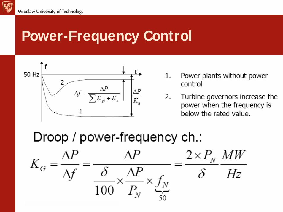
Power-Frequency Control
Kn - Natural power-frequency charcteristics - STIFFNESS
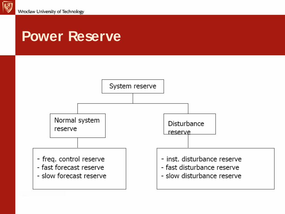
Power Reserve
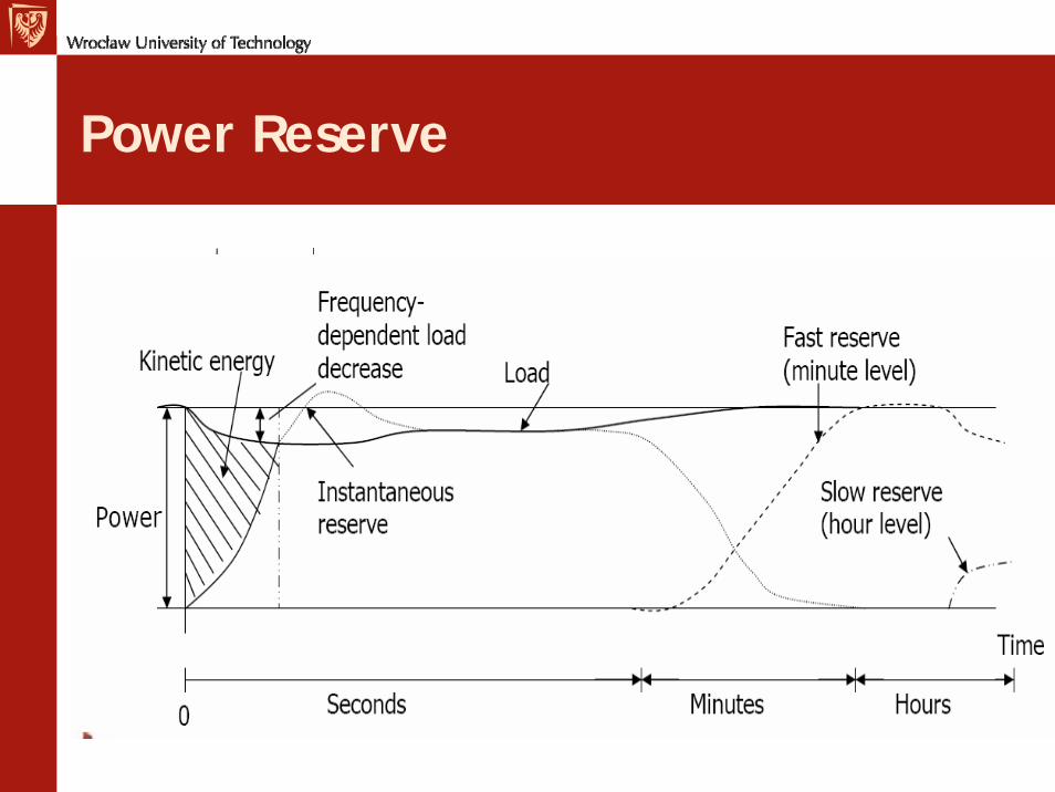
Power Reserve
Power reserve
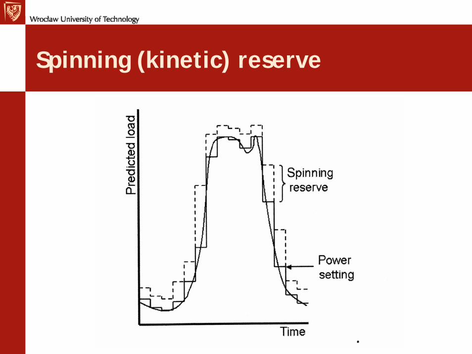
Spinning (kinetic) reserve
Consequences
• Apparently small problems– Time deviation of clocks ?– Motor speed– Variation of magnetic flux?– Underfrequency tripping – largelarge--scale blackoutscale blackout– (49.5 Hz – generator underfrequency relay) – Rate of change of frequency (PLL)– Distributed generation (ROCOF) detect
islanding

Measurements
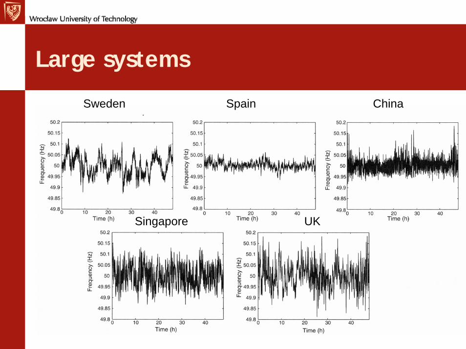
Large systems
Sweden Spain China
Singapore UK
Voltage Magnitude Variations
• Very serious consequences– Insulation failure– Induction motors
• Starting torque, temperature at full-load– Incandescent lamps– Fluorescent lamps– Heating (output, duty cycle)– Electronic equipment– Transformers’ magnetizing current– …..
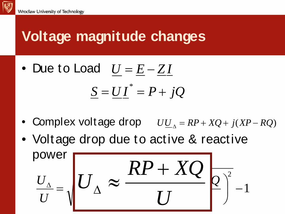
Voltage magnitude changes
• Due to Load
• Complex voltage drop
• Voltage drop due to active & reactive power
IZEU −=
jQPIUS +== *
)( RQXPjXQRPUU −++=Δ
112
2
2
2 −⎟⎠⎞
⎜⎝⎛ −
+⎟⎠⎞
⎜⎝⎛ ++=Δ
URQXP
UXQRP
UU
UXQRPU +
≈Δ

In three-phase system
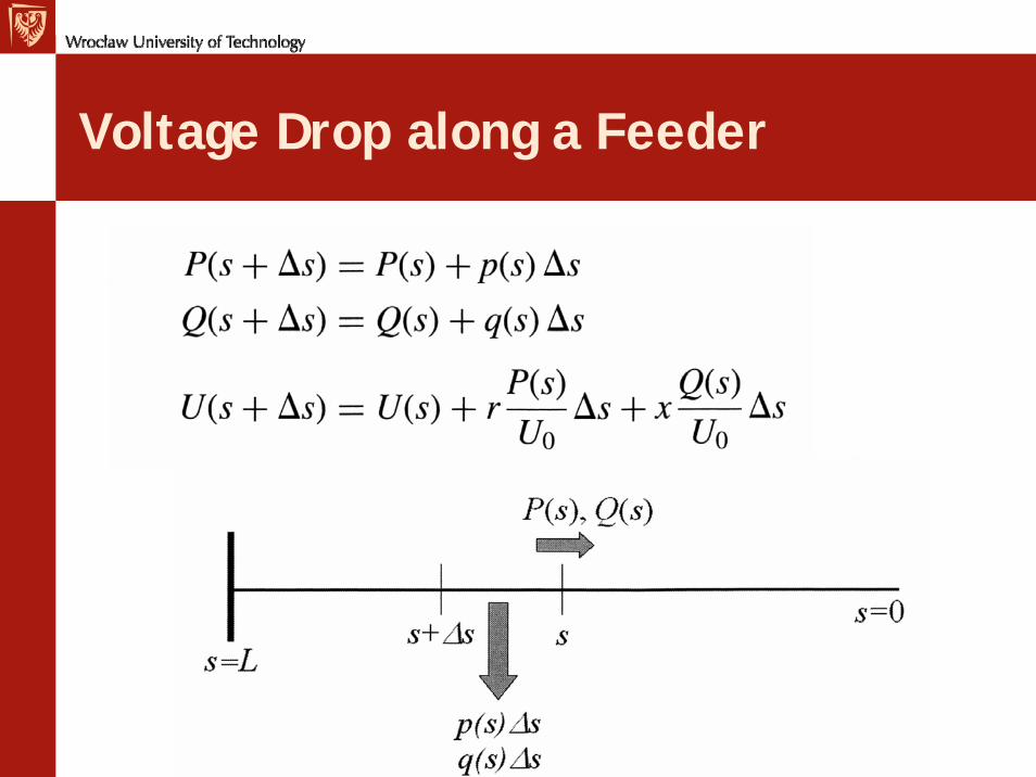
Voltage Drop along a Feeder
Control of Voltage
• Generator Units• Shunt capacitor banks• Series capacitor banks• Shunt reactors• Limiting the length of feeders• Increase of the cross-section• Transformer tap changers• Controllable sources of reactive power (SVCs ,
synchronous machines with no load)
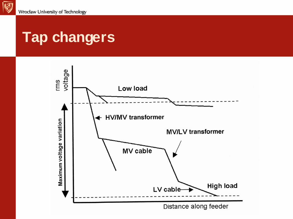
Tap changers
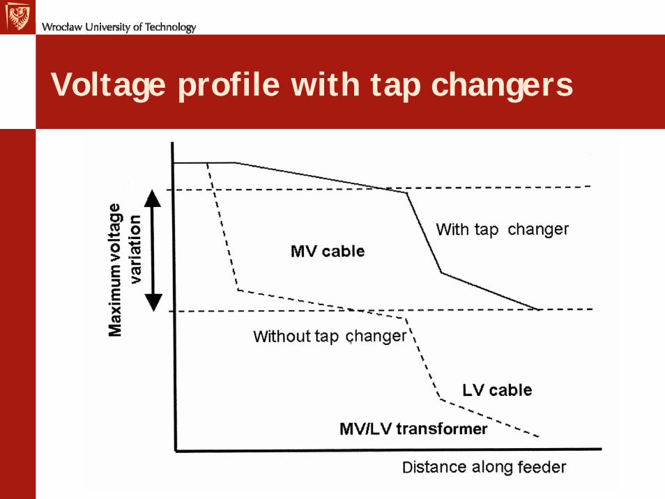
Voltage profile with tap changers

On-load tap changer
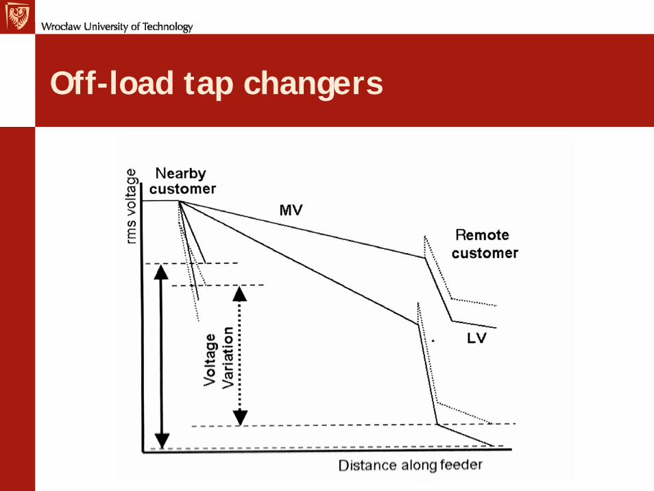
Off-load tap changers
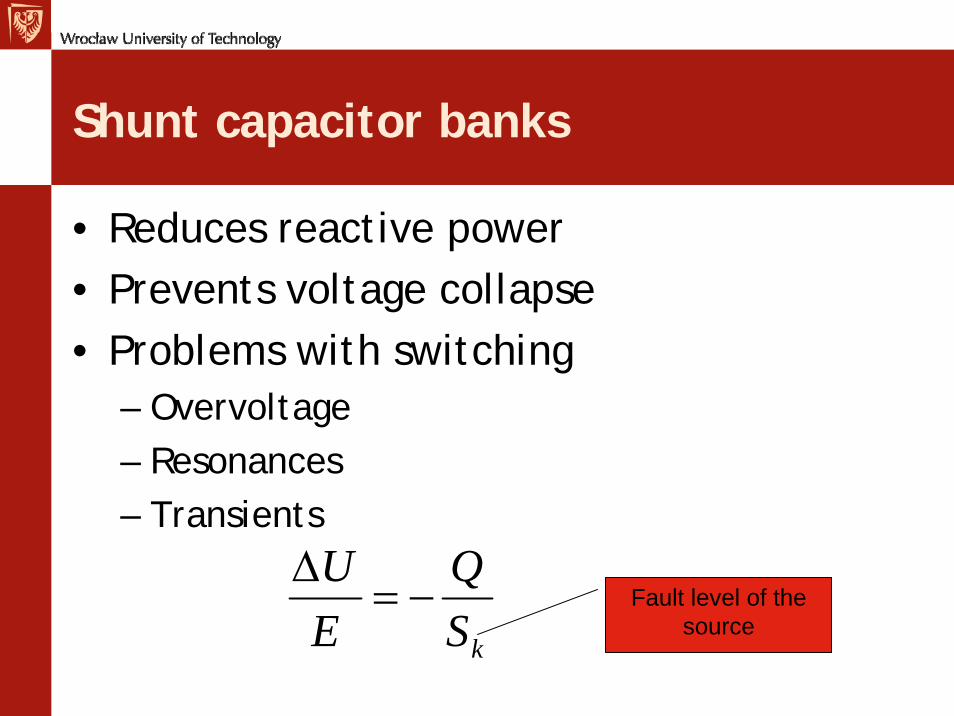
Shunt capacitor banks
• Reduces reactive power• Prevents voltage collapse• Problems with switching
– Overvoltage– Resonances– Transients
kSQ
EU
−=Δ
Fault level of the source
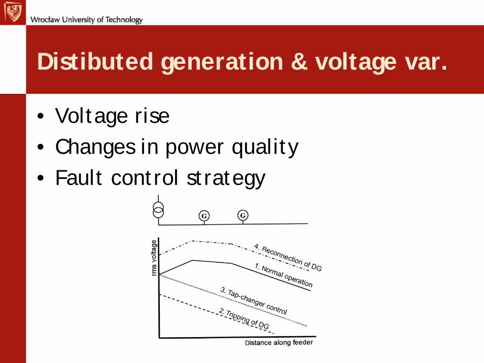
Distibuted generation & voltage var.
• Voltage rise• Changes in power quality• Fault control strategy
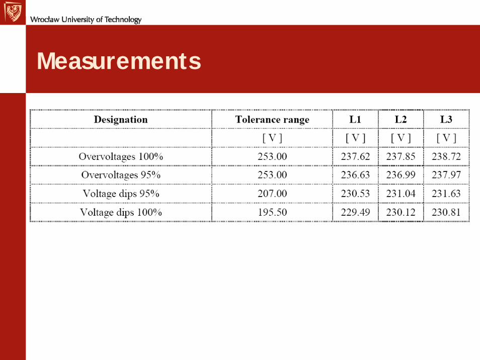
Measurements
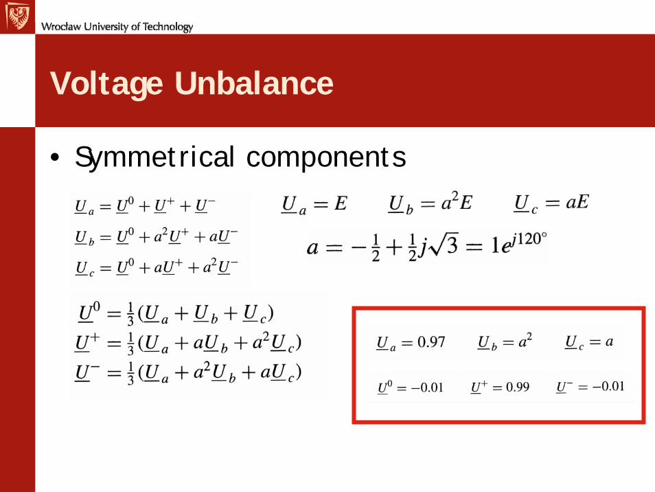
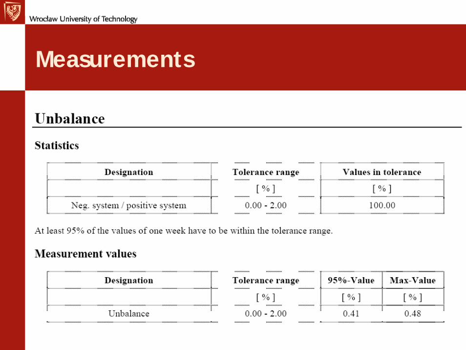
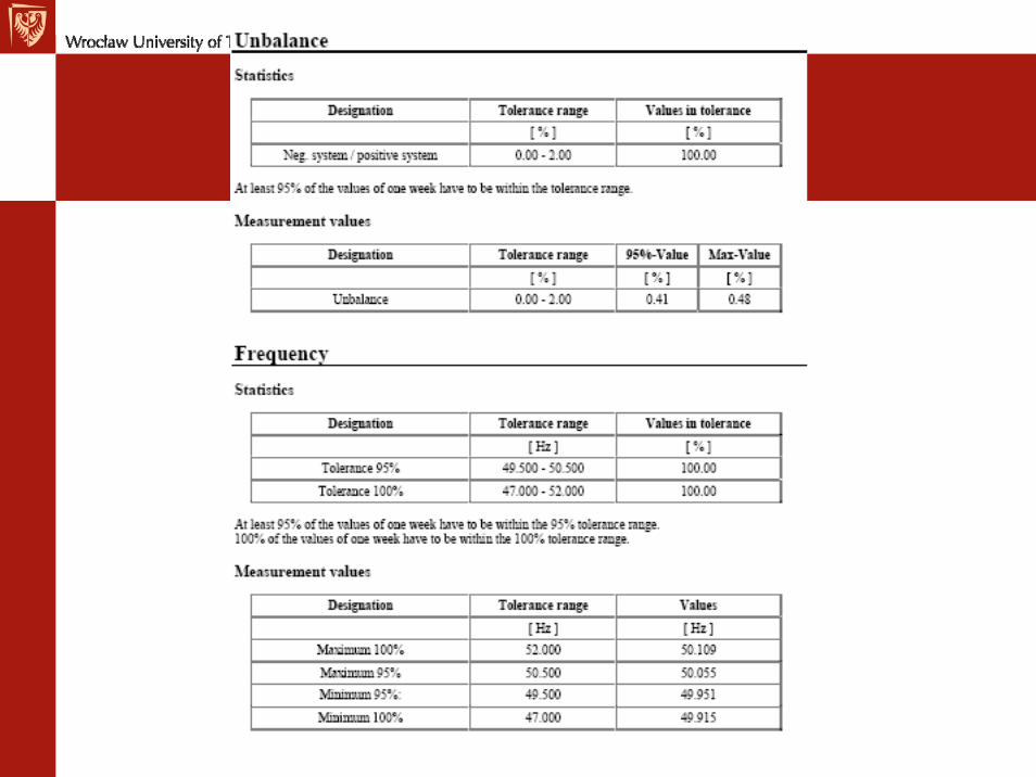
Voltage Unbalance
• Symmetrical components
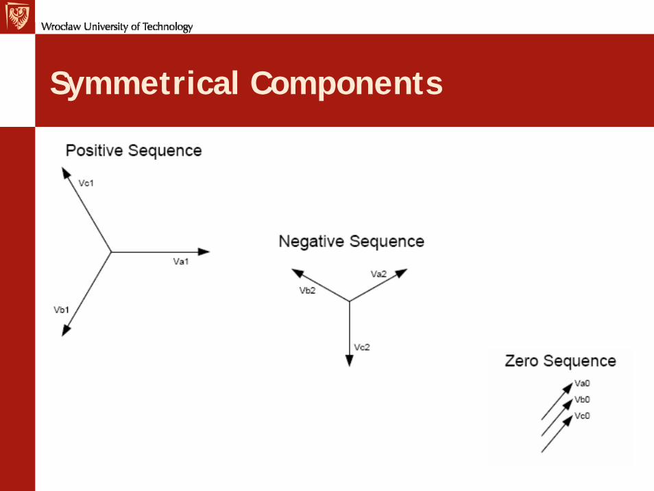
Symmetrical Components
Components
• Positive-sequence voltage– Amount of balanced voltage in unbalanced set
of voltages, power flow from generators to motors
• Negative-sequence voltage– Indicates the amount of unbalance in the
system
• Zero-sequence– Average of three phase voltages
Origin of Unbalance
• Currents– Single-phase loads (LV, MV,HV networks)
• Voltages– Unbalanced impedances
In a three-phase system, voltage unbalance takes place when the magnitudes of phase or line voltages are different and the phase angles differ from the balanced conditions, or both.
Consequences
• Unbalance kills motors and wastes energy• Motors, rectifiers• Uneven load
Measurements
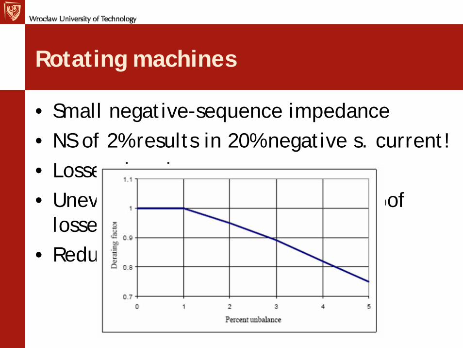
Rotating machines
• Small negative-sequence impedance• NS of 2% results in 20% negative s. current!• Losses, heating• Uneven losses – 1% unbalance=121% of
losses• Reduction of Insulation Life
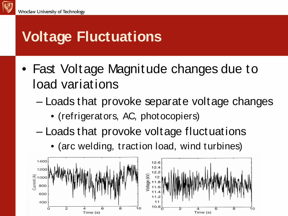
Voltage Fluctuations
• Fast Voltage Magnitude changes due to load variations– Loads that provoke separate voltage changes
• (refrigerators, AC, photocopiers)
– Loads that provoke voltage fluctuations• (arc welding, traction load, wind turbines)
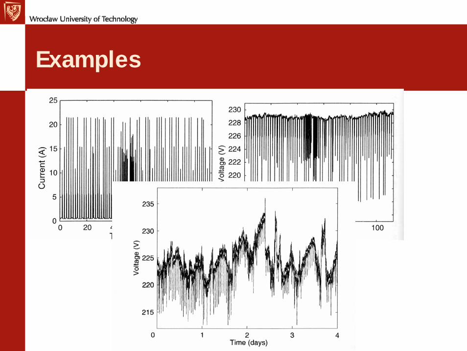
Examples
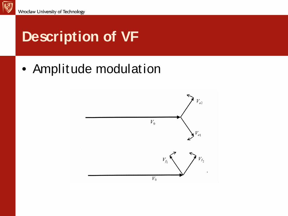
Description of VF
• Amplitude modulation
Light Flicker
• IEEE-100 definitions:• – “A perceptible change in electric light source intensity• due to a fluctuation of input voltage.”• – “A variation of input voltage sufficient in duration to• allow visual observation of a change in electric light• source intensity.”• • In summary• – “Flicker” refers to both: 1) a perceptible change in• electric light intensity, and 2) the voltage variation• responsible for that change in electric light intensity
Norms
Continuous, cyclic, or intermittent
• Continuous or cyclic– Results in voltage modulation or higher
- frequency voltage fluctuations• Intermittent– Occasional voltage variations caused by faults, or motor-startsLow to very low frequencies
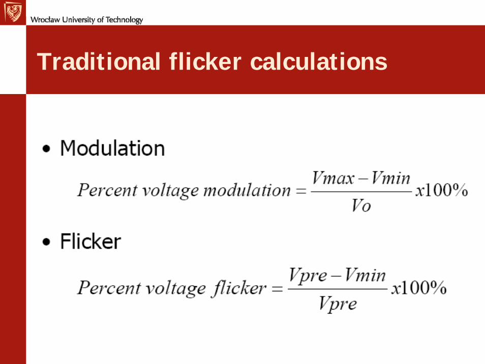
Traditional flicker calculations
New way
• IEEE Std. 1453-2004• – Adopts IEC 61000-4-15 – international flicker
standard as IEEE 1453.• – Employs a special “flickermeter”• – Threshold of irritation is still quite similar to
IEEE-519 or IEEE-141 threshold• – Simplifies pass-fail testing provided the
measuring or analysis tools are available
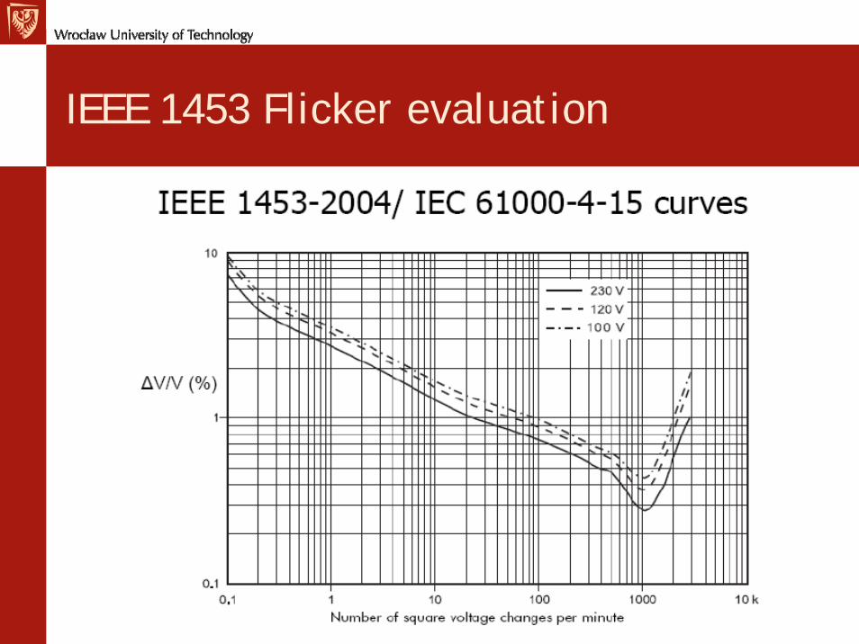
IEEE 1453 Flicker evaluation
IEEE 1453 Flicker evaluation
Standard specifies a flickermeter– Processes voltage measurements to
simulate their effect on incandescent bulbs, and theresponse of the human eye to those effects
– Includes response to multiple flicker events of different magnitudes and frequencies
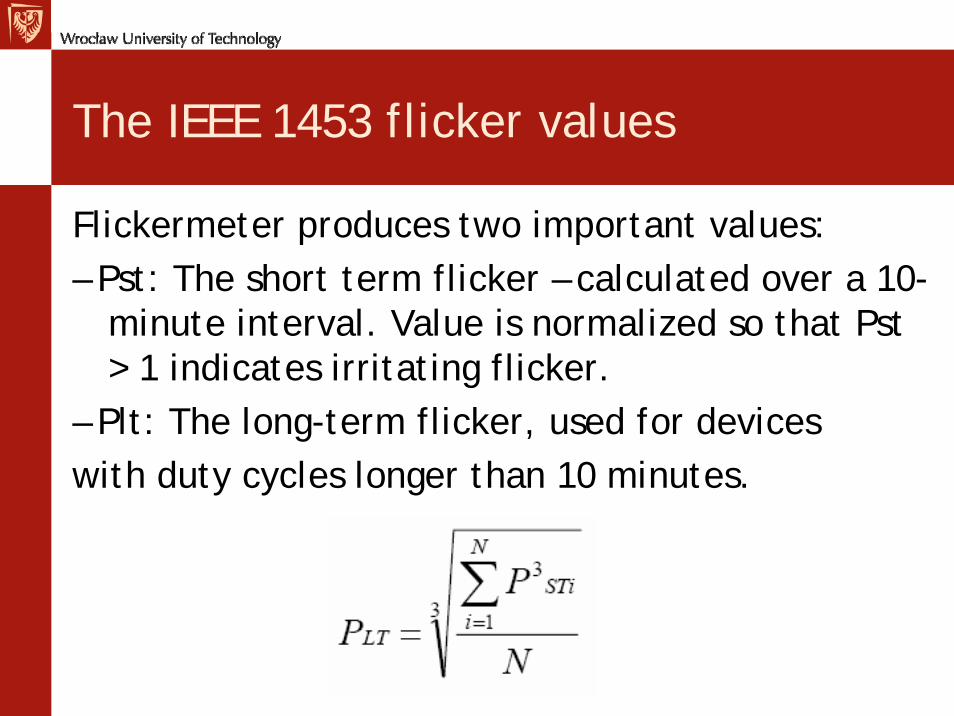
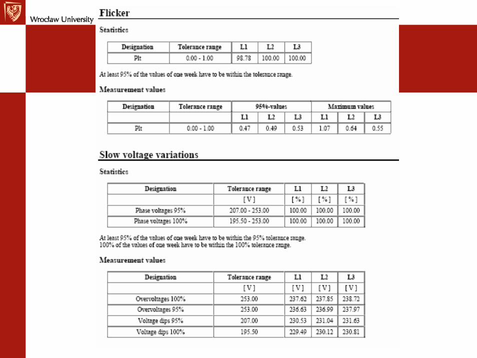
The IEEE 1453 flicker values
Flickermeter produces two important values:– Pst: The short term flicker – calculated over a 10-
minute interval. Value is normalized so that Pst > 1 indicates irritating flicker.
– Plt: The long-term flicker, used for deviceswith duty cycles longer than 10 minutes.
Flicker mitigation
• Address the three conditions– Variable loads• Motor soft-starters or ASDs• Line reactors on arc furnaces• Design specifications in new equipment• Break up the load– Change the lighting• Light output from a CFL flickers about 25% asmuch as that from an incandescent for similarsmall voltage fluctuations
Flicker mitigation
• System impedance/capacity– Reconductor– Larger transformers– Static VAR compensators• Inject reactive power during motor starts• May also correct power factor and filter
harmonics– Thyristor switched capacitors
Flicker mitigation
• Variation frequency– Modify control system –
• Increase bandwidth on pressure, temperature,level, etc.
– Modify mechanical system-• Match equipment to the load• Build “inertia” into the system– Thermal mass– Increased storage of compressed air
Waveform Distortions
• Voltage distortion – Current Distortion• Problems:
– Tripping of Circuit Breaker or Fuse– Transformer overheating– Capacitor fuse tripping, other problems– Malfunction of Electronic Equipment– Overheat of neutral conductors
Transformers
• Audible Noise• Heating (current distortion), stray flux• Hot-spots• Derating
Cables and Lines
• Heating• Skin Effect• Local temperature Rise
Neutral Conductors
• Triple Harmonics add in NC• Dangerous overheating – no protection
Electronic Equipment
• Very difficult to quantify• Zero-crossing algorithms• High-frequency coupling with logic or
electronic circuits –> malfunction– (THD>5%, harmonics >3%)
• Neutral-to-ground voltage• Third harmonic currents• TV screens, fluorescent bulbs
Telephone interference
• Coupling of high-frequency currents• Overhead lines
Capacitors
• Main problem• Current increases with frequency• Overheating and damage• Thermal and dielectric stress• Amplification of harmonic voltage &
current - resonances• Capacitors in Static power converters, EMI
filters
Rotating Machines
• Inductive – current reduces with frequency• Heating, hot-spots• Oscillations of torque• Noise• Single-phase motors -> capacitors,
resonance
Unclear interactions
• Insulation-Corona starting level depends on peak voltage
• Protection- small effects on fuses, old relays react to peak current (not rms)
• Reactance-earthed networks- de-tuning of Petersen coils, increases earth fault current.
• Lighting – complex phenomena
Harmonic Distortion
• Nonsinusoidal but periodic– Even harmonic distortion– Odd harmonic distortion
• Interharmonic Distortion– Non-multiple integer of power system
frequency
• Subharmonic Distortion– < 50 Hz
• Non-Periodic Distortion
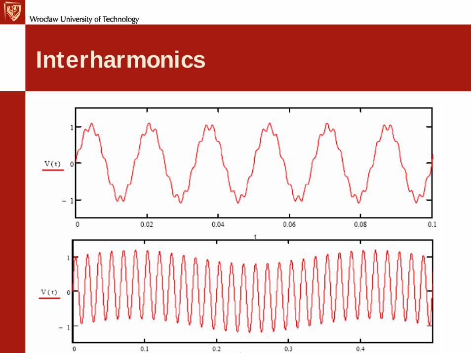
Interharmonics
Sources of interharmonics
Power-line-carrier signalsFrequency convertersDrivesCycloconvertersInduction furnacesArcing loadsLoad variations
Interharmonics issues
Analysis• – Power quality instruments may not accurately
measure themImpacts• – Same heating and distortion issues as regular
harmonics• – Oscillations in mechanical systems• – Interference with power-line-carrier systems• – Tuned filters may not work because of the
variability of the harmonic spectrum
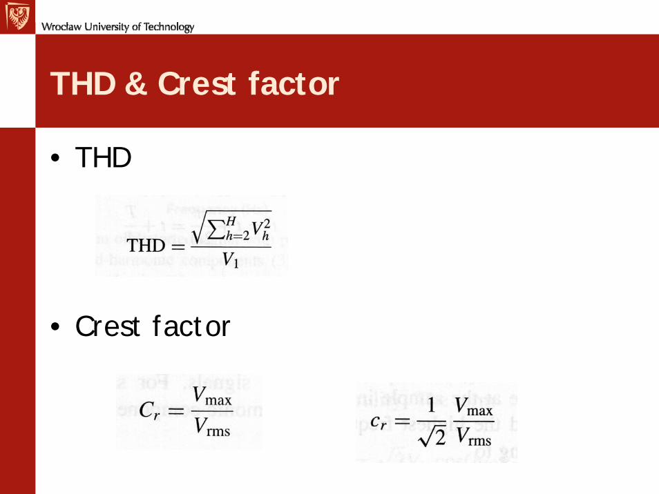
THD & Crest factor
• THD
• Crest factor
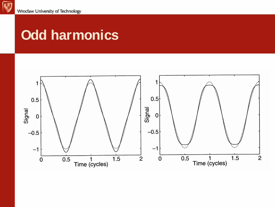
Odd harmonics
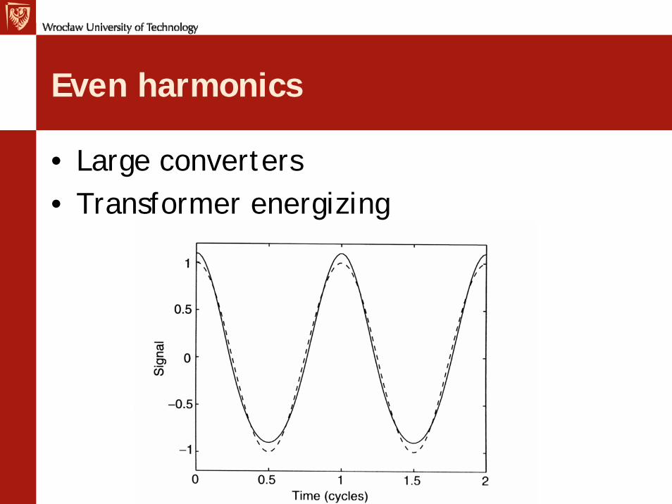
Even harmonics
• Large converters• Transformer energizing
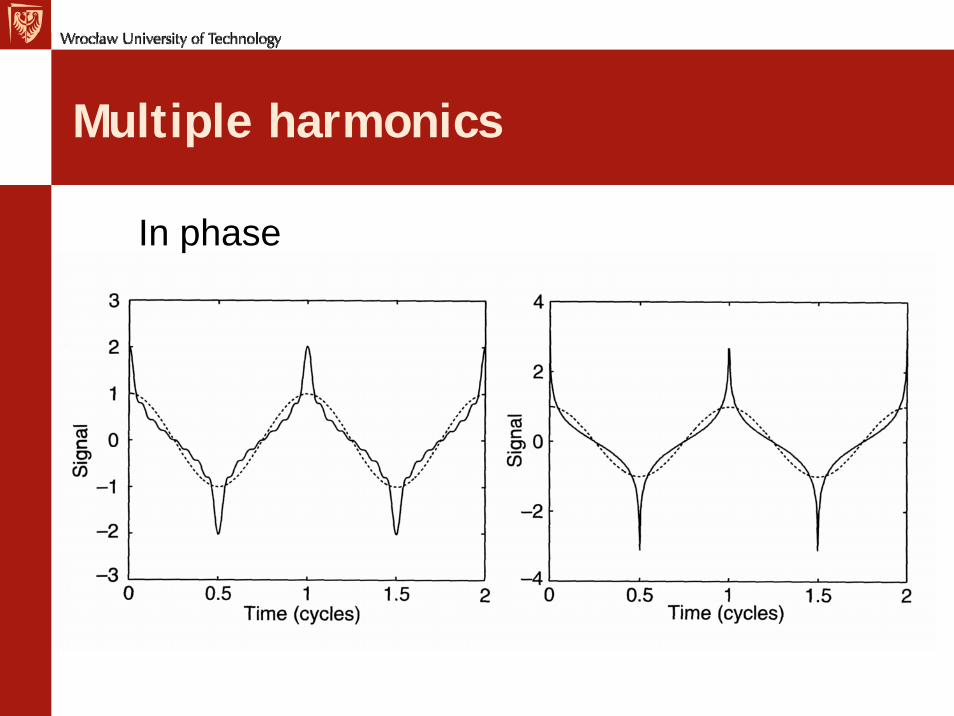
Multiple harmonics
In phase
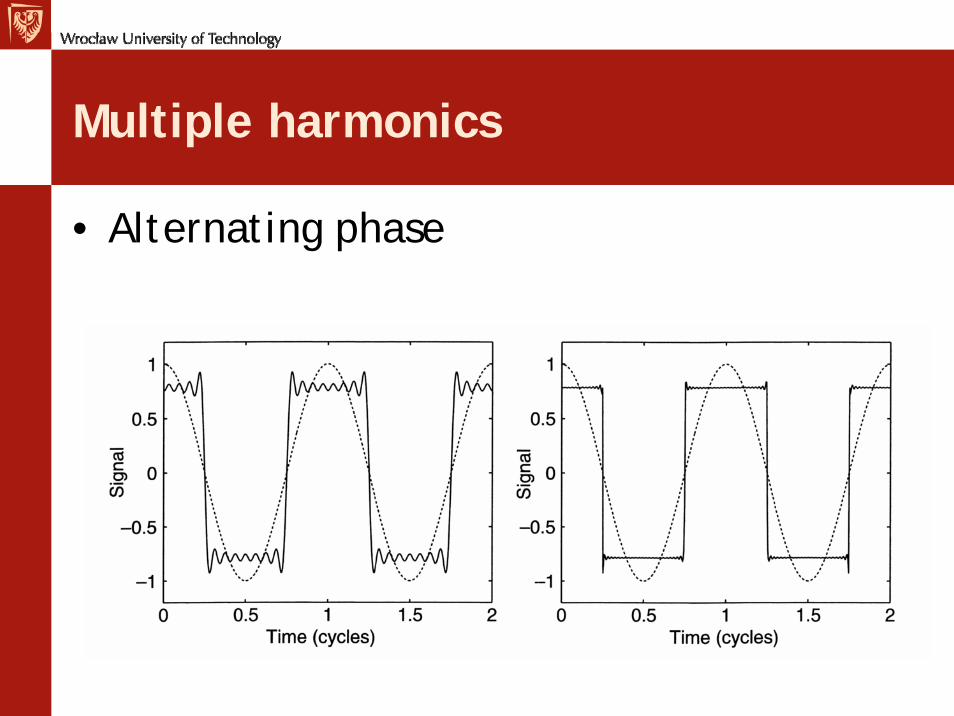
Multiple harmonics
• Alternating phase
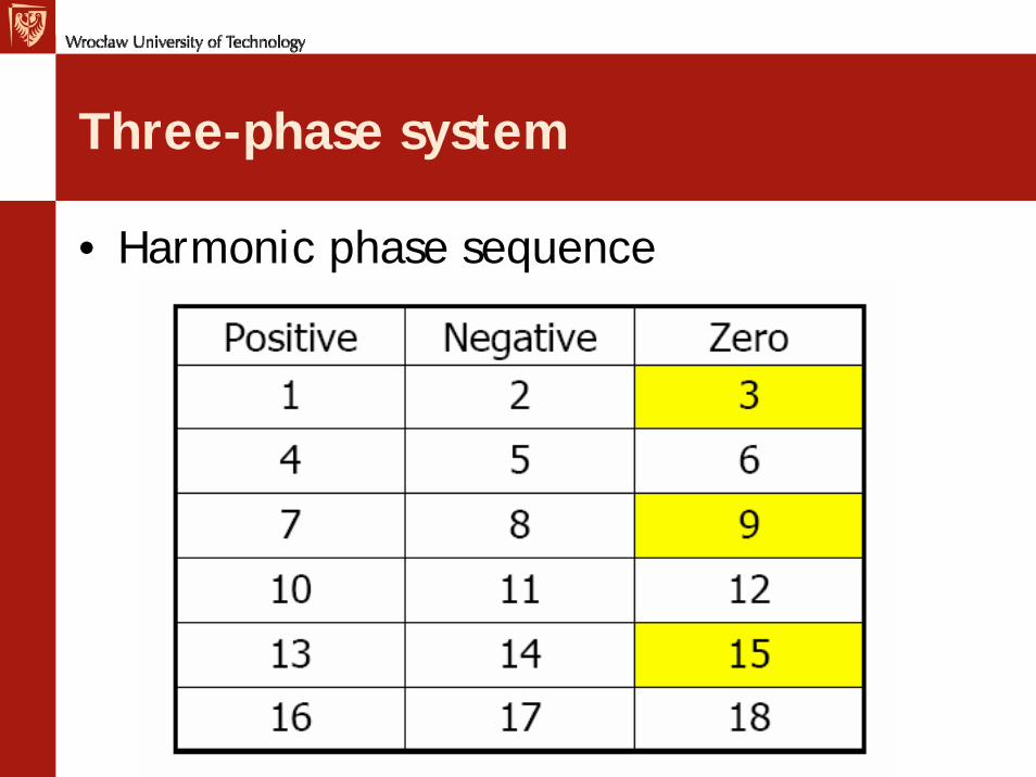
Three-phase system
• Harmonic phase sequence
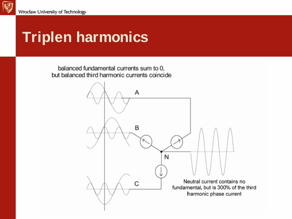
Triplen harmonics
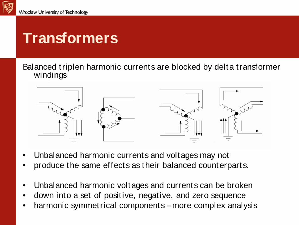
Transformers
Balanced triplen harmonic currents are blocked by delta transformer windings
• Unbalanced harmonic currents and voltages may not• produce the same effects as their balanced counterparts.
• Unbalanced harmonic voltages and currents can be broken• down into a set of positive, negative, and zero sequence• harmonic symmetrical components – more complex analysis
Sources of Waveform Distortion
Nonlinear Loads• Single-phase dc power supplies• Three-phase dc power supplies• Rectifiers• Transformers• Synchronous machines• Arc furnaces• Cycloconverters• …
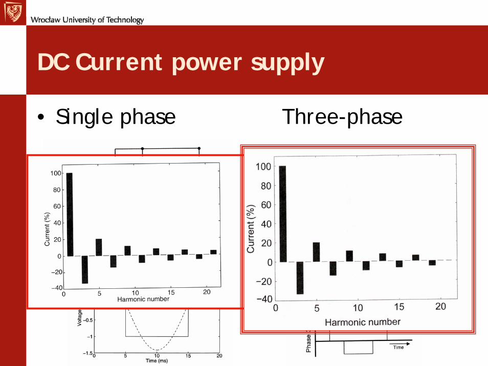
DC Current power supply
• Single phase Three-phase
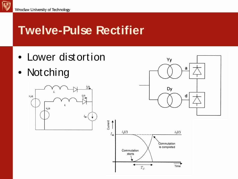
Twelve-Pulse Rectifier
• Lower distortion• Notching
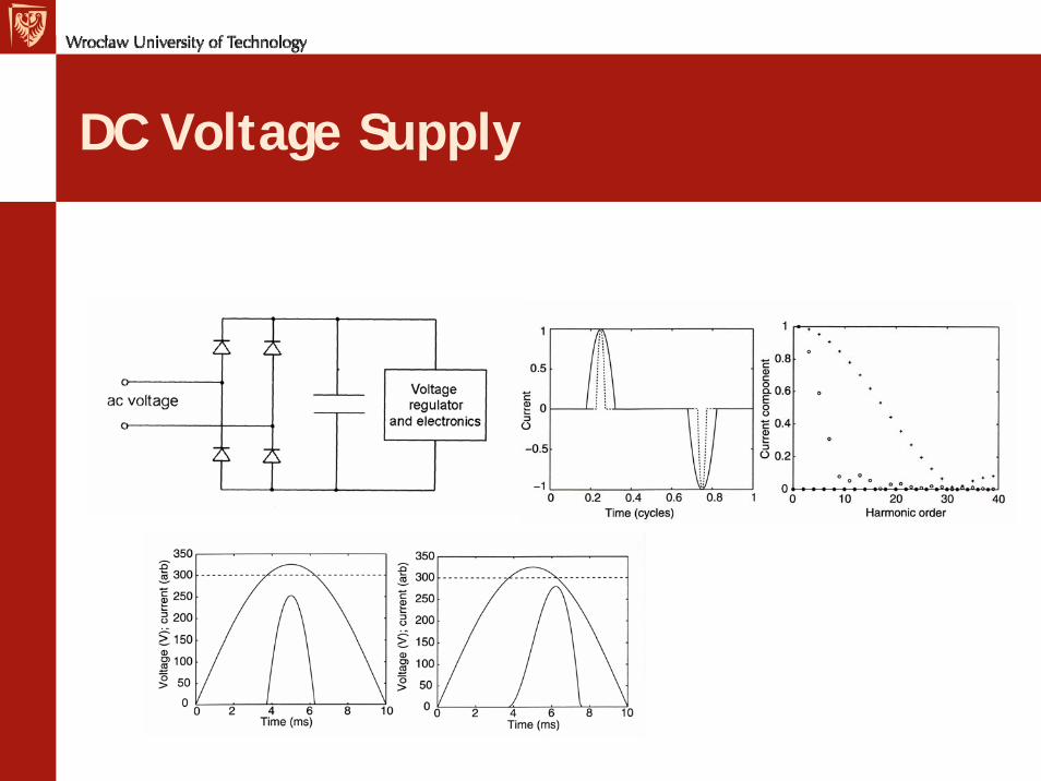
DC Voltage Supply
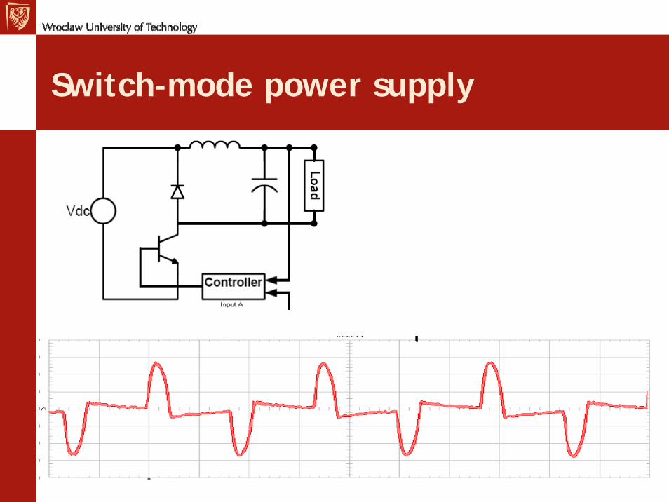
Switch-mode power supply
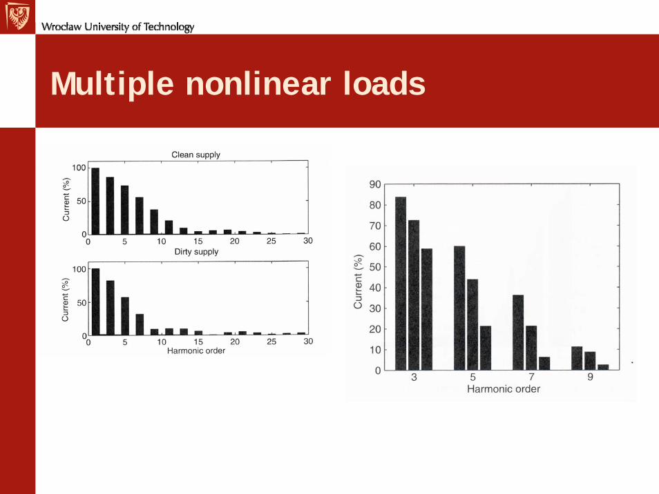
Multiple nonlinear loads
EN 50160
“Voltage Characteristics Of Electricity Supplied By Public Distribution Systems”
• –Voltage at the PCC only• – Addresses harmonics, sags, swells, etc.• – Incorporated in newer power quality
recorders• – Describes 95% conditions• – Operation at minimum requirements is
not likely to be acceptable to customers.
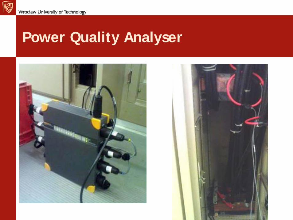
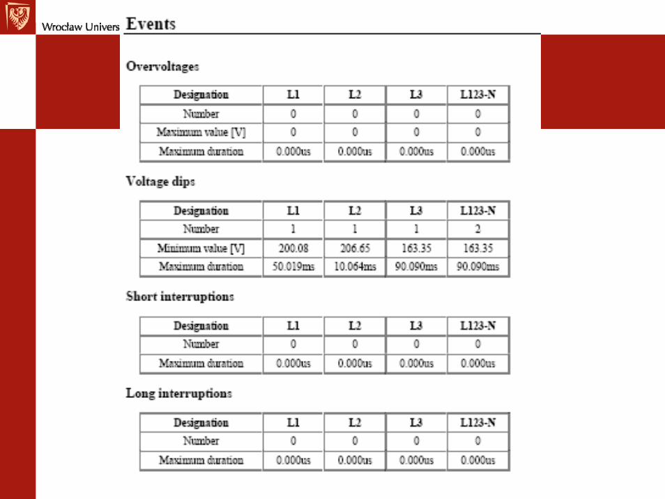
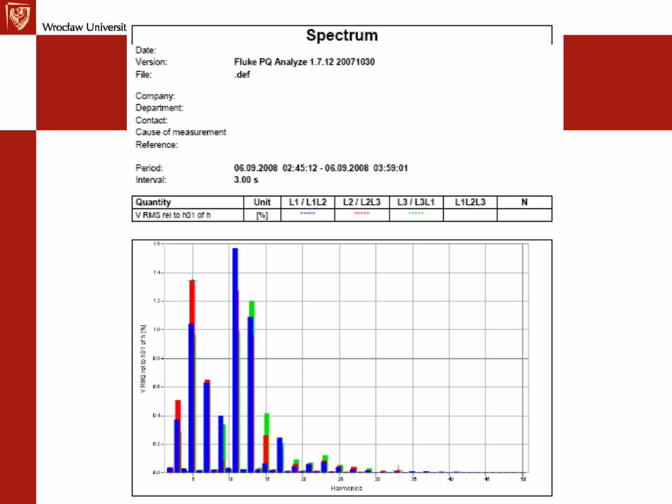
Power Quality Analyser
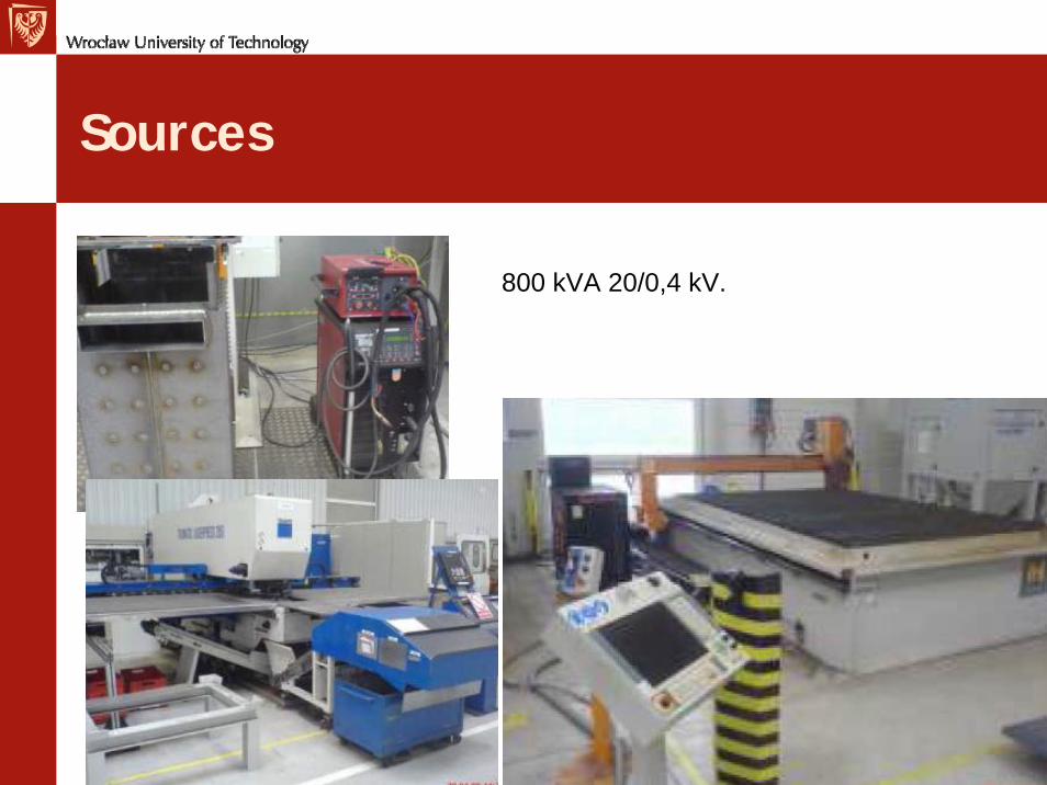
Sources
800 kVA 20/0,4 kV.
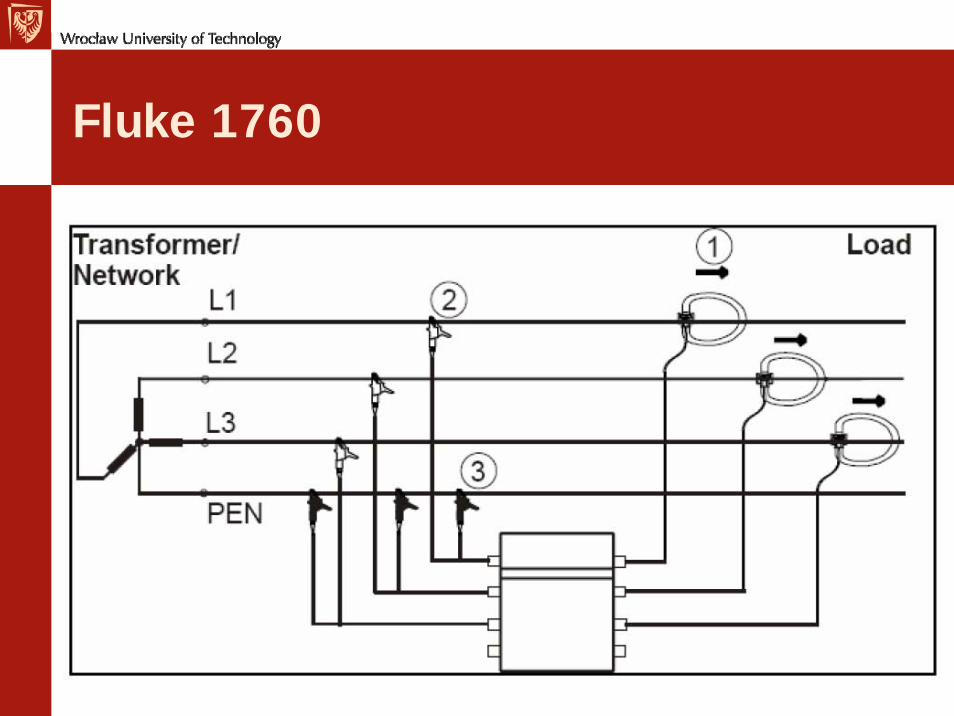
Fluke 1760
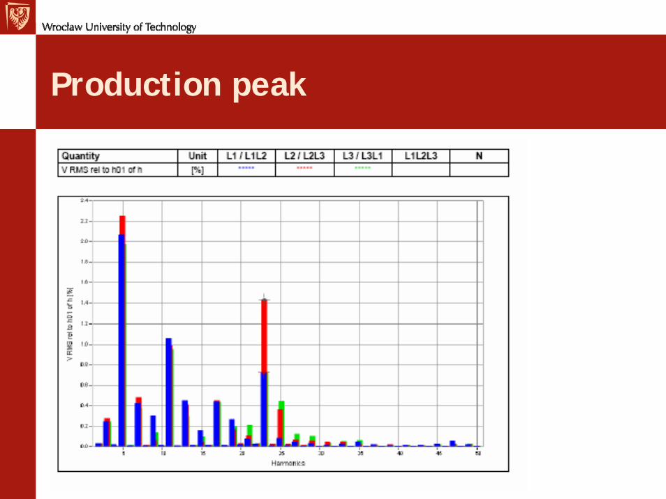
Production peak
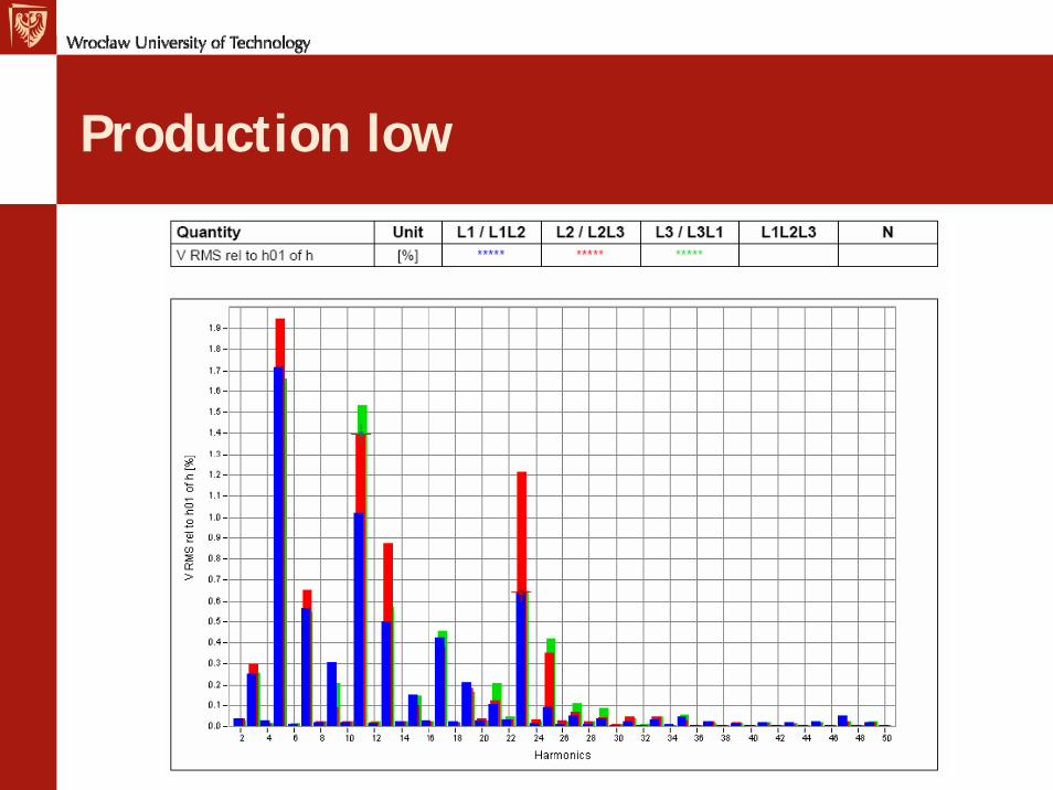
Production low
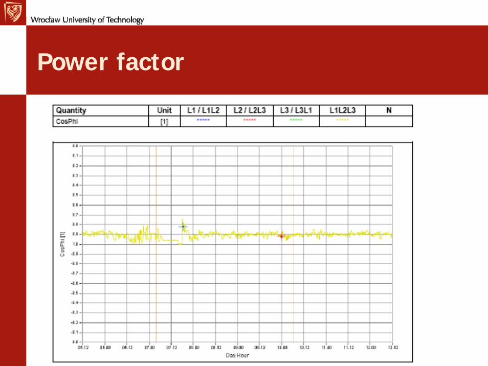
Power factor
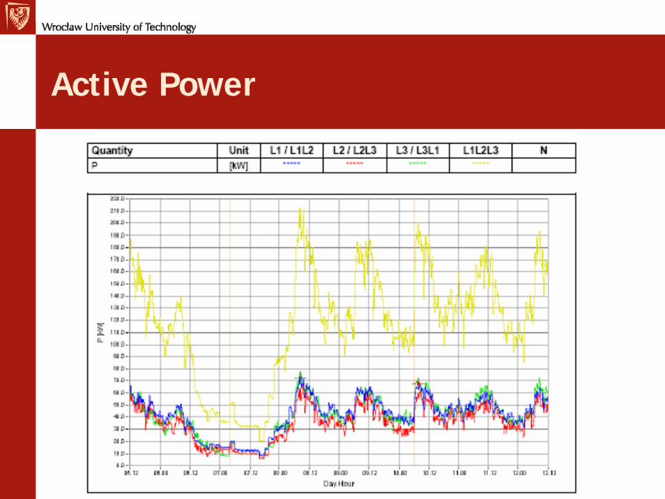
Active Power
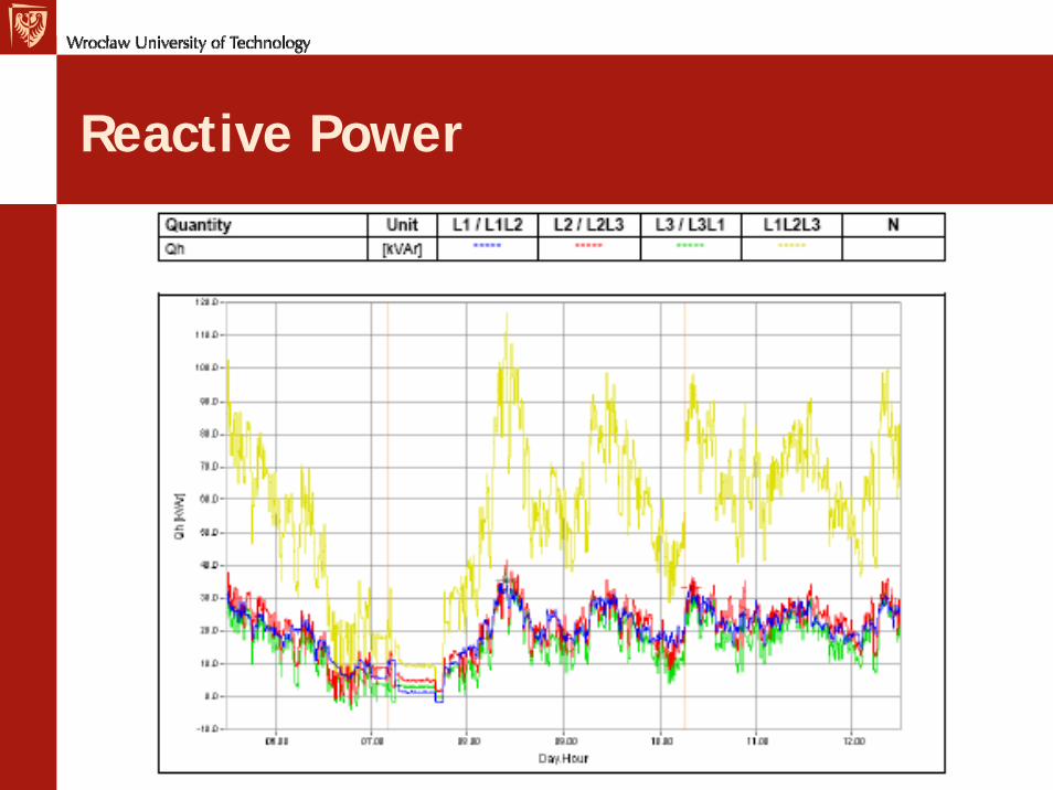
Reactive Power
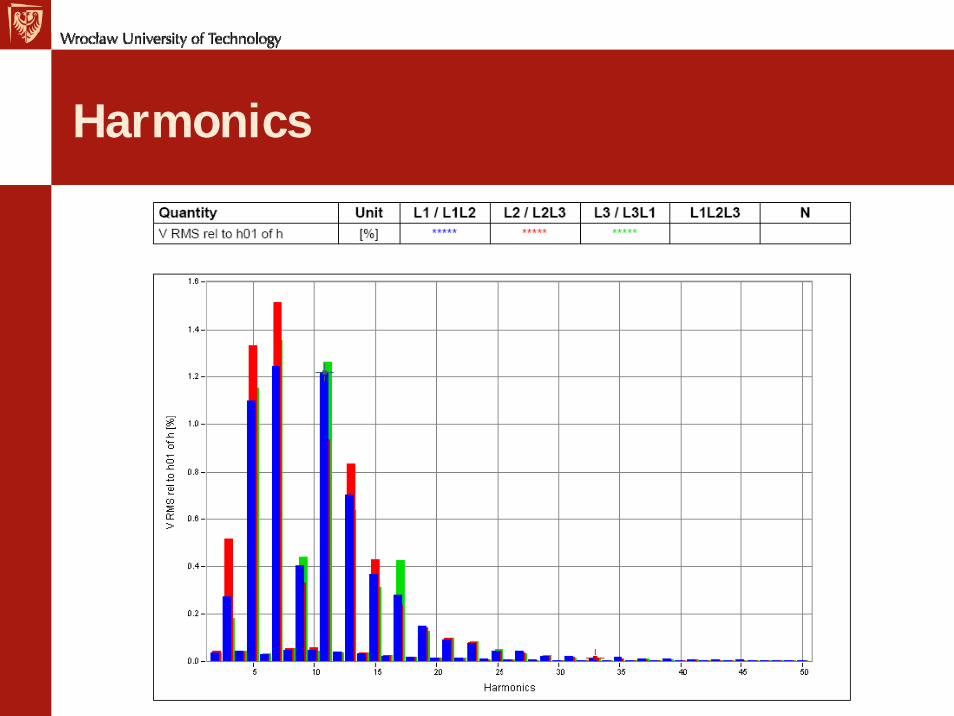
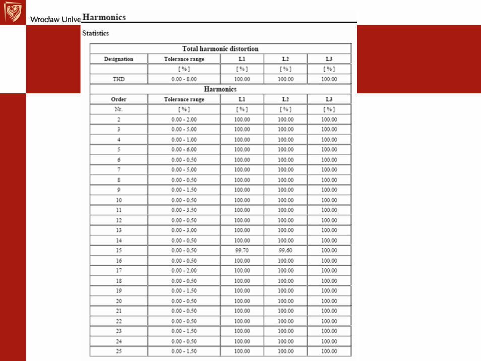
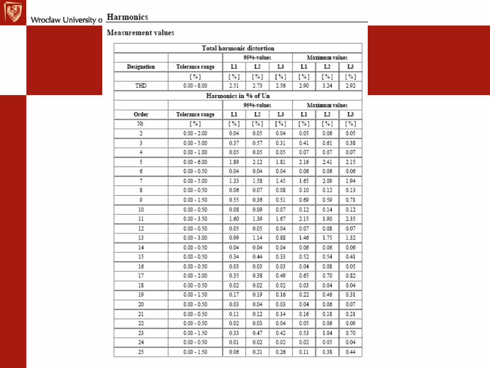
Harmonics
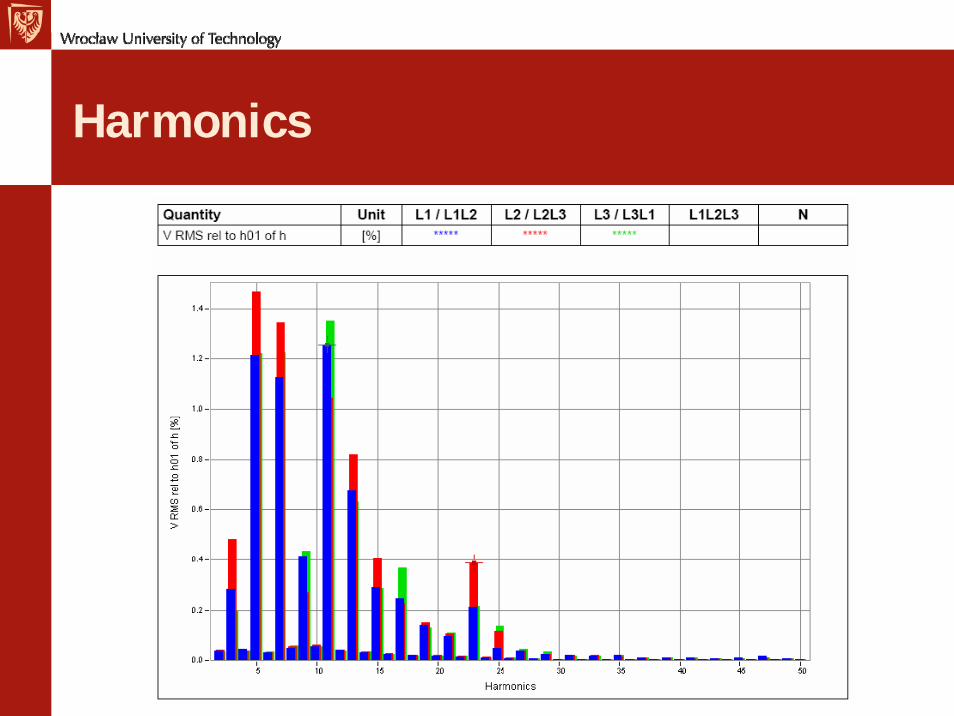
Harmonics
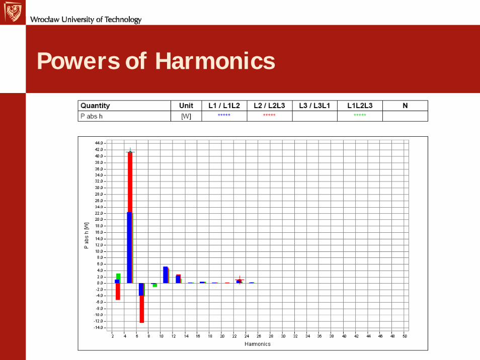
Powers of Harmonics
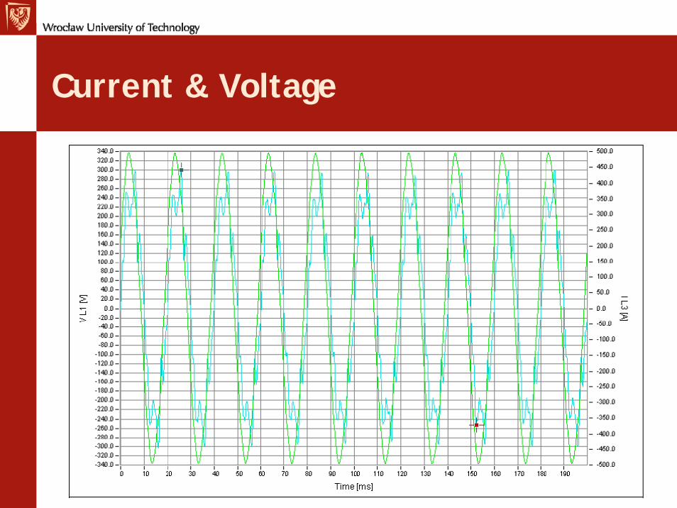
Current & Voltage