NMR and MRI - Prizztech Oy · PDF fileis used to get μV level signals. ... School of...
98
Seppo Vahasalo Philips Medical Systems MR Finland 2008-06-17 NMR and MRI
Transcript of NMR and MRI - Prizztech Oy · PDF fileis used to get μV level signals. ... School of...
Seppo VahasaloPhilips Medical Systems MR Finland2008-06-17
NMR and MRI
2Philips Medical Systems MR Finland, Seppo Vahasalo, 2008-06-17
Contents
• Some local MRI history
• NMR and MRI Physics
• Magnet technology and electronics
• Recent trends in MRI and magnet technology
• Markets and players
• Magnetic fields. Safety, EMF directive
3Philips Medical Systems MR Finland, Seppo Vahasalo, 2008-06-17
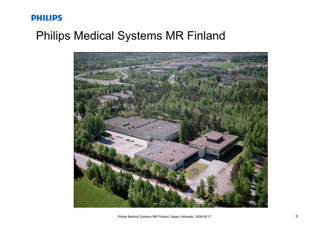
Philips Medical Systems MR Finland
4Philips Medical Systems MR Finland, Seppo Vahasalo, 2008-06-17
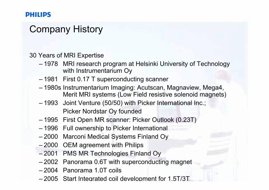
Company History
30 Years of MRI Expertise– 1978 MRI research program at Helsinki University of Technology
with Instrumentarium Oy– 1981 First 0.17 T superconducting scanner– 1980s Instrumentarium Imaging: Acutscan, Magnaview, Mega4,
Merit MRI systems (Low Field resistive solenoid magnets) – 1993 Joint Venture (50/50) with Picker International Inc.;
Picker Nordstar Oy founded – 1995 First Open MR scanner: Picker Outlook (0.23T)– 1996 Full ownership to Picker International– 2000 Marconi Medical Systems Finland Oy– 2000 OEM agreement with Philips– 2001 PMS MR Technologies Finland Oy– 2002 Panorama 0.6T with superconducting magnet– 2004 Panorama 1.0T coils– 2005 Start Integrated coil development for 1.5T/3T
5Philips Medical Systems MR Finland, Seppo Vahasalo, 2008-06-17
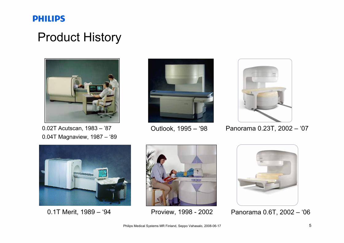
Product History
Outlook, 1995 – ‘98
Proview, 1998 - 2002
0.02T Acutscan, 1983 – ’870.04T Magnaview, 1987 – ‘89
0.1T Merit, 1989 – ‘94
Panorama 0.23T, 2002 – ‘07
Panorama 0.6T, 2002 – ‘06
6Philips Medical Systems MR Finland, Seppo Vahasalo, 2008-06-17
NMR and MRI
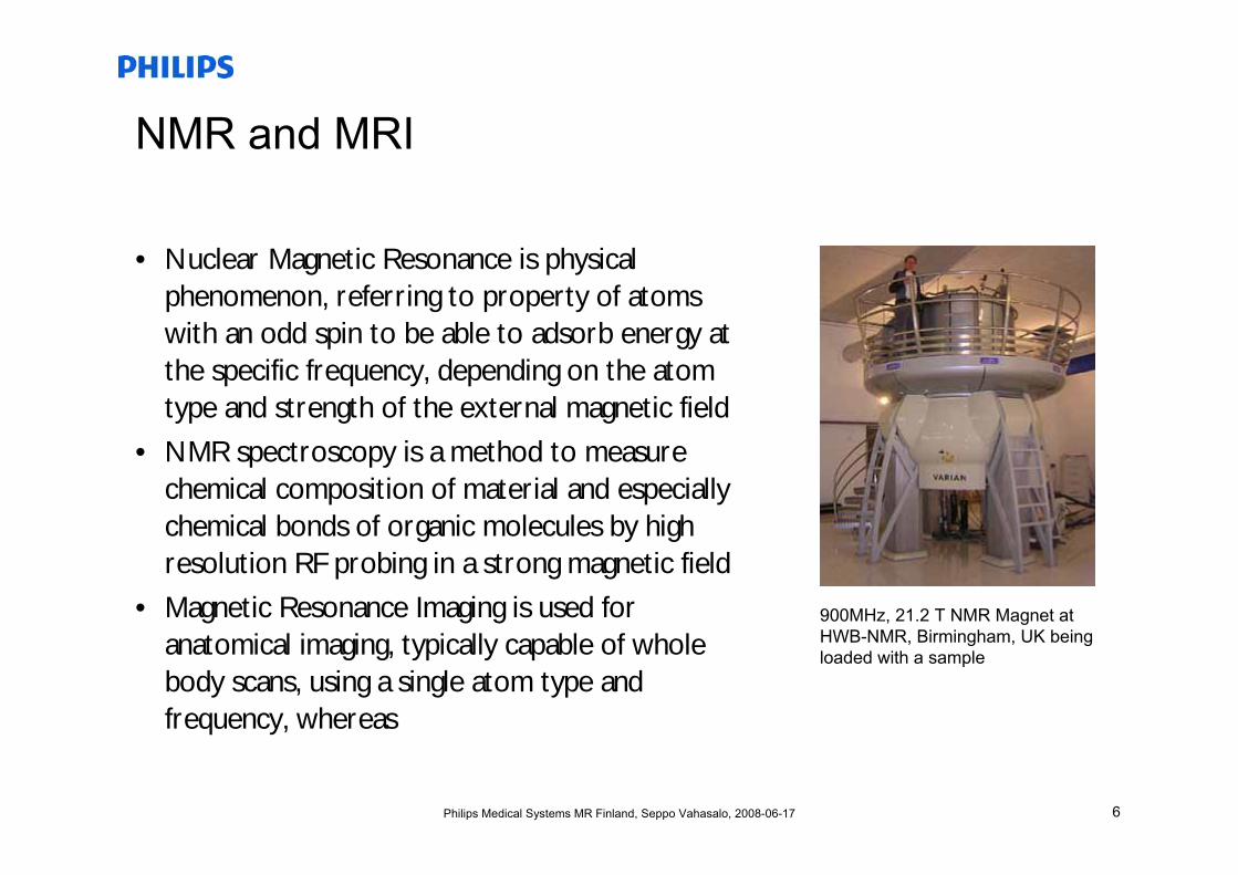
• Nuclear Magnetic Resonance is physical phenomenon, referring to property of atoms with an odd spin to be able to adsorb energy at the specific frequency, depending on the atom type and strength of the external magnetic field
• NMR spectroscopy is a method to measure chemical composition of material and especially chemical bonds of organic molecules by high resolution RF probing in a strong magnetic field
• Magnetic Resonance Imaging is used for anatomical imaging, typically capable of whole body scans, using a single atom type and frequency, whereas
900MHz, 21.2 T NMR Magnet at HWB-NMR, Birmingham, UK being loaded with a sample
7Philips Medical Systems MR Finland, Seppo Vahasalo, 2008-06-17
Physics of NMR - Polarization
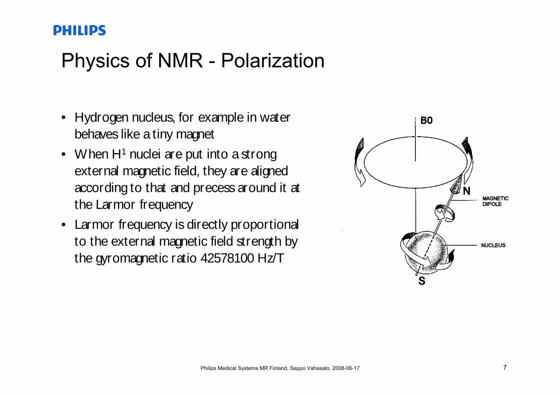
• Hydrogen nucleus, for example in water behaves like a tiny magnet
• When H1 nuclei are put into a strong external magnetic field, they are aligned according to that and precess around it at the Larmor frequency
• Larmor frequency is directly proportional to the external magnetic field strength by the gyromagnetic ratio 42578100 Hz/T
8Philips Medical Systems MR Finland, Seppo Vahasalo, 2008-06-17
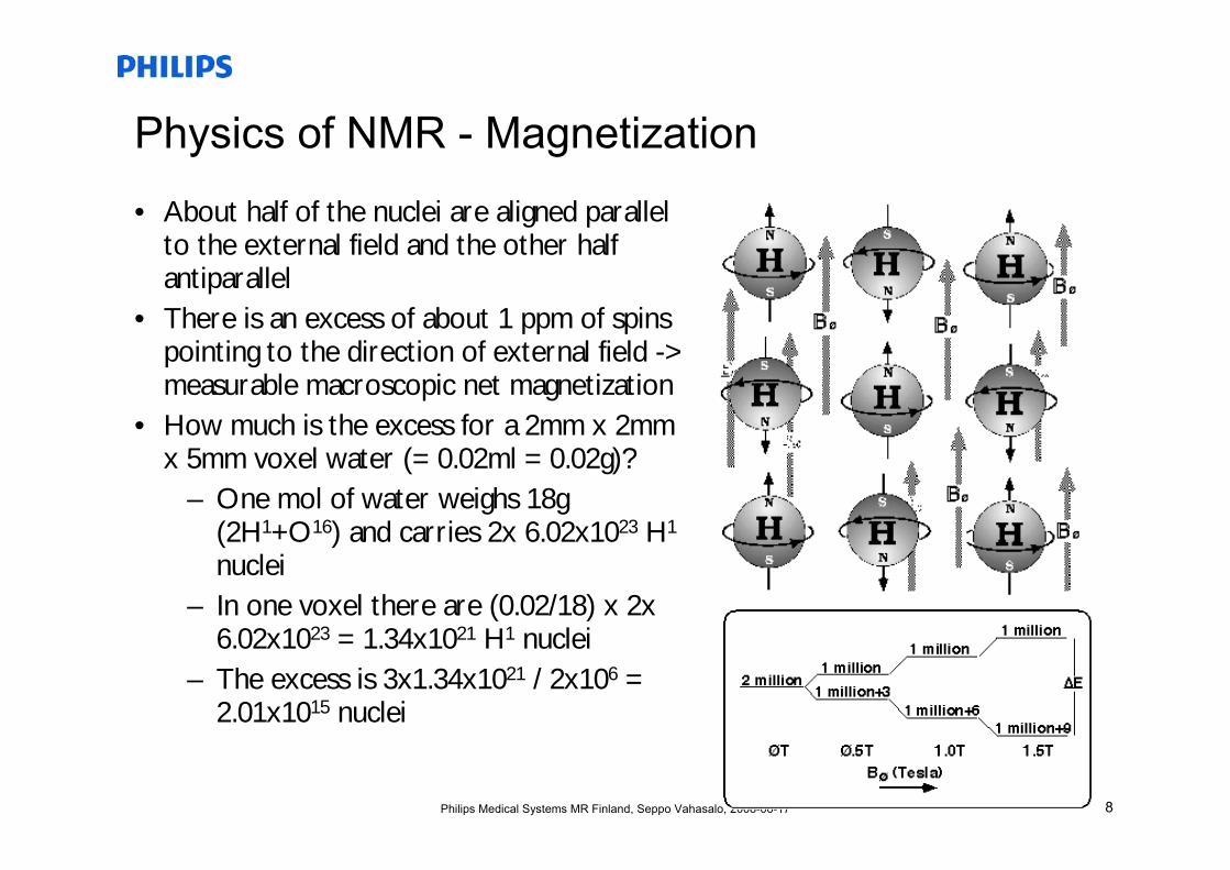
Physics of NMR - Magnetization
• About half of the nuclei are aligned parallel to the external field and the other half antiparallel
• There is an excess of about 1 ppm of spins pointing to the direction of external field -> measurable macroscopic net magnetization
• How much is the excess for a 2mm x 2mm x 5mm voxel water (= 0.02ml = 0.02g)?
– One mol of water weighs 18g (2H1+O16) and carries 2x 6.02x1023 H1
nuclei– In one voxel there are (0.02/18) x 2x
6.02x1023 = 1.34x10²¹ H1 nuclei– The excess is 3x1.34x1021 / 2x106 =
2.01x10¹⁵ nuclei
9Philips Medical Systems MR Finland, Seppo Vahasalo, 2008-06-17
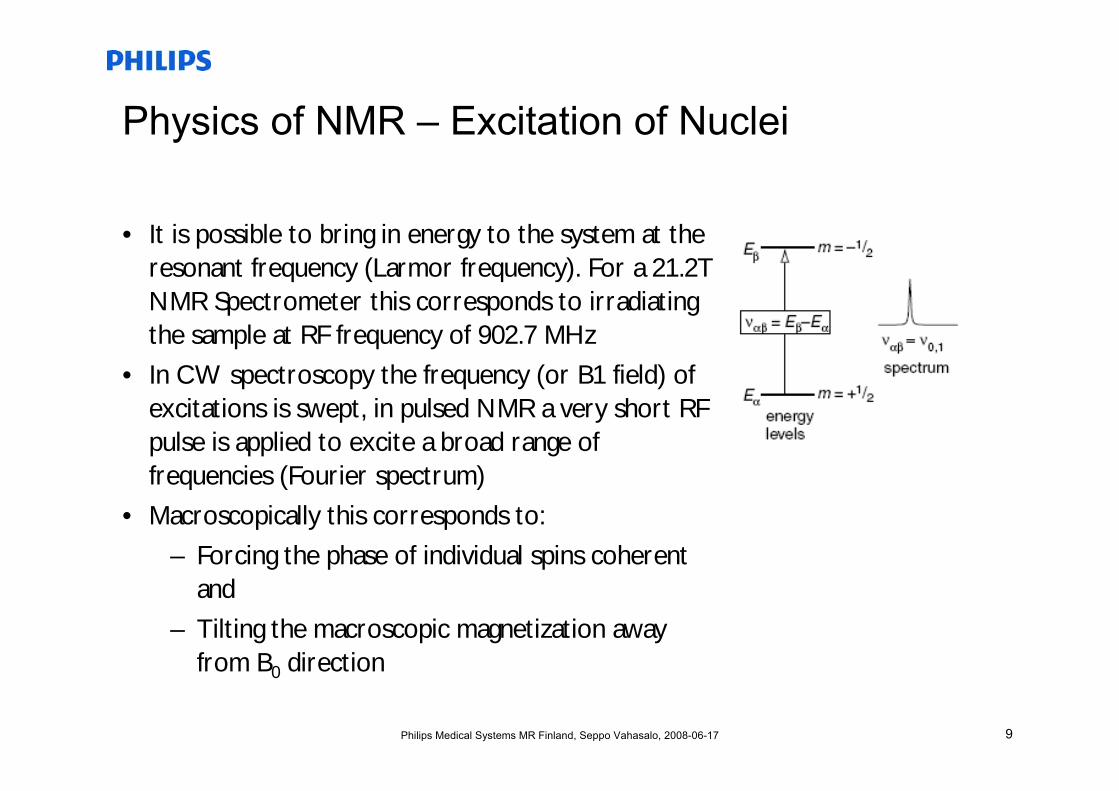
Physics of NMR – Excitation of Nuclei
• It is possible to bring in energy to the system at the resonant frequency (Larmor frequency). For a 21.2T NMR Spectrometer this corresponds to irradiating the sample at RF frequency of 902.7 MHz
• In CW spectroscopy the frequency (or B1 field) of excitations is swept, in pulsed NMR a very short RF pulse is applied to excite a broad range of frequencies (Fourier spectrum)
• Macroscopically this corresponds to:
– Forcing the phase of individual spins coherent and
– Tilting the macroscopic magnetization away from B0 direction
10Philips Medical Systems MR Finland, Seppo Vahasalo, 2008-06-17
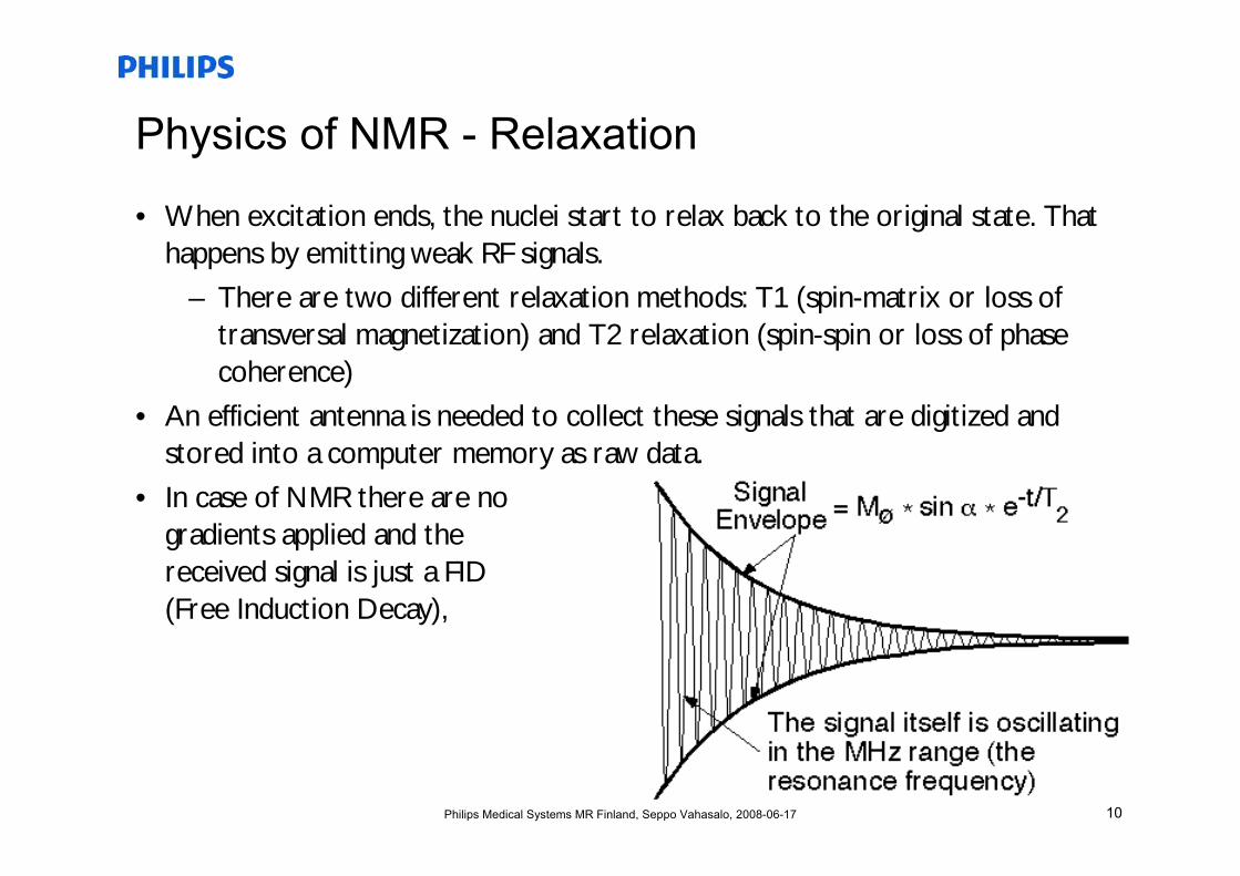
Physics of NMR - Relaxation
• When excitation ends, the nuclei start to relax back to the original state. That happens by emitting weak RF signals.
– There are two different relaxation methods: T1 (spin-matrix or loss of transversal magnetization) and T2 relaxation (spin-spin or loss of phase coherence)
• An efficient antenna is needed to collect these signals that are digitized and stored into a computer memory as raw data.
• In case of NMR there are no gradients applied and the received signal is just a FID(Free Induction Decay),
11Philips Medical Systems MR Finland, Seppo Vahasalo, 2008-06-17
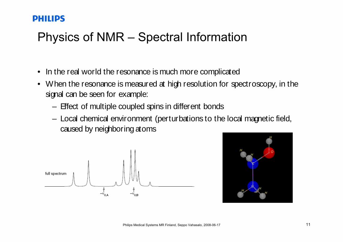
Physics of NMR – Spectral Information
• In the real world the resonance is much more complicated
• When the resonance is measured at high resolution for spectroscopy, in the signal can be seen for example:
– Effect of multiple coupled spins in different bonds
– Local chemical environment (perturbations to the local magnetic field, caused by neighboring atoms
12Philips Medical Systems MR Finland, Seppo Vahasalo, 2008-06-17
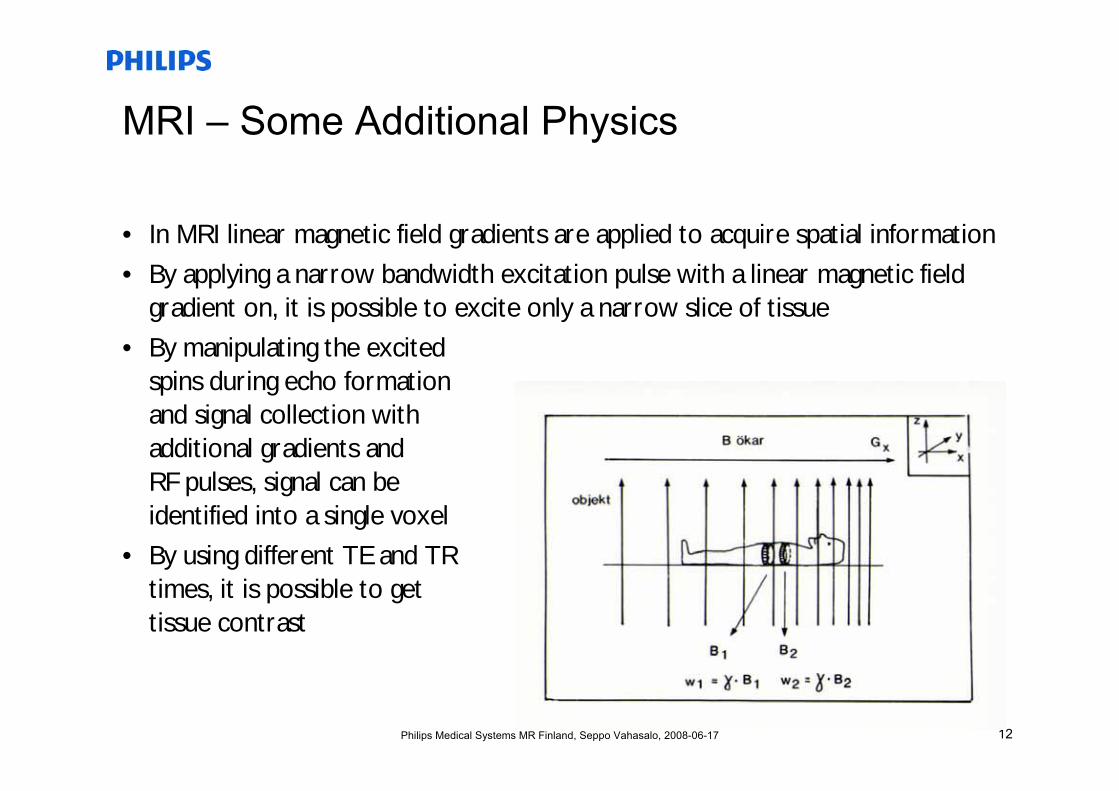
MRI – Some Additional Physics
• In MRI linear magnetic field gradients are applied to acquire spatial information
• By applying a narrow bandwidth excitation pulse with a linear magnetic field gradient on, it is possible to excite only a narrow slice of tissue
• By manipulating the excitedspins during echo formationand signal collection withadditional gradients and RF pulses, signal can beidentified into a single voxel
• By using different TE and TRtimes, it is possible to gettissue contrast
13Philips Medical Systems MR Finland, Seppo Vahasalo, 2008-06-17
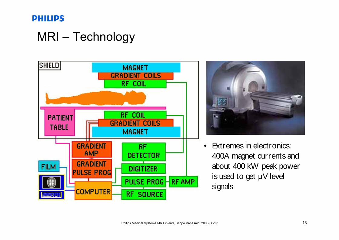
MRI – Technology
• Extremes in electronics: 400A magnet currents and about 400 kW peak power is used to get μV level signals
14Philips Medical Systems MR Finland, Seppo Vahasalo, 2008-06-17
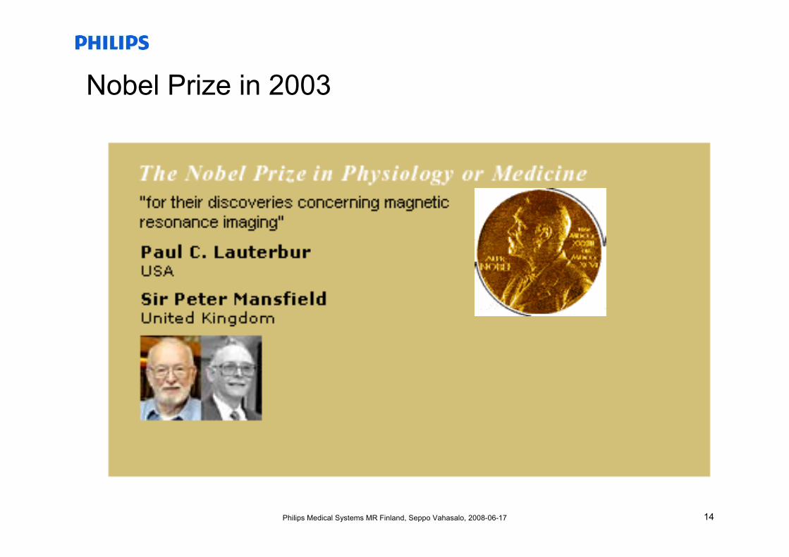
Nobel Prize in 2003
15Philips Medical Systems MR Finland, Seppo Vahasalo, 2008-06-17
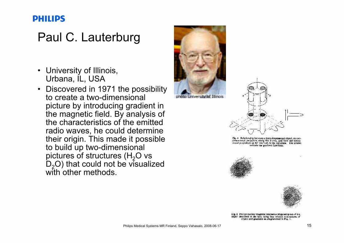
Paul C. Lauterburg
• University of Illinois, Urbana, IL, USA
• Discovered in 1971 the possibility to create a two-dimensional picture by introducing gradient in the magnetic field. By analysis of the characteristics of the emitted radio waves, he could determine their origin. This made it possible to build up two-dimensional pictures of structures (H2O vsD2O) that could not be visualized with other methods.
16Philips Medical Systems MR Finland, Seppo Vahasalo, 2008-06-17
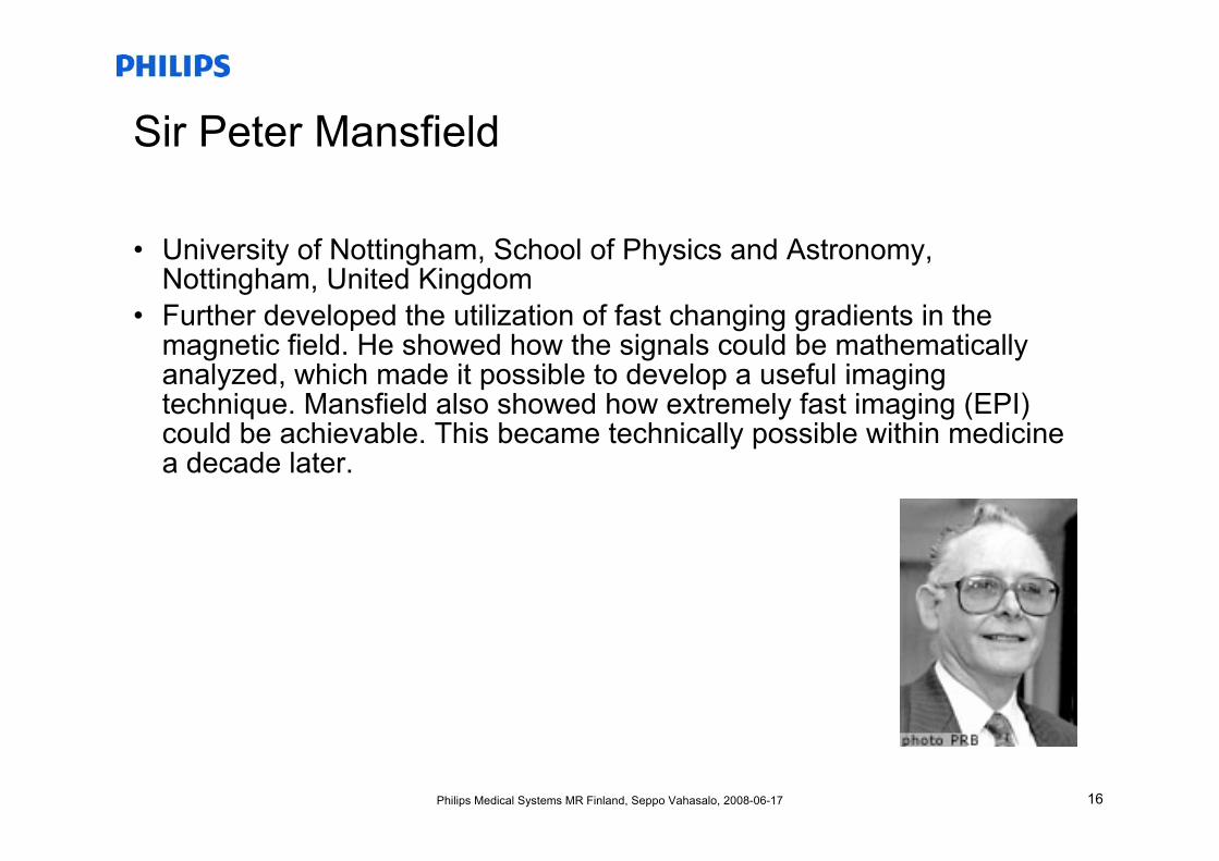
Sir Peter Mansfield
• University of Nottingham, School of Physics and Astronomy, Nottingham, United Kingdom
• Further developed the utilization of fast changing gradients in the magnetic field. He showed how the signals could be mathematically analyzed, which made it possible to develop a useful imaging technique. Mansfield also showed how extremely fast imaging (EPI) could be achievable. This became technically possible within medicine a decade later.
17Philips Medical Systems MR Finland, Seppo Vahasalo, 2008-06-17
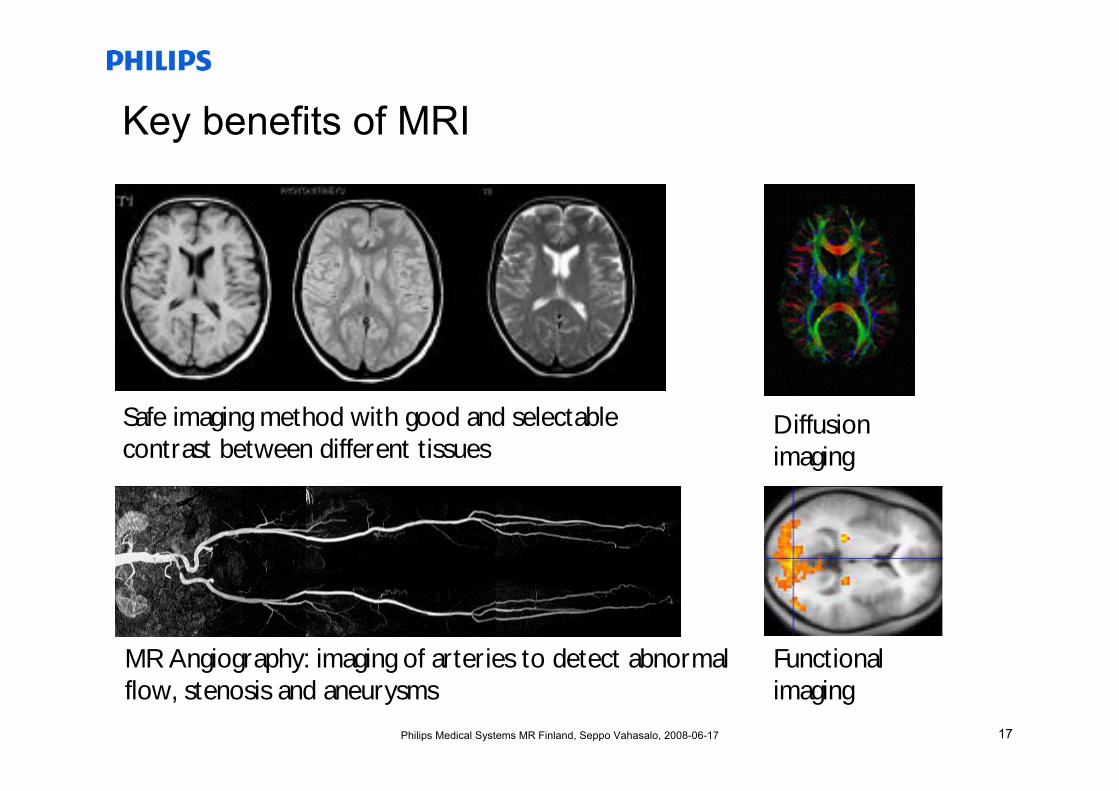
Key benefits of MRI
Safe imaging method with good and selectablecontrast between different tissues
Diffusion imaging
MR Angiography: imaging of arteries to detect abnormalflow, stenosis and aneurysms
Functional imaging
18Philips Medical Systems MR Finland, Seppo Vahasalo, 2008-06-17
MRI Magnets
19Philips Medical Systems MR Finland, Seppo Vahasalo, 2008-06-17
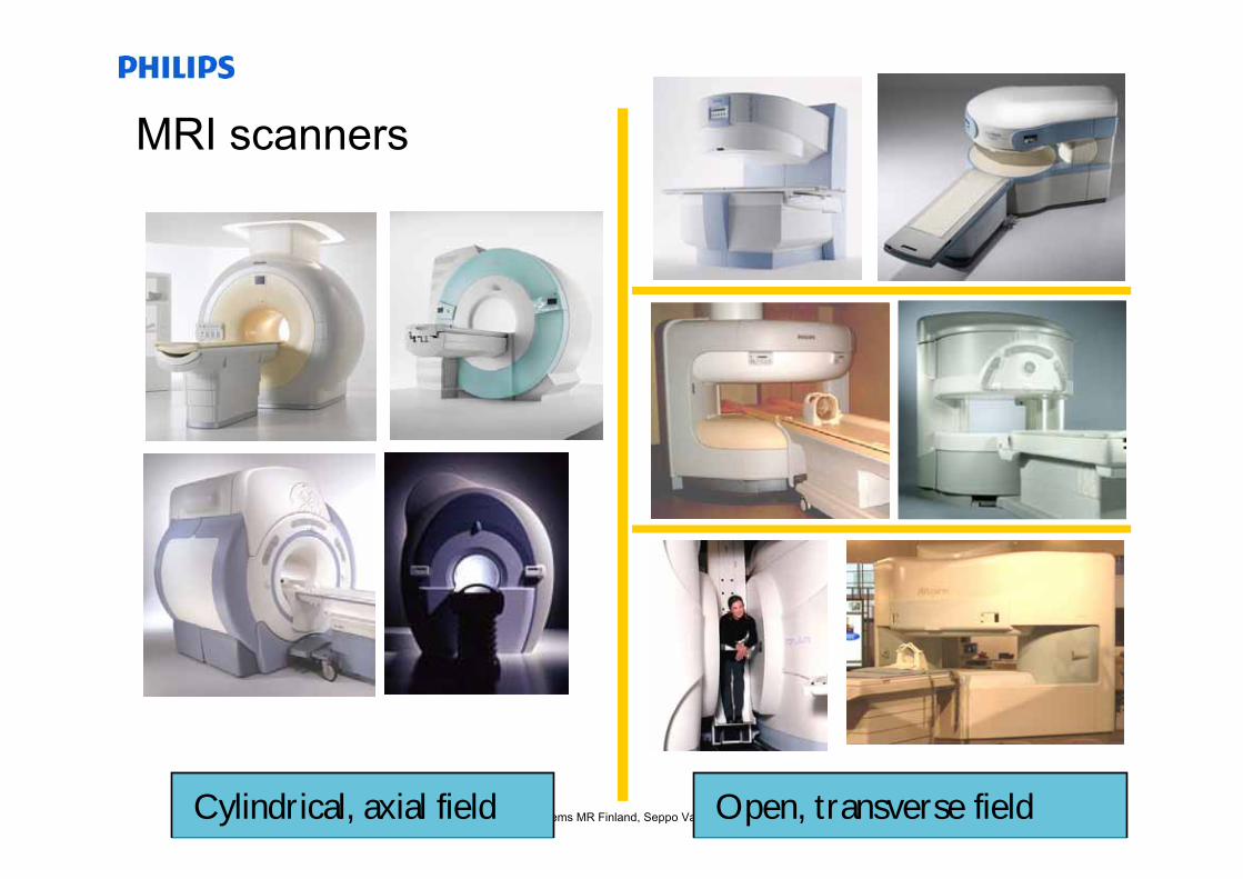
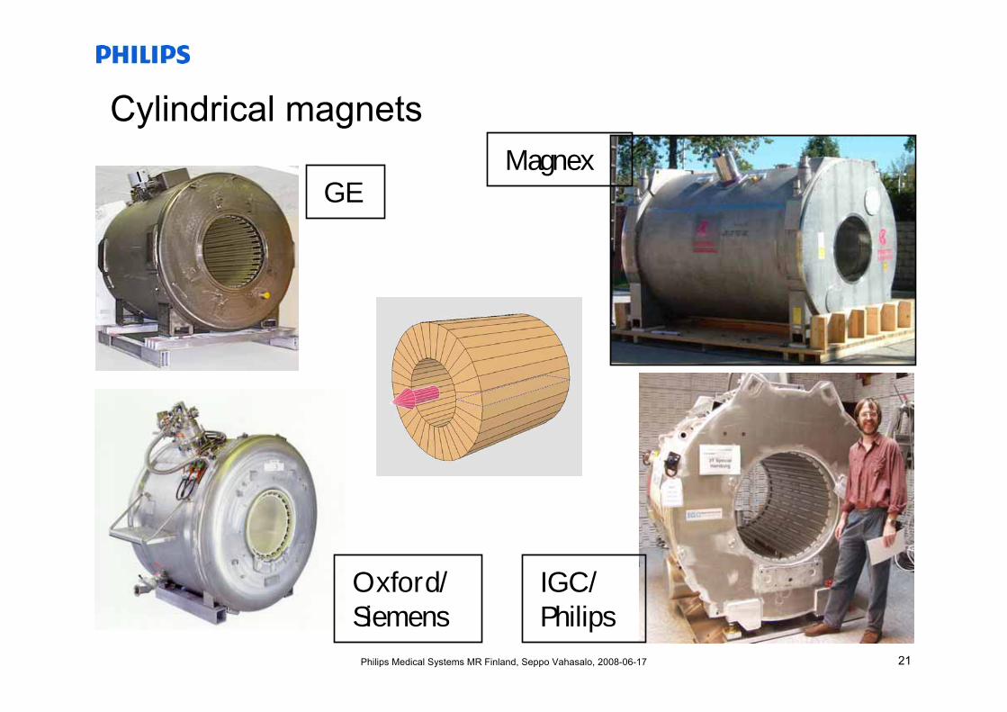
MRI scanners
Cylindrical, axial field Open, transverse field
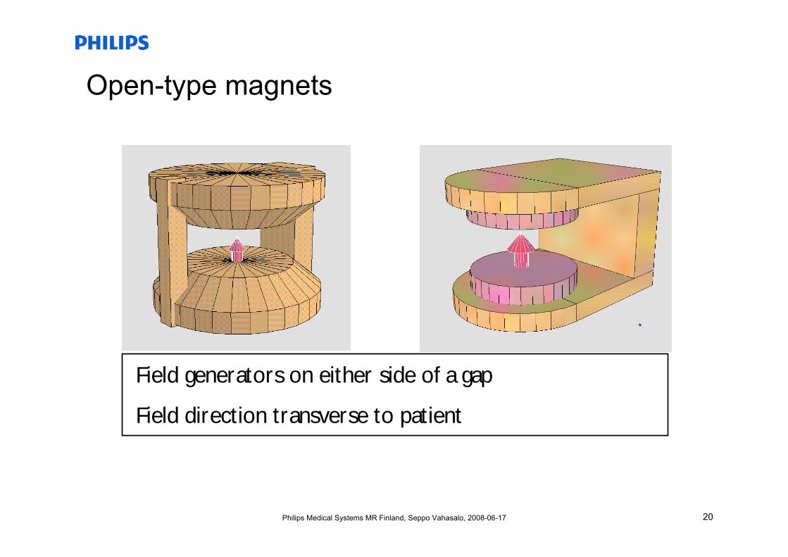
20Philips Medical Systems MR Finland, Seppo Vahasalo, 2008-06-17
Open-type magnets
Field generators on either side of a gap
Field direction transverse to patient
21Philips Medical Systems MR Finland, Seppo Vahasalo, 2008-06-17
Cylindrical magnets
GE
Oxford/ Siemens
IGC/ Philips
Magnex
22Philips Medical Systems MR Finland, Seppo Vahasalo, 2008-06-17
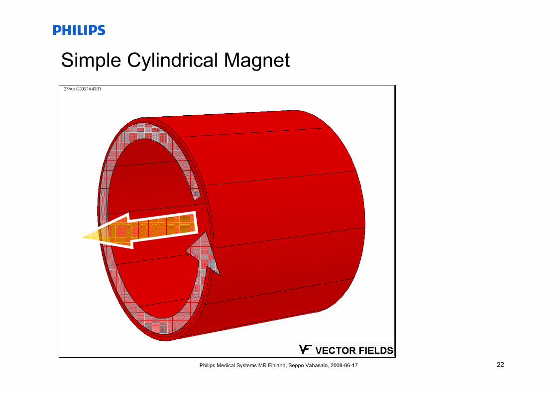
Simple Cylindrical Magnet
23Philips Medical Systems MR Finland, Seppo Vahasalo, 2008-06-17
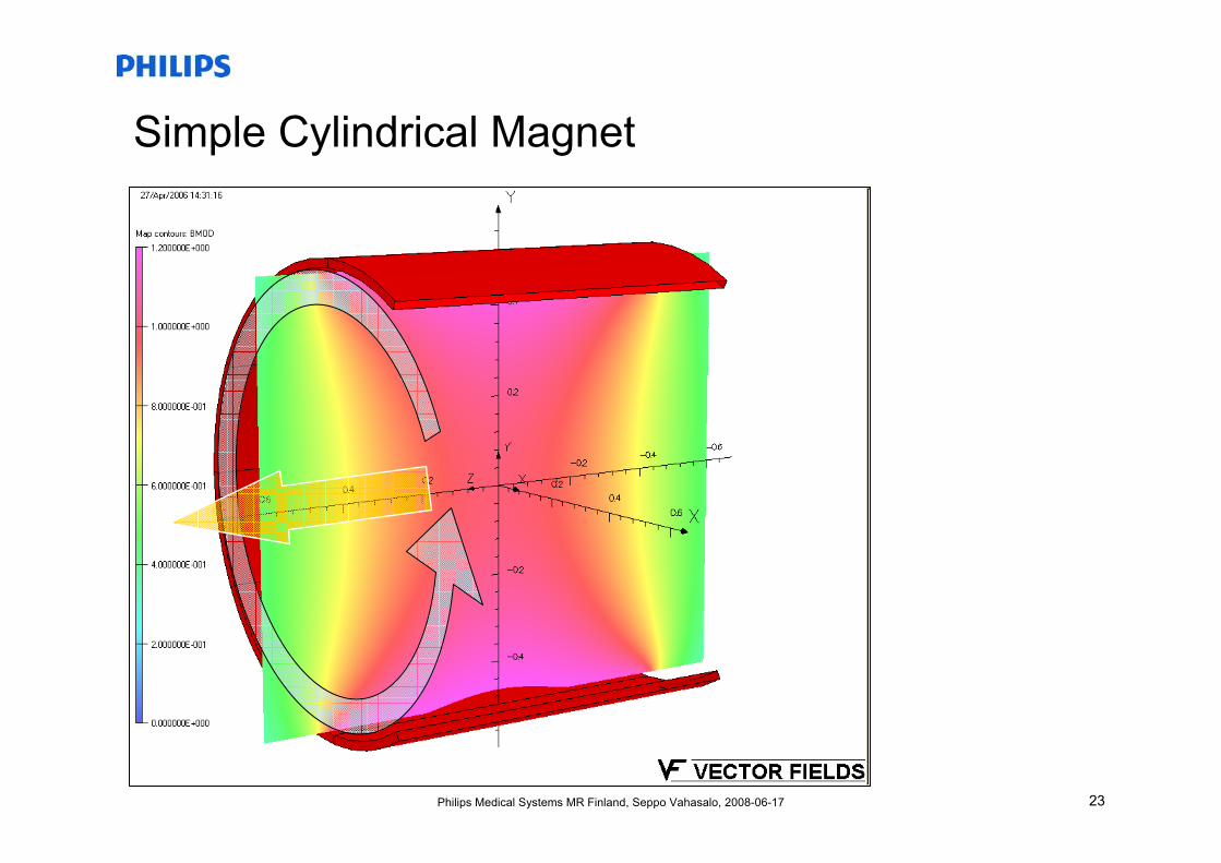
Simple Cylindrical Magnet
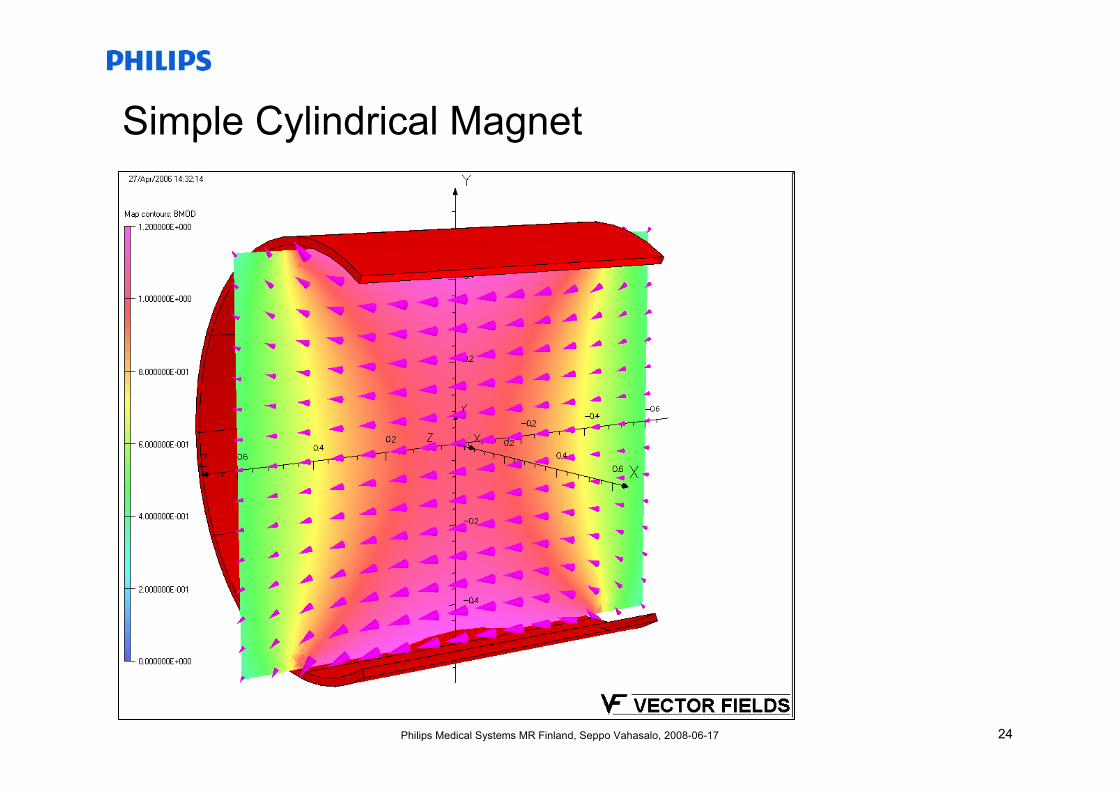
24Philips Medical Systems MR Finland, Seppo Vahasalo, 2008-06-17
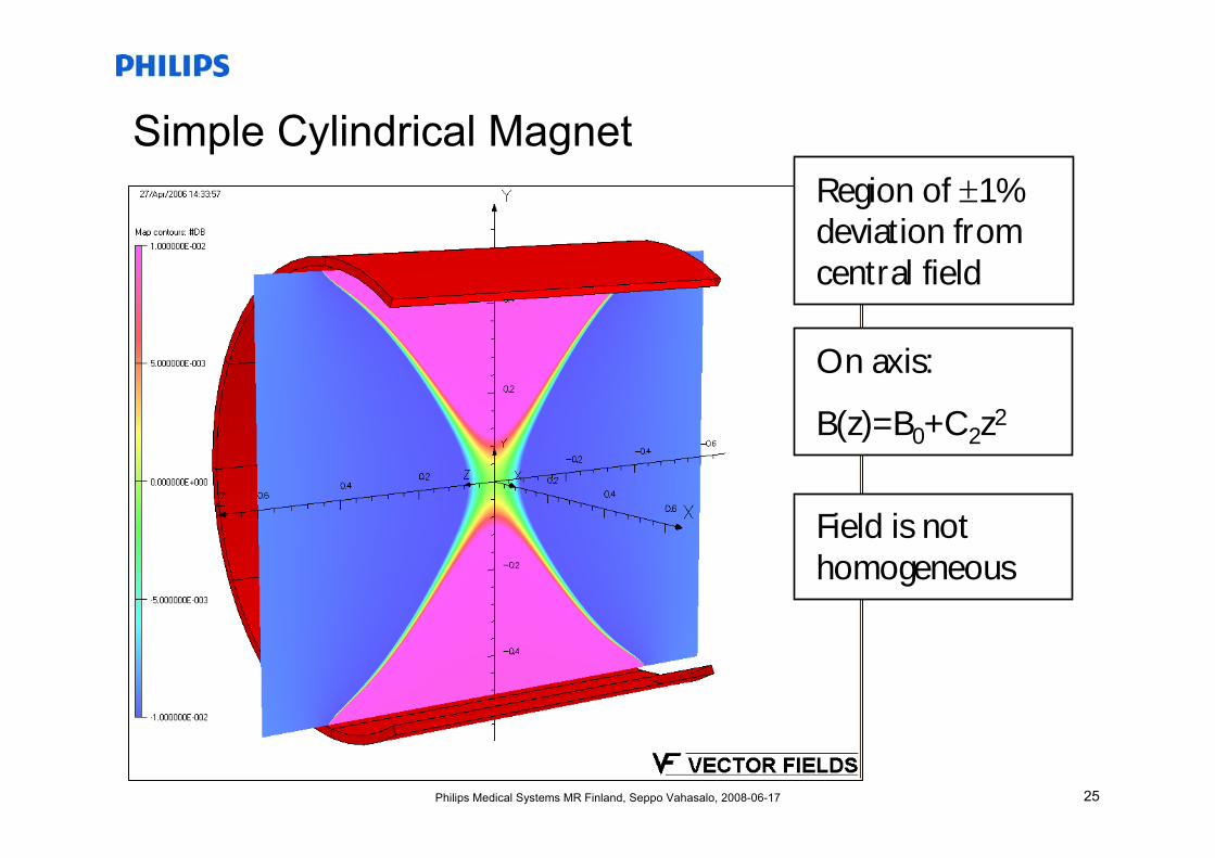
Simple Cylindrical Magnet
25Philips Medical Systems MR Finland, Seppo Vahasalo, 2008-06-17
Simple Cylindrical MagnetRegion of ±1% deviation from central field
On axis:
B(z)=B0+C2z2
Field is not homogeneous
26Philips Medical Systems MR Finland, Seppo Vahasalo, 2008-06-17
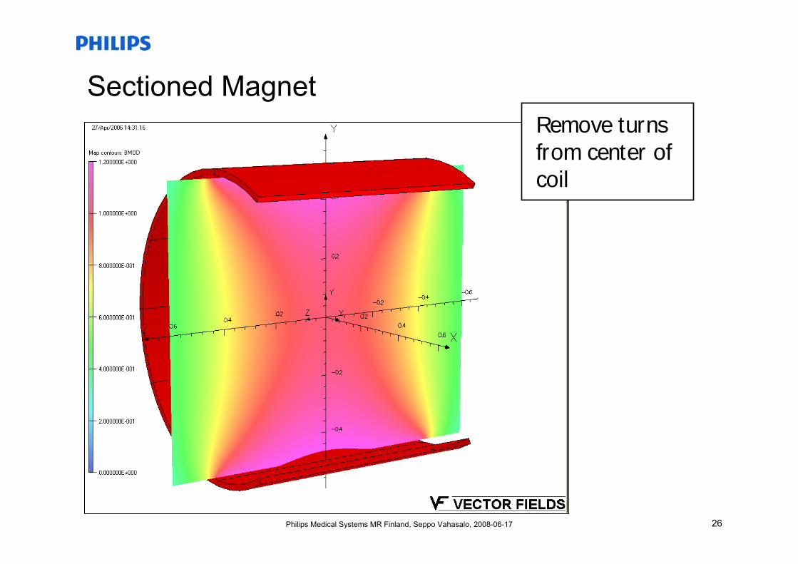
Sectioned MagnetRemove turns from center of coil
27Philips Medical Systems MR Finland, Seppo Vahasalo, 2008-06-17
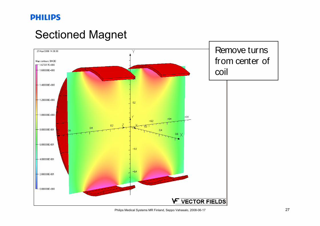
Sectioned MagnetRemove turns from center of coil
28Philips Medical Systems MR Finland, Seppo Vahasalo, 2008-06-17
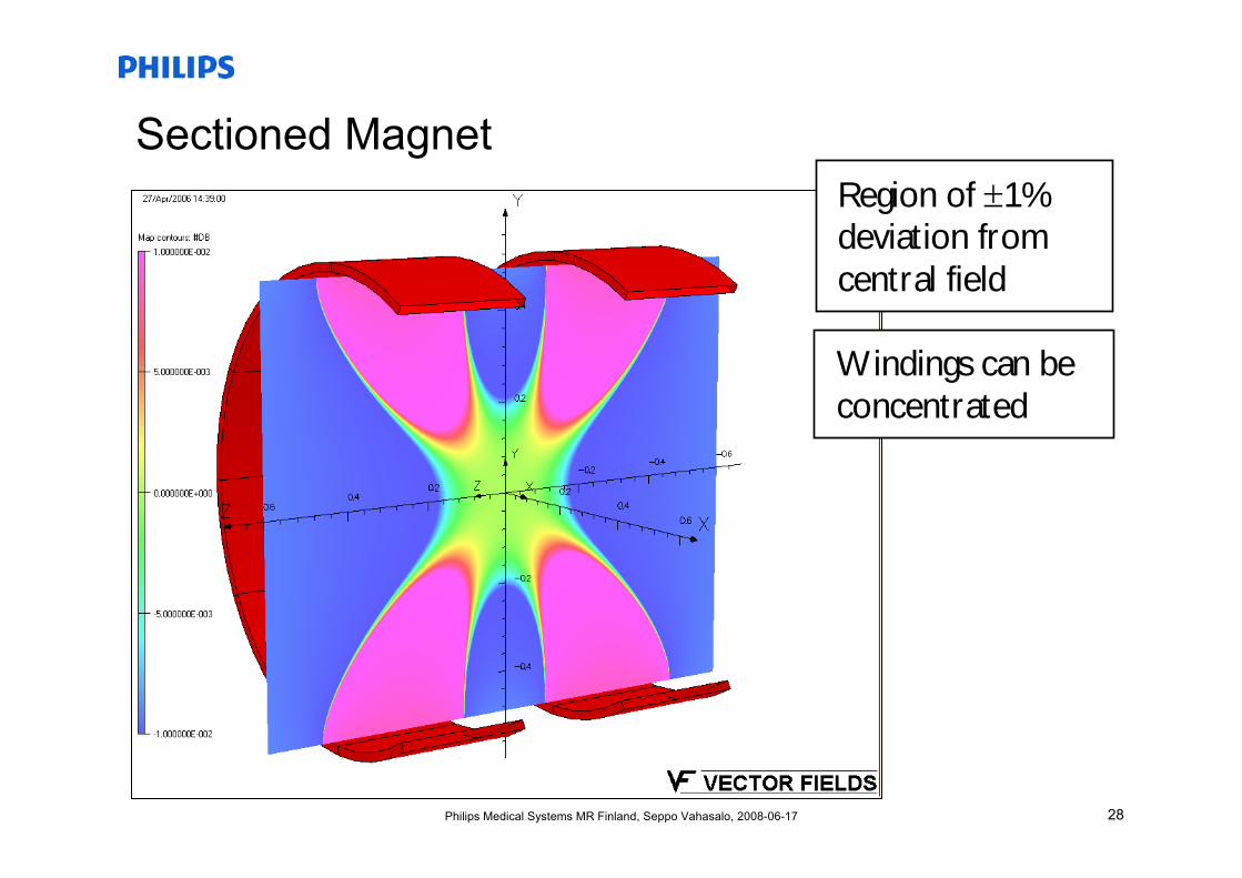
Sectioned Magnet
Windings can be concentrated
Region of ±1% deviation from central field
29Philips Medical Systems MR Finland, Seppo Vahasalo, 2008-06-17
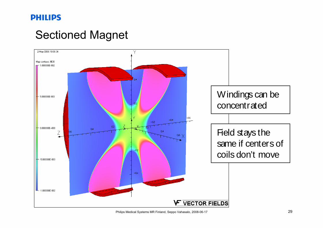
Sectioned Magnet
Windings can be concentrated
Field stays the same if centers of coils don’t move
30Philips Medical Systems MR Finland, Seppo Vahasalo, 2008-06-17
Sectioned Magnet
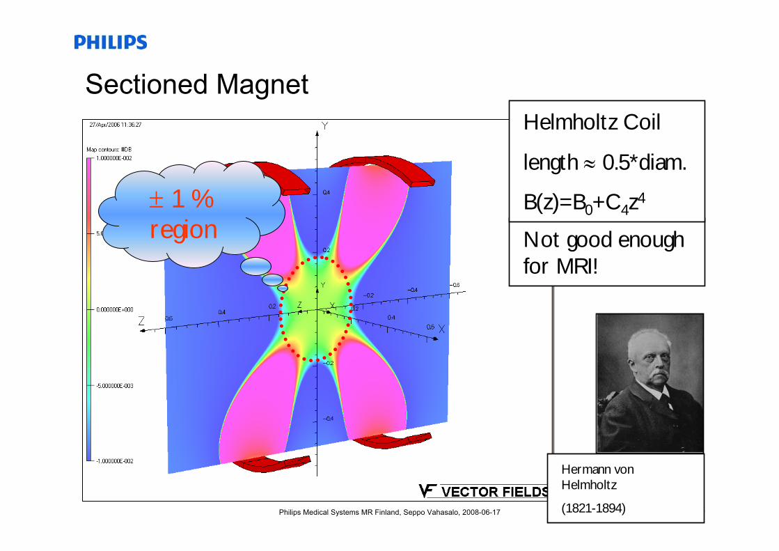
Not good enough for MRI!
± 1 % region
Helmholtz Coil
length ≈ 0.5*diam.
B(z)=B0+C4z4
Hermann von Helmholtz
(1821-1894)
31Philips Medical Systems MR Finland, Seppo Vahasalo, 2008-06-17
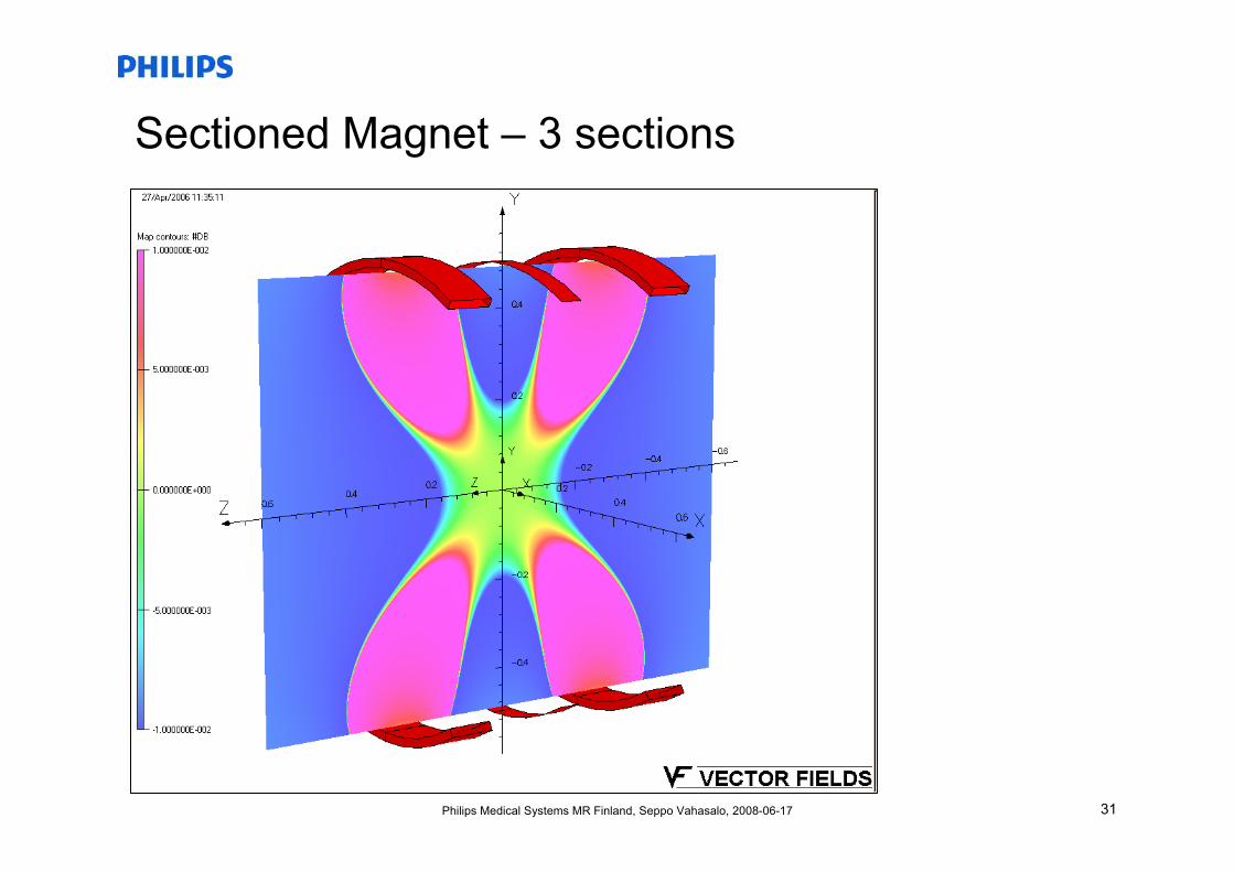
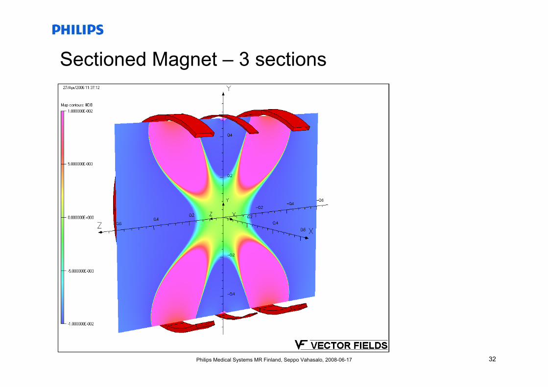
Sectioned Magnet – 3 sections
32Philips Medical Systems MR Finland, Seppo Vahasalo, 2008-06-17
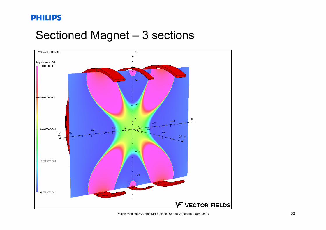
Sectioned Magnet – 3 sections
33Philips Medical Systems MR Finland, Seppo Vahasalo, 2008-06-17
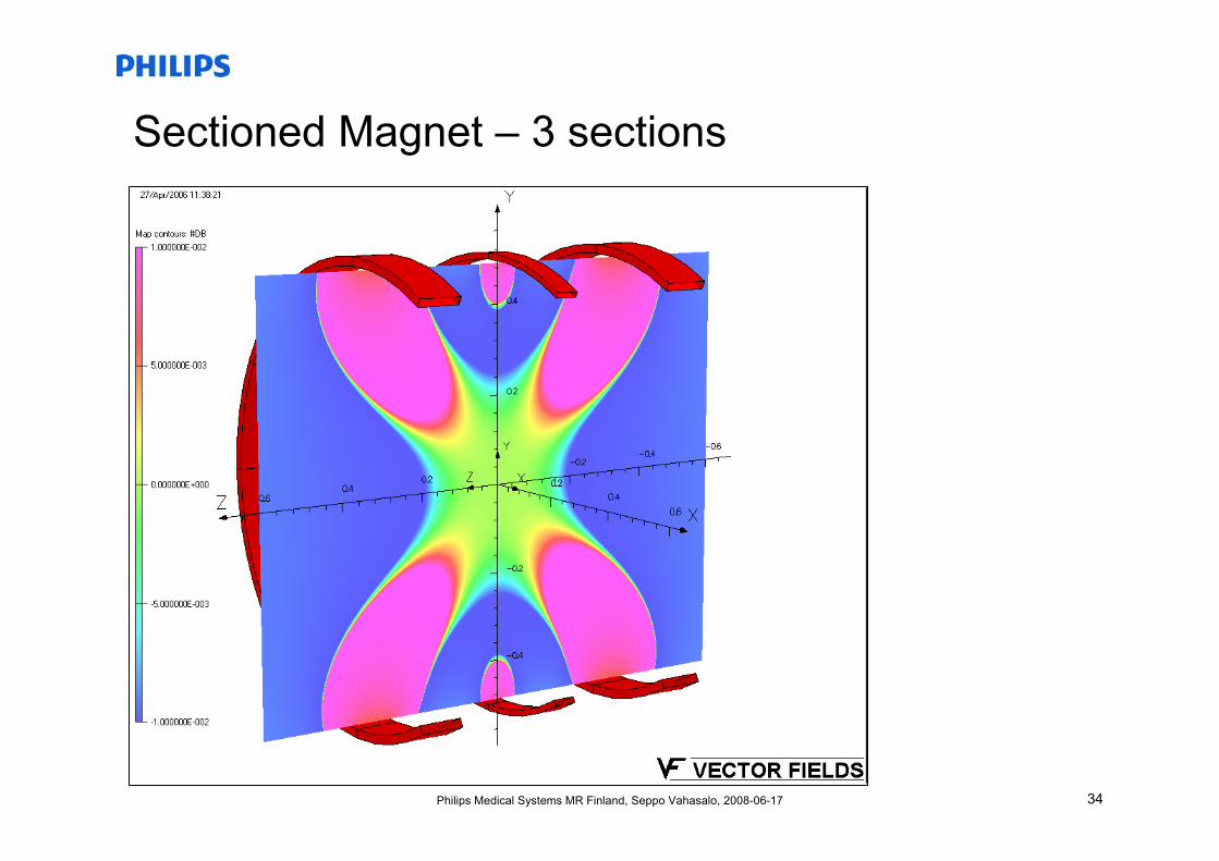
Sectioned Magnet – 3 sections
34Philips Medical Systems MR Finland, Seppo Vahasalo, 2008-06-17
Sectioned Magnet – 3 sections

35Philips Medical Systems MR Finland, Seppo Vahasalo, 2008-06-17
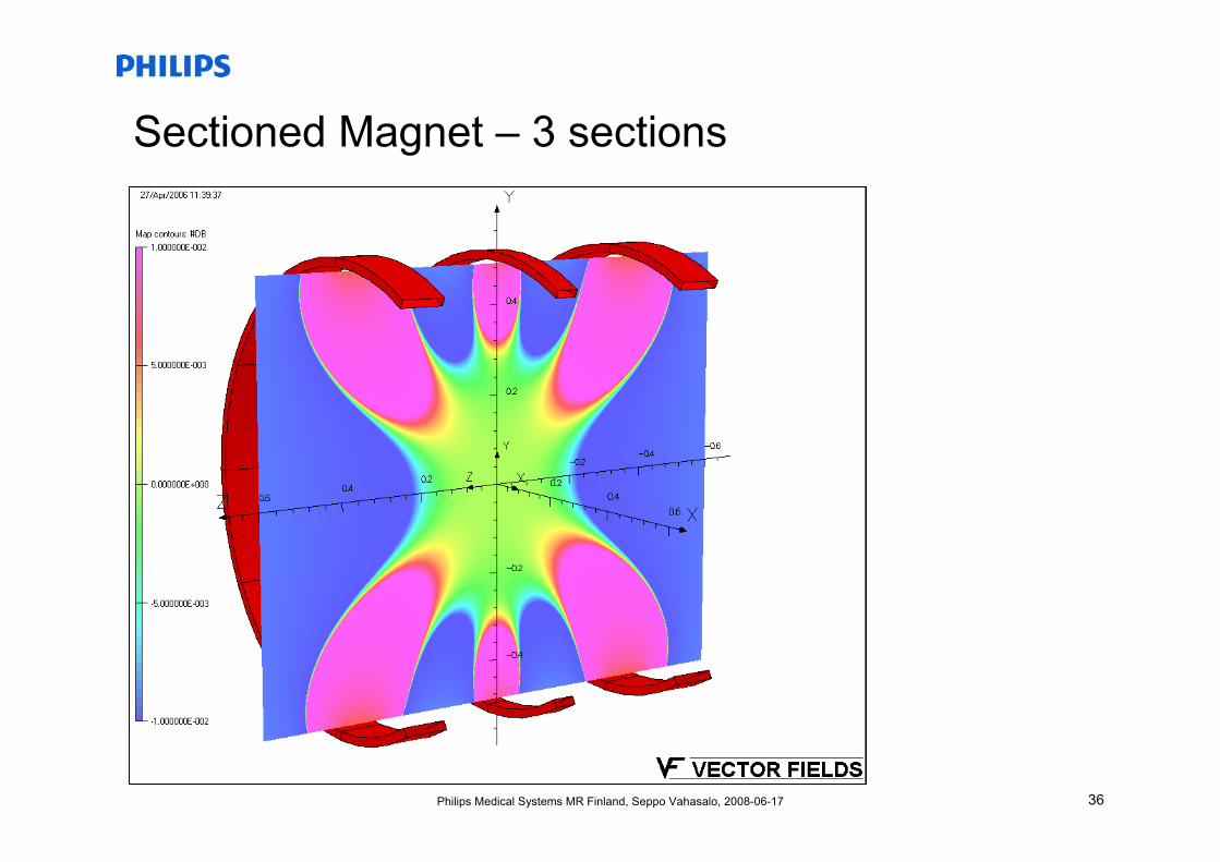
Sectioned Magnet – 3 sections
36Philips Medical Systems MR Finland, Seppo Vahasalo, 2008-06-17
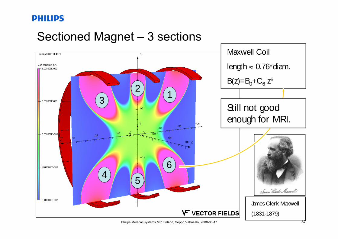
Sectioned Magnet – 3 sections
37Philips Medical Systems MR Finland, Seppo Vahasalo, 2008-06-17
Sectioned Magnet – 3 sectionsMaxwell Coil
length ≈ 0.76*diam.
B(z)=B0+C6 z6
James Clerk Maxwell
(1831-1879)
12
3
45
6
Still not good enough for MRI.
38Philips Medical Systems MR Finland, Seppo Vahasalo, 2008-06-17
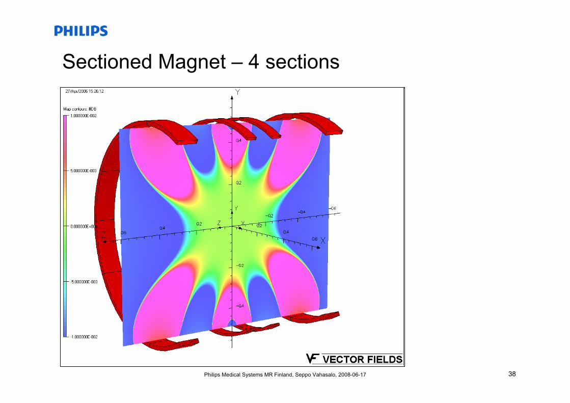
Sectioned Magnet – 4 sections

39Philips Medical Systems MR Finland, Seppo Vahasalo, 2008-06-17
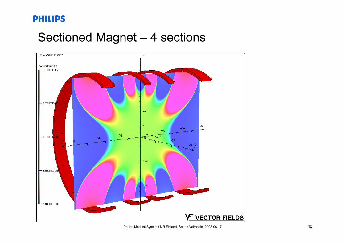
Sectioned Magnet – 4 sections
40Philips Medical Systems MR Finland, Seppo Vahasalo, 2008-06-17
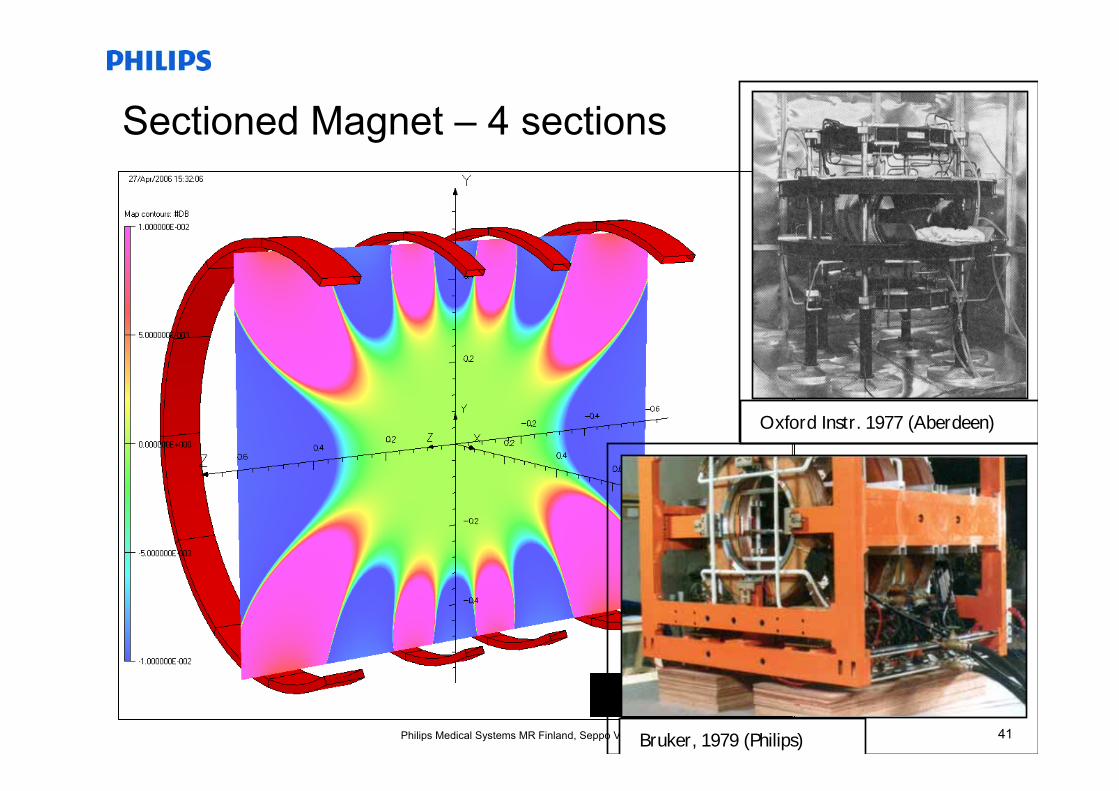
Sectioned Magnet – 4 sections
41Philips Medical Systems MR Finland, Seppo Vahasalo, 2008-06-17
Sectioned Magnet – 4 sections
Oxford Instr. 1977 (Aberdeen)
Bruker, 1979 (Philips)
42Philips Medical Systems MR Finland, Seppo Vahasalo, 2008-06-17
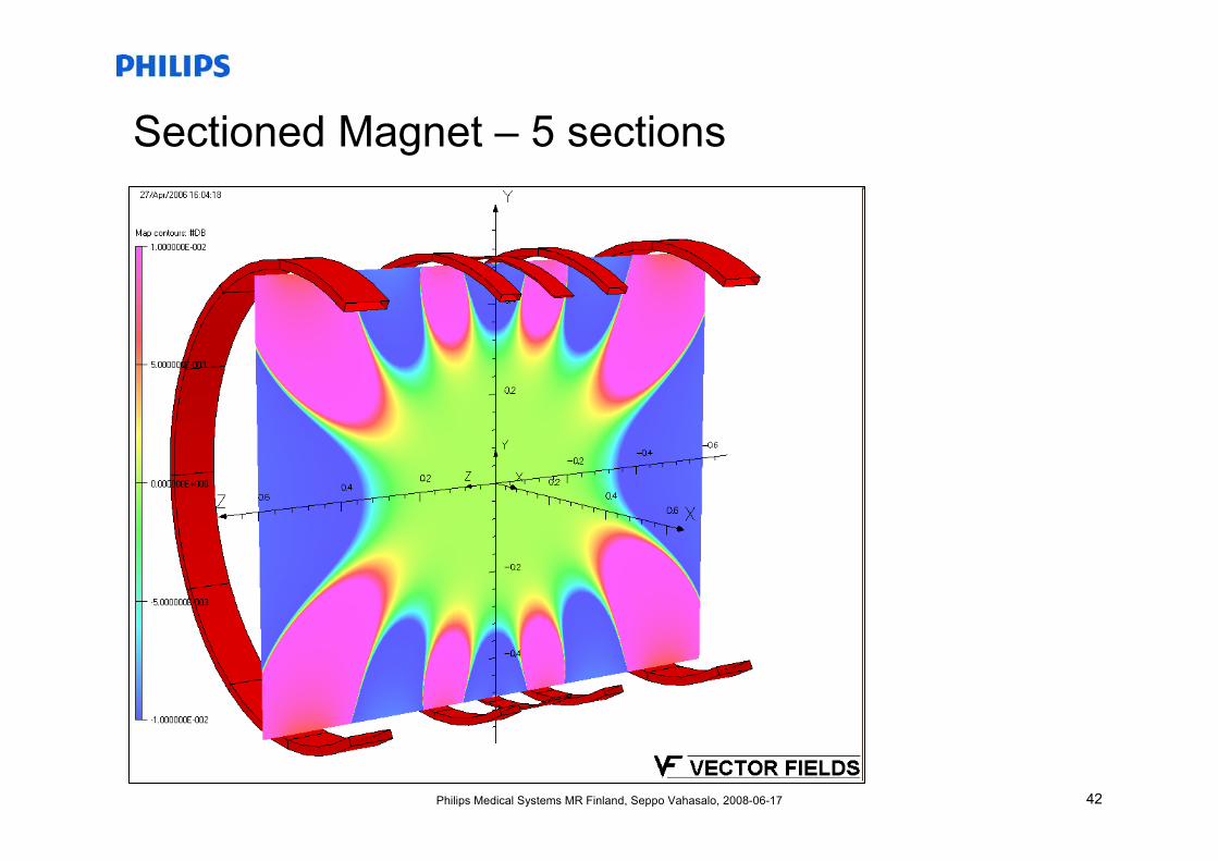
Sectioned Magnet – 5 sections
43Philips Medical Systems MR Finland, Seppo Vahasalo, 2008-06-17
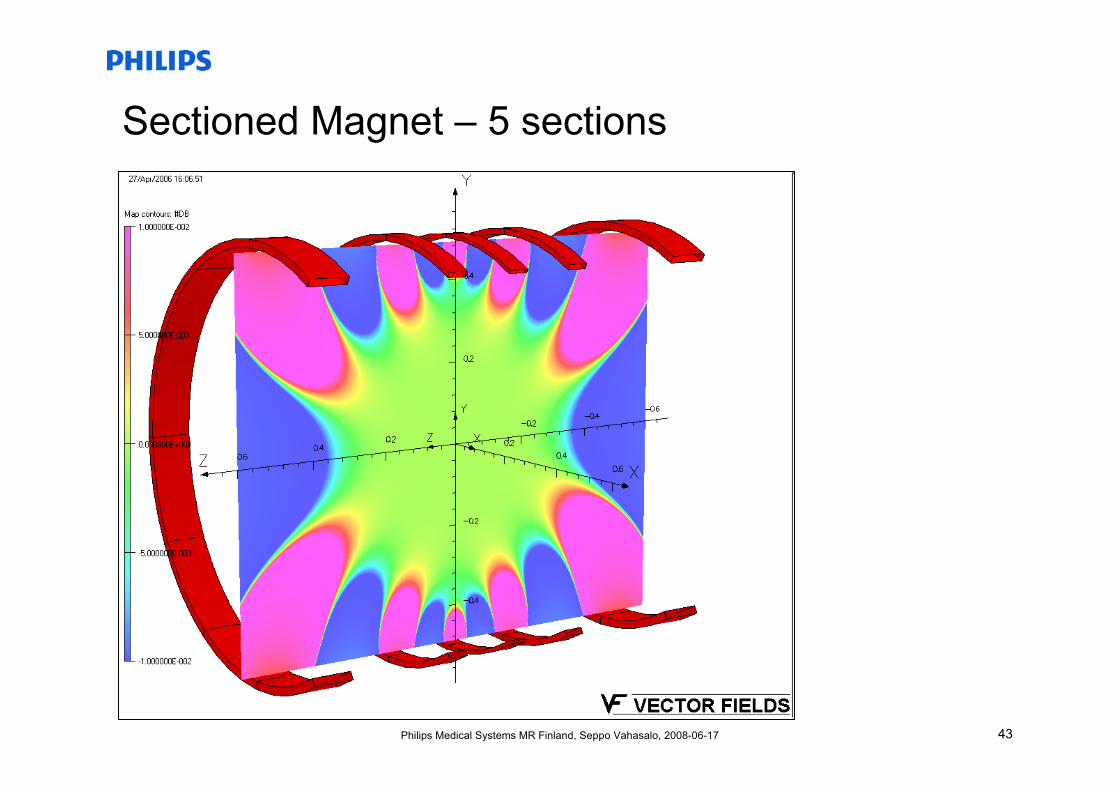
Sectioned Magnet – 5 sections
44Philips Medical Systems MR Finland, Seppo Vahasalo, 2008-06-17
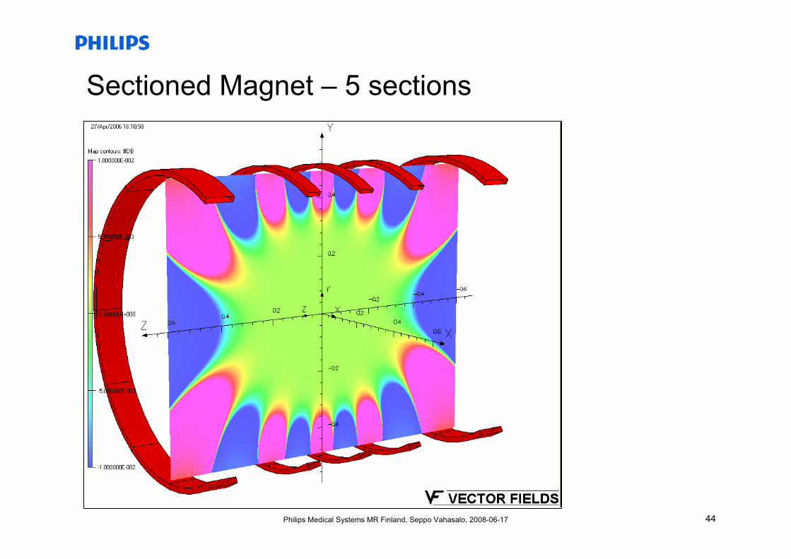
Sectioned Magnet – 5 sections
45Philips Medical Systems MR Finland, Seppo Vahasalo, 2008-06-17
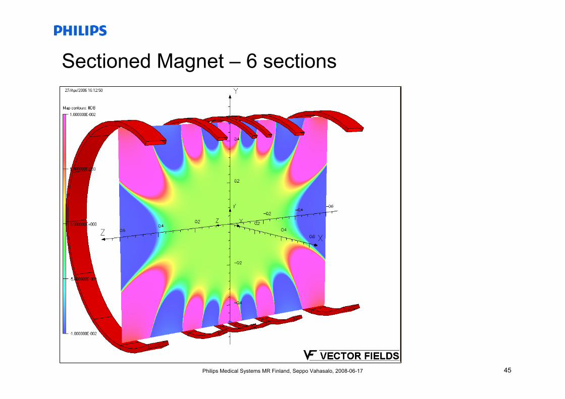
Sectioned Magnet – 6 sections
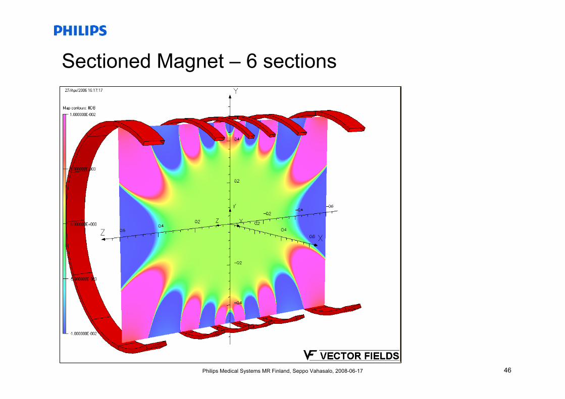
46Philips Medical Systems MR Finland, Seppo Vahasalo, 2008-06-17
Sectioned Magnet – 6 sections
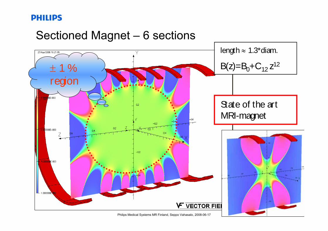
47Philips Medical Systems MR Finland, Seppo Vahasalo, 2008-06-17
Sectioned Magnet – 6 sectionslength ≈ 1.3*diam.
B(z)=B0+C12 z12
State of the art MRI-magnet
± 1 % region
48Philips Medical Systems MR Finland, Seppo Vahasalo, 2008-06-17
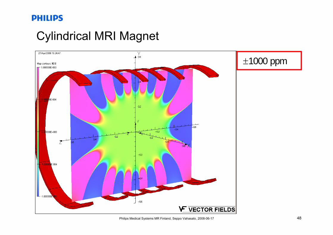
Cylindrical MRI Magnet
±1000 ppm
49Philips Medical Systems MR Finland, Seppo Vahasalo, 2008-06-17
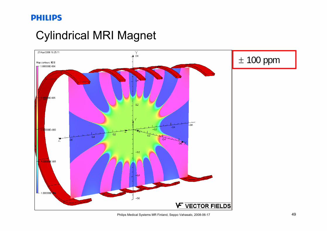
Cylindrical MRI Magnet
± 100 ppm
50Philips Medical Systems MR Finland, Seppo Vahasalo, 2008-06-17
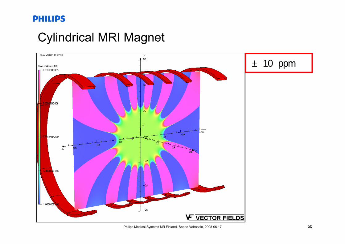
Cylindrical MRI Magnet
± 10 ppm
51Philips Medical Systems MR Finland, Seppo Vahasalo, 2008-06-17
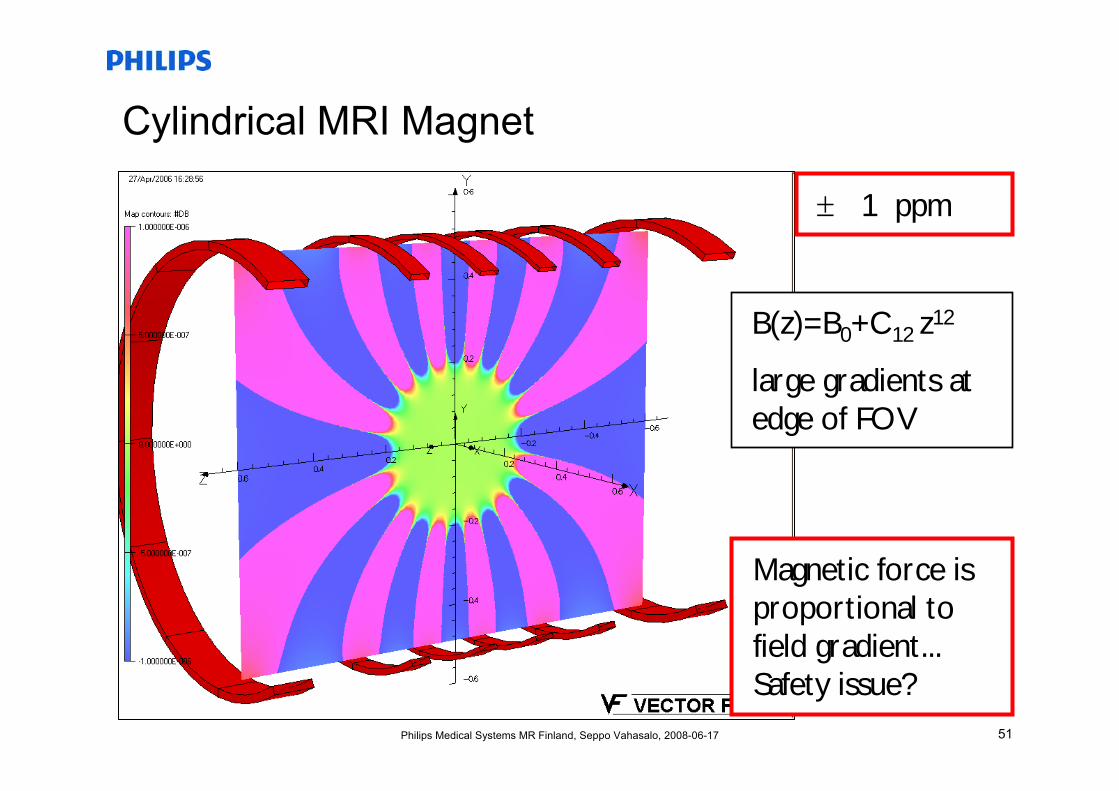
Cylindrical MRI Magnet
± 1 ppm
B(z)=B0+C12 z12
large gradients at edge of FOV
Magnetic force isproportional to field gradient... Safety issue?
52Philips Medical Systems MR Finland, Seppo Vahasalo, 2008-06-17
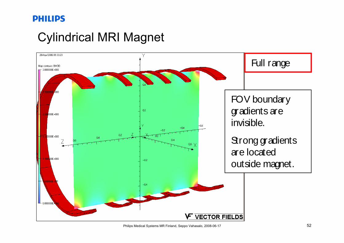
Cylindrical MRI Magnet
Full range
FOV boundary gradients are invisible.
Strong gradients are located outside magnet.
53Philips Medical Systems MR Finland, Seppo Vahasalo, 2008-06-17
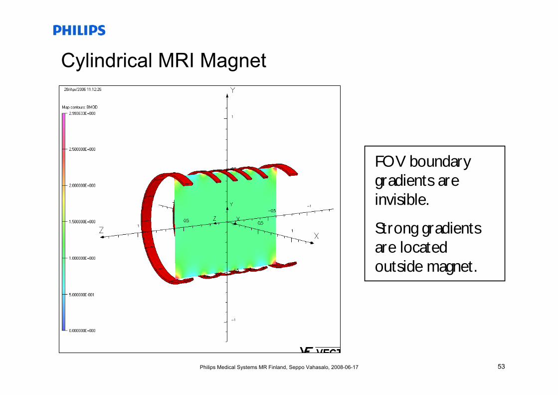
Cylindrical MRI Magnet
FOV boundary gradients are invisible.
Strong gradients are located outside magnet.
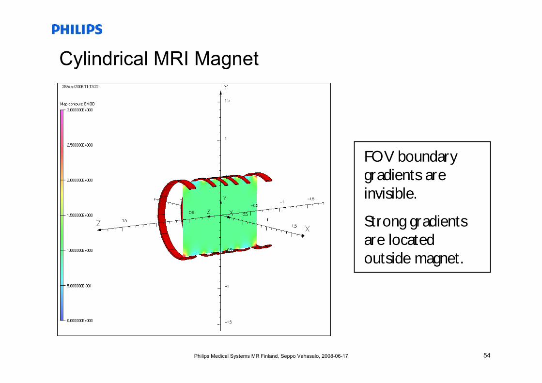
54Philips Medical Systems MR Finland, Seppo Vahasalo, 2008-06-17
Cylindrical MRI Magnet
FOV boundary gradients are invisible.
Strong gradients are located outside magnet.
55Philips Medical Systems MR Finland, Seppo Vahasalo, 2008-06-17
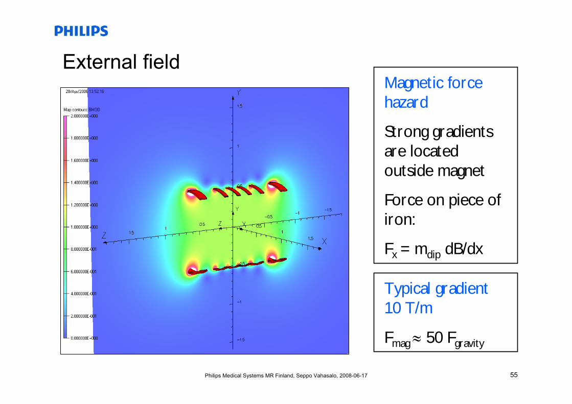
External fieldMagnetic force hazard
Strong gradients are located outside magnet
Force on piece of iron:
Fx = mdip dB/dx
Typical gradient 10 T/m
Fmag ≈ 50 Fgravity
56Philips Medical Systems MR Finland, Seppo Vahasalo, 2008-06-17
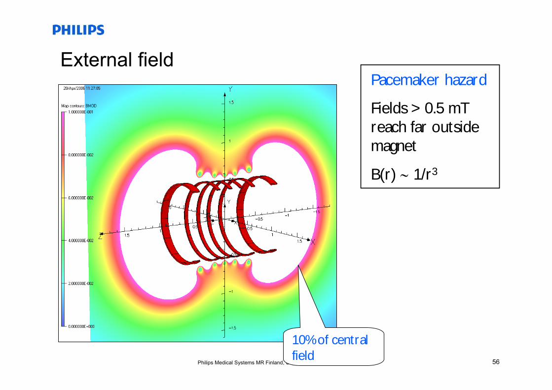
External fieldPacemaker hazard
Fields > 0.5 mTreach far outside magnet
B(r) ∼ 1/r3
10% of central field

57Philips Medical Systems MR Finland, Seppo Vahasalo, 2008-06-17
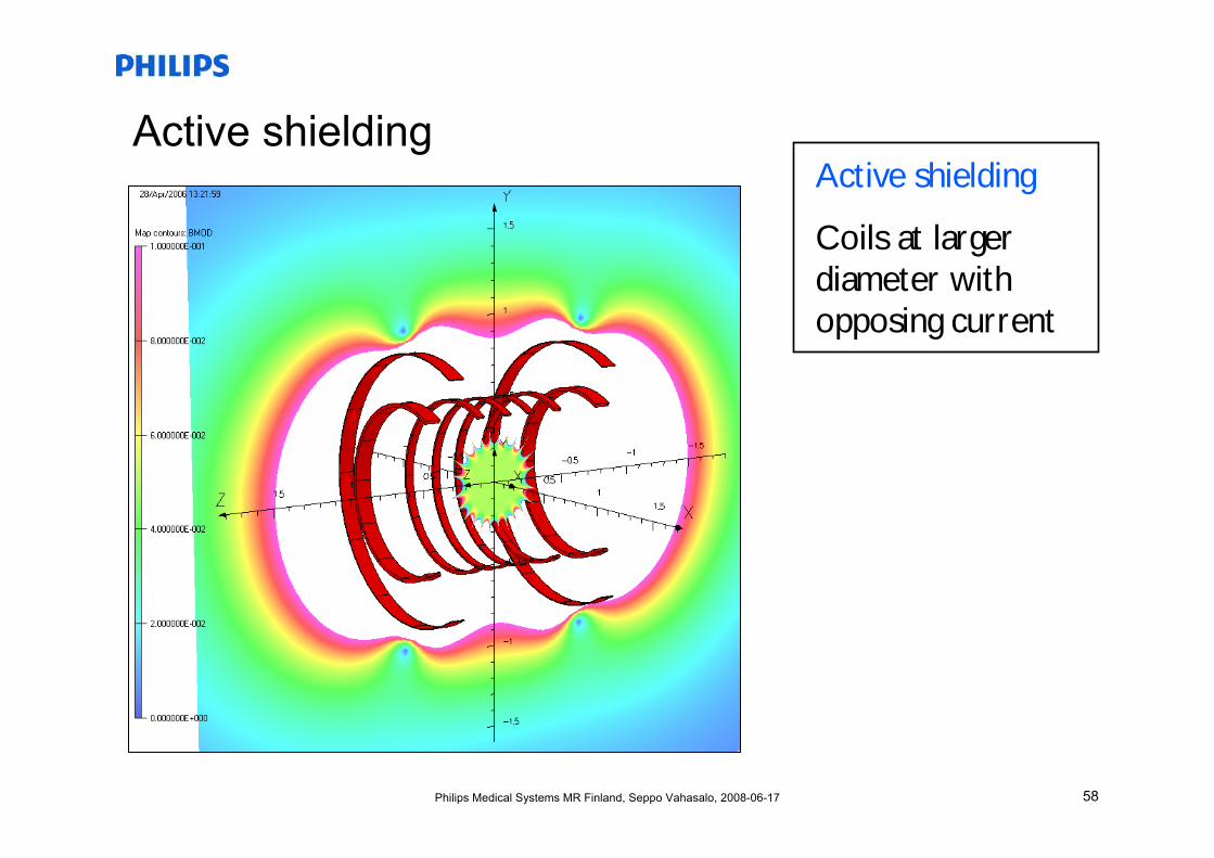
Active shieldingActive shielding
Coils at larger diameter with opposing current
Shield coil
58Philips Medical Systems MR Finland, Seppo Vahasalo, 2008-06-17
Active shieldingActive shielding
Coils at larger diameter with opposing current
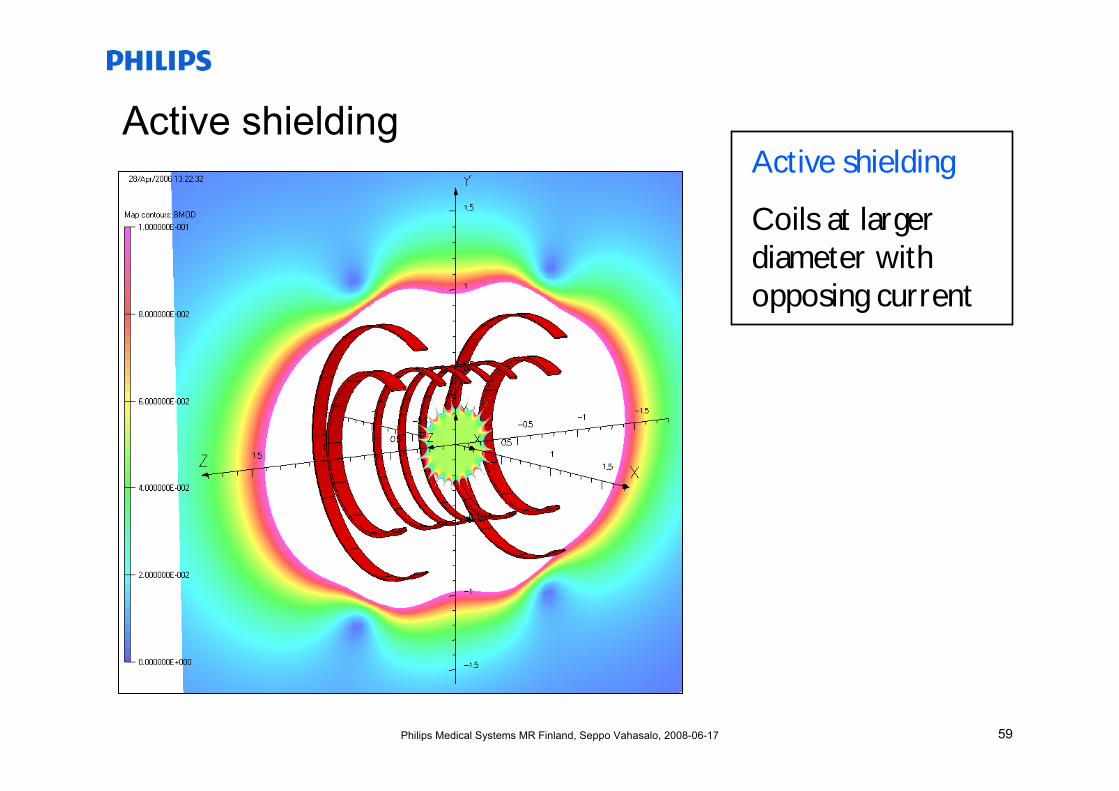
59Philips Medical Systems MR Finland, Seppo Vahasalo, 2008-06-17
Active shieldingActive shielding
Coils at larger diameter with opposing current
60Philips Medical Systems MR Finland, Seppo Vahasalo, 2008-06-17
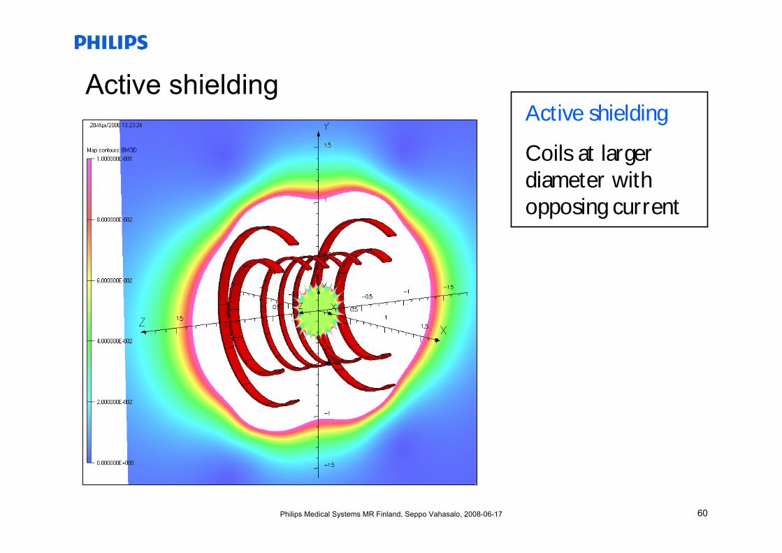
Active shieldingActive shielding
Coils at larger diameter with opposing current
61Philips Medical Systems MR Finland, Seppo Vahasalo, 2008-06-17
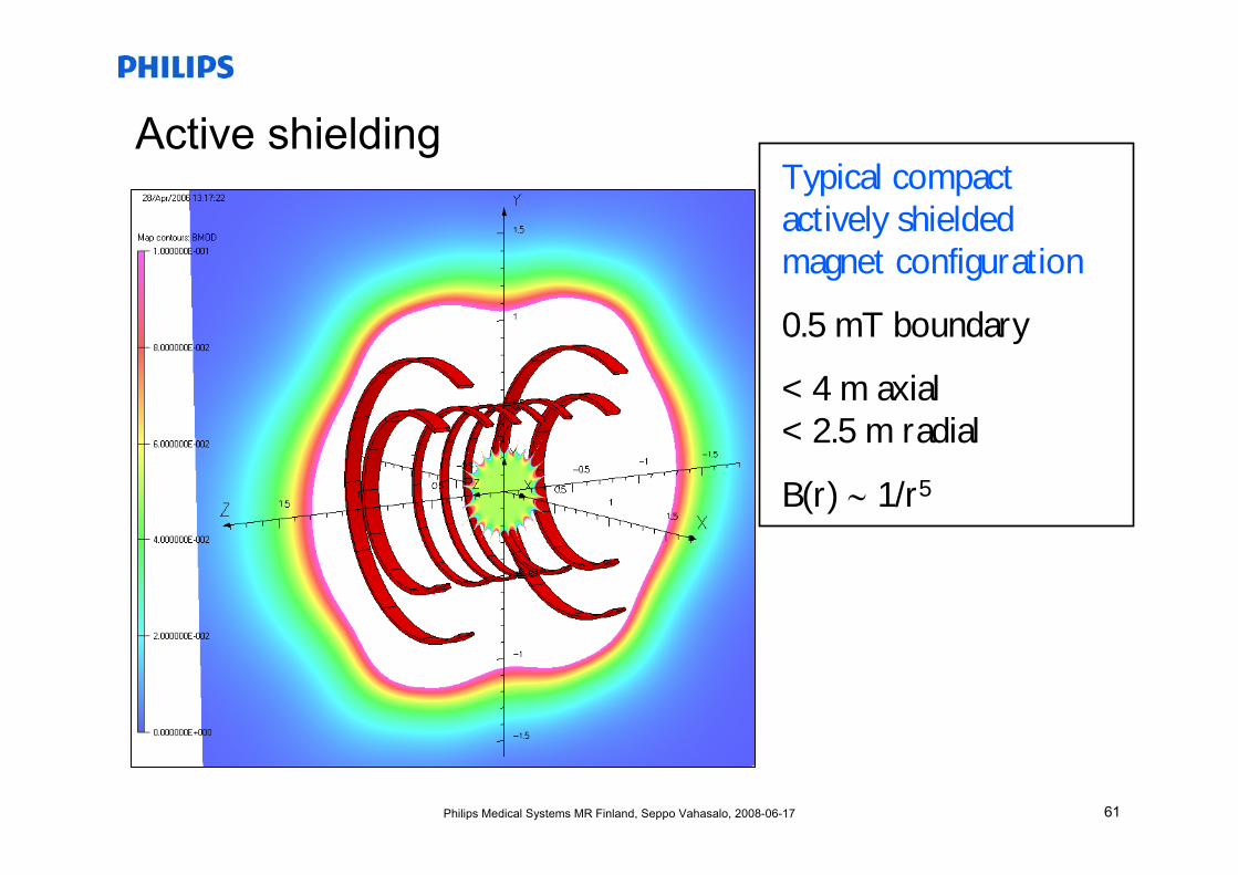
Active shieldingTypical compact actively shielded magnet configuration
0.5 mT boundary
< 4 m axial< 2.5 m radial
B(r) ∼ 1/r5
62Philips Medical Systems MR Finland, Seppo Vahasalo, 2008-06-17
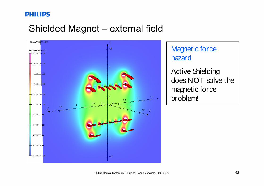
Shielded Magnet – external field
Magnetic force hazard
Active Shielding does NOT solve the magnetic force problem!
63Philips Medical Systems MR Finland, Seppo Vahasalo, 2008-06-17
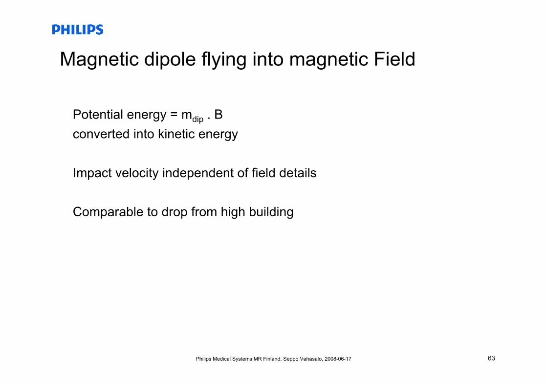
Magnetic dipole flying into magnetic Field
Potential energy = mdip . Bconverted into kinetic energy
Impact velocity independent of field details
Comparable to drop from high building
64Philips Medical Systems MR Finland, Seppo Vahasalo, 2008-06-17
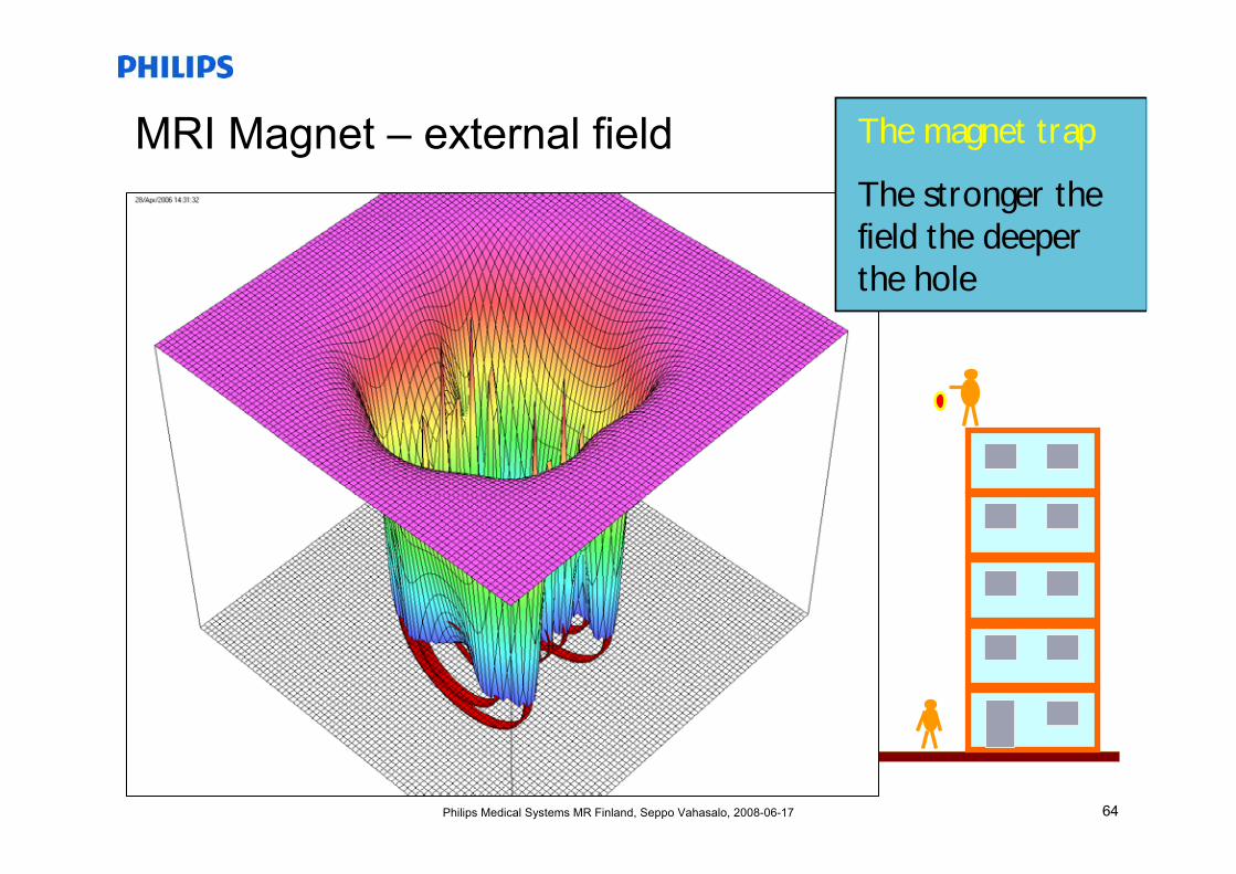
MRI Magnet – external field The magnet trap
The stronger the field the deeper the hole
65Philips Medical Systems MR Finland, Seppo Vahasalo, 2008-06-17
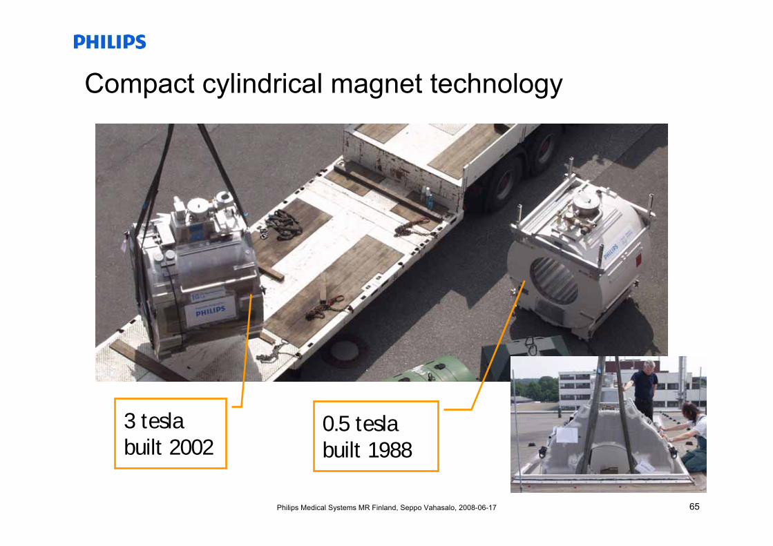
Compact cylindrical magnet technology
3 tesla built 2002
0.5 tesla built 1988
66Philips Medical Systems MR Finland, Seppo Vahasalo, 2008-06-17
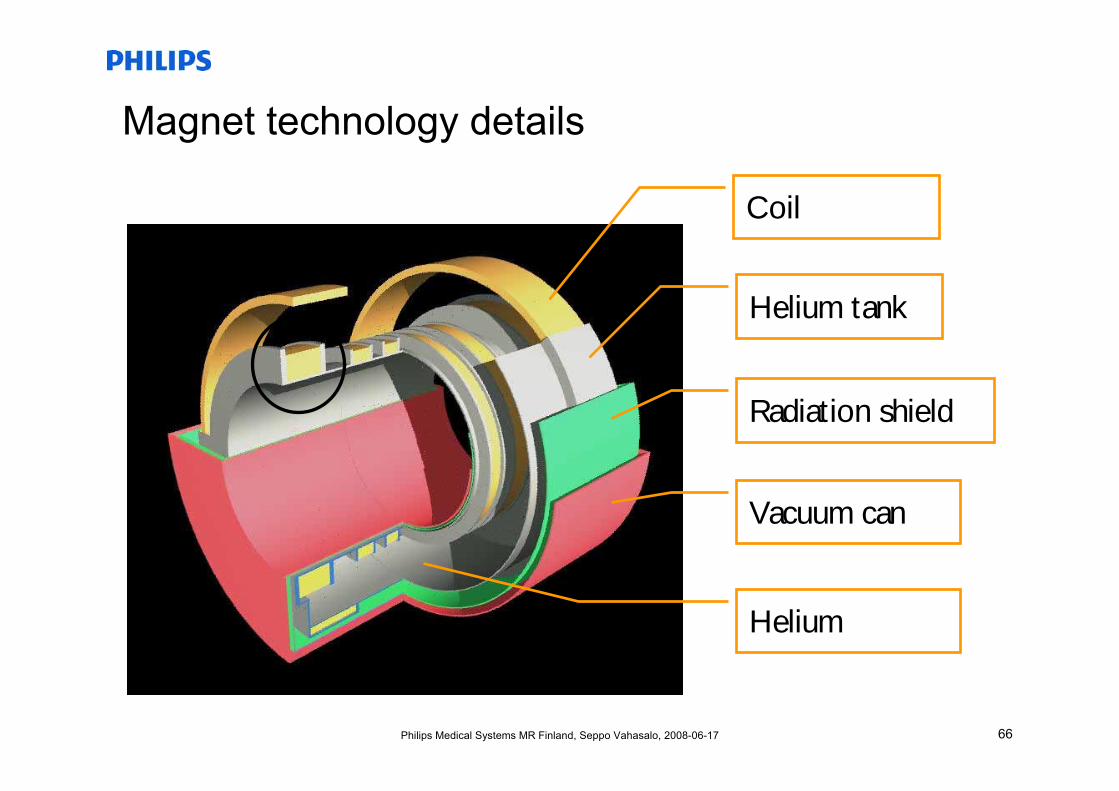
Magnet technology details
Helium tank
Coil
Radiation shield
Vacuum can
Helium
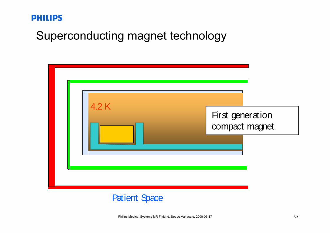
67Philips Medical Systems MR Finland, Seppo Vahasalo, 2008-06-17
Superconducting magnet technology
4.2 K
Patient Space
First generation compact magnet
68Philips Medical Systems MR Finland, Seppo Vahasalo, 2008-06-17
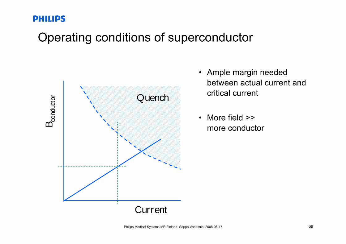
Operating conditions of superconductor
• Ample margin needed between actual current and critical current
• More field >>more conductor
Current
B con
duct
or Quench
69Philips Medical Systems MR Finland, Seppo Vahasalo, 2008-06-17
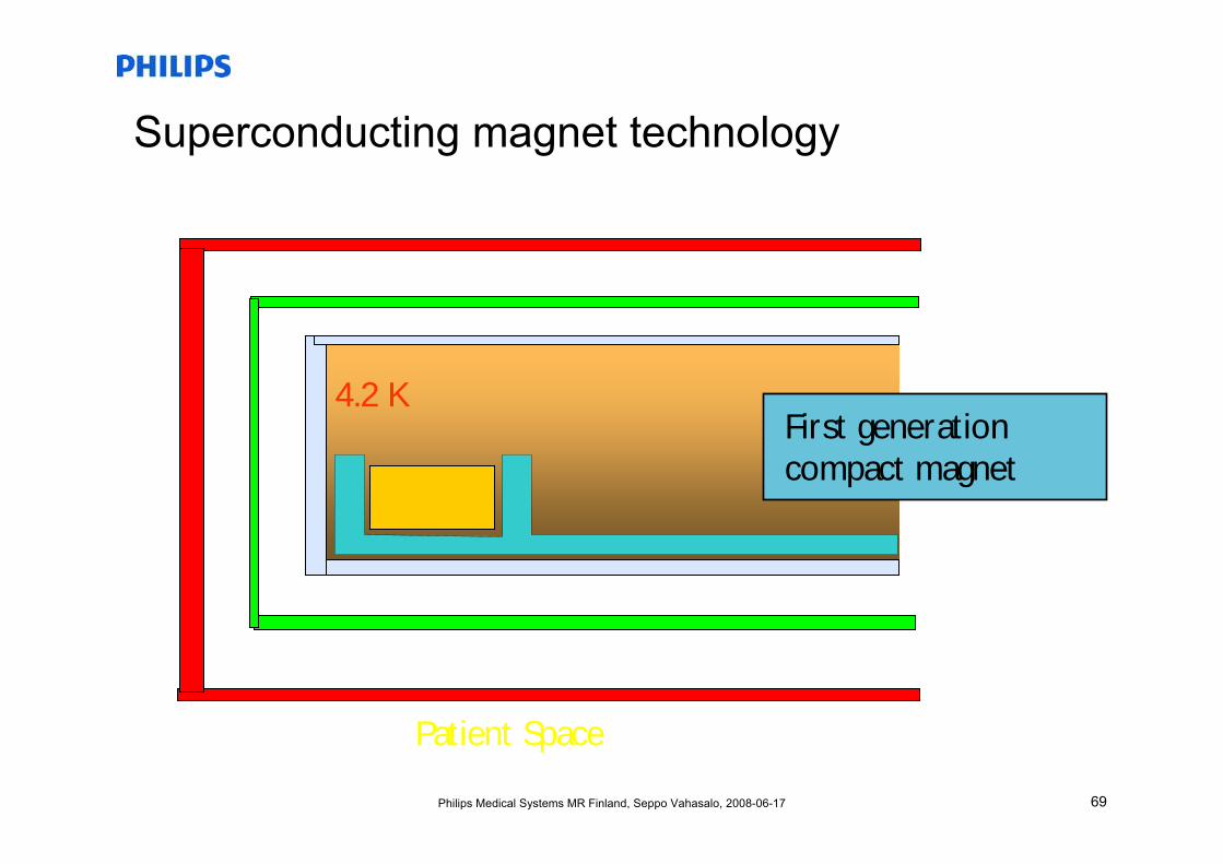
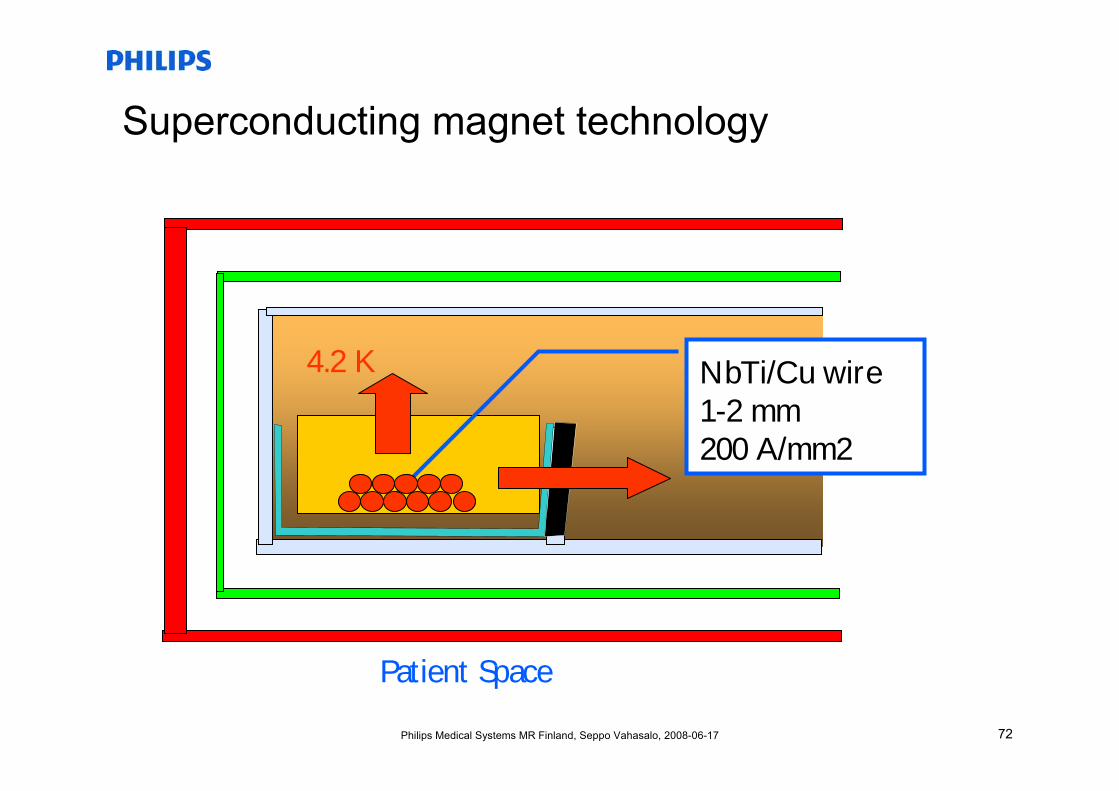
Superconducting magnet technology
4.2 K
Patient Space
First generation compact magnet
70Philips Medical Systems MR Finland, Seppo Vahasalo, 2008-06-17
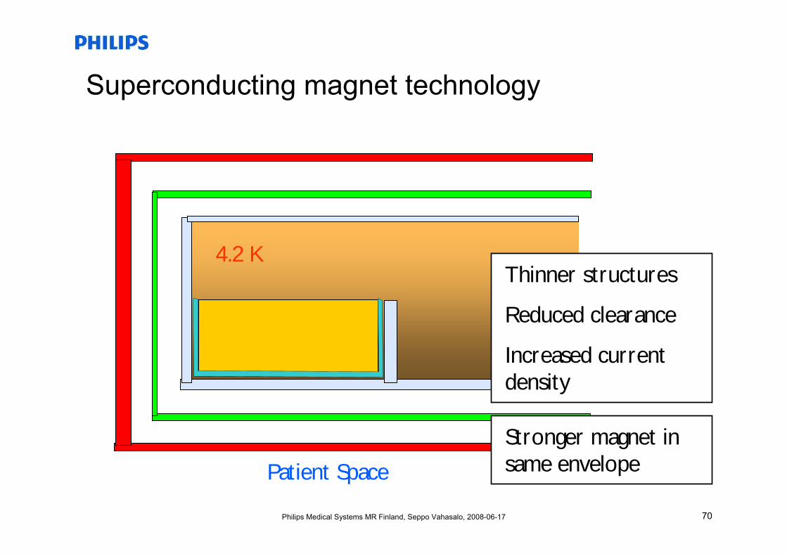
Superconducting magnet technology
4.2 K
Patient Space
Thinner structures
Reduced clearance
Increased current density
Stronger magnet in same envelope
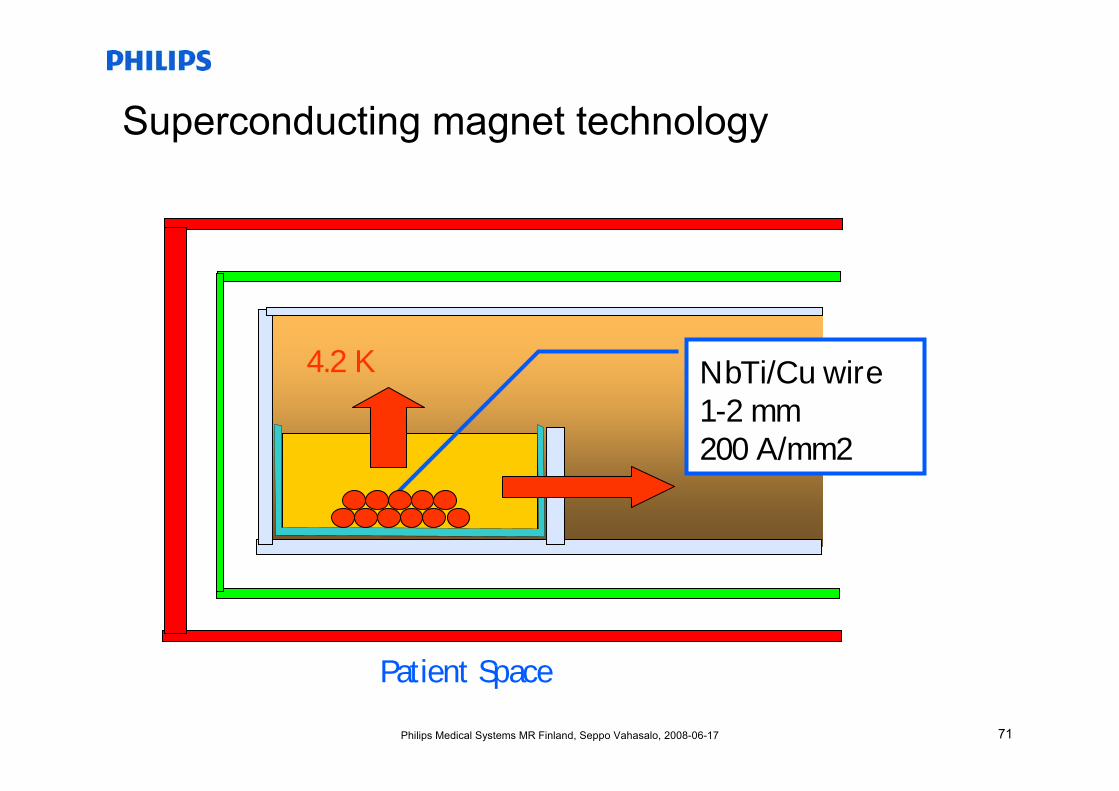
71Philips Medical Systems MR Finland, Seppo Vahasalo, 2008-06-17
Superconducting magnet technology
NbTi/Cu wire1-2 mm200 A/mm2
4.2 K
Patient Space
72Philips Medical Systems MR Finland, Seppo Vahasalo, 2008-06-17
Superconducting magnet technology
NbTi/Cu wire1-2 mm200 A/mm2
4.2 K
Patient Space
73Philips Medical Systems MR Finland, Seppo Vahasalo, 2008-06-17
High temperature superconductors and MRI
• Problems with HTC superconductors in MRI are– Maximum current density, maximum critical flux density– Limited length of available wires-> At the moment not cost effective
• We have done a feasibility study for a 0.6T HTC iron core MRI magnet– Possible to build– With the extrapolated developments (improvements in current/flux
density, reductions in price) will be viable soon, but ..– Trend is towards higher field strengths, so this design does not
make sense commercially
74Philips Medical Systems MR Finland, Seppo Vahasalo, 2008-06-17
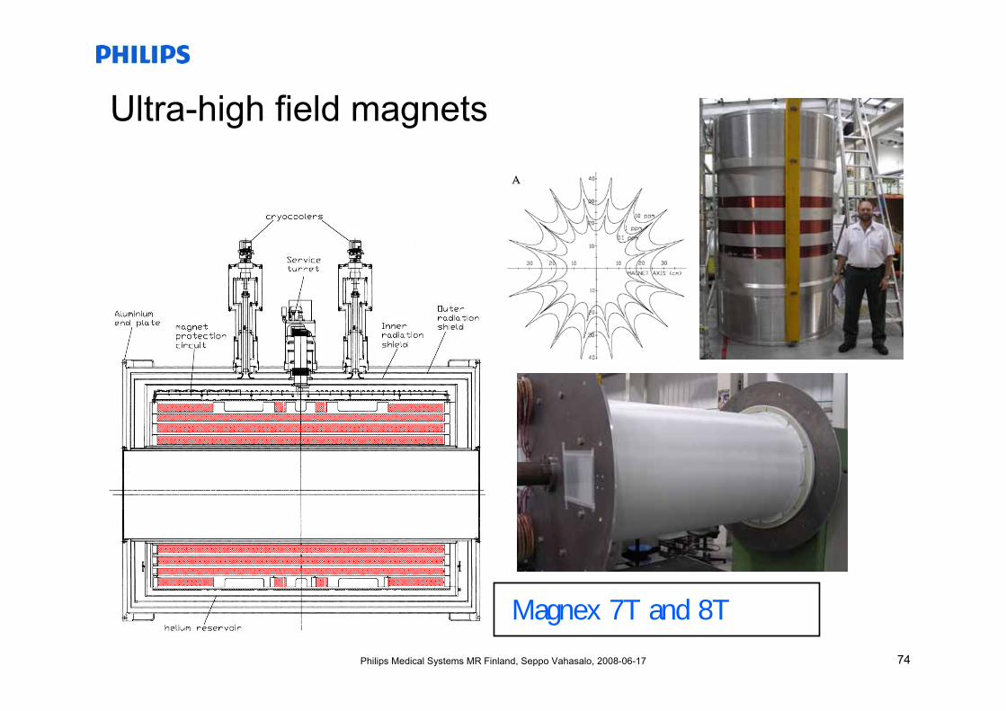
Ultra-high field magnets
Magnex 7T and 8T
75Philips Medical Systems MR Finland, Seppo Vahasalo, 2008-06-17
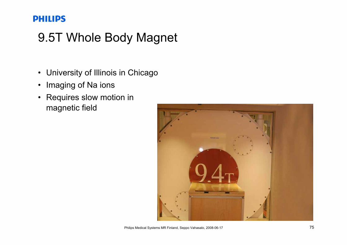
9.5T Whole Body Magnet
• University of Illinois in Chicago• Imaging of Na ions• Requires slow motion in
magnetic field
76Philips Medical Systems MR Finland, Seppo Vahasalo, 2008-06-17
Cost aspect of Ultra-high field magnets
• Rule of thumb: system cost is about $1 million/T up to 7T systems– 1.5T system cost $1.5M
• The rule applies up to 7T, after that exponential growth of cost• A 7T system
– Has some 420 kilometers of superconducting wire– Weighs about 30 tons– Requires about 440 tons of steel around magnet for stray field
shielding• From 7T to 9.4T add about $8M• Above 10T the cost is about $10M/T, so a 15T system would cost
$150 million• In France plans to build a 11.7T whole body magnet
77Philips Medical Systems MR Finland, Seppo Vahasalo, 2008-06-17
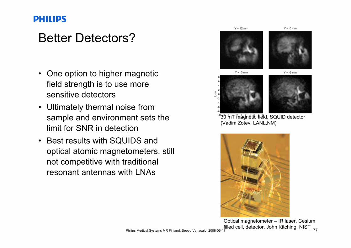
Better Detectors?
• One option to higher magneticfield strength is to use moresensitive detectors
• Ultimately thermal noise from sample and environment sets the limit for SNR in detection
• Best results with SQUIDS and optical atomic magnetometers, still not competitive with traditional resonant antennas with LNAs
30 mT magnetic field, SQUID detector(Vadim Zotev, LANL,NM)
Optical magnetometer – IR laser, Cesiumfilled cell, detector. John Kitching, NIST
78Philips Medical Systems MR Finland, Seppo Vahasalo, 2008-06-17
Key properties of cylindrical MRI magnets
• Field generation:• Field shaping:• Stray-field containment:
Coils
Coils
Coils
Enclosed in cryostat with liquid heliumL/D ratio > 1.5Common architecture up to 3 Tesla
Unshielded long coils for 7T and more
79Philips Medical Systems MR Finland, Seppo Vahasalo, 2008-06-17
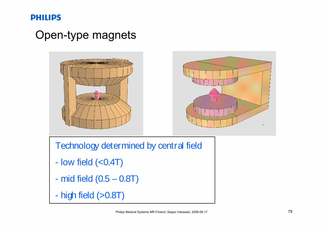
Open-type magnets
Technology determined by central field
- low field (<0.4T)
- mid field (0.5 – 0.8T)
- high field (>0.8T)
80Philips Medical Systems MR Finland, Seppo Vahasalo, 2008-06-17
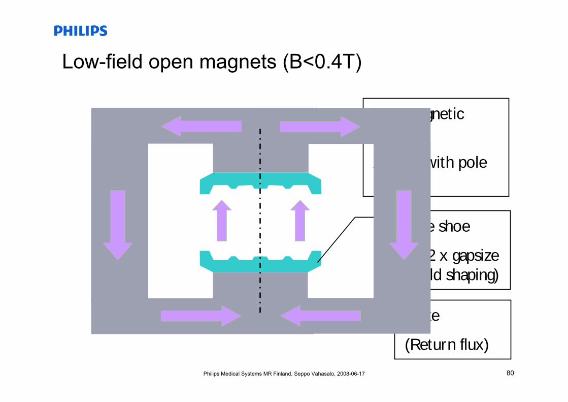
Low-field open magnets (B<0.4T)
Iron magnetic circuit
Air gap with pole shoes
Pole shoe
D>2 x gapsize(Field shaping)
Yoke
(Return flux)
81Philips Medical Systems MR Finland, Seppo Vahasalo, 2008-06-17
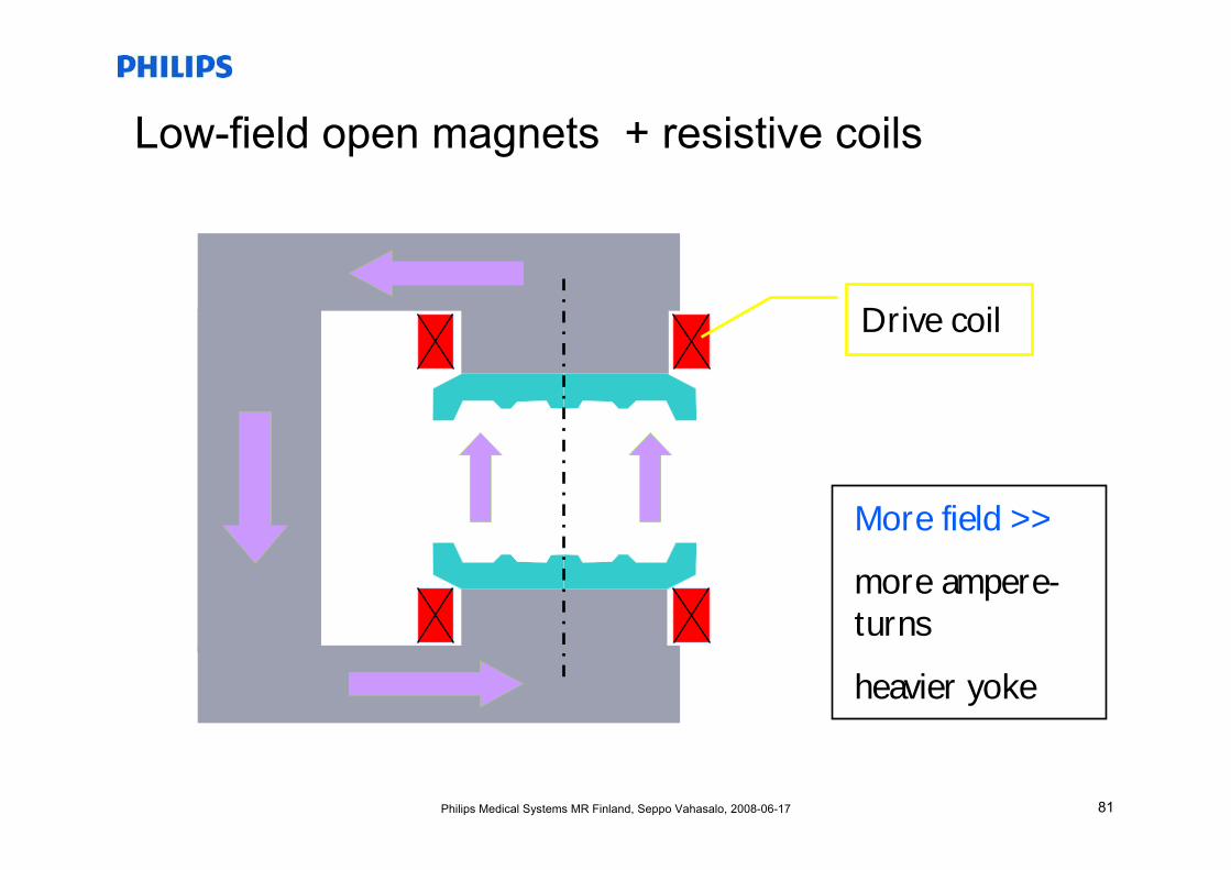
Low-field open magnets + resistive coils
Drive coil
More field >>
more ampere-turns
heavier yoke
82Philips Medical Systems MR Finland, Seppo Vahasalo, 2008-06-17
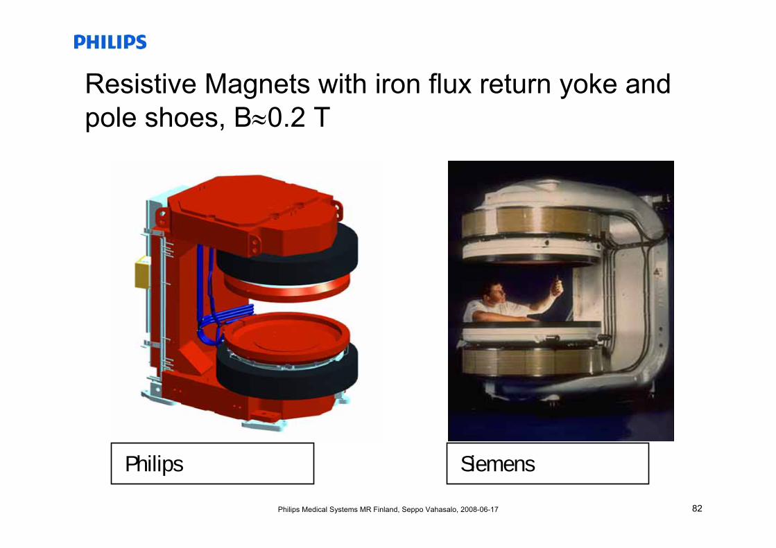
Resistive Magnets with iron flux return yoke and pole shoes, B≈0.2 T
Philips Siemens
83Philips Medical Systems MR Finland, Seppo Vahasalo, 2008-06-17
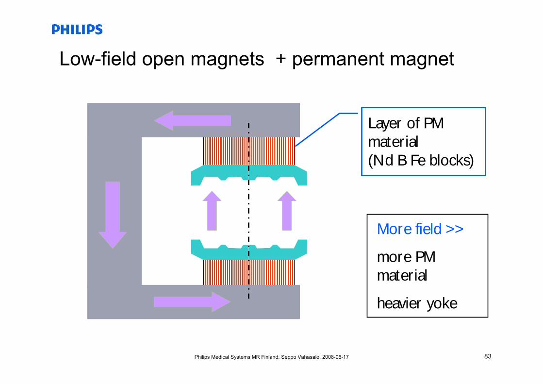
Low-field open magnets + permanent magnet
Layer of PM material(Nd B Fe blocks)
More field >>
more PM material
heavier yoke
84Philips Medical Systems MR Finland, Seppo Vahasalo, 2008-06-17
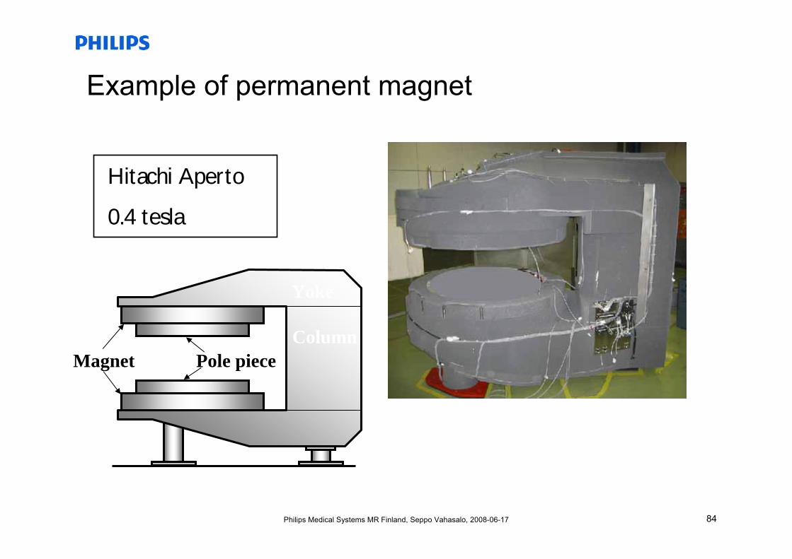
Example of permanent magnet
Hitachi Aperto
0.4 tesla
Magnet Pole piece
Yoke
Column
85Philips Medical Systems MR Finland, Seppo Vahasalo, 2008-06-17
Limits of yoke/pole configuration
• Power dissipation of resistive magnet too large• Permanent magnet material cost explodes• Magnetic saturation of pole iron
• For B > 0.5T use superconducting drive coils• Field shaping with iron rings
86Philips Medical Systems MR Finland, Seppo Vahasalo, 2008-06-17
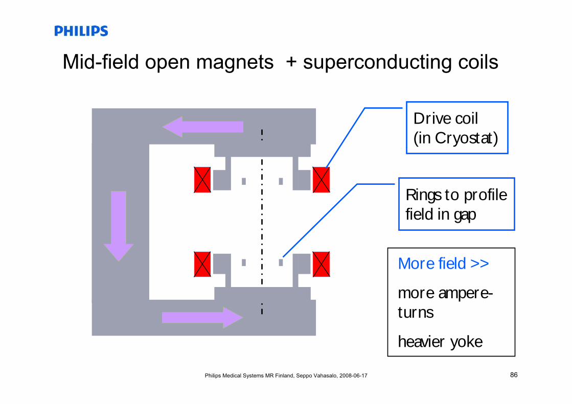
Mid-field open magnets + superconducting coils
Drive coil(in Cryostat)
More field >>
more ampere-turns
heavier yoke
Rings to profile field in gap
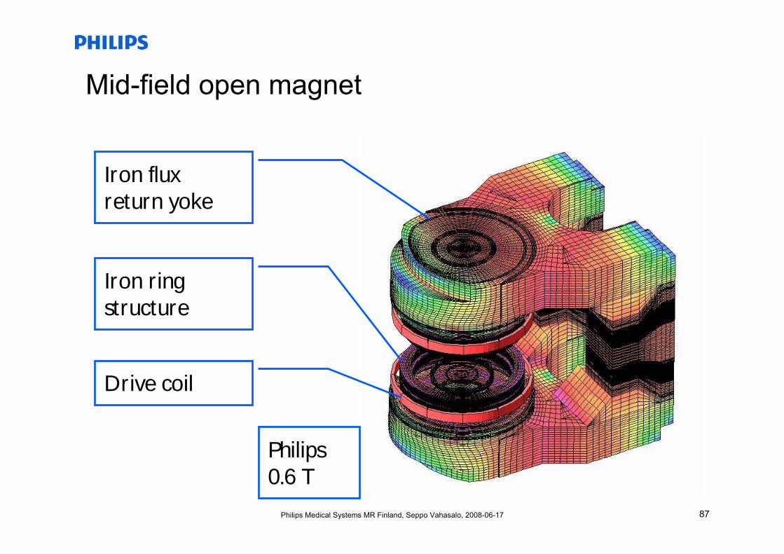
87Philips Medical Systems MR Finland, Seppo Vahasalo, 2008-06-17
Mid-field open magnet
Philips 0.6 T
Drive coil
Iron ring structure
Iron flux return yoke
88Philips Medical Systems MR Finland, Seppo Vahasalo, 2008-06-17
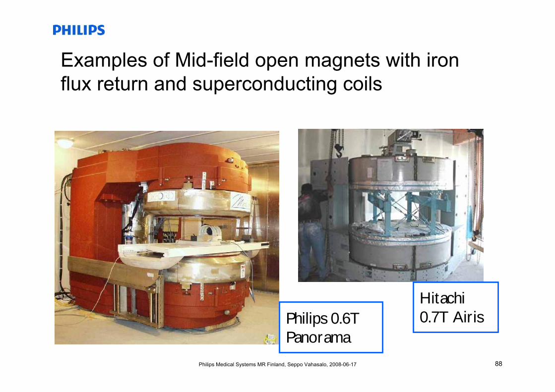
Examples of Mid-field open magnets with iron flux return and superconducting coils
Philips 0.6T Panorama
Hitachi 0.7T Airis
89Philips Medical Systems MR Finland, Seppo Vahasalo, 2008-06-17
Iron-less superconducting high-field open magnets• Weight of yoke becomes prohibitive at >1 tesla
(≈40 tons at ≈ 0.7 tesla).
• Fully superconducting coil system for field generation and field shaping
• External field cancelled by active shield coils
90Philips Medical Systems MR Finland, Seppo Vahasalo, 2008-06-17
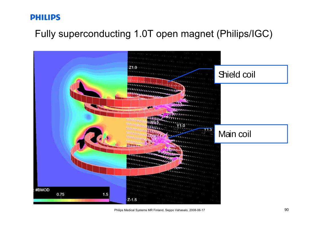
Fully superconducting 1.0T open magnet (Philips/IGC)
Main coil
Shield coil
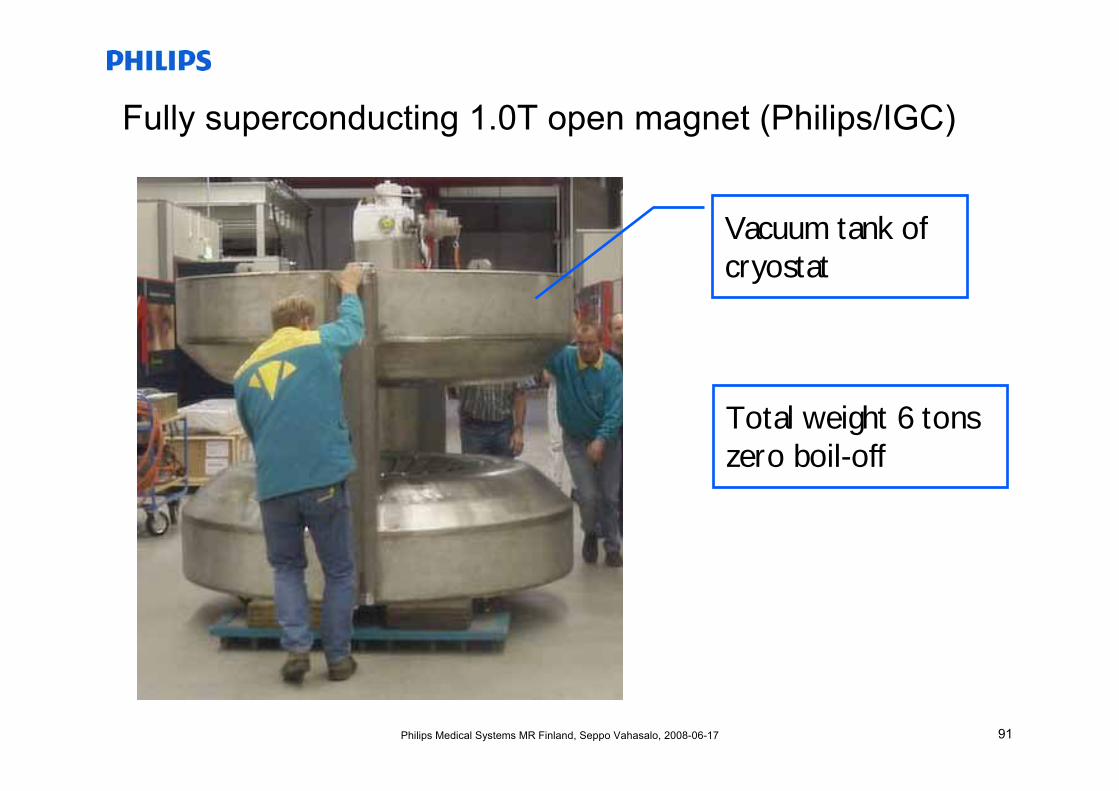
91Philips Medical Systems MR Finland, Seppo Vahasalo, 2008-06-17
Fully superconducting 1.0T open magnet (Philips/IGC)
Vacuum tank ofcryostat
Total weight 6 tonszero boil-off
92Philips Medical Systems MR Finland, Seppo Vahasalo, 2008-06-17
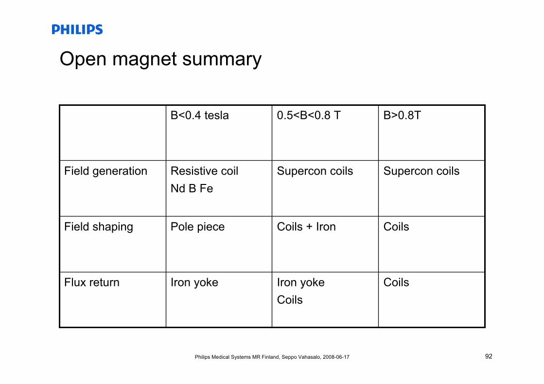
Open magnet summary
CoilsIron yokeCoils
Iron yokeFlux return
CoilsCoils + IronPole pieceField shaping
Supercon coilsSupercon coilsResistive coilNd B Fe
Field generation
B>0.8T0.5<B<0.8 TB<0.4 tesla
93Philips Medical Systems MR Finland, Seppo Vahasalo, 2008-06-17
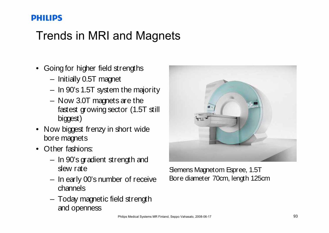
Trends in MRI and Magnets
• Going for higher field strengths– Initially 0.5T magnet– In 90’s 1.5T system the majority– Now 3.0T magnets are the
fastest growing sector (1.5T still biggest)
• Now biggest frenzy in short wide bore magnets
• Other fashions:– In 90’s gradient strength and
slew rate– In early 00’s number of receive
channels– Today magnetic field strength
and openness
Siemens Magnetom Espree, 1.5TBore diameter 70cm, length 125cm
94Philips Medical Systems MR Finland, Seppo Vahasalo, 2008-06-17
MRI Markets and players
• Price about 750 – 2000 k€/system
• About 3000 systems sold annually
– Biggest market share: Siemens
– Traditional number one, GE has been trailing, now about the same with Philips
– All the rest (Hitachi, Toshiba, etc) fairly small
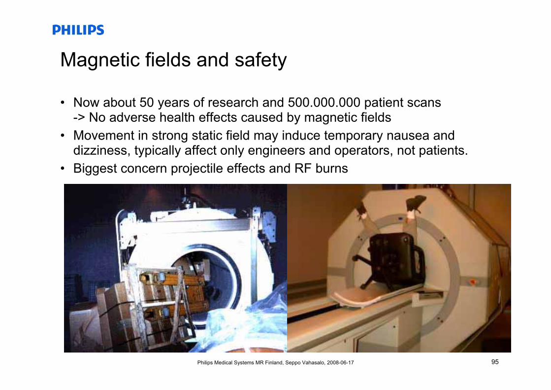
95Philips Medical Systems MR Finland, Seppo Vahasalo, 2008-06-17
Magnetic fields and safety
• Now about 50 years of research and 500.000.000 patient scans-> No adverse health effects caused by magnetic fields
• Movement in strong static field may induce temporary nausea and dizziness, typically affect only engineers and operators, not patients.
• Biggest concern projectile effects and RF burns
96Philips Medical Systems MR Finland, Seppo Vahasalo, 2008-06-17
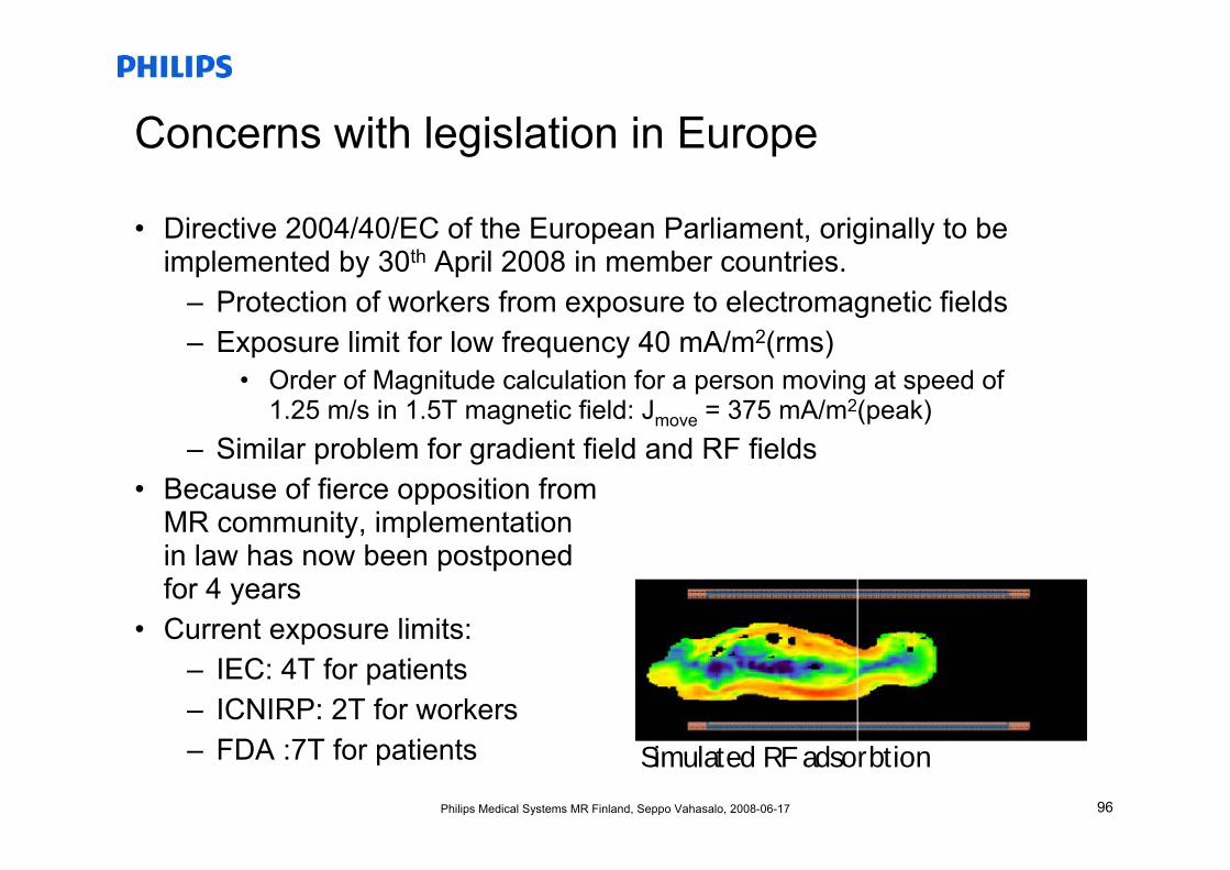
Concerns with legislation in Europe
• Directive 2004/40/EC of the European Parliament, originally to be implemented by 30th April 2008 in member countries.
– Protection of workers from exposure to electromagnetic fields– Exposure limit for low frequency 40 mA/m2(rms)
• Order of Magnitude calculation for a person moving at speed of 1.25 m/s in 1.5T magnetic field: Jmove = 375 mA/m2(peak)
– Similar problem for gradient field and RF fields• Because of fierce opposition from
MR community, implementationin law has now been postponedfor 4 years
• Current exposure limits:– IEC: 4T for patients– ICNIRP: 2T for workers– FDA :7T for patients Simulated RF adsorbtion
97Philips Medical Systems MR Finland, Seppo Vahasalo, 2008-06-17
Thanks
Thanks toJ. Overweg and M. Savelainen
for simulation/magnet pictures and magnet information
Thank you for your attention
Questions?