Neutron absorption cross-sections of important nuclideschem2/NuclearEnergySlides 4-28-09.pdf ·...
31
Nuclide σ (barns) neutron absorption Comments 4 2 He ∼ 0 gas cooled reactor coolant, “fi lled shell”, nucleus is an alpha particle 16 8 O 0. 00019 in light & heavy water, “fi lled shell”, is like 4 alphas 2 1 H 0. 00052 deuterium, in D 2 O, good collisional energy transfer with modest absorption 12 6 C 0. 0035 graphite, good collisional transfer with modest absorption, “3 alphas” Zr 0. 18 zirconium, non-corrosive, high temp metal used for cladding fuel 1 1 H 0. 332 hydrogen, in H 2 O, optimum collisional energy transfer, medium absorption 238 92 U 2. 7 99.7% of natural uranium, low fission cross-section, A is even 115 49 In 3 × 10 4 at 1.46 eV resonance peak 235 92 U 681 0.7% of natural uranium, fission cross-section is similar 239 94 Pu 1022 fission cross-section is 750 barns 10 5 B 3840 boron, graphite contaminant, boronated water used for control 135 54 Xe 2. 6 × 10 6 fission product, “poison”, can cause restart problems (slow creation) 113 Cd 7800 at 0.175 eV resonance peak, used in control rods Neutron absorption cross-sections of important nuclides
Transcript of Neutron absorption cross-sections of important nuclideschem2/NuclearEnergySlides 4-28-09.pdf ·...

Nuclideσ(barns)neutronabsorption
Comments
42He ∼ 0 gas cooled reactor coolant, “filled shell”, nucleus is an alpha particle
168 O 0.00019 in light & heavy water, “filled shell”, is like 4 alphas
21H 0.00052 deuterium, in D2O, good collisional energy transfer with modest absorption
126 C 0.0035 graphite, good collisional transfer with modest absorption, “3 alphas”
Zr 0.18 zirconium, non-corrosive, high temp metal used for cladding fuel
11H 0.332 hydrogen, in H2O, optimum collisional energy transfer, medium absorption
23892 U 2.7 99.7% of natural uranium, low fission cross-section, A is even
11549 In 3 × 10⁴ at 1.46 eV resonance peak
23592 U 681 0.7% of natural uranium, fission cross-section is similar
23994 Pu 1022 fission cross-section is 750 barns
105 B 3840 boron, graphite contaminant, boronated water used for control
13554 Xe 2.6 × 10⁶ fission product, “poison”, can cause restart problems (slow creation)
113Cd 7800 at 0.175 eV resonance peak, used in control rods
Neutron absorption cross-sections of important nuclides
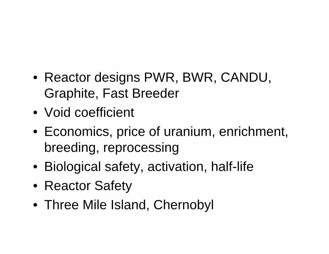
• Reactor designs PWR, BWR, CANDU, Graphite, Fast Breeder
• Void coefficient• Economics, price of uranium, enrichment,
breeding, reprocessing• Biological safety, activation, half-life• Reactor Safety• Three Mile Island, Chernobyl
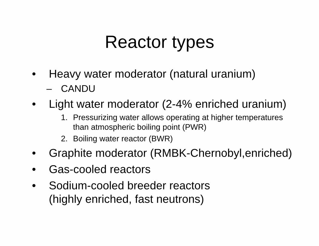
Reactor types
• Heavy water moderator (natural uranium)– CANDU
• Light water moderator (2-4% enriched uranium) 1. Pressurizing water allows operating at higher temperatures
than atmospheric boiling point (PWR)2. Boiling water reactor (BWR)
• Graphite moderator (RMBK-Chernobyl,enriched)• Gas-cooled reactors• Sodium-cooled breeder reactors
(highly enriched, fast neutrons)
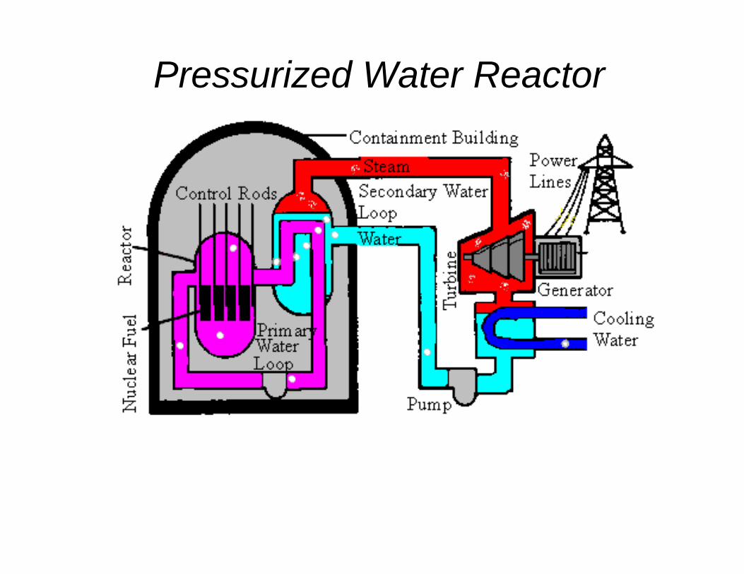
Pressurized Water Reactor
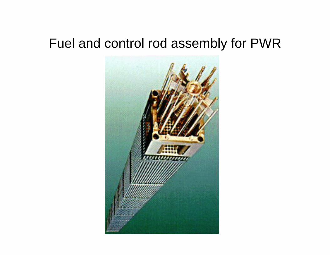
Fuel and control rod assembly for PWR
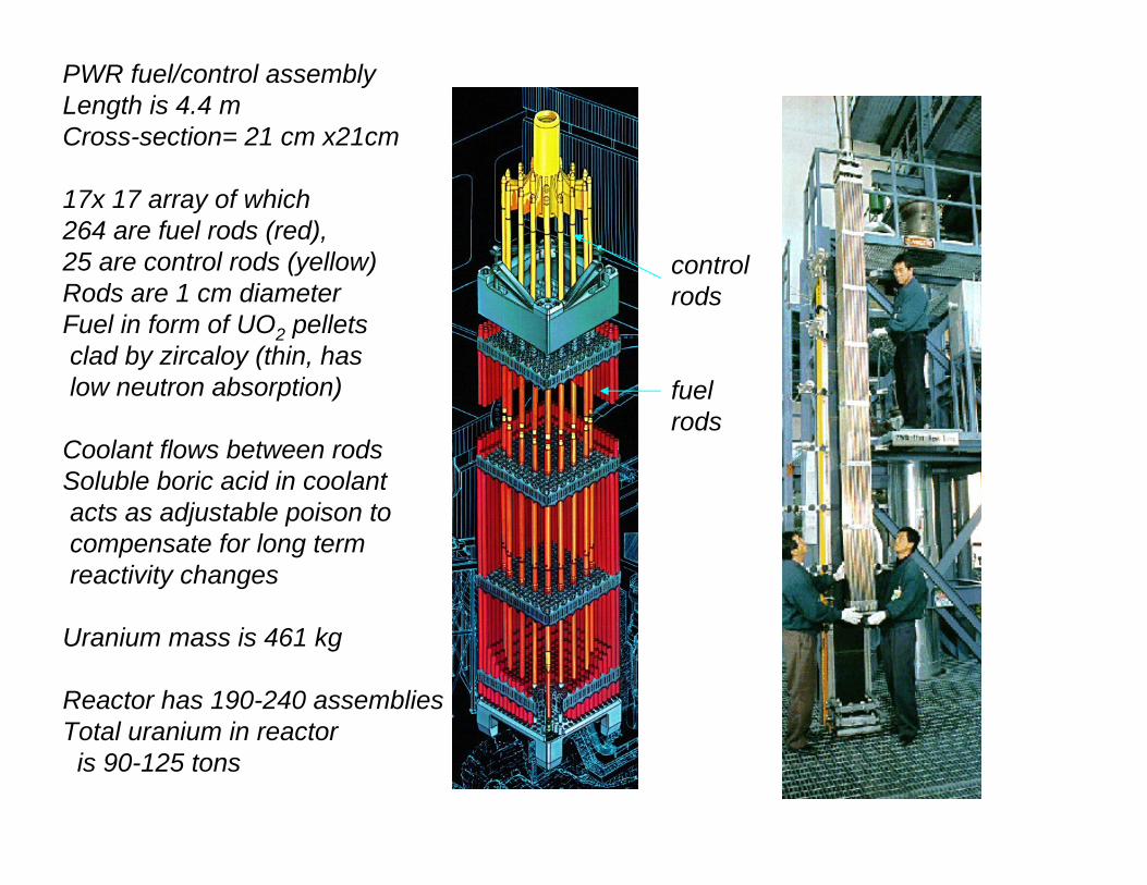
PWR fuel/control assemblyLength is 4.4 mCross-section= 21 cm x21cm
17x 17 array of which264 are fuel rods (red), 25 are control rods (yellow)Rods are 1 cm diameterFuel in form of UO2 pellets clad by zircaloy (thin, haslow neutron absorption)
Coolant flows between rodsSoluble boric acid in coolantacts as adjustable poison tocompensate for long termreactivity changes
Uranium mass is 461 kg
Reactor has 190-240 assembliesTotal uranium in reactoris 90-125 tons
controlrods
fuelrods
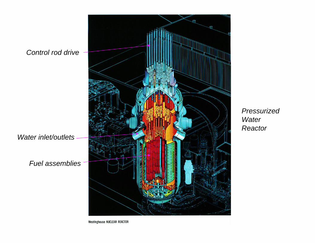
PressurizedWaterReactor
Fuel assemblies
Control rod drive
Water inlet/outlets
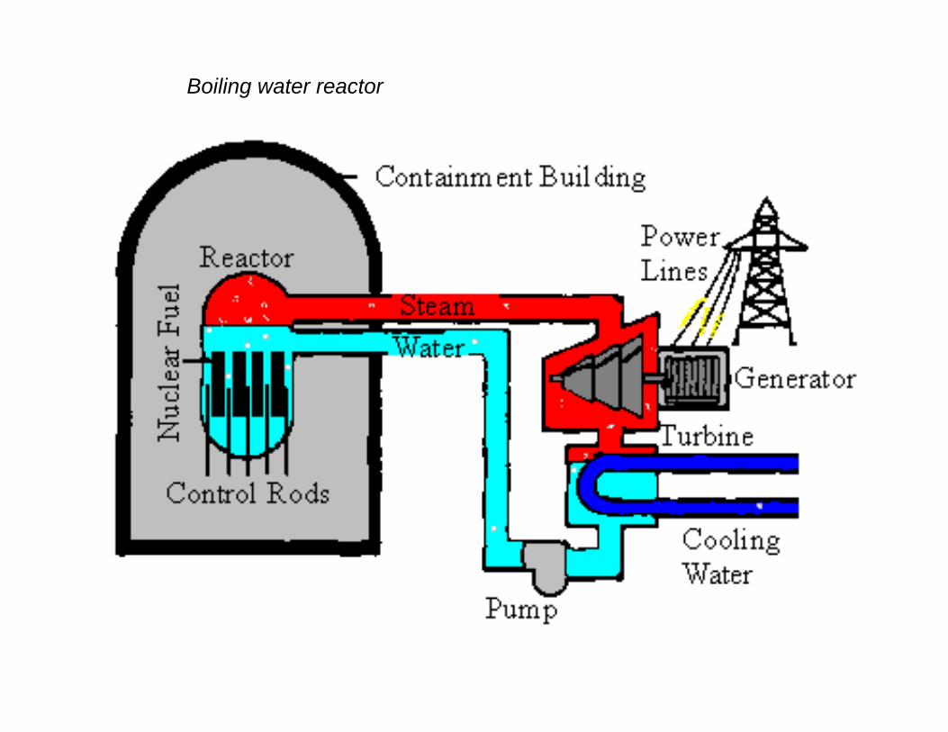
Boiling water reactor
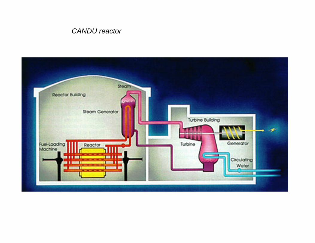
CANDU reactor
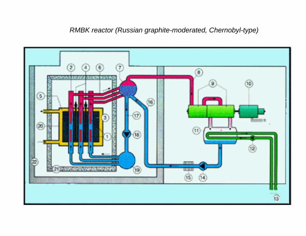
RMBK reactor (Russian graphite-moderated, Chernobyl-type)
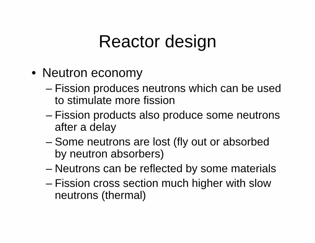
Reactor design
• Neutron economy– Fission produces neutrons which can be used
to stimulate more fission– Fission products also produce some neutrons
after a delay– Some neutrons are lost (fly out or absorbed
by neutron absorbers)– Neutrons can be reflected by some materials– Fission cross section much higher with slow
neutrons (thermal)
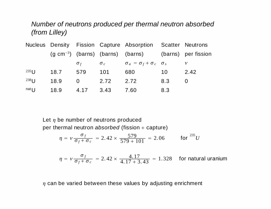
Number of neutrons produced per thermal neutron absorbed(from Lilley)
Nucleus Density Fission Capture Absorption Scatter Neutrons(g cm−3) (barns) (barns) (barns) (barns) per fission
f c a f c s
235U 18.7 579 101 680 10 2.42238U 18.9 0 2.72 2.72 8.3 0natU 18.9 4.17 3.43 7.60 8.3
Let be number of neutrons producedper thermal neutron absorbed (fission capture)
ff c
2. 42 579579 101 2.06 for 235U
ff c
2. 42 4.174.17 3. 43 1.328 for natural uranium
can be varied between these values by adjusting enrichment

Loss of neutrons due to capture
• Fast neutrons produced by fission must be slowed down to be thermal
• During this process, some neutrons will be captured by 238U
• Probability that neutrons are not captured is denoted by p
Thermal utilization factor
• Not all thermal neutrons are absorbed by fuel
• Some are absorbed by moderator and structure
• Let fraction absorbed by fuel be denoted by f
Leakage
• Let lf denote fraction of fast neutrons which leak out (i.e., before moderation)
• Let ls denote fraction of slow neutrons which leak out (i.e., after moderation)
• These provide another multiplier(1-lf)(1-ls)
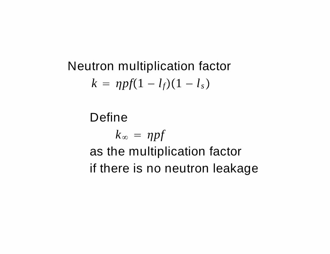
Neutron multiplication factork pf 1 − l f 1 − ls
Definek pf
as the multiplication factorif there is no neutron leakage
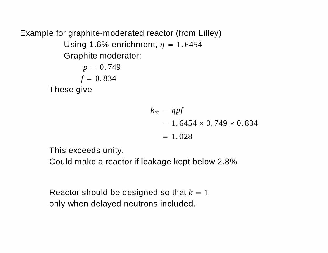
Example for graphite-moderated reactor (from Lilley)Using 1.6% enrichment, 1. 6454Graphite moderator:
p 0. 749f 0. 834
These give
k pf1. 6454 0. 749 0. 8341. 028
This exceeds unity.Could make a reactor if leakage kept below 2.8%
Reactor should be designed so that k 1only when delayed neutrons included.
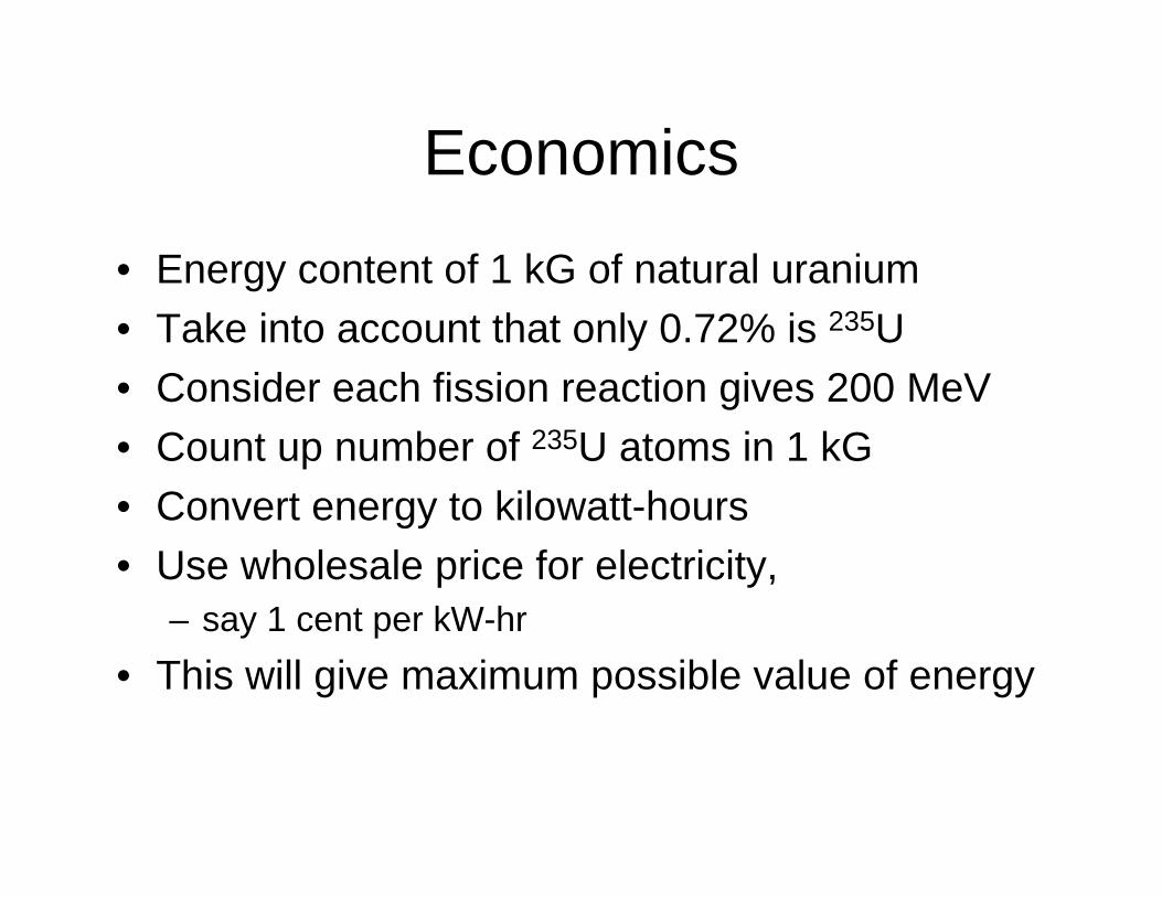
Economics
• Energy content of 1 kG of natural uranium• Take into account that only 0.72% is 235U• Consider each fission reaction gives 200 MeV• Count up number of 235U atoms in 1 kG• Convert energy to kilowatt-hours• Use wholesale price for electricity,
– say 1 cent per kW-hr• This will give maximum possible value of energy
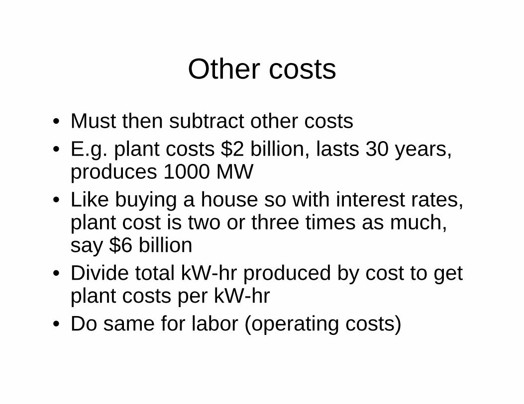
Other costs
• Must then subtract other costs• E.g. plant costs $2 billion, lasts 30 years,
produces 1000 MW• Like buying a house so with interest rates,
plant cost is two or three times as much, say $6 billion
• Divide total kW-hr produced by cost to get plant costs per kW-hr
• Do same for labor (operating costs)
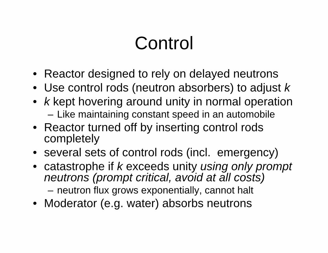
Control• Reactor designed to rely on delayed neutrons• Use control rods (neutron absorbers) to adjust k • k kept hovering around unity in normal operation
– Like maintaining constant speed in an automobile• Reactor turned off by inserting control rods
completely• several sets of control rods (incl. emergency)• catastrophe if k exceeds unity using only prompt
neutrons (prompt critical, avoid at all costs)– neutron flux grows exponentially, cannot halt
• Moderator (e.g. water) absorbs neutrons
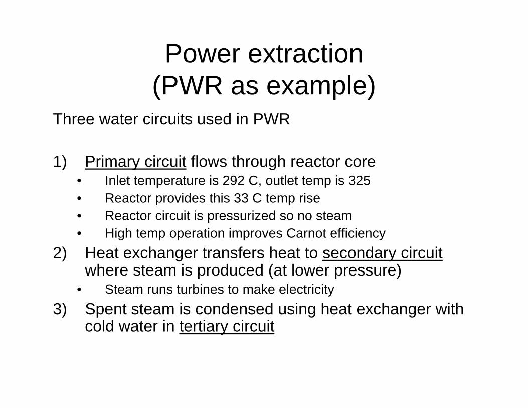
Power extraction (PWR as example)
Three water circuits used in PWR
1) Primary circuit flows through reactor core• Inlet temperature is 292 C, outlet temp is 325 • Reactor provides this 33 C temp rise• Reactor circuit is pressurized so no steam• High temp operation improves Carnot efficiency
2) Heat exchanger transfers heat to secondary circuitwhere steam is produced (at lower pressure)
• Steam runs turbines to make electricity3) Spent steam is condensed using heat exchanger with
cold water in tertiary circuit
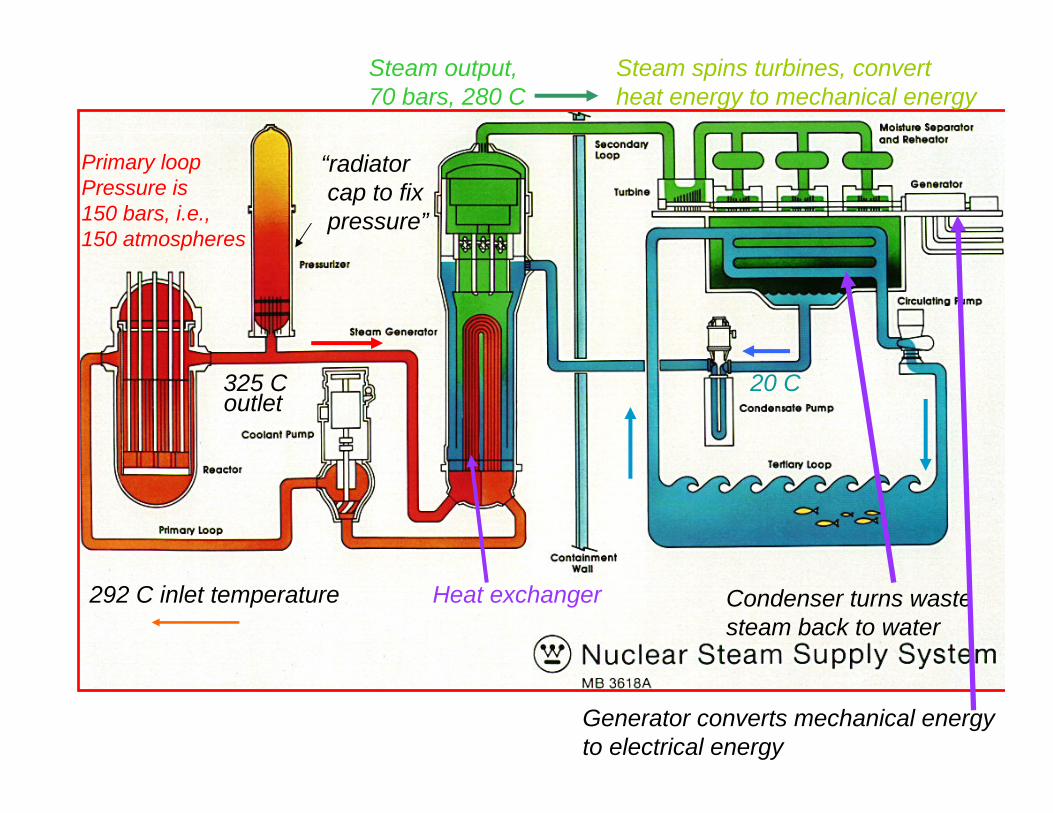
292 C inlet temperature
325 Coutlet
Heat exchanger
“radiatorcap to fixpressure”
Steam output, 70 bars, 280 C
Steam spins turbines, convert heat energy to mechanical energy
Condenser turns wastesteam back to water
Generator converts mechanical energyto electrical energy
Primary loopPressure is150 bars, i.e., 150 atmospheres
20 C
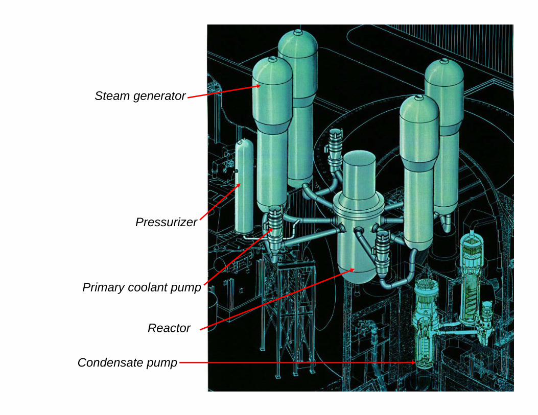
Reactor
Steam generator
Primary coolant pump
Pressurizer
Condensate pump
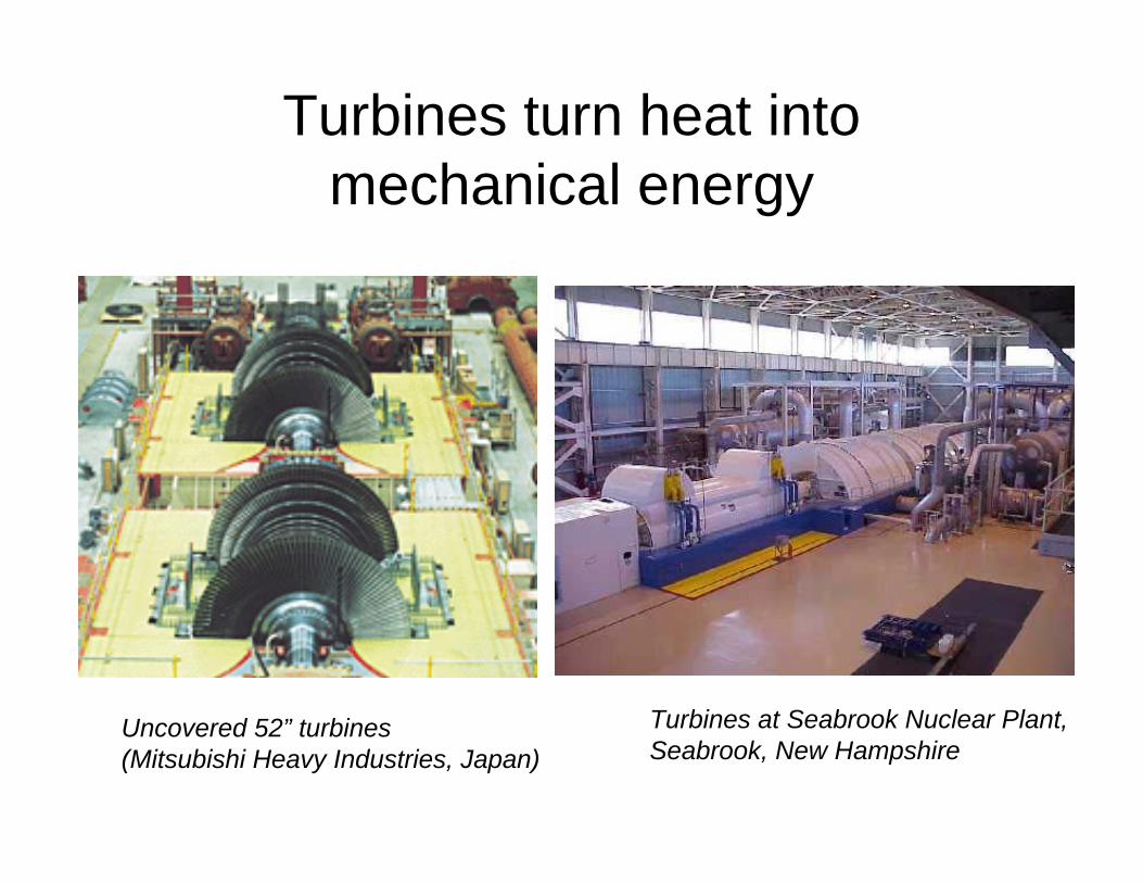
Turbines turn heat into mechanical energy
Uncovered 52” turbines(Mitsubishi Heavy Industries, Japan)
Turbines at Seabrook Nuclear Plant,Seabrook, New Hampshire
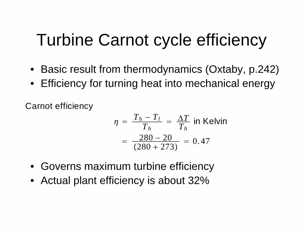
Turbine Carnot cycle efficiency• Basic result from thermodynamics (Oxtaby, p.242)• Efficiency for turning heat into mechanical energy
• Governs maximum turbine efficiency• Actual plant efficiency is about 32%
Carnot efficiencyTh − Tl
ThΔTTh
in Kelvin
280 − 20280 273 0. 47
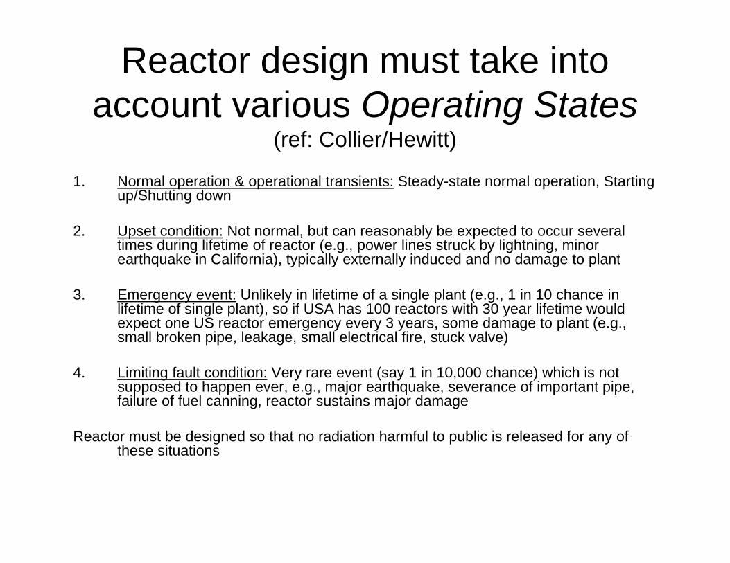
Reactor design must take into account various Operating States
(ref: Collier/Hewitt)
1. Normal operation & operational transients: Steady-state normal operation, Starting up/Shutting down
2. Upset condition: Not normal, but can reasonably be expected to occur several times during lifetime of reactor (e.g., power lines struck by lightning, minor earthquake in California), typically externally induced and no damage to plant
3. Emergency event: Unlikely in lifetime of a single plant (e.g., 1 in 10 chance inlifetime of single plant), so if USA has 100 reactors with 30 year lifetime would expect one US reactor emergency every 3 years, some damage to plant (e.g., small broken pipe, leakage, small electrical fire, stuck valve)
4. Limiting fault condition: Very rare event (say 1 in 10,000 chance) which is not supposed to happen ever, e.g., major earthquake, severance of important pipe, failure of fuel canning, reactor sustains major damage
Reactor must be designed so that no radiation harmful to public is released for any of these situations
PWR potential accident analysis
• System is designed to transfer substantial energy from reactor to load
• Typical thermal output in normal operation is 3400 MW
• When reactor turned off there is still 200 MW thermal produced by fission products
• If heat is not removed, this 200 MW overheats fuel rods
Fuel rod heat output
• Single fuel rod generates about 40 kW per meter in normal operation
• Generates about 2 kW per meter after shutdown due to decay of fission products
• In normal operation, primary water circuit removes this heat
• Need to maintain some flow after shutdown to remove 2 kW/meter
Consequences of fuel rod overheating
If heat not removed on shutdown, then get overheating– Loss of system pressurization causes steam to be produced
(like automobile radiator boiling over when pressure cap removed)– At ~800 C Zircaloy cladding swells, can block cooling channels– At ~1400 C Zircaloy breaks, fission products no longer clad, mix
with water – At ~1400 C steam interacts with Zircaloy to make H2– At 2700 C fuel melts
• With no cooling, fuel melting occurs in ~ 8 minutes• Thus, essential to maintain cooling
– Hence, many redundant systems to avoid loss of cooling• Accidents can interrupt coolant flow (leaks, pump failure)
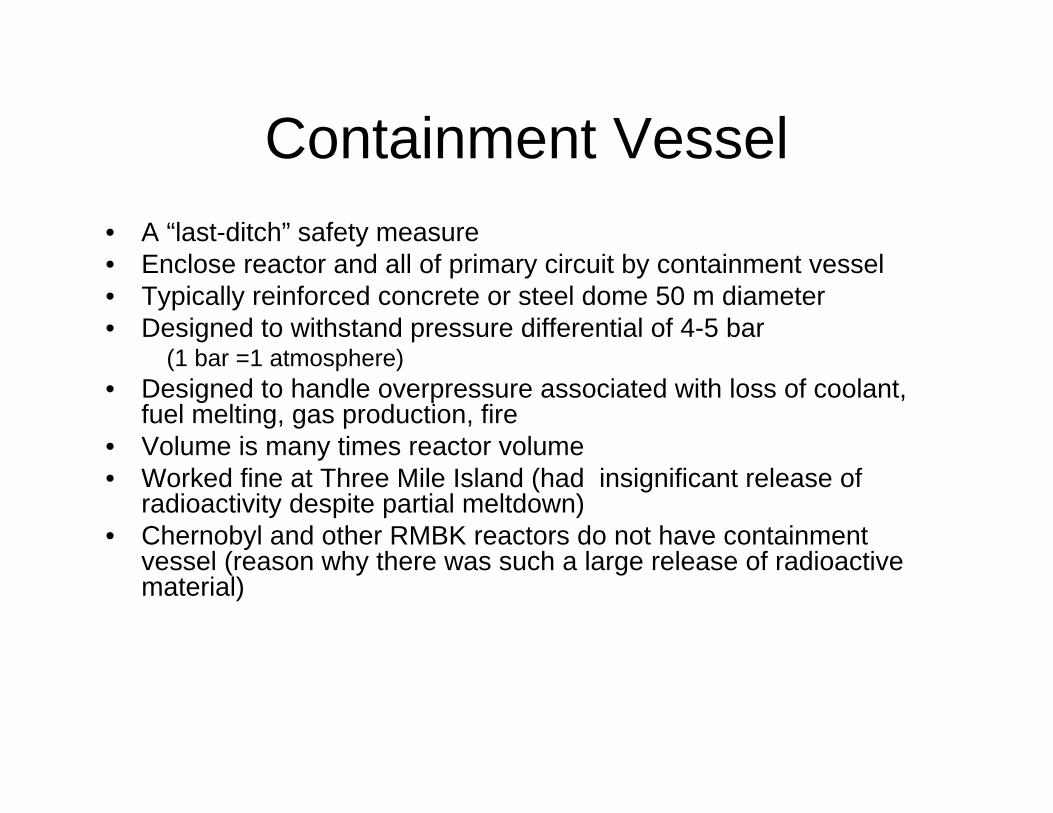
Containment Vessel• A “last-ditch” safety measure • Enclose reactor and all of primary circuit by containment vessel• Typically reinforced concrete or steel dome 50 m diameter• Designed to withstand pressure differential of 4-5 bar
(1 bar =1 atmosphere)• Designed to handle overpressure associated with loss of coolant,
fuel melting, gas production, fire• Volume is many times reactor volume• Worked fine at Three Mile Island (had insignificant release of
radioactivity despite partial meltdown)• Chernobyl and other RMBK reactors do not have containment
vessel (reason why there was such a large release of radioactivematerial)
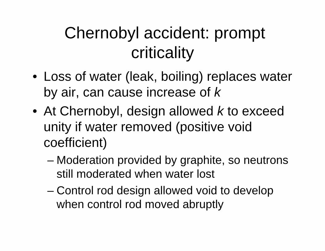
Chernobyl accident: prompt criticality
• Loss of water (leak, boiling) replaces water by air, can cause increase of k
• At Chernobyl, design allowed k to exceed unity if water removed (positive void coefficient)– Moderation provided by graphite, so neutrons
still moderated when water lost– Control rod design allowed void to develop
when control rod moved abruptly