Model 750 Control Moment Gyroscope Motors Servo Fact … · The CMG system is furnished with a...
2
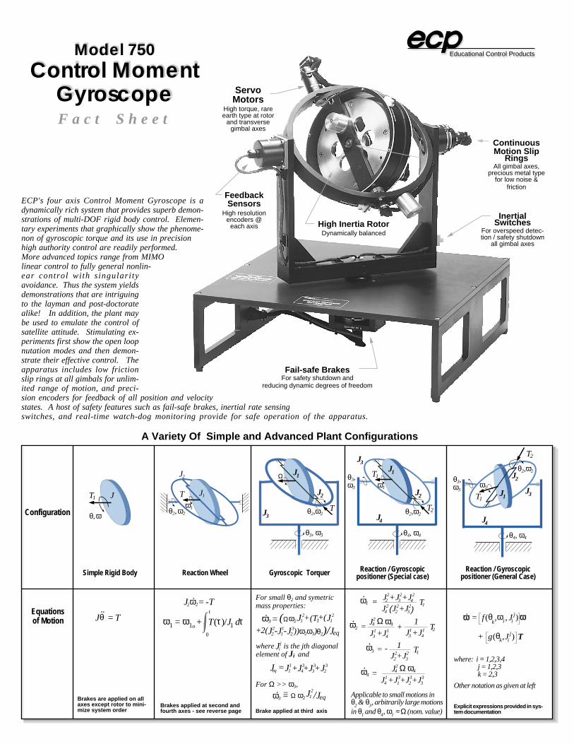
θ 3 , ϖ 3 J 3 J 4 T 2 θ 2 , ϖ 2 θ 4 , ϖ 4 J 1 J 2 T 1 ϖ 1 Fact Sheet Educational Control Products A Variety Of Simple and Advanced Plant Configurations Simple Rigid Body Reaction Wheel Gyroscopic Torquer Reaction / Gyroscopic positioner (Special case) Reaction / Gyroscopic positioner (General Case) θ, ϖ J θ 2 , ϖ 2 J 1 J 2 ϖ 1 T J 3 T θ 2 , ϖ 2 θ 3 , ϖ 3 J 1 J 2 Ω θ 3 , ϖ 3 J 4 T 2 θ 2 , ϖ 2 θ 4 , ϖ 4 J 1 J 2 ϖ 1 T 1 Configuration Equations of Motion J θ = T J 2 = -T T 1 ϖ 1 = ϖ 1o + T(τ )/J 1 d τ 0 t J 1 2 (Ωϖ 2 + (T 1 + J 1 2 ( ϖ 3 = θ 2 )/J eq J 2 2 J 1 1 J 2 3 -- ))ϖ 2 ϖ 3 ) +2( For small θ 2 and symetric mass properties: For Ω >> ϖ 3 , J 1 2 Ω ϖ 2 /J eq = ϖ 3 where is the jth diagonal element of J i and J i j J eq = J 1 1 J 4 3 J 3 3 J 2 3 + + + ϖ 1 = J 2 2 +J 3 2 +J 2 4 J 4 2 2 2 J +J 3 2 T 1 ( ) ϖ 2 = J 4 2 Ω J 3 1 +J 4 1 + T 2 ϖ 4 1 J 3 1 +J 4 1 ϖ 4 = J 4 2 Ω J 4 1 +J 1 3 ϖ 4 +J 2 3 +J 3 3 3 ϖ = 2 2 J +J 3 2 T 1 - 1 Applicable to small motions in θ 2 & θ 3 , arbitrarily large motions in θ 1 and θ 4 , ϖ 1 ≈ Ω (nom. value) ϖ = f (θ k ,ϖ i , J i j ϖ + g (θ k , J i j T ) ) where: i = 1,2,3,4 j = 1,2,3 k = 2,3 Other notation as given at left ϖ 2 Brakes are applied on all axes except rotor to mini- mize system order Brakes applied at second and fourth axes - see reverse page Brake applied at third axis Explicit expressions provided in sys- tem documentation High Inertia Rotor Dynamically balanced Servo Motors High torque, rare earth type at rotor and transverse gimbal axes Continuous Motion Slip Rings All gimbal axes, precious metal type for low noise & friction Feedback Sensors High resolution encoders @ each axis Model 750 Control Moment Gyroscope ECP's four axis Control Moment Gyroscope is a dynamically rich system that provides superb demon- strations of multi-DOF rigid body control. Elemen- tary experiments that graphically show the phenome- non of gyroscopic torque and its use in precision high authority control are readily performed. More advanced topics range from MIMO linear control to fully general nonlin- ear control with singularity avoidance. Thus the system yields demonstrations that are intriguing to the layman and post-doctorate alike! In addition, the plant may be used to emulate the control of satellite attitude. Stimulating ex- periments first show the open loop nutation modes and then demon- strate their effective control. The apparatus includes low friction slip rings at all gimbals for unlim- ited range of motion, and preci- sion encoders for feedback of all position and velocity states. A host of safety features such as fail-safe brakes, inertial rate sensing switches, and real-time watch-dog monitoring provide for safe operation of the apparatus. Fail-safe Brakes For safety shutdown and reducing dynamic degrees of freedom Inertial Switches For overspeed detec- tion / safety shutdown all gimbal axes J 3 ~
Transcript of Model 750 Control Moment Gyroscope Motors Servo Fact … · The CMG system is furnished with a...
θ3,ω3 J3
J4
T2
θ2, ω2
θ4, ω4
J1
J2
T1
ω1
F a c t S h e e t
Educational Control Products
A Variety Of Simple and Advanced Plant Configurations
Simple Rigid Body Reaction Wheel Gyroscopic Torquer Reaction / Gyroscopicpositioner (Special case)
Reaction / Gyroscopicpositioner (General Case)
θ, ω
J
θ2, ω2
J1
J2
ω1
T
J3Tθ2, ω2
θ3, ω3
J1
J2
Ω θ3,ω3
J4
T2θ2, ω2
θ4, ω4
J1
J2
ω1
T1
Configuration
Equationsof Motion Jθ = T
J2 = -T
T1
ω1 = ω1o + T(τ )/J1 dτ0
tJ1
2(Ω ω2 +(T1+ J12(ω3 =
θ2)/JeqJ22 J1
1 J23- - ))ω2ω3)+2(
For small θ2 and symetricmass properties:
For Ω >> ω3, J1
2Ω ω2 /Jeq =ω3
where is the jth diagonalelement of Ji and
Jij
Jeq =J11 J4
3 J33 J2
3+ + +
ω1 = J2
2+J32+J2
4
J42
22J +J3
2 T1( )
ω2 =
J42 Ω
J31+J4
1 + T2
ω4 1J3
1+J41
ω4 =
J42 Ω
J41+J1
3
ω4
+J23+J3
3
3ω =22J +J3
2 T1- 1
Applicable to small motions inθ2 & θ3, arbitrarily large motionsin θ1 and θ4, ω1 ≈ Ω (nom. value)
ω = f (θk, ωi , Ji
j ω
+ g(θk,Jij T
)
)
where: i = 1,2,3,4j = 1,2,3k = 2,3
Other notation as given at left
ω2
Brakes are applied on allaxes except rotor to mini-mize system order
Brakes applied at second andfourth axes - see reverse page Brake applied at third axis
Explicit expressions provided in sys-tem documentation
High Inertia RotorDynamically balanced
ServoMotors
High torque, rareearth type at rotor
and transversegimbal axes
ContinuousMotion Slip
RingsAll gimbal axes,
precious metal typefor low noise &
frictionFeedbackSensors
High resolutionencoders @
each axis
Model 750Control Moment
Gyroscope
ECP's four axis Control Moment Gyroscope is adynamically rich system that provides superb demon-strations of multi-DOF rigid body control. Elemen-tary experiments that graphically show the phenome-non of gyroscopic torque and its use in precisionhigh authority control are readily performed.More advanced topics range from MIMOlinear control to fully general nonlin-ear control with singulari tyavoidance. Thus the system yieldsdemonstrations that are intriguingto the layman and post-doctoratealike! In addition, the plant maybe used to emulate the control ofsatellite attitude. Stimulating ex-periments first show the open loopnutation modes and then demon-strate their effective control. Theapparatus includes low frictionslip rings at all gimbals for unlim-ited range of motion, and preci-sion encoders for feedback of all position and velocitystates. A host of safety features such as fail-safe brakes, inertial rate sensingswitches, and real-time watch-dog monitoring provide for safe operation of the apparatus.
Fail-safe BrakesFor safety shutdown and
reducing dynamic degrees of freedom
InertialSwitches
For overspeed detec-tion / safety shutdown
all gimbal axes
J3
~
Quality Components Provide High System PerformanceTurn-key Systems* for Easy Setup & Operation
Thought-provoking Experiments
Contact us For More Information1-800-486-0840
Toll-free in the US & Canada
www.ecpsystems.com
The CMG system is furnished with a broad range of exper-iments that graphically demonstrate important theoreticalprinciples and applied control implementation. All exper-iments include detailed student procedures, supplementaryexercises, and complete instructor solutions. Also provid-ed are plant dynamic models, Matlab® scripts for analysisand simulation, and optional exercises to taylor yourcourse content.Initial tests demonstrate salient dynamic characteristicsand identify plant parameters. Experiments demonstratethe gyroscopic phenomena of the momentum/velocity crossproduct as well as precession, nutation, and conservationof angular momentum, Closed loop experiments beginwith basic rigid body control (see reverse page) to demon-strate fundamental principles. Reaction wheel experi-ments show the ramifications of providing control effortthrough a free-spinning base where practical issues of mo-tor torque/speed and saturation become essential designfactors for any such system. Gyroscopic torque control isstudied and seen to provide extremely high control author-ity through actuating the cross-axis gimbal. This achievesdramatic high bandwidth and precision control.MIMO experiments of the combined reaction and gyroscopiccontrol modes evaluate relative performance of various de-sign approaches and provide graphic demonstrations oflarge motion, complex system control. The system is thenconfigured in off-nominal gimbal orientations where cross-coupling between the control modes is strong and effectivemultivariable control design is implemented.The full nonlinear system model and many useful special cas-es are provided to support advanced research in areas ofsuch as gain scheduling, workspace/trajectory planning, andsingularity avoidance.
E-mail: Info@ ecpsystems.comPh: (818) 703-0802Fax: (818) 703-6040
Educational Control Products5725 Ostin Avenue
Woodland Hills, CA 91367* "Plant Only" option available without DSP board & I/F software
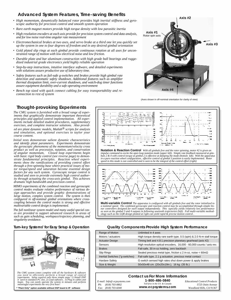
• High momentum, dynamically balanced rotor provides high inertial stiffness and gyro-scopic authority for precision control and smooth system operation
• Rare earth magnet motors provide high torque density with low parasitic inertia
• High resolution encoders at each axis provide for precision system control and data analysis,and for low noise real-time angular rate measurement
• Electromechanical brakes at two axes, and servo brake at a third one let you quickly setup the system in one to four degrees of freedom and in any desired gimbal orientation
• Gold plated slip rings at each gimbal provide continuous rotation at all axes for uncon-strained range of motion with low electrical noise and low friction.
• Durable plate and bar aluminum construction with high grade ball bearings and rugge-dized industrial grade electronics yield highly reliable operation
• Step-by-step instructions, intuitive interface software, and detailed experimentswith solutions assure productive use of laboratory time.
• Safety features such as fail-safe g-switches and brakes provide high gimbal ratedetection and automatic safety shutdown. Additional features such as amplifierthermal dissipation limit, over-current shutdown, and watch-dog timer functionsassure equipment durability and a safe operating environment
• Bench top sized with quick connect cabling for easy transportability and re-connection to rest of system
Advanced System Features, Time-saving Benefits
Nutation & Reaction Control With all gimbals free and the rotor spinning, motor #2 is given animpulse command to excite the open loop nutation mode (upper left). Simple rate feedback measured at gim-bals 2 & 4 with control torque at gimbal 2 is effective at damping the mode (bottom left). With the apparatusin a pure reaction wheel configuration, effective control of gimbal 3 position is easily implemented. Rotorspeed in this mode is not controlled and is seen to be the integral of the control effort (right)
Multi-variable Control The apparatus is configured with all gimbals free and the rotor initialized toa nominal speed. The combined gyroscopic and reaction control may be accomplished through simple lin-ear controllers designed for each output independently. This typically yields relatively low performanceas seen at the gimbal 3 and 4 outputs in following sawtooth trajectories (left). Full multi-variable method-ology such as the LQR design plotted at right can yield rapid & precise motion control .
Axis #2
Axis #1Rotor spin axis
Axis #3
Axis #4
(Axes shown in off-nominal orientation for clarity of view)
The CMG system comes complete with all the hardware & softwareyou need to efficiently perform a broad range of controlexperiments. Setup requires only three simple steps: 1) Install DSPb oard in standard PC slot, 2) Load software, 3) Plug in cables andbegin. You can easily operate the system in minutes and performmeaningful experiments the very first hour!
Range of Motion
Motors / actuators
Actuator Design
Sensors
Brakes
Slip Rings
Inertial Switches ("g-switches)
Hardare Safety
Size & Weight
Unlimited in 4 axes
High torque density rare earth type. 0.5 (spin) & 2.0 N-m stall torque
TIming belt and 4.8:1 precision planetary gearhead (axis #2)
High resolution optical encoders, 16,000 - 60,000 counts / axis rev.
Fail-safe, 30 in-oz holding, zero backlash
Sealed precious metal type, friction ≤ 2 in-oz, noise < 60mΩFail-safe type, 2.1 g actuation, precious metal contact
G-switch sensed high rates shut down power & apply brakes
50x50x48 cm. (20x20x19in.), 16 kg. (35 lb.)