Midterm 3 Review - Wake Forest Student, Faculty and Staff...
32
Midterm 3 Review
Transcript of Midterm 3 Review - Wake Forest Student, Faculty and Staff...
Midterm 3 Review
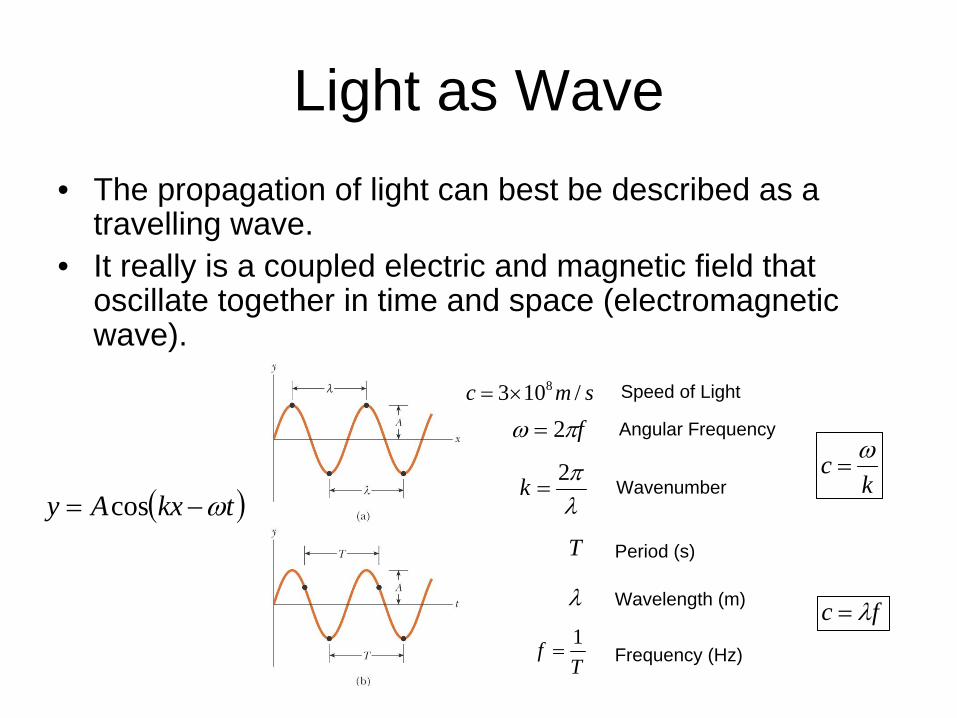
Light as Wave• The propagation of light can best be described as a
travelling wave.• It really is a coupled electric and magnetic field that
oscillate together in time and space (electromagnetic wave).
λπ2
=k Wavenumber
fπω 2= Angular Frequency
fc λ=
T Period (s)
λ Wavelength (m)
Frequency (Hz)Tf 1=
kc ω=
( )tkxAy ω−= cos
smc /103 8×= Speed of Light
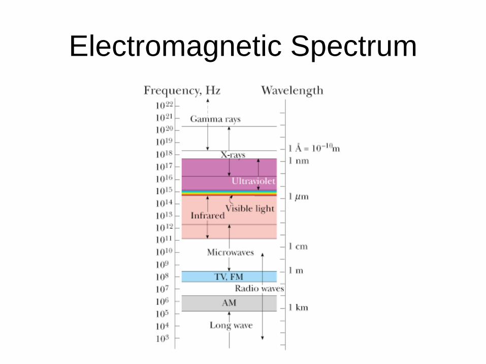
Electromagnetic Spectrum
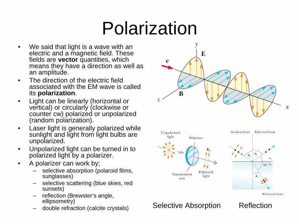
Polarization• We said that light is a wave with an
electric and a magnetic field. These fields are vector quantities, which means they have a direction as well as an amplitude.
• The direction of the electric field associated with the EM wave is called its polarization.
• Light can be linearly (horizontal or vertical) or circularly (clockwise or counter cw) polarized or unpolarized (random polarization).
• Laser light is generally polarized while sunlight and light from light bulbs are unpolarized.
• Unpolarized light can be turned in to polarized light by a polarizer.
• A polarizer can work by; – selective absorption (polaroid films,
sunglasses)– selective scattering (blue skies, red
sunsets)– reflection (Brewster’s angle,
ellipsometry)– double refraction (calcite crystals) Selective Absorption Reflection
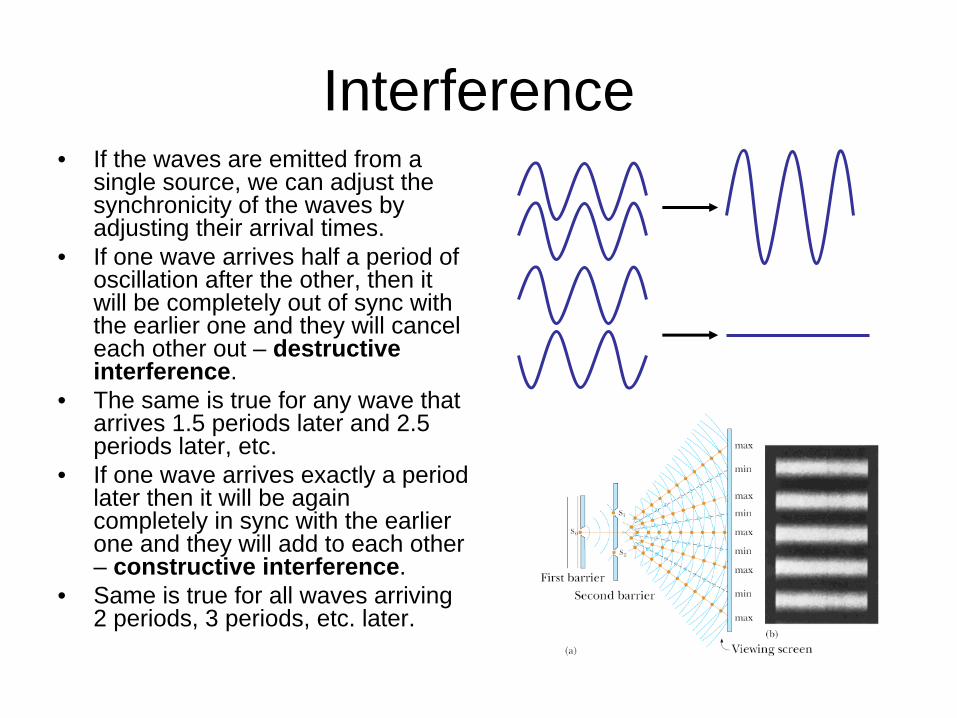
Interference• If the waves are emitted from a
single source, we can adjust the synchronicity of the waves by adjusting their arrival times.
• If one wave arrives half a period of oscillation after the other, then it will be completely out of sync with the earlier one and they will cancel each other out – destructive interference.
• The same is true for any wave that arrives 1.5 periods later and 2.5 periods later, etc.
• If one wave arrives exactly a period later then it will be again completely in sync with the earlier one and they will add to each other – constructive interference.
• Same is true for all waves arriving 2 periods, 3 periods, etc. later.
Thin Film Interference• Consider a thin film that is at least partially transparent to light.• If light is incident from the top, some of the light will be reflected
and some will be transmitted in to the film.• Similarly, as the transmitted light tries goes on to exit the film at the
bottom, there will be reflection and transmission.• The waves that were reflected from the top of the film and the
bottom of the film will interfere with each other.• If the delay introduced by the thickness of the film matches an
integer multiple of the period of light, there will be constructive interference.
• If it is half a period of delay, there will be destructive interference.• One additional wrinkle is that waves that reflect off of a higher
index medium will undergo a 180° phase change so that a delay of one period results in destructive interference and a delay of half a period results in constructive interference.
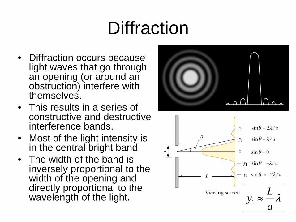
Diffraction• Diffraction occurs because
light waves that go through an opening (or around an obstruction) interfere with themselves.
• This results in a series of constructive and destructive interference bands.
• Most of the light intensity is in the central bright band.
• The width of the band is inversely proportional to the width of the opening and directly proportional to the wavelength of the light. λ
aLy ≈1
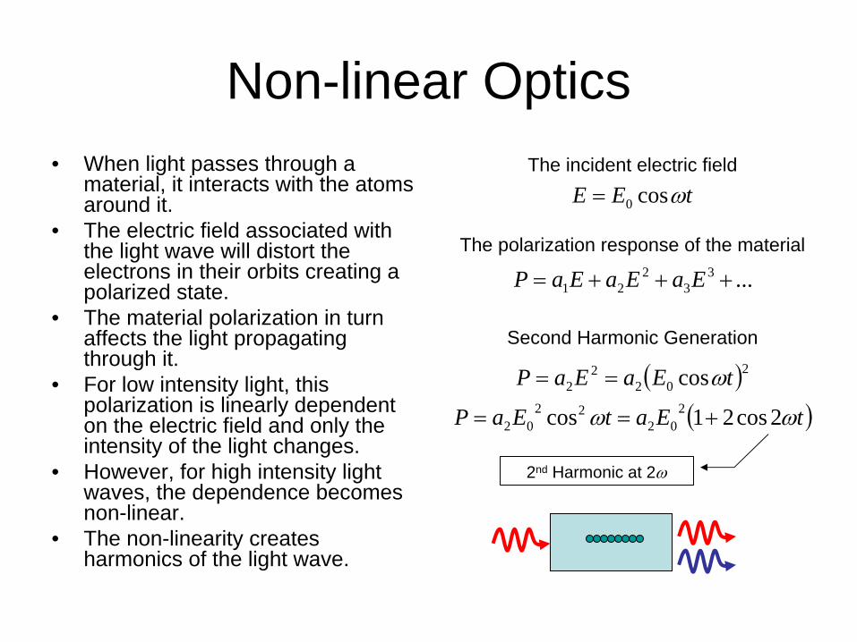
Non-linear Optics• When light passes through a
material, it interacts with the atoms around it.
• The electric field associated with the light wave will distort the electrons in their orbits creating a polarized state.
• The material polarization in turn affects the light propagating through it.
• For low intensity light, this polarization is linearly dependent on the electric field and only the intensity of the light changes.
• However, for high intensity light waves, the dependence becomes non-linear.
• The non-linearity creates harmonics of the light wave.
...33
221 +++= EaEaEaP
tEE ωcos0=
( )( )tEatEaP
tEaEaP
ωω
ω
2cos21cos
cos2
0222
02
202
22
+==
==
The incident electric field
The polarization response of the material
Second Harmonic Generation
2nd Harmonic at 2ω
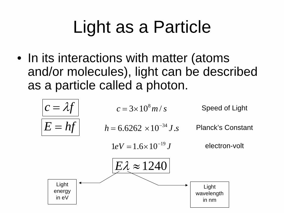
Light as a Particle
• In its interactions with matter (atoms and/or molecules), light can be described as a particle called a photon.
fc λ=hfE =
smc /103 8×= Speed of Light
sJh .10 6.6262 34−×= Planck’s Constant
JeV 19106.11 −×= electron-volt
1240≈λELight
energy in eV
Light wavelength
in nm
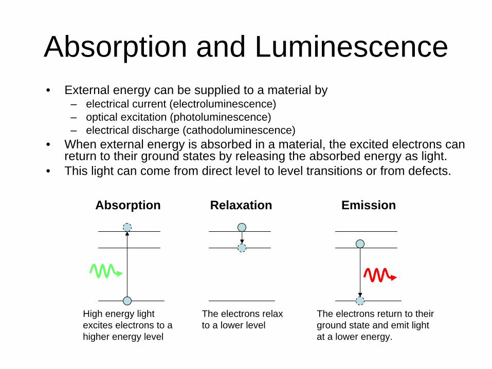
Absorption and Luminescence• External energy can be supplied to a material by
– electrical current (electroluminescence)– optical excitation (photoluminescence)– electrical discharge (cathodoluminescence)
• When external energy is absorbed in a material, the excited electrons can return to their ground states by releasing the absorbed energy as light.
• This light can come from direct level to level transitions or from defects.
High energy light excites electrons to a higher energy level
The electrons relax to a lower level
The electrons return to their ground state and emit light at a lower energy.
Absorption Relaxation Emission
Lattice Vibrations• Atoms making up a crystal lattice can vibrate or rotate in their place. • These oscillations can be thought of individual entities, called
phonons, that have a characteristic oscillation frequency and energy (E = hf).
• The energy of the vibration is dependent on the composition of the crystal and the chemical bonds.
• Lattice vibrations are also how sound waves propagate through materials.
• If the vibrations are in the direction of the lattice, they are called longitudinal vibrations.
• If they are in perpendicular to the direction of the lattice, they are transverse vibrations.
• Transverse vibration energies are in the order of tens of meV.
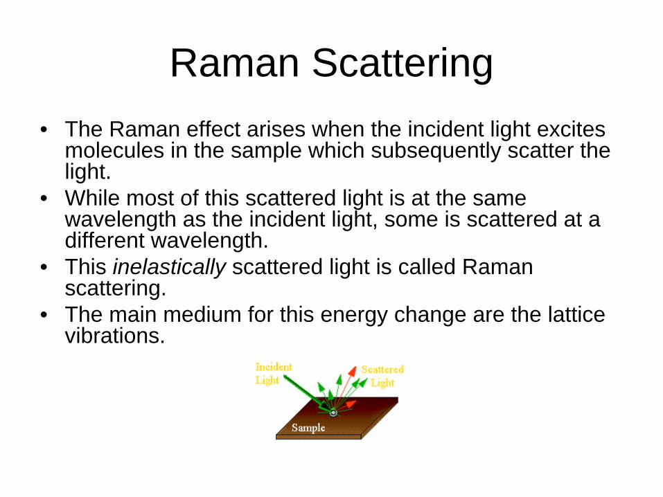
Raman Scattering• The Raman effect arises when the incident light excites
molecules in the sample which subsequently scatter the light.
• While most of this scattered light is at the same wavelength as the incident light, some is scattered at a different wavelength.
• This inelastically scattered light is called Raman scattering.
• The main medium for this energy change are the lattice vibrations.
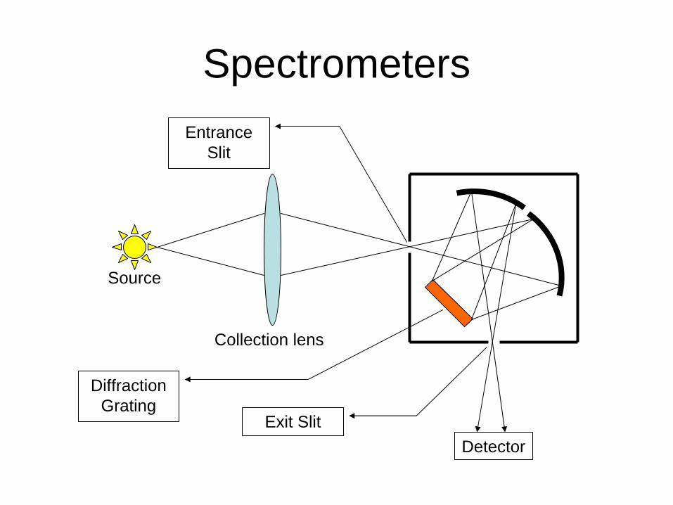
Spectrometers
Source
Collection lens
Entrance Slit
Exit Slit
Diffraction Grating
Detector
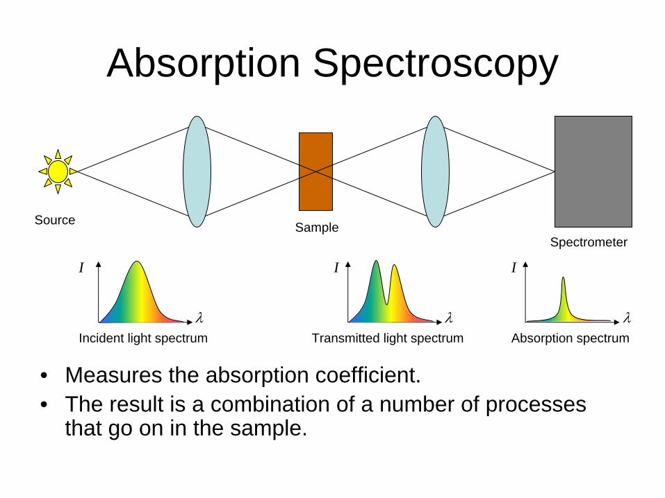
Absorption Spectroscopy
• Measures the absorption coefficient.• The result is a combination of a number of processes
that go on in the sample.
SampleSpectrometer
Incident light spectrum Transmitted light spectrum
Source
Absorption spectrum
I
λ
I
λ
I
λ
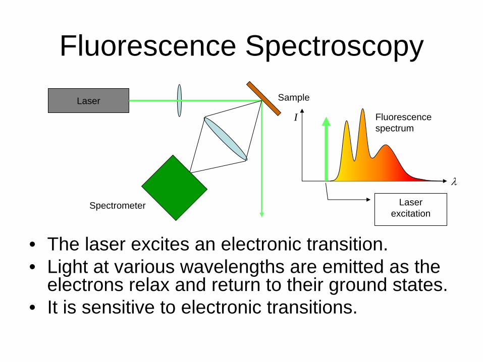
Fluorescence Spectroscopy
• The laser excites an electronic transition.• Light at various wavelengths are emitted as the
electrons relax and return to their ground states.• It is sensitive to electronic transitions.
Laser Sample
Spectrometer
Fluorescence spectrum
Laser excitation
I
λ
Excitation Spectroscopy
• Same setup but now change the excitation wavelength and detect at a single wavelength.
• Used for precision measurement of molecular absorption lines.
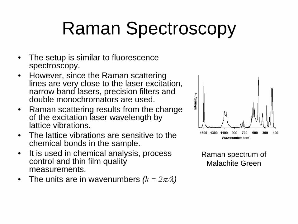
Raman Spectroscopy• The setup is similar to fluorescence
spectroscopy.• However, since the Raman scattering
lines are very close to the laser excitation, narrow band lasers, precision filters and double monochromators are used.
• Raman scattering results from the change of the excitation laser wavelength by lattice vibrations.
• The lattice vibrations are sensitive to the chemical bonds in the sample.
• It is used in chemical analysis, process control and thin film quality measurements.
• The units are in wavenumbers (k = 2π/λ)
Raman spectrum of Malachite Green
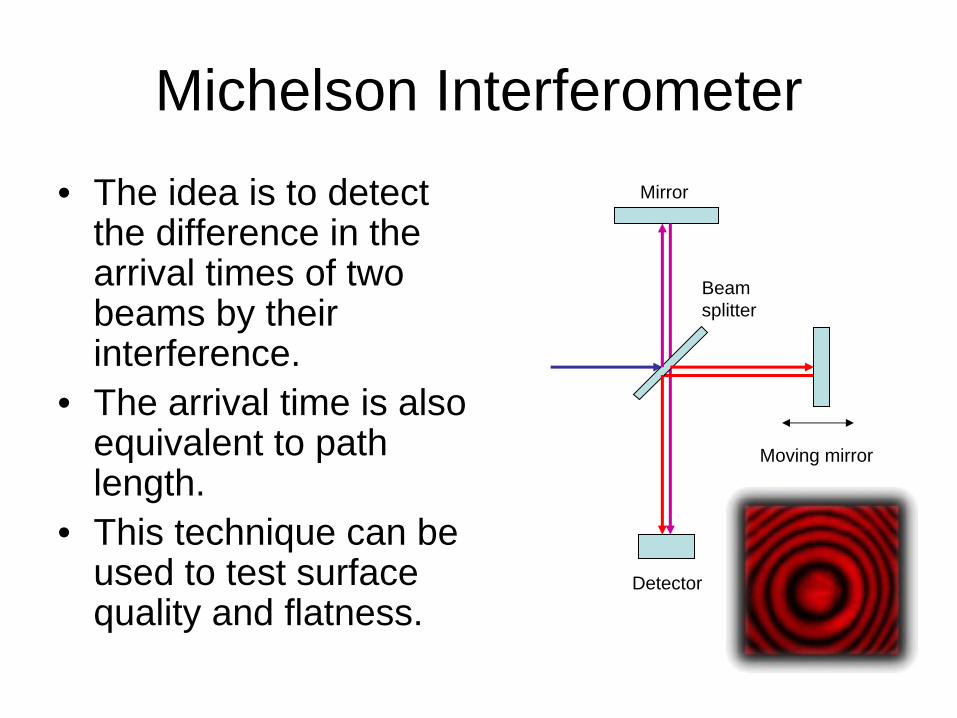
Michelson Interferometer• The idea is to detect
the difference in the arrival times of two beams by their interference.
• The arrival time is also equivalent to path length.
• This technique can be used to test surface quality and flatness.
Mirror
Moving mirror
Detector
Beam splitter
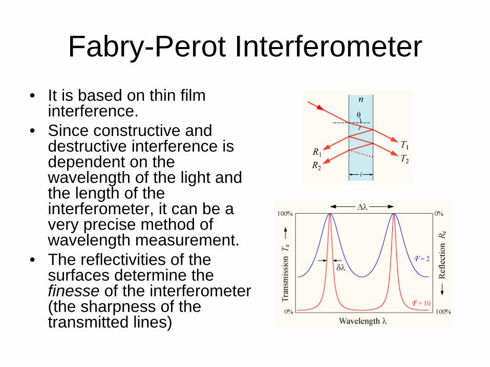
Fabry-Perot Interferometer• It is based on thin film
interference.• Since constructive and
destructive interference is dependent on the wavelength of the light and the length of the interferometer, it can be a very precise method of wavelength measurement.
• The reflectivities of the surfaces determine the finesse of the interferometer (the sharpness of the transmitted lines)
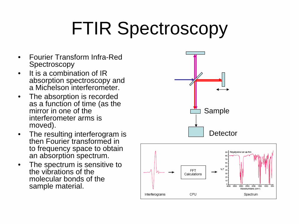
FTIR Spectroscopy• Fourier Transform Infra-Red
Spectroscopy• It is a combination of IR
absorption spectroscopy and a Michelson interferometer.
• The absorption is recorded as a function of time (as the mirror in one of the interferometer arms is moved).
• The resulting interferogram is then Fourier transformed in to frequency space to obtain an absorption spectrum.
• The spectrum is sensitive to the vibrations of the molecular bonds of the sample material.
Sample
Detector
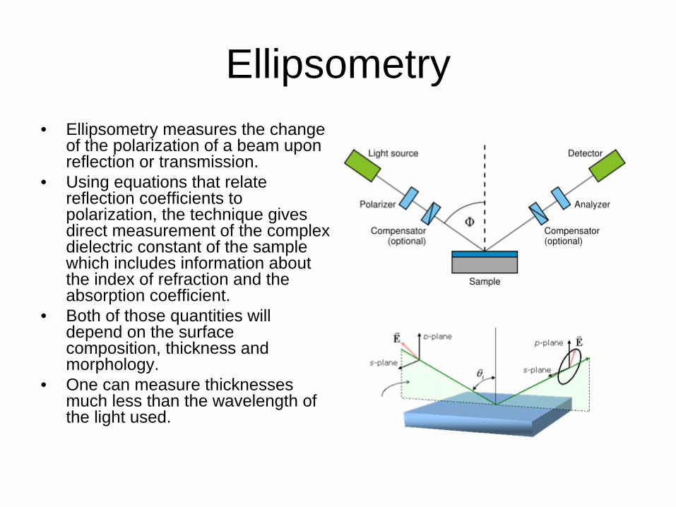
Ellipsometry• Ellipsometry measures the change
of the polarization of a beam upon reflection or transmission.
• Using equations that relate reflection coefficients to polarization, the technique gives direct measurement of the complex dielectric constant of the sample which includes information about the index of refraction and the absorption coefficient.
• Both of those quantities will depend on the surface composition, thickness and morphology.
• One can measure thicknesses much less than the wavelength of the light used.
Other Techniques
• The particular choice of excitation source and emission type will determine what the technique is sensitive to.
• Other than optical radiation, electron beams, x-rays and ion beams are available.
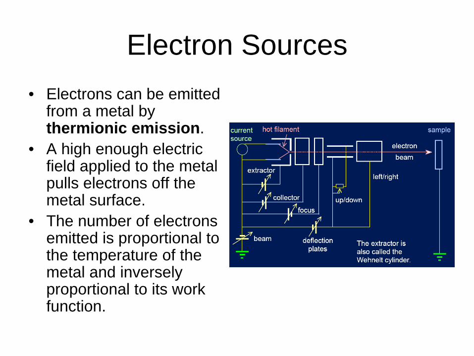
Electron Sources• Electrons can be emitted
from a metal by thermionic emission.
• A high enough electric field applied to the metal pulls electrons off the metal surface.
• The number of electrons emitted is proportional to the temperature of the metal and inversely proportional to its work function.
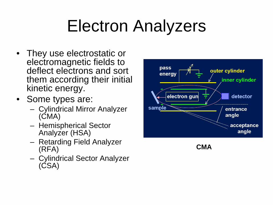
Electron Analyzers• They use electrostatic or
electromagnetic fields to deflect electrons and sort them according their initial kinetic energy.
• Some types are:– Cylindrical Mirror Analyzer
(CMA)– Hemispherical Sector
Analyzer (HSA)– Retarding Field Analyzer
(RFA)– Cylindrical Sector Analyzer
(CSA)
CMA
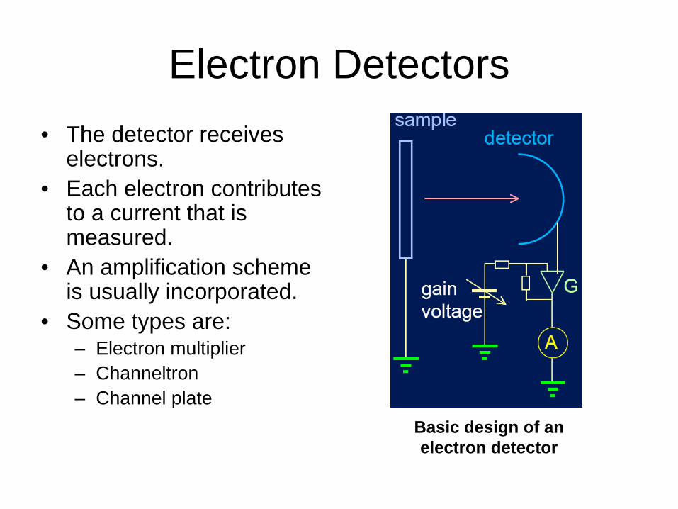
Electron Detectors• The detector receives
electrons.• Each electron contributes
to a current that is measured.
• An amplification scheme is usually incorporated.
• Some types are:– Electron multiplier– Channeltron– Channel plate
Basic design of an electron detector
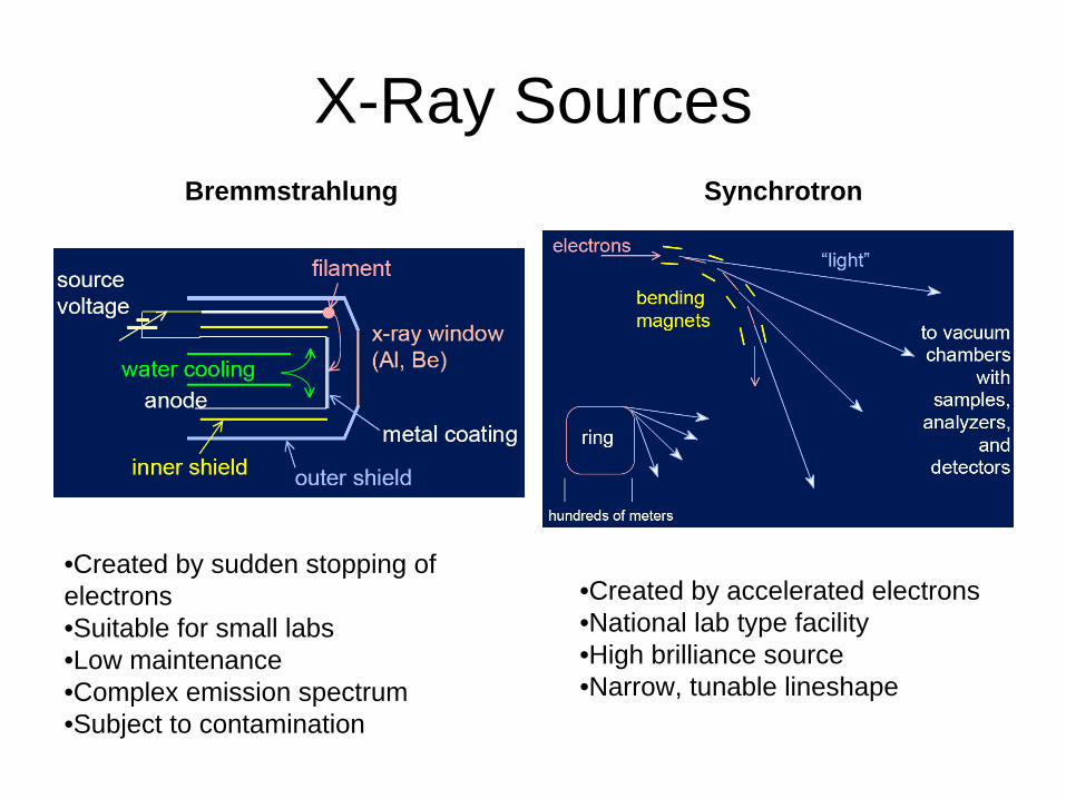
X-Ray SourcesBremmstrahlung Synchrotron
•Created by sudden stopping of electrons•Suitable for small labs•Low maintenance•Complex emission spectrum•Subject to contamination
•Created by accelerated electrons•National lab type facility•High brilliance source•Narrow, tunable lineshape
X-Ray Analyzers
• Wavelength Dispersive– Use a crystal and x-ray diffraction just ;like an
optical spectrometer.– Very sensitive and precise but expensive and
slow.• Energy Dispersive
– Use absorption in Si or Ge , generate multiple electron-hole pairs and separate them with an applied voltage.
– Faster and cheaper but less sensitive.
X-Ray Detectors
• Scintillators and phosphors– X-rays are absorbed as they penetrate the
detector and emit visible light.• Calorimeters
– X-rays are absorbed and the heat they produce is measured.
• Charge detectors– X-rays kick-off electrons from their orbits and
the resultant current is measured.
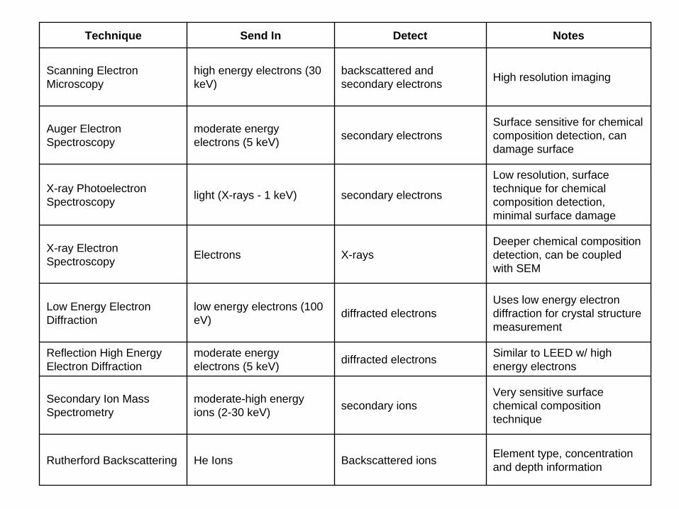
Technique Send In Detect Notes
Scanning Electron Microscopy
high energy electrons (30 keV)
backscattered and secondary electrons High resolution imaging
Auger Electron Spectroscopy
moderate energy electrons (5 keV) secondary electrons
Surface sensitive for chemical composition detection, can damage surface
X-ray Photoelectron Spectroscopy light (X-rays - 1 keV) secondary electrons
Low resolution, surface technique for chemical composition detection, minimal surface damage
X-ray Electron Spectroscopy Electrons X-rays
Deeper chemical composition detection, can be coupled with SEM
Low Energy Electron Diffraction
low energy electrons (100 eV) diffracted electrons
Uses low energy electron diffraction for crystal structure measurement
Reflection High Energy Electron Diffraction
moderate energy electrons (5 keV) diffracted electrons Similar to LEED w/ high
energy electrons
Secondary Ion Mass Spectrometry
moderate-high energy ions (2-30 keV) secondary ions
Very sensitive surface chemical composition technique
Rutherford Backscattering He Ions Backscattered ions Element type, concentration and depth information
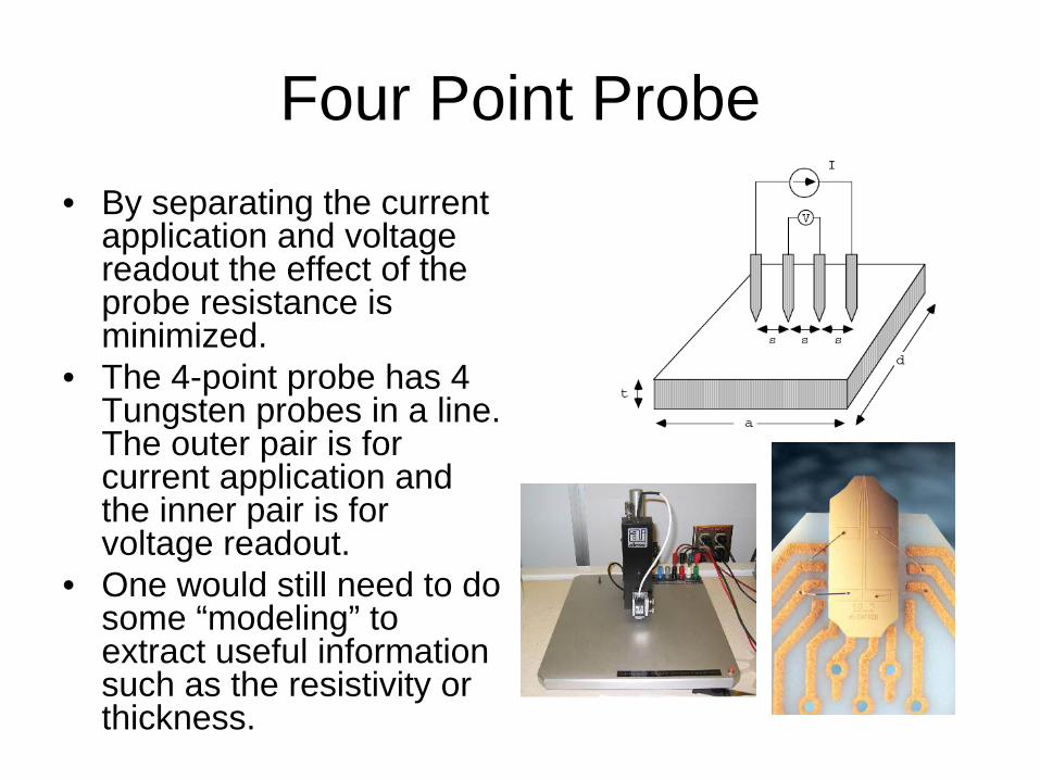
Four Point Probe• By separating the current
application and voltage readout the effect of the probe resistance is minimized.
• The 4-point probe has 4 Tungsten probes in a line. The outer pair is for current application and the inner pair is for voltage readout.
• One would still need to do some “modeling” to extract useful information such as the resistivity or thickness.
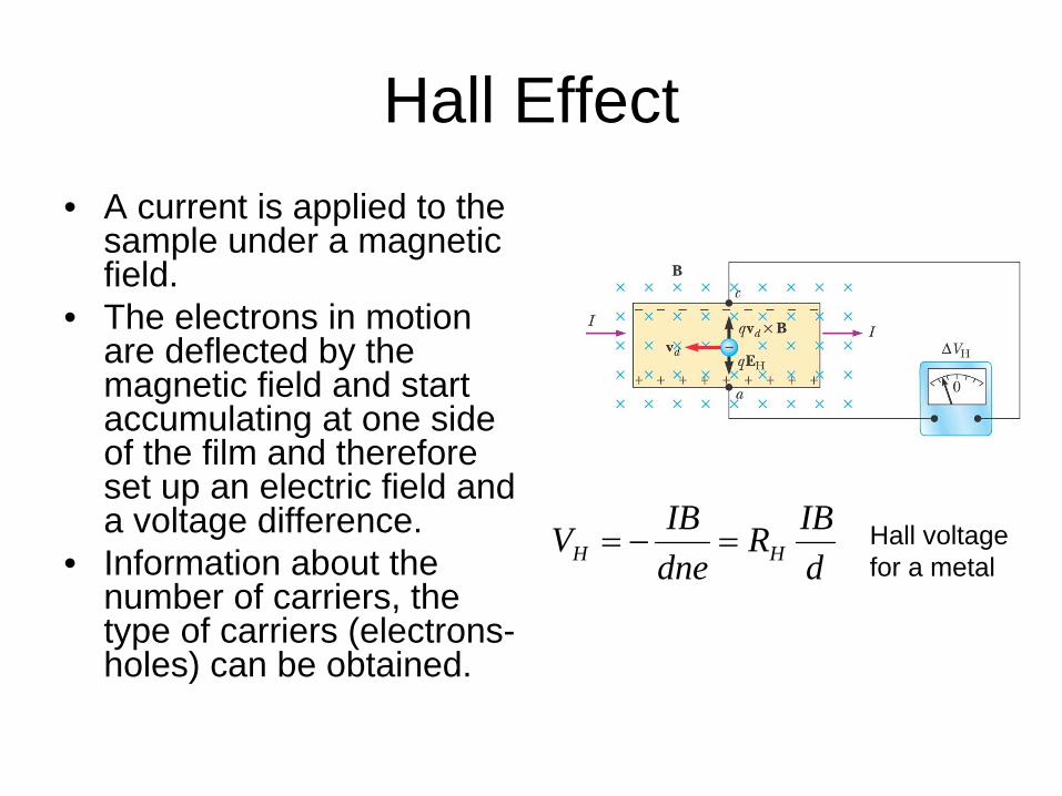
Hall Effect• A current is applied to the
sample under a magnetic field.
• The electrons in motion are deflected by the magnetic field and start accumulating at one side of the film and therefore set up an electric field and a voltage difference.
• Information about the number of carriers, the type of carriers (electrons- holes) can be obtained.
dIBR
dneIBV HH =−= Hall voltage
for a metal
Mechanical Measurements
• Internal - Residual Stress• Indentation• Friction and wear• Adhesion