
Micro-VersaTRAK μIPm™ RTU and Datalogger
25
Micro-VersaTRAK ® μIPm™ RTU and Datalogger Installation and Maintenance User Manual This manual applies to the following Sixnet products: VT-UIPM-XXX-H Micro-VersaTRAK μIPm RTU Note: In this manual, this unit is also referred to as the Micro-IPm or μIPm. Buy: www.ValinOnline.com | Phone 844-385-3099 | Email: [email protected]
Transcript of Micro-VersaTRAK μIPm™ RTU and Datalogger
1
Micro-VersaTRAK® μIPm™ RTU and Datalogger
Installation and Maintenance User Manual
This manual applies to the following Sixnet products: VT-UIPM-XXX-H Micro-VersaTRAK μIPm RTU Note: In this manual, this unit is also referred to as the Micro-IPm or μIPm.
Buy: www.ValinOnline.com | Phone 844-385-3099 | Email: [email protected]

CHANGE HISTORY Version Date Description
01/10/2014 Added French translations for Installation and Hazardous Area Warnings 02/25/2014 Changes to the Environmental Specifications 04/17/2014 Updated operating systems requirements.
Buy: www.ValinOnline.com | Phone 844-385-3099 | Email: [email protected]
TABLE OF CONTENTS 1 Overview ............................................................................................................................................................6
1.1 Introduction ........................................................................................................................................................... 61.2 Quick Getting Started Guide .................................................................................................................................. 61.3 Red Lion Software Tools ........................................................................................................................................ 71.4 Using Red Lion Windows Software ........................................................................................................................ 8
2 Assembly and Installation .................................................................................................................................. 102.1 Panel Assembly .................................................................................................................................................... 10
3 Power Supply Wiring ......................................................................................................................................... 123.1 Current Requirements ......................................................................................................................................... 13
4 I/O Wiring ......................................................................................................................................................... 144.1 On-board I/O Overview ....................................................................................................................................... 144.2 Discrete Inputs ..................................................................................................................................................... 144.3 Discrete Outputs .................................................................................................................................................. 144.4 Analog Inputs ....................................................................................................................................................... 15
5 Communications ............................................................................................................................................... 175.1 Communication Ports .......................................................................................................................................... 17
5.1.1 RS232 Port B ................................................................................................................................................... 175.1.2 RS232 Ports C & D.......................................................................................................................................... 185.1.3 RS485 Port A ................................................................................................................................................... 195.1.4 Ethernet Port ................................................................................................................................................... 20
6 Technical Specifications ..................................................................................................................................... 217 Maintenance Information .................................................................................................................................. 24
7.1 Local Diagnostics ................................................................................................................................................. 247.2 Power and Status LED .......................................................................................................................................... 247.3 Controller or RTU Memory .................................................................................................................................. 24
8 Service Information ........................................................................................................................................... 258.1 Product Support .................................................................................................................................................. 25
Buy: www.ValinOnline.com | Phone 844-385-3099 | Email: [email protected]

STATEMENT OF LIMITED WARRANTY
Red Lion, manufacturer of SixTRAK, VersaTRAK, RemoteTRAK and EtherTRAK products, warrants to Buyer that products manufactured by Red Lion will be free from defects in material and workmanship. Red Lion’s obligation under this warranty will be limited to repairing or replacing, at Red Lion’s option, the defective parts within 1 year of the date of installation, or within 18 months of the date of shipment from the point of manufacture, whichever is sooner. Products may be returned by Buyer only after permission has been obtained from Red Lion. Buyer will prepay all freight charges to return any products to the repair facility designated by Red Lion.
This limited warranty does not cover losses or damages that occur in shipment to or from Buyer or due to improper installation, maintenance, misuse, neglect or any cause other than ordinary commercial or industrial applications, This limited warranty is in lieu of all other warranties whether oral or written, expressed or implied. Red Lion’s liability shall not exceed the price of the individual unit which is the basis of the claim. In no event shall Red Lion be liable for any loss of profits, loss of use of facilities or equipment or other indirect, incidental or consequential damages.
Buy: www.ValinOnline.com | Phone 844-385-3099 | Email: [email protected]

INSTALLATION AND HAZARDOUS AREA WARNINGS
These products should not be used to replace proper safety interlocking. No software-based device (or any other solid-state device) should ever be designed to be responsible for the maintenance of consequential equipment or personnel safety. In particular, Red Lion disclaims any responsibility for damages, either direct or consequential, that result from the use of this equipment in any application.
All power, input and output (I/O) wiring must be in accordance with Class I, Division 2 wiring methods and in accordance with the authority having jurisdiction. WARNING – EXPLOSION HAZARD – SUBSTITUTION OF COMPONENTS MAY IMPAIR SUITABILITY FOR CLASS 1, DIVISION 2. WARNING – EXPLOSION HAZARD – WHEN IN HAZARDOUS LOCATIONS, DISCONNECT POWER BEFORE REPLACING OR WIRING MODULES. WARNING – EXPLOSION HAZARD – DO NOT DISCONNECT EQUIPMENT UNLESS POWER HAS BEEN SWITCHED OFF OR THE AREA IS KNOWN TO BE NONHAZARDOUS.
These products are operator interface units to be used within control panels. These devices are intended for use in Class I, Division 2, Hazardous Locations, industrial control applications. The enclosure shall be suitable for the location. A minimum IP54 rated enclosure is needed for ATEX unless an equivalent degree of protection is supplied by the location.
These products are to be used within control panels in hazardous locations. The enclosure shall be suitable for this location. Hot-swapping is not for use in hazardous locations.
AVERTISSEMENTS POUR INSTALLATION ET ENDROITS DANGEREUXCes produits ne doivent pas être utilisés pour remplacer le verrouillage de sécurité approprié. Aucun dispositif basé sur un logiciel (ou tout autre dispositif à l'état solide) devraient jamais être conçus pour être responsable de l'entretien de l'équipement consécutifs ou la sécurité du personnel. En particulier, Red Lion décline toute responsabilité pour les dommages, directs ou indirects, résultant de l'utilisation de cet équipement dans n'importe quelle application.
Tout courant, câblage entrée et sortie (I / O) doit être conforme aux méthodes de câblage à la Classe I, Division 2 et conformément à l'autorité compétente.
AVERTISSEMENT – RISQUE D’EXPLOSION – LA SUBSTITUTION DE TOUT COMPOSANT PEUT NUIRE À LA CONFORMITÉ DE CLASSE I, DIVISION 2.
AVERTISSEMENT – RISQUE D’EXPLOSION – LORSQUE DANS DES ENDROITS DANGEREUX, DÉBRANCHEZ LE CORDON D'ALIMENTATION AVANT DE REMPLACER OU DE BRANCHER LES MODULES.
AVERTISSEMENT – RISQUE D’EXPLOSION – NE DÉBRANCHEZ PAS L'ÉQUIPEMENT À MOINS QUE L'ALIMENTATION AIT ÉTÉ COUPÉE OU QUE L’ENVIRONNEMENT EST CONNU POUR ÊTRE NON DANGEREUX.
Ces produits sont des unités d'interface opérateur qui doivent être utilisés à l'intérieur des panneaux de commande. Ces appareils sont destinés à une utilisation en Classe I, Division 2, Zones Dangereuses, applications de contrôle industriel. L'enclos doit être adapté à l’environnement.
Un boîtier IP54 minimum est nécessaire pour ATEX moins qu’un degré équivalent de protection est fourni par l'emplacement.
Ces produits doivent être utilisés dans des panneaux de contrôle lorsque dans des endroits dangereux. L'enclos doit être adapté à l’environnement. Pas de remplacement à chaud des modules dans les zones dangereuses
Note: All information in this document applies to the Micro-VersaTRAK μIPm RTU, except where otherwise noted. Refer to the
Buy: www.ValinOnline.com | Phone 844-385-3099 | Email: [email protected]

electronic help system in the Sixnet I/O Tool Kit software for detailed product specifications and configuration settings.
Overview 1.1 Introduction The products covered by this manual are designed for use in industrial control and data acquisition systems. Refer to the Red Lion Electronic catalog and the individual data sheets for complete features and benefits. This user manual covers the aspects of hardware installation and maintenance for the Micro-IPm. For software features and capabilities please refer to the electronic help system in the Sixnet I/O Tool Kit software.
A typical Red Lion station consists of an AC to DC power supply; a Red Lion controller or RTU (such as the models covered by this manual) and I/O modules. The Micro-IPm can interface with I/O modules via Ethernet (EtherTRAK I/O), or RS485 (RemoteTRAK or EtherTRAK I/O). Just about any combination of these components along with third party hardware and software can be used to make a system.
1.2 Quick Getting Started Guide Following these steps will make installation and start-up easier.
1. Mount the HardwareIf you purchased a TrakPak packaged system, the complete enclosure is ready for installation on any flat surface. If you purchased individual components, refer to the following sections of this manual or other appropriate user manuals for information on installing them into an enclosure. (See Section 2 for details)
2. Install Communication Wiring to I/O ModulesMake the necessary communication connections to any EtherTRAK I/O, RemoteTRAK I/O, or 3rd party devices. If you have a TrakPak packaged system, many of these connections have already been done for you. Otherwise, refer to the I/O module manuals as needed to establish the correct physical connections with the Micro-IPm.
3. Connect Power and I/O Wiring to On-board I/O and I/O ModulesConnect AC power to the Red Lion or user supplied power supply. Make DC power connections from the power supply to the Red Lion components. Make field wiring connections to the Red Lion I/O modules and any peripheral equipment. Refer to the Micro-IPm power and wiring diagram for making the appropriate power and on-board I/O connections.
4. Install Communication CablingThe units covered by this manual come with communication accessories. Snap the pre-wired RJ45 to DB9 adapter to the RJ45 patch cord (not supplied). Connect this cable between one of the serial RS232 ports (RJ45 connector) on your RTU and a serial RS232 port (DB9 connector) on your PC. More details about Ethernet, RS232 and RS485 wiring are provided in later sections. Fabricate and install RS232 and RS485 cables as needed to connect to other devices. If you are using Ethernet units, install the correct cabling and peripherals. Refer to the documentation for your Ethernet devices for details.
5. Apply PowerPower up the Red Lion components and related peripherals. Observe the PWR LED on the RTU. A solid
Buy: www.ValinOnline.com | Phone 844-385-3099 | Email: [email protected]
ON indicates proper operation. The Status LED on EtherTRAK and RemoteTRAK I/O modules should be ON solid or blinking, depending on whether I/O Transfers have been configured in the RTU. Refer to the appropriate Red Lion user manual for PWR/Status LED details.
6. Configure Using the Sixnet I/O Tool KitUse the Sixnet I/O Tool Kit to create a hardware configuration for each Red Lion station. Refer to the electronic help in the I/O Tool Kit for details.
7. Test the HardwareUse the Test I/O window in the I/O Tool Kit program to verify proper I/O operation of all Red Lion stations. Refer to the I/O Tool Kit help system.
8. Configure Your Software to Communicate with Red Lion station(s)Refer to the documentation for your software.
9. If You Have DifficultyIf you experience startup trouble, refer to Section 7 in this document for some troubleshooting tips or go to Red Lion website. If you still need assistance then please contact Red Lion.
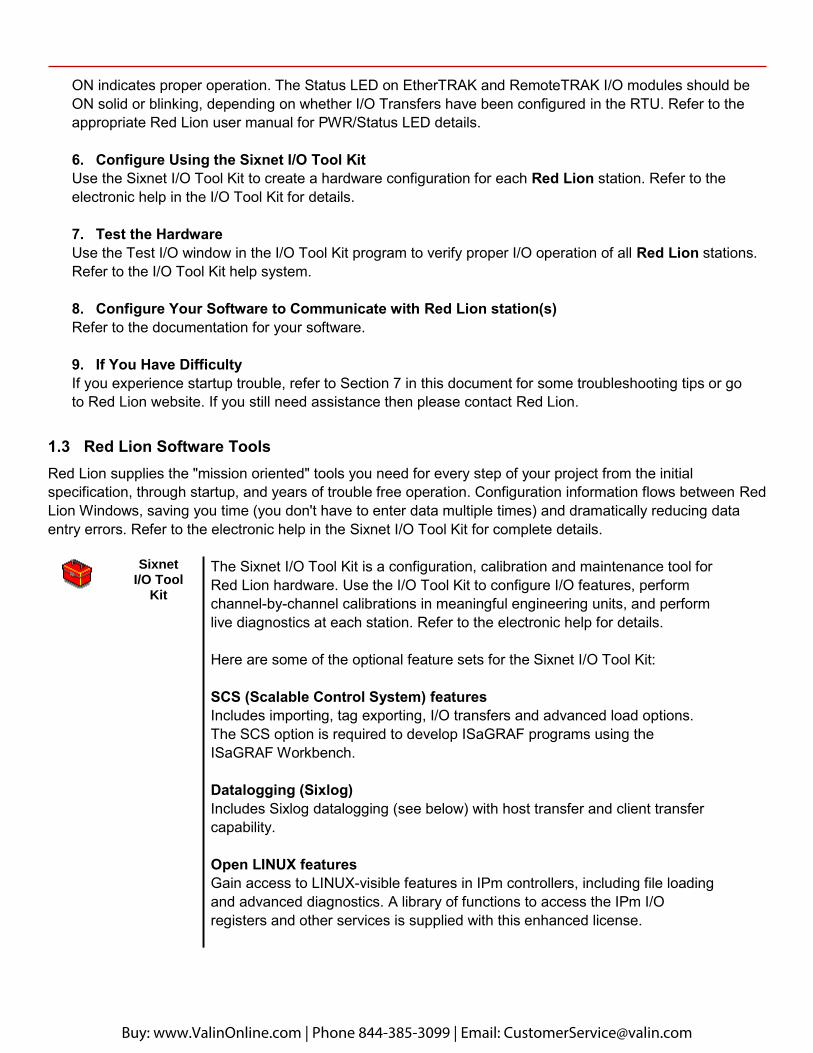
1.3 Red Lion Software Tools Red Lion supplies the "mission oriented" tools you need for every step of your project from the initial specification, through startup, and years of trouble free operation. Configuration information flows between Red Lion Windows, saving you time (you don't have to enter data multiple times) and dramatically reducing data entry errors. Refer to the electronic help in the Sixnet I/O Tool Kit for complete details.
Sixnet I/O Tool
Kit
The Sixnet I/O Tool Kit is a configuration, calibration and maintenance tool for Red Lion hardware. Use the I/O Tool Kit to configure I/O features, perform channel-by-channel calibrations in meaningful engineering units, and perform live diagnostics at each station. Refer to the electronic help for details.
Here are some of the optional feature sets for the Sixnet I/O Tool Kit:
SCS (Scalable Control System) features Includes importing, tag exporting, I/O transfers and advanced load options. The SCS option is required to develop ISaGRAF programs using the ISaGRAF Workbench.
Datalogging (Sixlog) Includes Sixlog datalogging (see below) with host transfer and client transfer capability.
Open LINUX features Gain access to LINUX-visible features in IPm controllers, including file loading and advanced diagnostics. A library of functions to access the IPm I/O registers and other services is supplied with this enhanced license.
Buy: www.ValinOnline.com | Phone 844-385-3099 | Email: [email protected]
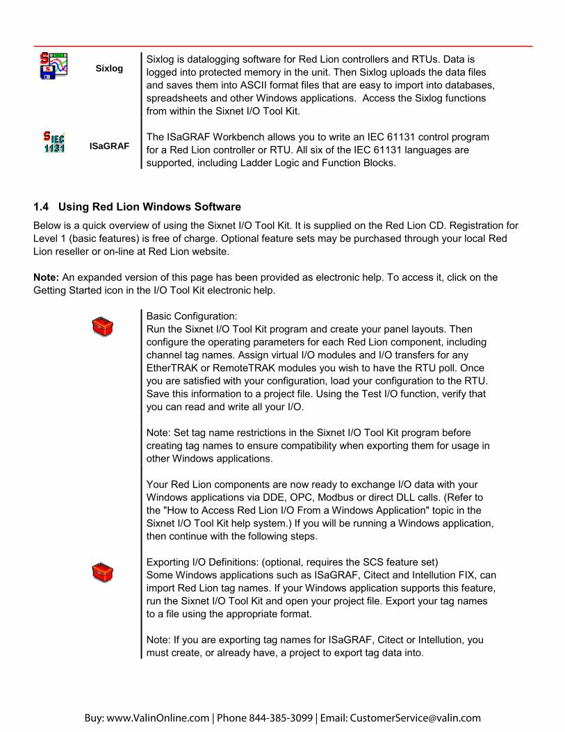
Sixlog Sixlog is datalogging software for Red Lion controllers and RTUs. Data is logged into protected memory in the unit. Then Sixlog uploads the data files and saves them into ASCII format files that are easy to import into databases, spreadsheets and other Windows applications. Access the Sixlog functions from within the Sixnet I/O Tool Kit.
ISaGRAF The ISaGRAF Workbench allows you to write an IEC 61131 control program for a Red Lion controller or RTU. All six of the IEC 61131 languages are supported, including Ladder Logic and Function Blocks.
1.4 Using Red Lion Windows Software Below is a quick overview of using the Sixnet I/O Tool Kit. It is supplied on the Red Lion CD. Registration for Level 1 (basic features) is free of charge. Optional feature sets may be purchased through your local Red Lion reseller or on-line at Red Lion website.
Note: An expanded version of this page has been provided as electronic help. To access it, click on the Getting Started icon in the I/O Tool Kit electronic help.
Basic Configuration: Run the Sixnet I/O Tool Kit program and create your panel layouts. Then configure the operating parameters for each Red Lion component, including channel tag names. Assign virtual I/O modules and I/O transfers for any EtherTRAK or RemoteTRAK modules you wish to have the RTU poll. Once you are satisfied with your configuration, load your configuration to the RTU. Save this information to a project file. Using the Test I/O function, verify that you can read and write all your I/O.
Note: Set tag name restrictions in the Sixnet I/O Tool Kit program before creating tag names to ensure compatibility when exporting them for usage in other Windows applications.
Your Red Lion components are now ready to exchange I/O data with your Windows applications via DDE, OPC, Modbus or direct DLL calls. (Refer to the "How to Access Red Lion I/O From a Windows Application" topic in the Sixnet I/O Tool Kit help system.) If you will be running a Windows application, then continue with the following steps.
Exporting I/O Definitions: (optional, requires the SCS feature set) Some Windows applications such as ISaGRAF, Citect and Intellution FIX, can import Red Lion tag names. If your Windows application supports this feature, run the Sixnet I/O Tool Kit and open your project file. Export your tag names to a file using the appropriate format.
Note: If you are exporting tag names for ISaGRAF, Citect or Intellution, you must create, or already have, a project to export tag data into.
Buy: www.ValinOnline.com | Phone 844-385-3099 | Email: [email protected]
Datalogging: (optional, requires the Datalogging feature set) If you will be logging data in the Red Lion RTU, then create the appropriate datalog configuration(s) and load them into the unit. Refer to the Sixlog topics in the Sixnet I/O Tool Kit help system for details.
IEC 61131 Programming: (optional, requires the SCS feature set) If you are using the ISaGRAF IEC1131 programming software, refer to the Red Lion ISaGRAF help system for detailed instructions.
LINUX capabilities: (optional, requires the IPm Advanced feature set) If you are using the advanced LINUX IPm capabilities, refer to the Sixnet I/O Tool Kit help for detailed instructions. IPm Advanced documentation and compilers are available for download from Red Lion website.
Buy: www.ValinOnline.com | Phone 844-385-3099 | Email: [email protected]
Wire Duct
Wire Duct
Wire Duct
Wire Duct
Wire
Duc
t
Wire
Duc
t
27.0" (68.6 cm)
33.0"(83.8 cm)
8.0"(20.3 cm)
6.5"(16.5 cm)
8.0"(20.3 cm)
8.0"(20.3 cm)
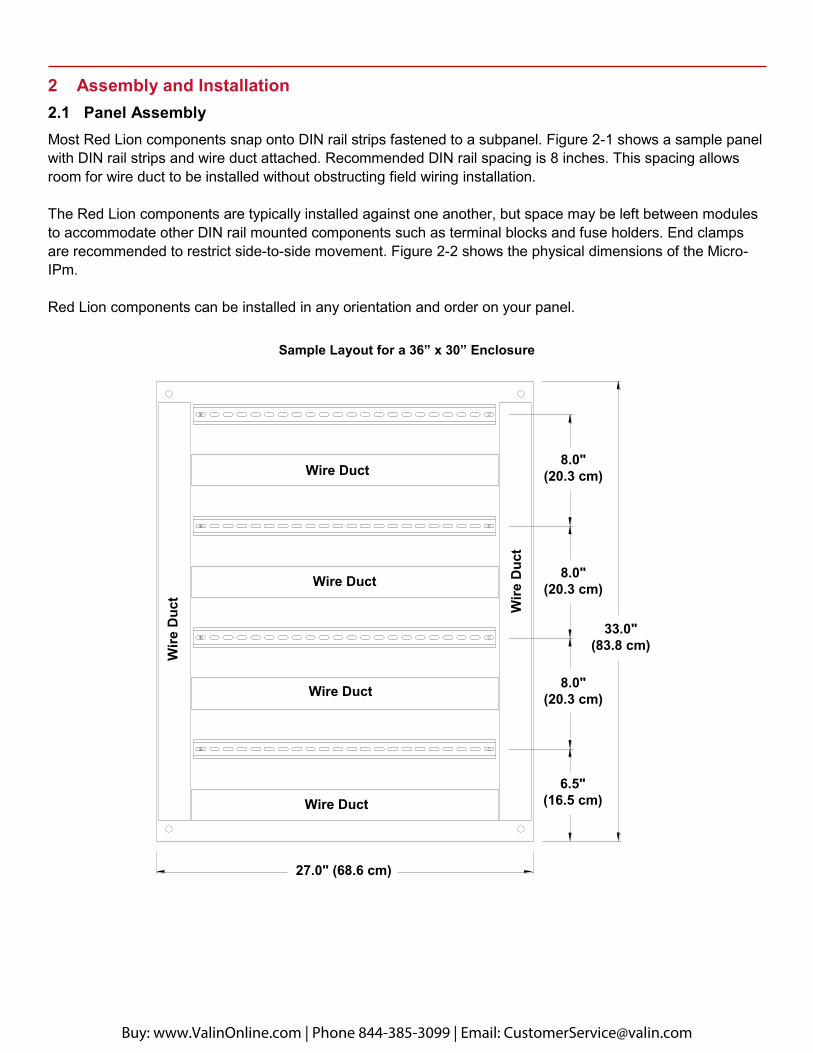
2 Assembly and Installation 2.1 Panel Assembly Most Red Lion components snap onto DIN rail strips fastened to a subpanel. Figure 2-1 shows a sample panel with DIN rail strips and wire duct attached. Recommended DIN rail spacing is 8 inches. This spacing allows room for wire duct to be installed without obstructing field wiring installation.
The Red Lion components are typically installed against one another, but space may be left between modules to accommodate other DIN rail mounted components such as terminal blocks and fuse holders. End clamps are recommended to restrict side-to-side movement. Figure 2-2 shows the physical dimensions of the Micro-IPm.
Red Lion components can be installed in any orientation and order on your panel.
Sample Layout for a 36” x 30” Enclosure
Buy: www.ValinOnline.com | Phone 844-385-3099 | Email: [email protected]
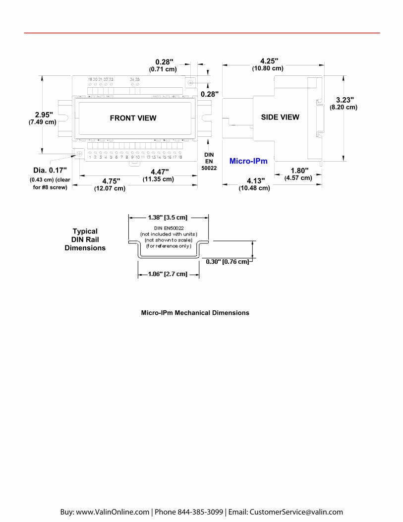
Micro-IPm Mechanical Dimensions
2.95"(7.49 cm)
0.28"(0.71 cm)
4.25"(10.80 cm)
3.23"(8.20 cm)
1.80"(4.57 cm)4.13"
(10.48 cm)
4.47"(11.35 cm)4.75"
(12.07 cm)
0.28"
Dia. 0.17"(0.43 cm) (clear
for #8 screw)
DINEN
50022
FRONT VIEW SIDE VIEW
Typical DIN Rail
Dimensions
Micro-IPm
Buy: www.ValinOnline.com | Phone 844-385-3099 | Email: [email protected]
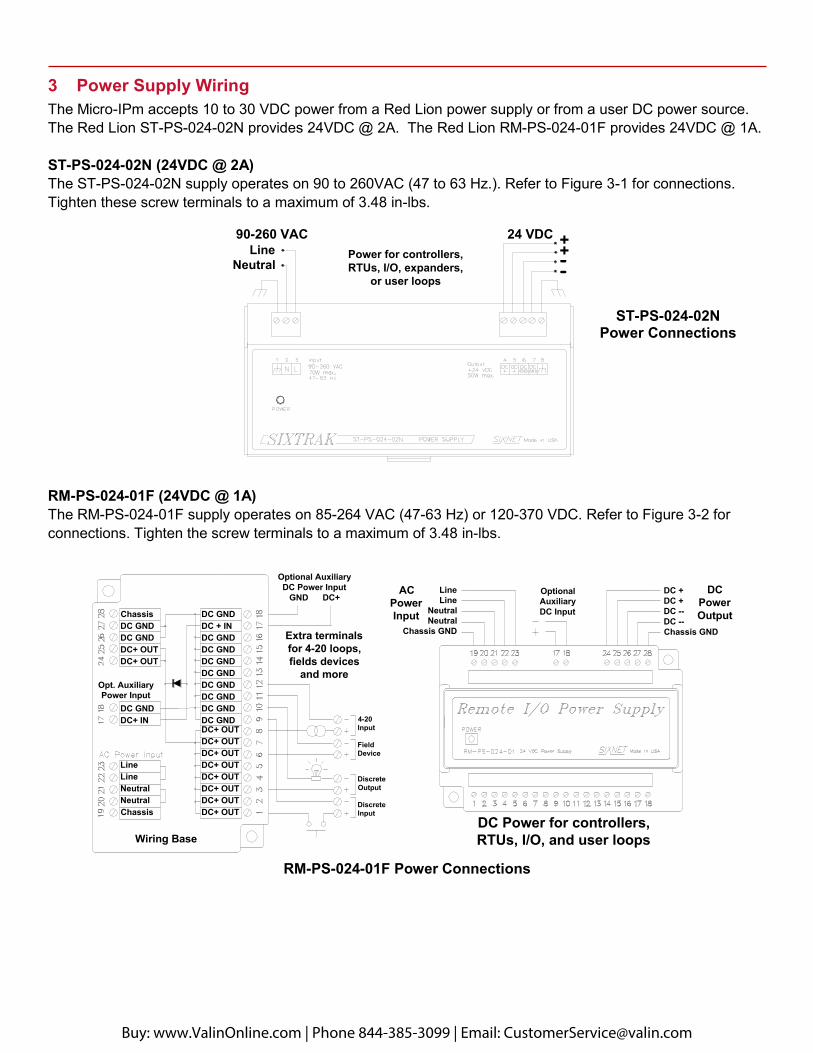
3 Power Supply Wiring The Micro-IPm accepts 10 to 30 VDC power from a Red Lion power supply or from a user DC power source. The Red Lion ST-PS-024-02N provides 24VDC @ 2A. The Red Lion RM-PS-024-01F provides 24VDC @ 1A.
ST-PS-024-02N (24VDC @ 2A) The ST-PS-024-02N supply operates on 90 to 260VAC (47 to 63 Hz.). Refer to Figure 3-1 for connections. Tighten these screw terminals to a maximum of 3.48 in-lbs.
RM-PS-024-01F (24VDC @ 1A) The RM-PS-024-01F supply operates on 85-264 VAC (47-63 Hz) or 120-370 VDC. Refer to Figure 3-2 for connections. Tighten the screw terminals to a maximum of 3.48 in-lbs.
ST-PS-024-02N Power Connections
RM-PS-024-01F Power Connections
90-260 VACPower for controllers,RTUs, I/O, expanders,
or user loops
LineNeutral
++----
24 VDC
LineLine
NeutralNeutral
Chassis GND
DC +DC +DC --DC --Chassis GND
OptionalAuxiliaryDC Input
ACPowerInput
DCPowerOutput
DC Power for controllers, RTUs, I/O, and user loops
Optional AuxiliaryDC Power Input
GND DC+
Extra terminalsfor 4-20 loops,fields devices
and more
DC GNDDC + INDC GNDDC GNDDC GNDDC GNDDC GNDDC GNDDC GNDDC GNDDC+ OUTDC+ OUTDC+ OUTDC+ OUTDC+ OUTDC+ OUTDC+ OUTDC+ OUT
ChassisDC GNDDC GNDDC+ OUTDC+ OUT
DC GNDDC+ IN
LineLineNeutralNeutralChassis
4-20Input
FieldDevice
DiscreteOutput
DiscreteInput
Wiring Base
Opt. AuxiliaryPower Input
Buy: www.ValinOnline.com | Phone 844-385-3099 | Email: [email protected]

RM-PS-024-01F Redundant Power The RM-PS-024-01F allows you to connect auxiliary 24 VDC power (from another RM-PS-024-01F or other source) to terminals 17 and 18. When auxiliary power is connected, the RM-PS-024-01F will source most of the power under normal operating conditions. If the primary power fails then the auxiliary power will immediately take over.
3.1 Current Requirements To calculate the current requirements, add the wattage required for all the units to be powered. Then divide this by the DC power source voltage (typically 24 VDC) to get the steady state current requirement. To allow for startup surge we recommend that you size your power source so that it rated for at least twice what you need for a steady state current.
DC Power Wiring All Red Lion units and user instrumentation loops may be powered from a single DC source. Refer to Figure 4-1 for DC power connections to the Micro-IPm. The user DC power source must be in the range of 10 to 30 volts.
Buy: www.ValinOnline.com | Phone 844-385-3099 | Email: [email protected]
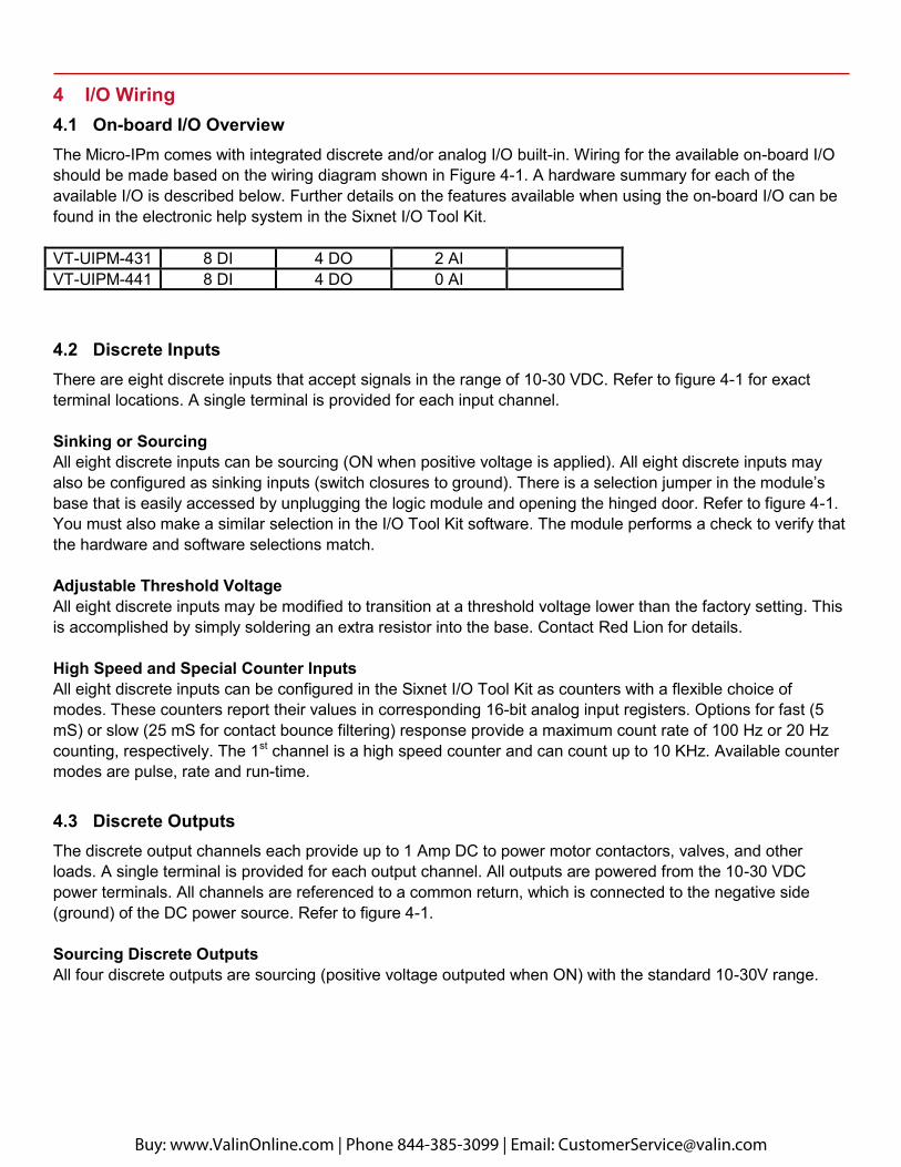
4 I/O Wiring 4.1 On-board I/O Overview The Micro-IPm comes with integrated discrete and/or analog I/O built-in. Wiring for the available on-board I/O should be made based on the wiring diagram shown in Figure 4-1. A hardware summary for each of the available I/O is described below. Further details on the features available when using the on-board I/O can be found in the electronic help system in the Sixnet I/O Tool Kit.
VT-UIPM-431 8 DI 4 DO 2 AI VT-UIPM-441 8 DI 4 DO 0 AI
4.2 Discrete Inputs There are eight discrete inputs that accept signals in the range of 10-30 VDC. Refer to figure 4-1 for exact terminal locations. A single terminal is provided for each input channel.
Sinking or Sourcing All eight discrete inputs can be sourcing (ON when positive voltage is applied). All eight discrete inputs may also be configured as sinking inputs (switch closures to ground). There is a selection jumper in the module’s base that is easily accessed by unplugging the logic module and opening the hinged door. Refer to figure 4-1. You must also make a similar selection in the I/O Tool Kit software. The module performs a check to verify that the hardware and software selections match.
Adjustable Threshold Voltage All eight discrete inputs may be modified to transition at a threshold voltage lower than the factory setting. This is accomplished by simply soldering an extra resistor into the base. Contact Red Lion for details.
High Speed and Special Counter Inputs All eight discrete inputs can be configured in the Sixnet I/O Tool Kit as counters with a flexible choice of modes. These counters report their values in corresponding 16-bit analog input registers. Options for fast (5 mS) or slow (25 mS for contact bounce filtering) response provide a maximum count rate of 100 Hz or 20 Hz counting, respectively. The 1st channel is a high speed counter and can count up to 10 KHz. Available counter modes are pulse, rate and run-time.
4.3 Discrete Outputs The discrete output channels each provide up to 1 Amp DC to power motor contactors, valves, and other loads. A single terminal is provided for each output channel. All outputs are powered from the 10-30 VDC power terminals. All channels are referenced to a common return, which is connected to the negative side (ground) of the DC power source. Refer to figure 4-1.
Sourcing Discrete Outputs All four discrete outputs are sourcing (positive voltage outputed when ON) with the standard 10-30V range.
Buy: www.ValinOnline.com | Phone 844-385-3099 | Email: [email protected]
Watchdog Output The first discrete output can be configured to be a watchdog output. This system performance monitor will be ON if the output circuitry, CPU operation and internal communications are functioning normally.
4.4 Analog Inputs There are optionally two analog inputs on your Micro-IPm. These inputs provide 16 bits of resolution for precision analog measurements. A single input terminal is provided for each measurement channel. Care must be taken to externally provide a suitable instrumentation ground for these single ended input circuits. Precision 100 ohm current shunts beneath the hinged access door in the wiring base pass current and maintain loop integrity, even if the plug-in logic module is removed. Each analog channel has built in current protection circuitry, such that each channel open circuits before any circuit damage will occur.
Self-resetting Analog Input Protection Each 4-20 mA input channel has a 100 ohm, high precision (0.1 percent) shunt across its input to develop a 2 volt signal when a full scale 20 mA input is applied. These shunts are located in the module’s base, giving you the advantage of maintaining a continuous circuit even if the logic module is removed from the base. If excessive voltage is applied to an input, a self-resetting fuse will open to prevent the shunt from overheating.
Open Loop Detection on Analog Inputs The Micro-IPm can detect and report an open instrumentation loop on its analog inputs. By allowing the module to report a negative value if the current falls below 4 mA, low limit logic in your DCS, PLC, RTU or computer can signal the loss of current. To enable this feature, select the “Go Negative Below 4 mA” software setting for each channel.
Reading Voltage Analog Inputs For each analog input, jumpers may be moved to convert the channel from 4-20 mA to 0-5 V. For example, in the diagram below, we see that both jumpers for the AI1 channel are in the “down” position for 4-20 mA. If we want AI1 to be 0-5 V, both jumpers for that channel must be placed in the “up” position instead. In addition, voltage operation must also be configured in the I/O Tool Kit by selecting the appropriate range for the corresponding input. Additional, factory modifications to the base can be made to allow for 0-2V and 0-10V ranges. Contact Red Lion.
Buy: www.ValinOnline.com | Phone 844-385-3099 | Email: [email protected]
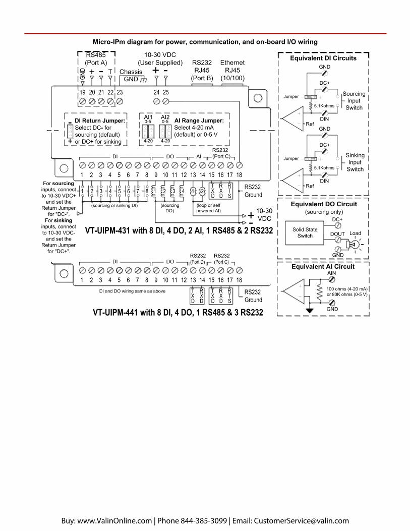
Micro-IPm diagram for power, communication, and on-board I/O wiring
Equivalent DI Circuits
Equivalent DO Circuit(sourcing only)
SourcingInput
Switch
SinkingInput
Switch
5.1Kohms
GND
DC+
DC+
GND
DIN
DOUT LoadSolid State
Switch
Ref
Jumper
GND
DC+
Jumper
5.1Kohms
DINRef
Equivalent AI Circuit
GND
AIN
100 ohms (4-20 mA)or 80K ohms (0-5 V)
RS232
Ground
RS232(Port C)
DXT
DXR
STR
GNDChassis
EthernetRJ45
(10/100)
(sourcing or sinking DI)
-DI Return Jumper:Select DC- forsourcing (default)or DC+ for sinking
+
10-30 VDC(User Supplied)
TG
ND + -
RS232RJ45
(Port B)
RS485(Port A)
(loop or selfpowered AI)
1
AIDI DO
212165432
2524
17 1815 1614
2321 2219 20
1210 11987653 421 13
VT-UIPM-431 with 8 DI, 4 DO, 2 AI, 1 RS485 & 2 RS232
3 47 8
10-30VDC
For sourcing inputs, connect to 10-30 VDC+
and set theReturn Jumper
for "DC-".For sinking
inputs, connect to 10-30 VDC-
and set theReturn Jumper
for "DC+".
(sourcingDO)
131 2 43 5 6 7 8 9 1110 12 14 1615 1817
RTS
RXD
TXD
RS232
Ground
DODIRS232(Port C)
DXR
DXT
RS232(Port D)
DI and DO wiring same as above
VT-UIPM-441 with 8 DI, 4 DO, 1 RS485 & 3 RS232
AI Range Jumper:Select 4-20 mA(default) or 0-5 V
0-5
4-20
AI1 AI2
4-20
0-5
Buy: www.ValinOnline.com | Phone 844-385-3099 | Email: [email protected]
5 Communications 5.1 Communication Ports The Micro-IPm has two available port combinations, depending on the model number. See the chart below.
Product RS485 Port A
RS232 Port B
RS232 Port C
RS232 Port D
Ethernet Port
VT-UIPM-431 -- VT-UIPM-441
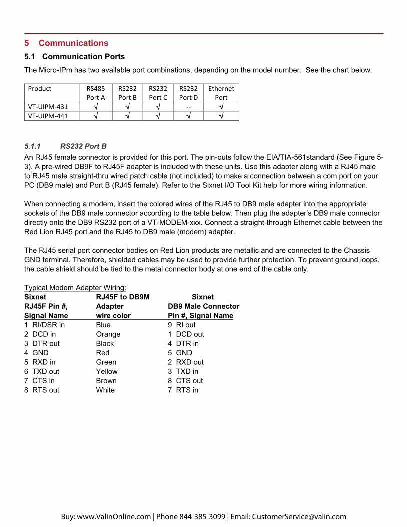
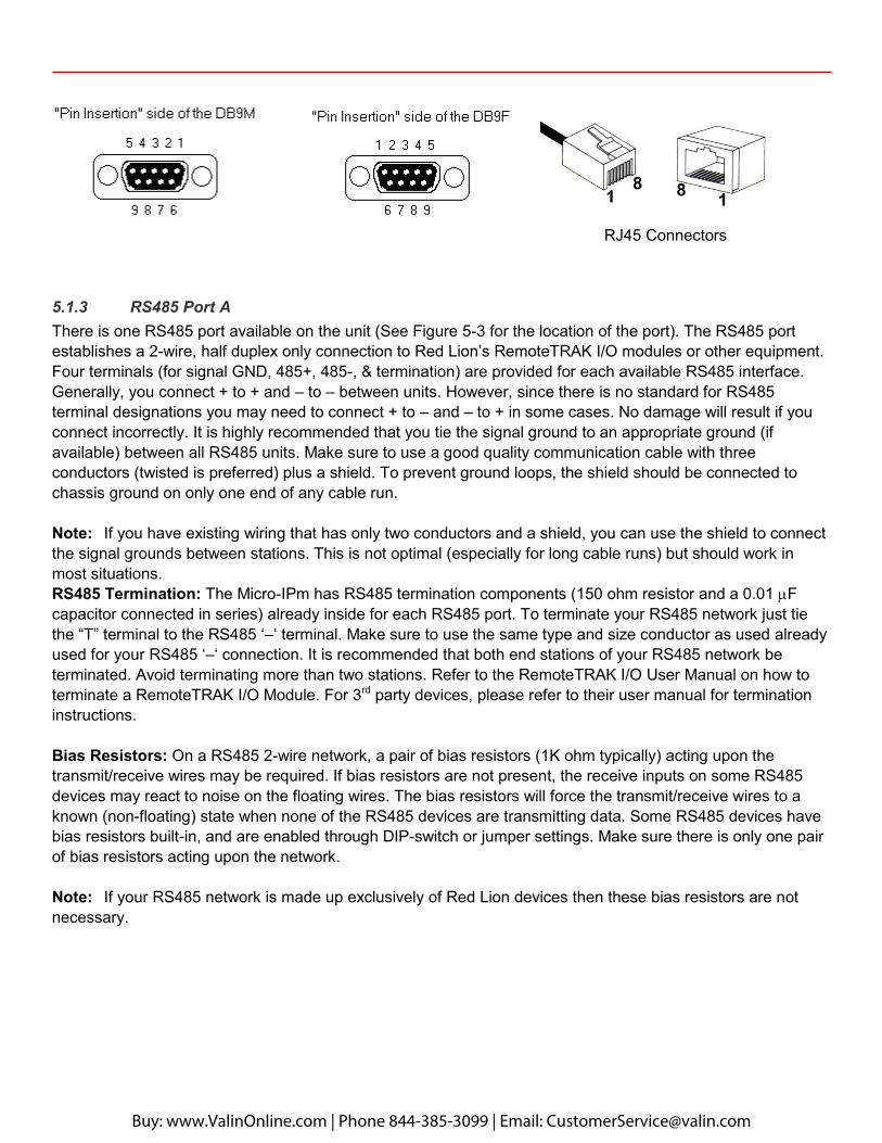
5.1.1 RS232 Port B An RJ45 female connector is provided for this port. The pin-outs follow the EIA/TIA-561standard (See Figure 5-3). A pre-wired DB9F to RJ45F adapter is included with these units. Use this adapter along with a RJ45 male to RJ45 male straight-thru wired patch cable (not included) to make a connection between a com port on your PC (DB9 male) and Port B (RJ45 female). Refer to the Sixnet I/O Tool Kit help for more wiring information.
When connecting a modem, insert the colored wires of the RJ45 to DB9 male adapter into the appropriate sockets of the DB9 male connector according to the table below. Then plug the adapter’s DB9 male connector directly onto the DB9 RS232 port of a VT-MODEM-xxx. Connect a straight-through Ethernet cable between the Red Lion RJ45 port and the RJ45 to DB9 male (modem) adapter.
The RJ45 serial port connector bodies on Red Lion products are metallic and are connected to the Chassis GND terminal. Therefore, shielded cables may be used to provide further protection. To prevent ground loops, the cable shield should be tied to the metal connector body at one end of the cable only.
Typical Modem Adapter Wiring: Sixnet RJ45F to DB9M Sixnet RJ45F Pin #, Adapter DB9 Male Connector Signal Name wire color Pin #, Signal Name 1 RI/DSR in Blue 9 RI out 2 DCD in Orange 1 DCD out 3 DTR out Black 4 DTR in 4 GND Red 5 GND 5 RXD in Green 2 RXD out 6 TXD out Yellow 3 TXD in 7 CTS in Brown 8 CTS out 8 RTS out White 7 RTS in
Buy: www.ValinOnline.com | Phone 844-385-3099 | Email: [email protected]

Typical PC Adapter Wiring: Sixnet RJ45F to DB9F RJ45F Pin #, Adapter DB9 Female Connector Signal Name wire color Pin #, Signal Name 1 RI/DSR in Blue 4 DTR out 2 DCD in Orange N/C 3 DTR out Black 6 DSR in 4 GND Red 5 GND 5 RXD in Green 3 TXD out 6 TXD out Yellow 2 RXD in 7 CTS in Brown 7 RTS out 8 RTS out White 8 CTS in
5.1.2 RS232 Ports C & D Port C is a four wire RS232 port with TXD, RXD, RTS and GND. Port D is a three wire RS232 port with TXD, RXD and GND. (The CTS signal is not supported on these ports. Use Port B if you need CTS.) Depending on your application, you may wish to wire the interface (see Figure 5-3) with a DB9 male or DB9 female connector. Figure 5-1 shows the pin-outs of male and female DB9 connectors.
Note: Terminal 18 is a common ground and is shared by both ports and the I/O.
There are two ways to connect Port C to a PC: Make connections from the μIPm screw terminals to a DB9F (female) connector and plug the female connector directly onto your PC. Make connections from the μIPm screw terminals to a DB9M (male) connector and plug the male connector onto one end of a Plant Floor RS232 cable (part number ST-CABLE-PF). Then plug the other end of the ST-CABLE-PF onto your PC. This wiring method allows you to plug the DB9M directly onto a VT-MODEM-xxx as well.
Make connections from the screw terminals of the Micro-IPm-xxx to a DB9 male or DB9 female connector according to table 5-1 below.
Micro-IPm-xxx-D DB9M to ST-CABLE-PF DB9F to Port C, D or VT-MODEM-xxx PC Com Port Terminal # Pin #, Signal Name Pin #, Signal Name 18 GND 5 GND 5 GND 16 RXD in 2 RXD 3 TXD 15 TXD out 3 TXD 2 RXD N/A 8 CTS 7 RTS 17 RTS out (port C only) 7 RTS 8 CTS
Buy: www.ValinOnline.com | Phone 844-385-3099 | Email: [email protected]
RJ45 Connectors
5.1.3 RS485 Port A There is one RS485 port available on the unit (See Figure 5-3 for the location of the port). The RS485 port establishes a 2-wire, half duplex only connection to Red Lion’s RemoteTRAK I/O modules or other equipment. Four terminals (for signal GND, 485+, 485-, & termination) are provided for each available RS485 interface. Generally, you connect + to + and – to – between units. However, since there is no standard for RS485 terminal designations you may need to connect + to – and – to + in some cases. No damage will result if you connect incorrectly. It is highly recommended that you tie the signal ground to an appropriate ground (if available) between all RS485 units. Make sure to use a good quality communication cable with three conductors (twisted is preferred) plus a shield. To prevent ground loops, the shield should be connected to chassis ground on only one end of any cable run.
Note: If you have existing wiring that has only two conductors and a shield, you can use the shield to connect the signal grounds between stations. This is not optimal (especially for long cable runs) but should work in most situations. RS485 Termination: The Micro-IPm has RS485 termination components (150 ohm resistor and a 0.01 F capacitor connected in series) already inside for each RS485 port. To terminate your RS485 network just tie the “T” terminal to the RS485 ‘–‘ terminal. Make sure to use the same type and size conductor as used already used for your RS485 ‘–‘ connection. It is recommended that both end stations of your RS485 network be terminated. Avoid terminating more than two stations. Refer to the RemoteTRAK I/O User Manual on how to terminate a RemoteTRAK I/O Module. For 3rd party devices, please refer to their user manual for termination instructions.
Bias Resistors: On a RS485 2-wire network, a pair of bias resistors (1K ohm typically) acting upon the transmit/receive wires may be required. If bias resistors are not present, the receive inputs on some RS485 devices may react to noise on the floating wires. The bias resistors will force the transmit/receive wires to a known (non-floating) state when none of the RS485 devices are transmitting data. Some RS485 devices have bias resistors built-in, and are enabled through DIP-switch or jumper settings. Make sure there is only one pair of bias resistors acting upon the network.
Note: If your RS485 network is made up exclusively of Red Lion devices then these bias resistors are not necessary.
Buy: www.ValinOnline.com | Phone 844-385-3099 | Email: [email protected]
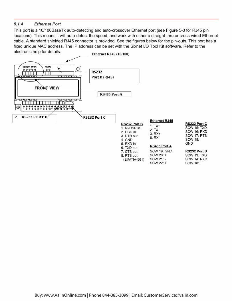
5.1.4 Ethernet Port This port is a 10/100BaseTx auto-detecting and auto-crossover Ethernet port (see Figure 5-3 for RJ45 pin locations). This means it will auto-detect the speed, and work with either a straight-thru or cross-wired Ethernet cable. A standard shielded RJ45 connector is provided. See the figures below for the pin-outs. This port has a fixed unique MAC address. The IP address can be set with the Sixnet I/O Tool Kit software. Refer to the electronic help for details.
RS485 Port A
Ethernet RJ45 (10/100)
RS232 Port C
RS232 Port B (RJ45)
RS232 Port B 1. RI/DSR in2. DCD in3. DTR out4. GND5. RXD in6. TXD out7. CTS out8. RTS out
(EIA/TIA-561)
Ethernet RJ45 1. TX+2. TX-3. RX+6. RX-
RS485 Port A SCW 19: GND SCW 20: + SCW 21: - SCW 22: T
RS232 Port C SCW 15: TXD SCW 16: RXD SCW 17: RTS SCW 18: GND
RS232 Port D SCW 13: TXD SCW 14: RXD SCW 18: GND
2 RS232 PORT D
Buy: www.ValinOnline.com | Phone 844-385-3099 | Email: [email protected]
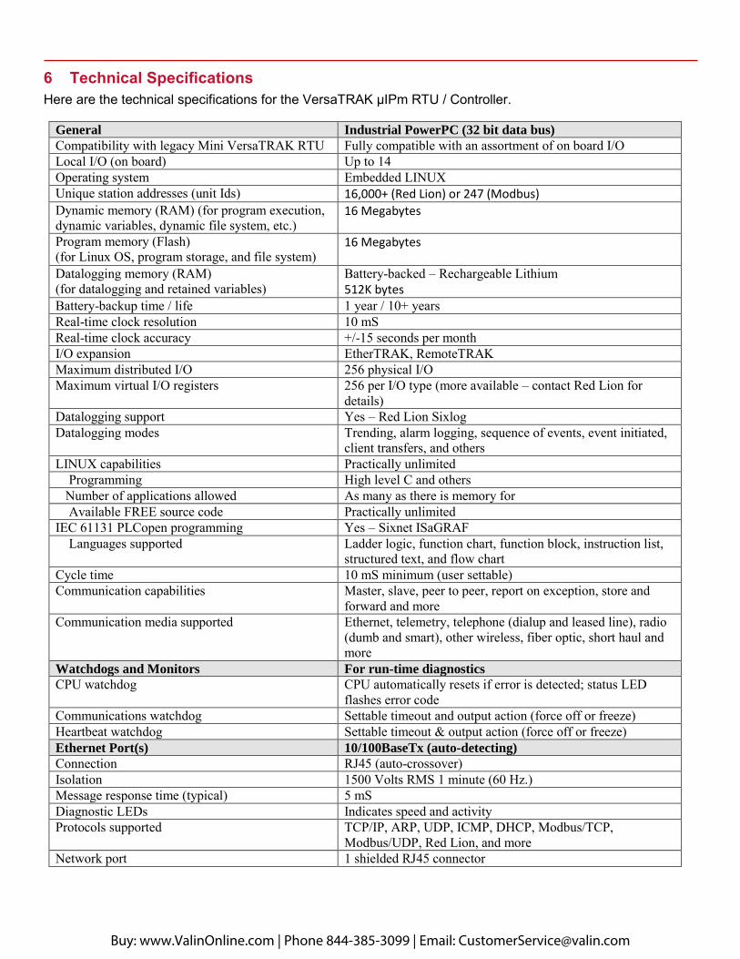
6 Technical Specifications Here are the technical specifications for the VersaTRAK μIPm RTU / Controller.
General Industrial PowerPC (32 bit data bus)
Compatibility with legacy Mini VersaTRAK RTU Fully compatible with an assortment of on board I/O Local I/O (on board) Up to 14 Operating system Embedded LINUX Unique station addresses (unit Ids) 16,000+ (Red Lion) or 247 (Modbus) Dynamic memory (RAM) (for program execution, dynamic variables, dynamic file system, etc.)
16 Megabytes
Program memory (Flash) (for Linux OS, program storage, and file system)
16 Megabytes
Datalogging memory (RAM) (for datalogging and retained variables)
Battery-backed – Rechargeable Lithium 512K bytes
Battery-backup time / life 1 year / 10+ years Real-time clock resolution 10 mS Real-time clock accuracy +/-15 seconds per month I/O expansion EtherTRAK, RemoteTRAK Maximum distributed I/O 256 physical I/O Maximum virtual I/O registers 256 per I/O type (more available – contact Red Lion for
details) Datalogging support Yes – Red Lion Sixlog Datalogging modes Trending, alarm logging, sequence of events, event initiated,
client transfers, and others LINUX capabilities Practically unlimited Programming High level C and others
Number of applications allowed As many as there is memory for Available FREE source code Practically unlimited IEC 61131 PLCopen programming Yes – Sixnet ISaGRAF Languages supported Ladder logic, function chart, function block, instruction list,
structured text, and flow chart Cycle time 10 mS minimum (user settable) Communication capabilities Master, slave, peer to peer, report on exception, store and
forward and more Communication media supported Ethernet, telemetry, telephone (dialup and leased line), radio
(dumb and smart), other wireless, fiber optic, short haul and more
Watchdogs and Monitors For run-time diagnostics
CPU watchdog CPU automatically resets if error is detected; status LED flashes error code
Communications watchdog Settable timeout and output action (force off or freeze) Heartbeat watchdog Settable timeout & output action (force off or freeze) Ethernet Port(s) 10/100BaseTx (auto-detecting)
Connection RJ45 (auto-crossover) Isolation 1500 Volts RMS 1 minute (60 Hz.) Message response time (typical) 5 mS Diagnostic LEDs Indicates speed and activity Protocols supported TCP/IP, ARP, UDP, ICMP, DHCP, Modbus/TCP,
Modbus/UDP, Red Lion, and more Network port 1 shielded RJ45 connector
Buy: www.ValinOnline.com | Phone 844-385-3099 | Email: [email protected]
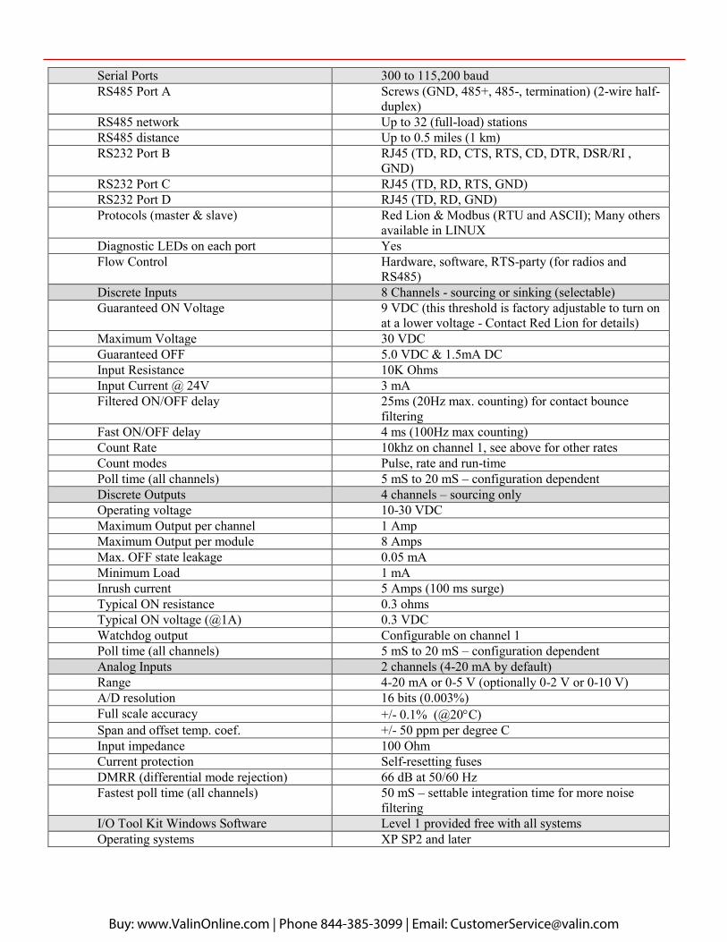
Serial Ports 300 to 115,200 baud RS485 Port A Screws (GND, 485+, 485-, termination) (2-wire half-
duplex) RS485 network Up to 32 (full-load) stations RS485 distance Up to 0.5 miles (1 km) RS232 Port B RJ45 (TD, RD, CTS, RTS, CD, DTR, DSR/RI ,
GND) RS232 Port C RJ45 (TD, RD, RTS, GND) RS232 Port D RJ45 (TD, RD, GND) Protocols (master & slave) Red Lion & Modbus (RTU and ASCII); Many others
available in LINUX Diagnostic LEDs on each port Yes Flow Control Hardware, software, RTS-party (for radios and
RS485) Discrete Inputs 8 Channels - sourcing or sinking (selectable) Guaranteed ON Voltage 9 VDC (this threshold is factory adjustable to turn on
at a lower voltage - Contact Red Lion for details) Maximum Voltage 30 VDC Guaranteed OFF 5.0 VDC & 1.5mA DC Input Resistance 10K Ohms Input Current @ 24V 3 mA Filtered ON/OFF delay 25ms (20Hz max. counting) for contact bounce
filtering Fast ON/OFF delay 4 ms (100Hz max counting) Count Rate 10khz on channel 1, see above for other rates Count modes Pulse, rate and run-time Poll time (all channels) 5 mS to 20 mS – configuration dependent Discrete Outputs 4 channels – sourcing only Operating voltage 10-30 VDC Maximum Output per channel 1 Amp Maximum Output per module 8 Amps Max. OFF state leakage 0.05 mA Minimum Load 1 mA Inrush current 5 Amps (100 ms surge) Typical ON resistance 0.3 ohms Typical ON voltage (@1A) 0.3 VDC Watchdog output Configurable on channel 1 Poll time (all channels) 5 mS to 20 mS – configuration dependent Analog Inputs 2 channels (4-20 mA by default) Range 4-20 mA or 0-5 V (optionally 0-2 V or 0-10 V) A/D resolution 16 bits (0.003%) Full scale accuracy +/- 0.1% (@20C) Span and offset temp. coef. +/- 50 ppm per degree C Input impedance 100 Ohm Current protection Self-resetting fuses DMRR (differential mode rejection) 66 dB at 50/60 Hz Fastest poll time (all channels) 50 mS – settable integration time for more noise
filtering I/O Tool Kit Windows Software Level 1 provided free with all systems Operating systems XP SP2 and later
Buy: www.ValinOnline.com | Phone 844-385-3099 | Email: [email protected]
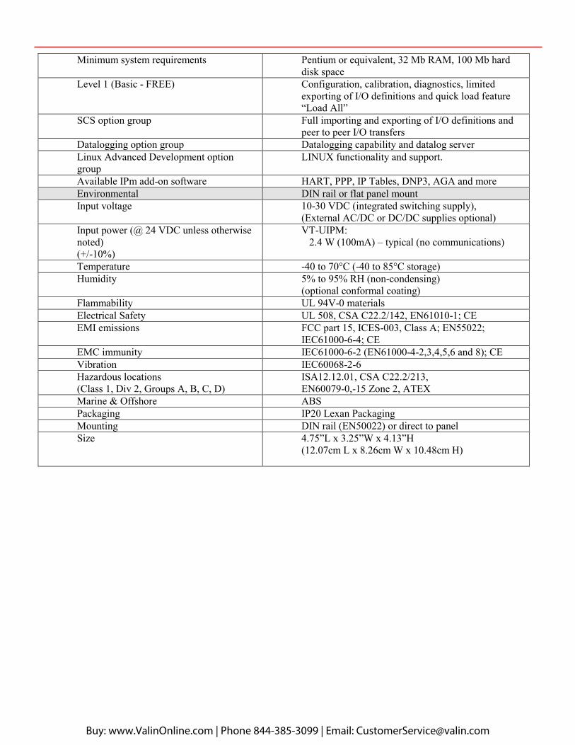
Minimum system requirements Pentium or equivalent, 32 Mb RAM, 100 Mb hard disk space
Level 1 (Basic - FREE) Configuration, calibration, diagnostics, limited exporting of I/O definitions and quick load feature “Load All”
SCS option group Full importing and exporting of I/O definitions and peer to peer I/O transfers
Datalogging option group Datalogging capability and datalog server Linux Advanced Development option group
LINUX functionality and support.
Available IPm add-on software HART, PPP, IP Tables, DNP3, AGA and more Environmental DIN rail or flat panel mount Input voltage 10-30 VDC (integrated switching supply),
(External AC/DC or DC/DC supplies optional) Input power (@ 24 VDC unless otherwise noted) (+/-10%)
VT-UIPM: 2.4 W (100mA) – typical (no communications)
Temperature -40 to 70°C (-40 to 85°C storage) Humidity 5% to 95% RH (non-condensing)
(optional conformal coating) Flammability UL 94V-0 materials Electrical Safety UL 508, CSA C22.2/142, EN61010-1; CE EMI emissions FCC part 15, ICES-003, Class A; EN55022;
IEC61000-6-4; CE EMC immunity IEC61000-6-2 (EN61000-4-2,3,4,5,6 and 8); CE Vibration IEC60068-2-6 Hazardous locations (Class 1, Div 2, Groups A, B, C, D)
ISA12.12.01, CSA C22.2/213, EN60079-0,-15 Zone 2, ATEX
Marine & Offshore ABS Packaging IP20 Lexan Packaging Mounting DIN rail (EN50022) or direct to panel Size 4.75”L x 3.25”W x 4.13”H
(12.07cm L x 8.26cm W x 10.48cm H)
Buy: www.ValinOnline.com | Phone 844-385-3099 | Email: [email protected]
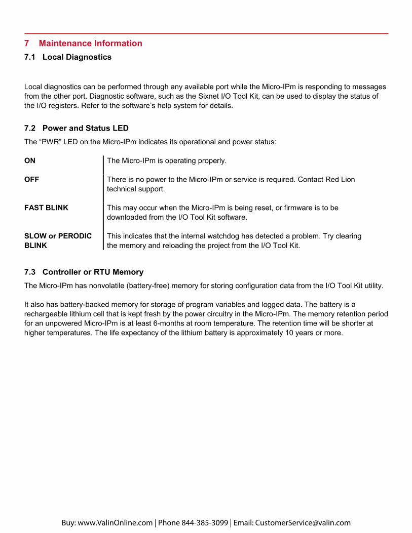
7 Maintenance Information 7.1 Local Diagnostics
Local diagnostics can be performed through any available port while the Micro-IPm is responding to messages from the other port. Diagnostic software, such as the Sixnet I/O Tool Kit, can be used to display the status of the I/O registers. Refer to the software’s help system for details.
7.2 Power and Status LED The “PWR” LED on the Micro-IPm indicates its operational and power status:
ON The Micro-IPm is operating properly.
OFF There is no power to the Micro-IPm or service is required. Contact Red Lion technical support.
FAST BLINK This may occur when the Micro-IPm is being reset, or firmware is to be downloaded from the I/O Tool Kit software.
SLOW or PERODIC BLINK
This indicates that the internal watchdog has detected a problem. Try clearing the memory and reloading the project from the I/O Tool Kit.
7.3 Controller or RTU Memory The Micro-IPm has nonvolatile (battery-free) memory for storing configuration data from the I/O Tool Kit utility.
It also has battery-backed memory for storage of program variables and logged data. The battery is a rechargeable lithium cell that is kept fresh by the power circuitry in the Micro-IPm. The memory retention period for an unpowered Micro-IPm is at least 6-months at room temperature. The retention time will be shorter at higher temperatures. The life expectancy of the lithium battery is approximately 10 years or more.
Buy: www.ValinOnline.com | Phone 844-385-3099 | Email: [email protected]

8 Service Information
We suggest that you give us a repair purchase order number in case the repair is not covered under our warranty. You will not be billed if the repair is covered under warranty.
Please supply us with as many details about the problem as you can. The information you supply will be written on the RO form and supplied to the repair department before your unit arrives. This helps us to provide you with the best service, in the fastest manner. Repairs are completed as soon as possible.in two days. If you need a quicker turnaround, ship the unit to us by air freight. We give priority service to equipment that arrives by overnight delivery.
We apologize for any inconvenience that the need for repair may cause you. We hope that our rapid service meets your needs. If you have any suggestions to help us improve our service, please give us a call. We appreciate your ideas and will respond to them.
Buy: www.ValinOnline.com | Phone 844-385-3099 | Email: [email protected]