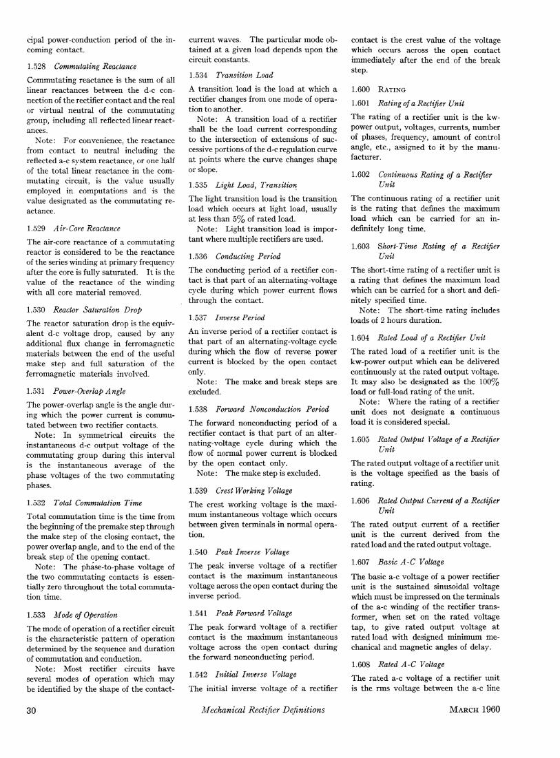
Mechanical rectifier definitions
7
2£ ic=— UI(1/25I2M) sin ut + Xd Xd / 8 (l/2«i23f)sin3«/+...] (14) 2£ i c = Ji(l/25 l2M )X Xd Γ . , , /2 12 ) . Ί sin ut-\ —; sin 3ut + ... L ^Λ(1/2 12 ) T J Equation 14 indicates that i c is not sin- usoidal but contains higher harmonics of decreasing amplitude. Fig. 7 shows the relative amplitudes of the fundamental and the harmonics of circulating current. For small variations in 5 Î2 the Bessel func- tion of the first order can be approximated by a series. 10 Equation 14, when restricted to the fundamental, becomes 2£ i c = — 7ι(1/2 12 )1/2 sin ut Xd = — 1/2 2Λ/ sin ut Xd in agreement with Fig. 5. Expressions for d- and g-axis components of i c can be found similarly from equations 10 and 12 7 · 8 · 9 - 10 . Eliminating intermediate results, the </-axis component is E E lcd=— [1-Λ( 2 )1 Λ( 2Λ ) 2xd Xd ( 0 x . Λ( 23/) . . . \ ,,_,. cos 2ut+— cos 4ut+ . . . ) (15) Λ( 2 ) / and the -axis component is sin ut-\ -sin3w/ + ^ Λ( 2 ) ) (16) The equations for i cq and i c are very sim- ilar except that the total angle S 12 M is used in one case and one half of the angle in the other case. Equation 22 for the ^-com- ponent is different, inasmuch as a d-c com- ponent exists. This cannot persist for steady-state conditions and the power sys- tem will approach an equilibrium through the closed-loop control actions indicated in Fig. 5 so that there is no d-c component. Nomenclature E = electromotive force i = current J(x) = Bessel function of first kind p = number of pole pairs s = Laplace operator T torque u = frequency of disturbance Xd = synchronous reactance = rotor angle 5i2 = rotor diplacement angle between two generators in parallel = power factor angle a>o = base speed SUBSCRIPTS 1 = machine 1 2 = machine 2 c = circulating d = direct-axis L = load q = quadrature-axis Ref. ererences 1. PARALLEL OPERATION OF AIRCRAFT A-C GEN- ERATORS: REACTIVE LOAD DIVISION AND SELECTIVE PROTECTION, H. A. Kahle. AIEE Transactions, pt. II (Applications and Industry), vol. 75, July 1956, pp. 175-81. 2. ANALOG COMPUTER REPRESENTATIONS OF AIRCRAFT PARALLEL ALTERNATING CURRENT GEN- ERATING SYSTEMS, L. V. Boffi, M. Riaz, P. E. Smith. WADC Technical Note 56-384, Wright Air Develop- ment Center, Dayton, Ohio, Sept. 1956. 3. ELECTRIC MACHINERY, M. Lischwitz, et.al. D. Van Nostrand Company, Inc., Princeton, N. J., vol. II, 1946. 4. ANALOG COMPUTER REPRESENTATIONS OF SYNCHRONOUS GENERATORS IN VOLTAGE-REGULA- TION STUDIES, M. Riaz. AIEE Transactions, pt. Ill (Power Apparatus and Systems), vol. 75, Dec. 1956, pp. 1178-84. 5. FREQUENCY MODULATION AND LOAD-DIVISION INSTABILITY IN 400-CYCLB AIRCRAFT ELECTRIC SYSTEMS, Henry Oman. Ibid.,\>t. II (Applications and Industry), vol. 75, July 1956, pp. 181-88. 6. DISCUSSION by H. M. McConnell of reference 5, pp. 185-86. 7. ORDINARY DIFFERENTIAL EQUATIONS (book), E. L. luce. Dover Publications, Inc., New York, N. Y., 1944. 8. HIGH FREQUENCY ALTERNATING CURRENT (book), K. Mcllwain, J. A. Brainard. John Wiley & Sons, Inc., New York, N.Y., 1939. 9. BESSEL FUNCTIONS FOR ENGINEERS (book), N. W., McLachlan. Oxford University Press, London, England, 1934. 10. ABHANDLUNGEN DER AKADEMIE FUER WISSEN- SCHAFTEN (book), Bessel. Berlin, Germany, 1824, p. 34. Mechanical Rectifier Definitions AIEE COMMITTEE REPORT W ORK ON mechanical rectifier standards was initiated by the Mechanical Rectifier Subcommittee in 1955. Because of the comparative new- ness and very rapid development of the mechanical rectifier, the work was slow and difficult. The first stumbling block, as in all standardization work, was en- countered in the matter of definitions, since no uniform terminology had de- veloped. The entire effort of the sub- committee was therefore concentrated on definitions. Before the work on definitions was com- pleted, it became obvious that production of mechanical rectifiers would soon come to an end because of the even more rapid development of semiconductor rectifiers with their economic and other advantages. The committee felt, however, that the work already in progress should be carried through, at least to the point of publish- ing a set of definitions and possibly a partial bibliography, which is appended to the definitions. It is the opinion of the subcommittee that the present installed capacity of mechanical rectifiers, the existence of con- siderable literature, the possible rebirth of this rectifier at some future time, and the possible application in other fields of t h e many useful circuits and devices de- veloped for the mechanical rectifier, all make it important to record and preserve Paper 60-35, recommended by the AIEE Industrial Power Rectifiers Committee and approved by the AIEE Technical Operations Department for pre- sentation at the AIEE Winter General Meeting, New York, N. Y., January 31-February 5, 1960. Manuscript submitted October 29, 1959; made available for printing December 4, 1959. The personnel of the AIEE Mechanical Rectifiers Subcommittee of the Industrial Power Rectifiers Committee are: I. K. DORTORT, chairman; John Chaumlak, D. C. Hoffmann, D. W. Human, Otto Jensen, N. A. Koss, Kenneth McCaskill, and J. C. Trackman. the work already accomplished. Knowl- edge of mechanical rectifiers and their circuits is very poorly distributed. We have attempted to make the definitions ed- ucational in the areas peculiar to mechan- ical rectifiers, so as to serve as a starting point for any future investigations. As a consequence, some of these definitions tend to be wordy and sometimes clumsy. Standards for Mechanical Rectifiers Section I. Definitions 1.000 SCOPE Definitions given herein apply partic- ularly to the type of mechanical rectifier in which groups of contacts are sequen- tially driven b y a synchronous motor. The so-called magnetic rectifier in which contacts are individually operated by electromagnets without any mechanical linkages between contacts is not specifi- cally covered in these definitions. Many of the terms, however, are applicable to both types. Only the rectifier part of the rectifier unit is covered. For the most part, 26 Mechanical Rectifier Definitions MARCH 1960
Transcript of Mechanical rectifier definitions

2 £ ic=— UI(1 /25 I2M) sin ut +
Xd Xd
/ 8 ( l / 2 « i 2 3 f ) s i n 3 « / + . . . ] (14)
2 £ ic = Ji(l/25l2M)X
Xd Γ . , , Μΐ/2δ12Μ) . Ί
sin ut-\ —; sin 3ut + . . . L ^Λ(1/2δ1 2 Μ) T J
Equation 14 indicates tha t ic is not sin-usoidal but contains higher harmonics of decreasing amplitude. Fig. 7 shows the relative amplitudes of the fundamental and the harmonics of circulating current. For small variations in 5Î2 the Bessel func-tion of the first order can be approximated by a series.10 Equation 14, when restricted to the fundamental, becomes
2 £ ic = — 7ι(1/2δ12Μ)1/2 sin ut
Xd
= — 1/2δΐ2Λ/ sin ut Xd
in agreement with Fig. 5. Expressions for d- and g-axis components
of ic can be found similarly from equations 10 and 127·8·9-10. Eliminating intermediate results, the </-axis component is
E E lcd=— [1-Λ(δΐ2Μ)1 Λ(δΐ2Λί)Χ
2xd Xd
( 0 x . Λ(δΐ23/) . . . \ , , _ , .
cos 2ut+— cos 4ut+ . . . ) (15) Λ(δΐ2Μ) /
and the ç-axis component is
sin ut-\ -sin3w/ + ^ Λ(δΐ2Μ)
■ ■ ■ ) (16)
The equations for icq and ic are very sim-ilar except that the total angle S12M is used in one case and one half of the angle in the other case. Equation 22 for the ^-com-ponent is different, inasmuch as a d-c com-ponent exists. This cannot persist for steady-state conditions and the power sys-tem will approach an equilibrium through the closed-loop control actions indicated in Fig. 5 so that there is no d-c component.
Nomenclature
E = electromotive force i = current J(x) = Bessel function of first kind p = number of pole pairs s = Laplace operator T—torque u = frequency of disturbance Xd = synchronous reactance δ = rotor angle 5i2 = rotor diplacement angle between two
generators in parallel φ = power factor angle a>o = base speed
SUBSCRIPTS
1 = machine 1 2 = machine 2 c = circulating d = direct-axis
L = load q = quadrature-axis
Ref. ererences
1. PARALLEL OPERATION OF AIRCRAFT A-C GEN-
ERATORS: REACTIVE LOAD DIVISION AND SELECTIVE
PROTECTION, H. A. Kahle. AIEE Transactions, pt. II (Applications and Industry), vol. 75, July 1956, pp. 175-81.
2. ANALOG COMPUTER REPRESENTATIONS OF
AIRCRAFT PARALLEL ALTERNATING CURRENT GEN-
ERATING SYSTEMS, L. V. Boffi, M. Riaz, P. E. Smith. WADC Technical Note 56-384, Wright Air Develop-ment Center, Dayton, Ohio, Sept. 1956.
3. ELECTRIC MACHINERY, M. Lischwitz, et.al. D.
Van Nostrand Company, Inc., Princeton, N. J., vol. II, 1946.
4. ANALOG COMPUTER REPRESENTATIONS OF
SYNCHRONOUS GENERATORS IN VOLTAGE-REGULA-
TION STUDIES, M. Riaz. AIEE Transactions, pt. I l l (Power Apparatus and Systems), vol. 75, Dec. 1956, pp. 1178-84.
5. FREQUENCY MODULATION AND LOAD-DIVISION
INSTABILITY IN 400-CYCLB AIRCRAFT ELECTRIC
SYSTEMS, Henry Oman. Ibid.,\>t. II (Applications and Industry), vol. 75, July 1956, pp. 181-88.
6. DISCUSSION by H. M. McConnell of reference 5, pp. 185-86.
7. ORDINARY DIFFERENTIAL EQUATIONS (book),
E. L. luce. Dover Publications, Inc., New York, N. Y., 1944.
8. HIGH FREQUENCY ALTERNATING CURRENT
(book), K. Mcllwain, J. A. Brainard. John Wiley & Sons, Inc., New York, N.Y., 1939.
9. BESSEL FUNCTIONS FOR ENGINEERS (book),
N. W., McLachlan. Oxford University Press, London, England, 1934.
10. ABHANDLUNGEN DER AKADEMIE FUER WISSEN-
SCHAFTEN (book), Bessel. Berlin, Germany, 1824, p. 34.
Mechanical Rectifier Definitions
AIEE COMMITTEE REPORT
WO R K ON mechanical rectifier s tandards was ini t iated by the
Mechanical Rectifier Subcommit tee in 1955. Because of the comparat ive new-ness and very rapid development of the mechanical rectifier, the work was slow and difficult. T h e first s tumbling block, as in all s tandardizat ion work, was en-countered in the ma t t e r of definitions, since no uniform terminology h a d de-veloped. T h e entire effort of t h e sub-committee was therefore concentrated on definitions.
Before the work on definitions was com-pleted, it became obvious t h a t production of mechanical rectifiers would soon come to an end because of the even more rapid development of semiconductor rectifiers with their economic and other advantages. The commit tee felt, however, t h a t the work already in progress should be carried through, a t least to the point of publish-
ing a set of definitions and possibly a partial bibliography, which is appended to the definitions.
I t is the opinion of the subcommit tee t h a t the present installed capacity of mechanical rectifiers, t he existence of con-siderable l i terature, t he possible rebir th of this rectifier a t some future t ime, and the possible application in other fields of the many useful circuits and devices de-veloped for the mechanical rectifier, all make it impor tan t to record and preserve
Paper 60-35, recommended by the AIEE Industrial Power Rectifiers Committee and approved by the AIEE Technical Operations Department for pre-sentation at the AIEE Winter General Meeting, New York, N. Y., January 31-February 5, 1960. Manuscript submitted October 29, 1959; made available for printing December 4, 1959.
The personnel of the AIEE Mechanical Rectifiers Subcommittee of the Industrial Power Rectifiers Committee are: I. K. DORTORT, chairman; John Chaumlak, D. C. Hoffmann, D. W. Human, Otto Jensen, N. A. Koss, Kenneth McCaskill, and J. C. Trackman.
the work already accomplished. Knowl-edge of mechanical rectifiers and their circuits is very poorly distr ibuted. We have a t t empted to make t he definitions ed-ucat ional in the areas peculiar to mechan-ical rectifiers, so as to serve as a s tar t ing point for any future investigations. As a consequence, some of these definitions tend to be wordy and sometimes clumsy.
Standards for Mechanical Rectifiers
Section I. Definitions
1.000 S C O P E
Definitions given herein apply par t ic-ularly to the type of mechanical rectifier in which groups of contacts are sequen-tially driven by a synchronous motor. The so-called magnet ic rectifier in which contacts are individually operated b y electromagnets wi thout any mechanical linkages between contacts is not specifi-cally covered in these definitions. M a n y of the terms, however, are applicable to bo th types.
Only the rectifier par t of the rectifier uni t is covered. For t he most part ,
26 Mechanical Rectifier Definitions M A R C H 1960
these definitions have been made consist-ent with the American Standard for pool cathode mercury-arc power converters *
Most of the symbols and circuits of C-34 are applicable as they relate to general rectifier circuitry. Symbols for the ex-citation circuits and properties of me-chanical rectifiers are so far from being standardized that it was not considered feasible to include them at this time.
1.100 EQUIPMENT TERMS
1.101 Mechanical Rectifier
A mechanical rectifier is an operable assembly of rectifier contacts and a recti-fier mechanism which drives the contacts in synchronism with the primary fre-quency, so that each contact completes a conductive circuit between an a-c and a d-c terminal during selected portions of each cycle. It includes all auxiliaries and control devices integrally housed or mounted between the a-c terminals of the rectifier and the d-c switchgear.
1.102 Mechanical Rectifier Unit
A mechanical rectifier unit is an operative assembly consisting of the mechanical rectifier(s), auxiliaries, commutating re-actors, the rectifier transformer, and essential switchgear.
1.103 Section of a Mechanical Rectifier Unit
A section of a mechanical rectifier unit is a part of a mechanical rectifier unit with its auxiliaries which may be operated independently of other sections of the unit.
1.104 Contact Power Converter
A contact power converter is an equip-ment which employs rectifier contacts for transforming electric power.
1.105 Contact Power Rectifier
A power rectifier is a rectifier unit in which the direction of average power flow is from the a-c circuit to the d-c circuit.
1.106 Contact Power Inverter
A power inverter is a rectifier unit in which the direction of average power flow is from the d-c circuit to the a-c circuit.
1.107 Contact Frequency Changer
A contact frequency changer is a contact power converter for changing the fre-quency of electric power.
1.200 RECTIFIER PARTS AND
AUXILIARIES
1.201 Rectifier Contact
A rectifier contact is a synchronously operated switch consisting of fixed and
movable contacts, structural parts, in-sulating, and spring members, which opens and closes a main power circuit between an a-c terminal and a d-c terminal at selected intervals of each cycle to perform the functions of rectification or inversion. A rectifier contact may or may not be an integral assembly.
1.202 Rectifier Mechanism
A rectifier mechanism is the mechanical apparatus which actuates the rectifier con-tacts in synchronism and proper phase relationship with the alternating voltage and each other.
1.203 Push Rod
A push rod is the direct actuating member which opens and closes the contacts in rectifier mechanisms employing lineal motion.
1.204 Commutating Reactor
A commutating reactor is a saturable re-actor connected in series with one or more rectifier contacts to provide a break and/ or make step. The instantaneous mag-netizing current must be small and substantially constant over a wide range of magnetization and speed of magnetiza-tion. It is generally equipped with control and bias windings.
1.205 Contact Protector
A contact protector is a high-speed switch used to bypass fault currents around the contacts of a mechanical rectifier.
1.206 Overlap Regulator
The overlap regulator is an assembly of components designed to maintain the break in its proper position in the break step by control of the mechanical overlap. It operates through the overlap adjusting means and/or the motor angle adjusting means.
1.207 Contact Time Meter
The contact time meter is an instrument and its circuitry designed to measure the dwell time, generally when the rectifier is not in service.
1.208 Overlap Meter
The overlap meter is an instrument and its circuitry designed to measure the angle of mechanical overlap, generally while the rectifier is in service.
1.209 Break Margin Meter
The break margin meter is an instrument and its circuitry designed to measure the overload margin or the load-dropping margin or to indicate position of the break within the break step.
1.210 Temperature Regulating Equipment
The temperature regulating equipment of a rectifier is any equipment used for cool-ing the rectifier, together with the devices for controlling and indicating its tempera-ture.
1.211 Cooling System
The cooling system of a rectifier is the equipment, i.e., parts and their inter-connections, used for cooling a rectifier. It includes all or some of the following: rectifier water jackets or tubes, water-cooled busses, cooling fins, heat ex-changers, blowers, pump, expansion tank, piping, insulating tubing, etc.
1.212 Natur al-Air Cooling System (of a Rectifier)
A natural-air cooling system is an air-cool-ing system in which heat is removed from the cooling surfaces of the rectifier only by the natural convection of the ambient air.
1.213 Forced-Air Cooling System (of a Rectifier)
A forced-air cooling system is an air-cool-ing system in which heat is removed from the cooling surface of the rectifier by means of a flow of air produced by a fan or blower.
1.214 Direct Raw-Water Cooling System
A direct raw-water cooling system of a rectifier is a cooling system in which water, received from a constantly avail-able supply such as a well or water system, is passed directly over the cooling surfaces of the rectifier and discharged.
1.215 Direct Raw-Water Recirculation Cooling System
A direct raw-water cooling system with re-circulation is a direct raw-water cooling system in which part of the water passing over the cooling surfaces of the rectifier is recirculated and raw water is added as needed to maintain the required tem-perature, the excess being discharged.
1.216 Heat-Exchanger Cooling System
A heat-exchanger cooling system of a rectifier is a cooling system in which the coolant, after passing over the cooling sur-faces of the rectifier, is cooled in a heat exchanger and recirculated.
1.300 RECTIFIER CIRCUITS
1.301 Single-Way Rectifier
A single-way rectifier is a rectifier in which the current between each terminal of the alternating voltage circuit and the recti-fier contact (or contacts) conductively
MARCH 1960 Mechanical Rectifier Definitions 27
connected to it flows only in one direc-tion.
1.302 Double- Way Rectifier
A double-way rectifier is a rectifier in which the current between each terminal of the alternating voltage circuit and the rectifier contacts conductively connected to it flows in both directions.
Note: The terms single-way and double-way provide a means for describ-ing the effect of the rectifier circuit on current flow in transformer windings con-nected to rectifiers. Most rectifier cir-cuits may be classified into these two general types.
1.303 Commutation
Commutation in a contact power con-verter is the transfer of current between contacts which conduct in succession.
1.304 Commutating Group
A commutating group of a contact power converter is a group of contacts and the alternating voltage supply elements con-ductively connected to them in which the direct current of the group is commutated between individual contacts which con-duct in succession.
1.305 Set of Commutating Groups
A set of commutating groups of a contact power converter consists of two or more commutating groups which have simul-taneous commutation.
1.306 Simple Rectifier
A simple rectifier is a rectifier consisting of one commutating group if single-way, or two if double-way.
1.307 Multiple Rectifier
A multiple rectifier is a rectifier in which two or more similar simple rectifiers are connected in such a way that their direct currents add, but their commutations do not coincide.
1.308 Cascade Rectifier
A cascade rectifier is a rectifier in which two or more simple rectifiers are connected in such a way that their d-c voltages add but their commutations do not coincide.
Note: When two or more rectifiers operate so that their commutations coincide, they are said to be in parallel if the direct currents add, and in series if the d-c voltages add.
1.309 Number of Rectifier Phases
The number of rectifier phases in a recti-fier circuit is equal to the total number of successive, nonsimultaneous commuta-tions occurring within the rectifier circuit
during each cycle when operating without phase control. It is also equal to the order of the principal harmonic in the d-c voltage waveshape.
Note: The number of rectifier phases influences both a-c and d-c circuit wave-form. In a simple single-way rectifier the number of rectifier phases is equal to the number of rectifier contacts.
1.400 EXCITATION AND CONTROL
CIRCUITS AND FUNCTIONS
1.401 Excitation Circuits
Excitation circuits are low-power auxiliary and control circuits and components designed to provide the proper conditions at the instants of contact make and break to avoid excessive material transfer and contact erosion. Included in this general term are excitation bias circuits, straight-ener circuits, flux-resetting circuits, and contact bypass circuits and components.
1.402 Excitation Bias Circuit
The excitation bias circuit is a circuit which provides the required ampere-turns to the commutating reactor during the break and/or make steps to adjust the value of the current in the main wind-ing to the desired level during the step. As in the normal usage of the term "bias," its value is held essentially constant, but may be varied manually or automatically
" to meet varying conditions. Note: Since, for the specified purpose,
the value of bias is of interest only during the step, direct, alternating, or pulse cur-rents may be used. Other functions are often assigned to the same auxiliary wind-ings and to the same circuits.
1.403 Straightener Circuit
A straightner circuit is the circuit and circuit elements used to correct for the variation of the magnetizing current of a commutating reactor during the break step.
1.404 Contact Bypass Circuit
A bypass circuit is a circuit connected to one or more rectifier contacts to provide a low-impedance path for the small residual current broken at the contact, together with the components required to prevent the flow of excessive current in the bypass circuit when the full inverse voltage or commutating voltage appears across the contact. It is essentially a spark-suppressor circuit, but sometimes performs other functions as well.
1.405 Excitation Bypass Circuit
An excitation bypass circuit is one which bypasses around the rectifier contact all
or most of the excitation current required by the commutating reactor during the break step so that the contact opens at essentially zero voltage and current. It also acts as a spark-suppressor by pro-viding a low-impedance path for any re-sidual current flowing through the contact at the instant of break.
1.406 Flux-Reset Circuits
The flux-reset circuit impresses across the commutating reactors a voltage of proper magnitude, duration, and phasing to effect a predetermined change in its flux density, after completion of the break step and be-fore contact make.
Note: The balance of flux not reset by the flux-reset circuit prior to contact make is reset by the commutating volt-age during the make step and determines the amount of magnetic phase control.
1.407 Phase Control
Phase control is the process of varying the point within the cycle at which con-duction of power current through a recti-fier contact is permitted to begin. By re-ducing the a-c voltage integrated into the average d-c voltage, the phase control regulates the d-c voltage of the recti-fier.
The amount of phase control may be expressed in two ways : 1. the reduction in d-c voltage obtained by phase control, or 2. the total angle of § phase retard (or advance).
1.408 Mechanical-Phase Control
Mechanical-phase control is the process of varying the mechanical-make point so as to control the point within the cycle at which conduction of power current through a rectifier contact is permitted to begin.
1.409 Magnetic-Phase Control
Magnetic-phase control is the process of varying by magnetic means the point within the cycle at which conduction of power current through a rectifier contact is permitted to begin after make.
1.410 Ballast Load
The ballast load is a small internally con-nected load sometimes required to preset the commutating reactor flux for the break step during periods of very light load.
1.500 FUNCTIONAL TERMS
1.501 Phase Transition
Phase transition is the instant at which the commutating voltage between two commutating phases increases through
28 Mechanical Rectifier Definitions M A R C H I960
zero in the direction to effect commuta-tion.
1.502 Make
Make is the point within the cycle at which the rectifier contacts close, meas-ured from the phase transition.
1.503 Break
Break is the point within the cycle at which the rectifier contacts open, meas-ured from the phase transition. (Com-mutating voltage decreasing in the sense to decrease power current in the opening contact.)
1.504 Dwell Time
Dwell time is the electrical angle in each cycle during which the rectifier contact is closed. It is equal to 360 degrees divided by the number of phases in the commutat-ing group plus the mechanical overlap angle.
1.505 Mechanical Overlap
Mechanical overlap is the electrical angle during which the contacts of similar polar-ity of two commutating phases are si-multaneously closed. It is equal to the dwell time less 360 degrees divided by the number of phases in the commutating group.
1.506 Premake Step
The premake step is the period just prior to the closing of the contact during which the flux of the commutating reactor is caused to change in a manner to reduce the voltage across the contact at the in-stant of closing.
1.507 Make Step
The make step is the period immediately following the closing of the contact during which the current through the contact is limited by the properties of the com-mutating reactor and associated circuits.
1.508 Break Step
The break step is the interval at the end of the conduction period during which the flux of the commutating reactor is re-versed from saturation in the forward direction to a predetermined value in the reverse direction. The current in the contact is limited to a very low value by the properties of the commutating reactor and associated circuits. The contact is generally opened near the middle of this low-current interval.
1.509 Rated-Step Length
The rated-step length of a break and/or make commutating reactor is the time required at rated peak commutating volt-
age to swing the core through the full useful range of flux density (during which time the magnetizing current is essen-tially constant).
1.510 Volt-Second Rating
The volt-second rating of a commutating reactor is the product of the rated peak commutating voltage and the rated step length. The integrated product of voltage and time is a constant of the re-actor design and is independent of the applied voltage.
Note:
Stl edt = A(B2-B1)NXlO^
where A is the iron cross section, Bi and B2 are the limits of useful flux density, and N the number of turns.
1.511 Speed of Magnetization
The speed of magnetization is the time rate of change of the flux density of a ferromagnetic core, specifically applied for the purpose of these standards, to the core of a commutating reactor. (It is equal at any instant to the voltage per-turn per-unit area times 108.)
1.512 Step Current
The step current of a commutating re-actor is the uncorrected magnetizing cur-rent of the commutating reactor during the make-or-break step.
Note: It varies with speed of mag-netization.
1.513 Residual-Break Current
The residual-break current is the modified contact current flowing in the contact immediately prior to the break.
1.514 Make Margin
The make margin is the time interval (expressed in electrical degrees) between the contact make and the end of the useful make step. If no premake step is used, the make margin is the minimum make step that can occur without changing fixed-circuit constants.
1.515 Overload Margin
Overload margin is the time interval be-tween the beginning of the useful break step and the contact break. I t is also a measure of a-c undervoltage margin.
1.516 Load-Dropping Margin
Load-dropping margin is the time inter-val between the contact break and the end of the useful break step. It is also a measure of the a-c overvoltage margin.
1.517 Make Voltage
The make voltage is the voltage across
the contact immediately before the make.
1.518 Make Current
Make current is the current flowing through the contact immediately after the make and before the contact is firmly seated.
1.519 Break Voltage
The break voltage is the voltage across the contact immediately after the break.
1.520 Break-Voltage Increase
The break-voltage increase is the increase of the voltage across the opening con-tact from the break voltage to the end of the break step, and before the rapid in-crease to the inverse voltage.
1.521 Recovery-Voltage Gap
The recovery-voltage gap is the open-ing between the contact members at the end of the break step^
1.522 Switching Speed
The switching speed of a contact is the velocity of the moving contact just prior to make and immediately after break. These speeds are equal if the contact motion is essentially harmonic.
1.523 Motor Angle
The motor angle is the angle by which the motor rotor is shifted from the phase position in which the midpoint of the contact dwell time would coincide exactly with a point halfway between two succes-sive phase transitions. It is equal to one-half the mechanical overlap angle if the contact motion is essentially harmonic.
1.524 Mechanical Angle of Delay
The mechanical angle of delay is the electrical angle by which the make point lags the phase transition.
1.525 Magnetic Angle of Delay
The magnetic angle of delay is the length of the make step in electrical degrees and is the angle by which the release of power-current flow lags the contact make.
1.526 Total A ngle of Delay
The total angle of delay is the electrical angle by which the release of power-cur-rent flow is caused to lag the phase transi-tion by the action of both mechanical and magnetic delay.
1.527 A ngle of A dvance
The angle of advance of a contact-power converter is the angle by which the be-ginning of power-current conduction leads the phase transition preceding the prin-
MARCH 1960 Mechanical Rectifier Definitions 29
cipal power-conduction period of the in-coming contact.
1.528 Commutating Reactance
Commutating reactance is the sum of all linear reactances between the d-c con-nection of the rectifier contact and the real or virtual neutral of the commutating group, including all reflected linear react-ances.
Note: For convenience, the reactance from contact to neutral including the reflected a-c system reactance, or one half of the total linear reactance in the com-mutating circuit, is the value usually employed in computations and is the value designated as the commutating re-actance.
1.529 Air-Cor e Reactance
The air-core reactance of a commutating reactor is considered to be the reactance of the series winding at primary frequency after the core is fully saturated. It is the value of the reactance of the winding with all core material removed.
1.530 Reactor Saturation Drop
The reactor saturation drop is the equiv-alent d-c voltage drop, caused by any additional flux change in ferromagnetic materials between the end of the useful make step and full saturation of the ferromagnetic materials involved.
1.531 Power-Overlap A ngle
The power-overlap angle is the angle dur-ing which the power current is commu-tated between two rectifier contacts.
Note: In symmetrical circuits the instantaneous d-c output voltage of the commutating group during this interval is the instantaneous average of the phase voltages of the two commutating phases.
1.532 Total Commutation Time
Total commutation time is the time from the beginning of the premake step through the make step of the closing contact, the power overlap angle, and to the end of the break step of the opening contact.
Note: The phase-to-phase voltage of the two commutating contacts is essen-tially zero throughout the total commuta-tion time.
1.533 Mode of Operation
The mode of operation of a rectifier circuit is the characteristic pattern of operation determined by the sequence and duration of commutation and conduction.
Note: Most rectifier circuits have several modes of operation which may be identified by the shape of the contact-
current waves. The particular mode ob-tained at a given load depends upon the circuit constants.
1.534 Transition Load
A transition load is the load at which a rectifier changes from one mode of opera-tion to another.
Note: A transition load of a rectifier shall be the load current corresponding to the intersection of extensions of suc-cessive portions of the d-c regulation curve at points where the curve changes shape or slope.
1.535 Light Load, Transition
The light transition load is the transition load which occurs at light load, usually at less than 5% of rated load.
Note : Light transition load is impor-tant where multiple rectifiers are used.
1.536 Conducting Period
The conducting period of a rectifier con-tact is that part of an alternating-voltage cycle during which power current flows through the contact.
1.537 Inverse Period
An inverse period of a rectifier contact is that part of an alternating-voltage cycle during which the flow of reverse power current is blocked by the open contact only.
Note: The make and break steps are excluded.
1.538 Forward Nonconduction Period
The forward nonconducting period of a rectifier contact is that part of an alter-nating-voltage cycle during which the flow of normal power current is blocked by the open contact only.
Note : The make step is excluded.
1.539 Crest Working Voltage
The crest working voltage is the maxi-mum instantaneous voltage which occurs between given terminals in normal opera-tion.
1.540 Peak Inverse Voltage
The peak inverse voltage of a rectifier contact is the maximum instantaneous voltage across the open contact during the inverse period.
1.541 Peak Forward Voltage
The peak forward voltage of a rectifier contact is the maximum instantaneous voltage across the open contact during the forward nonconducting period.
1.542 Initial Inverse Voltage
The initial inverse voltage of a rectifier
contact is the crest value of the voltage which occurs across the open contact immediately after the end of the break step.
1.600 RATING
1.601 Rating of a Rectifier Unit
The rating of a rectifier unit is the kw-power output, voltages, currents, number of phases, frequency, amount of control angle, etc., assigned to it by the manu-facturer.
1.602 Continuous Rating of a Rectifier Unit
The continuous rating of a rectifier unit is the rating that defines the maximum load which can be carried for an in-definitely long time.
1.603 Short-Time Rating of a Rectifier Unit
The short-time rating of a rectifier unit is a rating that defines the maximum load which can be carried for a short and defi-nitely specified time.
Note: The short-time rating includes loads of 2 hours duration.
1.604 Rated Load of a Rectifier Unit
The rated load of a rectifier unit is the kw-power output which can be delivered continuously at the rated output voltage. It may also be designated as the 100% load or full-load rating of the unit.
Note: Where the rating of a rectifier unit does not designate a continuous load it is considered special.
1.605 Rated Output Voltage of a Rectifier Unit
The rated output voltage of a rectifier unit is the voltage specified as the basis of rating.
1.606 Rated Output Current of a Rectifier Unit
The rated output current of a rectifier unit is the current derived from the rated load and the rated output voltage.
1.607 Basic A-C Voltage
The basic a-c voltage of a power rectifier unit is the sustained sinusoidal voltage which must be impressed on the terminals of the a-c winding of the rectifier trans-former, when set on the rated voltage tap, to give rated output voltage at rated load with designed minimum me-chanical and magnetic angles of delay.
1.608 Rated A-C Voltage
The rated a-c voltage of a rectifier unit is the rms voltage between the a-c line
30 Mechanical Rectifier Definitions M A R C H 1960

terminals which is specified as the basis for rating.
Note: When the a-c winding of the rectifier transformer is provided with taps, the rated voltage shall refer to a specified tap which is designated as the rated-voltage tap.
1.609 Ceiling D- C Voltage
The ceiling d-c voltage of a power rectifier unit is the average d-c voltage at rated output current with rated sinusoidal volt-age applied to the terminals of the a-c winding of the rectifier transformer, when set on the rated-voltage tap, with designed minimum mechanical and magnetic angles of delay.
1.700 RECTIFIER CHARACTERISTICS
1.701 Power Factor
The power factor of a rectifier is the ratio of the total active power, in watts, to the total apparent power, in rms volt-amperes, determined at the a-c line terminals of the rectifier unit.
Note: This definition includes the effect of harmonic components of cur-rent and voltage, the effect of phase displacement between the current and voltage, and the exciting current of the transformer.
1.702 Displacement Power Factor
The displacement power factor of a recti-fier unit is the displacement component -of power factor and is the ratio of the active power of the fundamental wave, in watts, to the apparent power of the fundamental wave, in rms volt-amperes (including the exciting current of the rectifier transformer).
1.703 Voltage Regulation
The voltage regulation of a rectifier unit is the change in output voltage, expressed in volts, which occurs when the load current is reduced from its rated value to the ballast or minimum load at which the rectifier is capable of operating, with constant sinusoidal voltage applied to the a-c line terminals.
1.704 Inherent Voltage Regulation
The inherent voltage regulation of a recti-fier unit is the change in output voltage, expressed in volts, which occurs when the load current is reduced from its rated value to the ballast or minimum load at which the rectifier is capable of operat-ing, with rated sinusoidal voltage applied to the a-c line terminals, excluding the effect of a-c system impedance, with the rectifier transformer on the rated tap, designed minimum mechanical and mag-netic angles of delay.
1.705 Total Voltage Regulation
The total voltage regulation of a rectifier unit is the change in output voltage, ex-pressed in volts, which occurs when the load current is reduced from its rated value to the ballast or minimum load at which the rectifier is capable of operating, with rated sinusoidal a-c voltage applied to the a-c line terminals, but including the effect of the specified a-c system imped-ance as if it were inserted between the line terminals and the transformer, with the rectifier transformer on the rated tap and with designed minimum mechanical and magnetic angles of delay.
1.706 Efficiency
The efficiency of a rectifier unit is the ratio of the power output to the total power input. It may also be expressed as the ratio of the power output to the sum of the output and the losses.
1.707 Ripple Voltage or Current
A ripple voltage or current is the alter-nating component whose instantaneous values are the difference between the average and instantaneous values of a pulsating unidirectional voltage or cur-rent.
1.708 RMS Ripple
The rms ripple is the effective value of the instantaneous difference between the average and instantaneous values of a pulsating unidirectional wave integrated over a complete cycle.
Note: The rms ripple is expressed in per cent or per unit referred to the average value of the wave.
1.709 Ripple A mplitude
The ripple amplitude is the maximum value of the instantaneous difference be-tween the average and instantaneous values of a pulsating unidirectional wave.
Note : The amplitude is a useful meas-ure of ripple magnitude when a single harmonic is dominant. Ripple amplitude is expressed in per cent or per unit referred to the average value of the wave.
1.800 OPERATING FAULTS
1.801 Contact Erosion
Contact erosion is the roughening of the surface and loss of contact material dur-ing normal operation. It is more or less uniformly distributed over most of the contact area and is generally caused by contact "make" phenomena. It may also be caused by mechanical im-pact.
1.802 Material Transfer
Material transfer is the transfer of con-tact material between movable and sta-tionary contacts during normal operation. It is usually highly concentrated, pro-ducing matched hills and valleys in the mating contact surfaces. Material trans-fer is associated with "break" phenomena. Extreme cases may occur due to separa-tion of contacts before the start of the break step.
1.803 Backfire
Backfire is the failure of a mechanical rectifier contact to prevent reversal of power current, resulting in an internal short circuit of the rectifier, exactly anal-ogous to an arc-back in the mercury-arc rectifier.
Note : In a properly designed rectifier, backfire is caused by any mechanical mal-function or circuit condition which pro-duces contact break after the break step, ionization in the contact gap at the end of the break step, or actual short circuit-ing of the contact. Some of the common causes are : 1. excessive residual break cur-rent, 2. presence of loose metallic particles in the contact area, 3. severe a-c voltage fluctuations, 4. severe load fluctuations beyond design limits, 5. motor lag due to a-c voltage dips, and 6. incorrect opera-tion of overlap control.
1.804 Arc-Through
Arc-through is the failure of a contact to prevent flow of power current in the nor-mal direction during a scheduled non-conducting period analogous to an arc-through in a mercury-arc rectifier. The causes, however, are exactly the same as for backfires in mechanical rectifiers.
Reference
1. PRACTICES AND REQUIREMENTS FOR POOL CATHODE MERCURY-ARC POWER CONVERTERS. ASA C34.1-1958, American Standards Association, New York, N. Y., 1958.
Bibliography
1. SYNCHRONOUS-MECHANICAL RECTIFIER-INVER-TER, Stanley S. Seyfert. AIEE Transactions (Elec-trical Engineering), vol. 52, June 1933, pp. 397-408.
2. D E R KONTAKTUMFORMER, Floris Koppelmann. Elektrotechnische Zeitschrift, Wuppertal-Elberfeld, Germany, vol. 62, 1941, pp. 3-20; also Elektro-technik und Maschinenbau, Vienna, Austria, vol. 59, 1941, pp. 253-62, vol. 60, 1942, pp. 189-94, vol. 60, 1942, pp. 368-77.
3. FORTSCHRITTE AUF DEM GEBIETE DES KONTAK-TUMFORMERS, Erich Rolf. Frequenz, Berlin, Ger-many, vol. 1, 1947, pp. 2-15.
4. A MECHANICAL RECTIFIER, Otto Jensen, Transactions, Electrochemical Society, Baltimore, Md., vol. 90, 1946, pp. 93-109.
5. A N E W DESIGN OF THE CONTACT CONVERTER (in German), F. Koppelmann. Elektrotechnik» Berlin, Germany, vol. 2, 1948, pp. 329-32.
MARCH 1960 Mechanical Rectifier Definitions 31

6. PLANT SCALE PROCESS FOR PRODUCTION OF RECTANGULAR HYSTERESIS LOOP MATERIAL, E. Both. Technical Memo M-1091, Signal Corps Engineering Laboratory, Fort Monmouth, N. J., 1947. 7. DER KONTAKTUMFORMBR MIT SCHALTDROSSELN (book), Alezander Goldstein. Leeman, Zurich, Switzerland, 1948. 8. DAS SCHUTZPROBLEM DES KONTAKTUMFORMBRS, Emil Slitti. Elektrotechnik und Maschinenbau, vol. 67, 1950, issues 3 and 4, 15 pp. 9. THE CONTACT RECTIFIER—ITS CONSTRUCTION, CONNECTION, AND PERFORMANCE, H. Blatter. The Brown Boveri Review, Baden, Switzerland, vol. 37, no. 12, Dec. 1950, pp. 468-77. 10. CONTACT RECTIFIER SWITCHING PROBLEMS, A. Goldstein. Ibid., pp. 478-88.
11. THE ERECTION OF CONTACT RECTIFIER PLANTS, E. Gerber, E. Zantop. Ibid., pp. 499-501.
12. THE DETERMINATION OF CONTACT RECTIFIER EFFICIENCIES, A. Goldstein, H. Blatter. Ibid., pp. 493-96.
13. THE PROTECTION OF CONTACT RECTIFIERS, E. Kern. Ibid., pp. 496-99.
14. THE LARGE CONTACT RECTTFIER (in German), F. Koppelmann. A EG Mitteilungen, Berlin-Grunewald, Germany, issue 9/10, 1951, pp. 3-18.
15. MECHANJCAI RECTIFIER COMPLETES YEAR'S OPERATION, Otto Jensen. Iron and Steel Engineer, Pittsburgh, Pa., vol. 27, no. 4, Apr. 1950, pp. 69-75.
16. COMMUTATING REACTOR CONTROL FOR M E -
CHANICAL RECTIFIER, E. J. Diebold. AIEE Trans-actions, voi. 70. pt. I, 1951, pp. 1062-65.
17. FURTHER DEVELOPMENT IN THE FIELD OF THE LARGE CONTACT CONVERTER (in German), Hans Joachim Kleinvogel. Siemens-Zeitschrift, Erlangen, Germany, vol. 26, issue 3, 1952.
18. OPERATING EXPERIENCE WITH A MECHANICAL RECTIFIER, J. Chamulak, W. C. McCullough, J. W. Tracht. AIEE Transactions, pt. II {Appi-ications and Industry), vol. 74, Nov. 1955, pp. 290-94.
19. APPLICATION OF A MECHANICAL RECTJFIER TO A CYCLOTRON, Jack Warren. Ibid., vol. 76, Nov. 1957, pp. 273-77. 20. SUPERPOSITION APPLIED TO MECHANICAL RECTIFIER CONTACTS, I. K. Dortort. Ibid , vol. 77, July 1958, pp. 167-72.
32 Mechanical Rectifier Definitions


![Data Validation Charts for Aerosol Sulfate Definitions: Sulfate: SO4fVal = [SO 4 ]](https://static.fdocument.org/doc/165x107/5681474d550346895db491ae/data-validation-charts-for-aerosol-sulfate-definitions-sulfate-so4fval-.jpg)