
Maximum Power Point Tracking of Hybrid Tidal Current...
10
Journal of Power and Energy Engineering, 2016, 4, 35-44 Published Online April 2016 in SciRes. http://www.scirp.org/journal/jpee http://dx.doi.org/10.4236/jpee.2016.44004 How to cite this paper: Elzalabani, M.M., Fahmy, F.H., Nafeh, A. E.-S. A. and Allam, G. (2016) Maximum Power Point Track- ing of Hybrid Tidal Current—Supercapacitor Energy Conversion System. Journal of Power and Energy Engineering, 4, 35-44. http://dx.doi.org/10.4236/jpee.2016.44004 Maximum Power Point Tracking of Hybrid Tidal Current—Supercapacitor Energy Conversion System Marwa M. Elzalabani 1* , Faten H. Fahmy 1 , Abd El-Shafy A. Nafeh 1 , Gaber Allam 2 1 Electronics Research Institute (ERI), Cairo, Egypt 2 Faculty of Electronic Engineering, Menoufia University, Al Minufya, Egypt Received 20 December 2015; accepted 25 April 2016; published 28 April 2016 Copyright © 2016 by authors and Scientific Research Publishing Inc. This work is licensed under the Creative Commons Attribution International License (CC BY). http://creativecommons.org/licenses/by/4.0/ Abstract This paper proposes control of maximum power tracking system of tidal current energy system. A permanent magnet synchronous generator (PMSG) works as a variable speed generator in the proposed energy system. A controller was applied to achieve the maximum power control of tidal current turbine on a wide range of water current speed change. A dynamic model and simulation of the energy system coupled with current change are presented. The measured DC voltage and DC current are used to determine the position of maximum power point that controls the DC/DC boost converter duty cycle depending on the Hill Climb Search (HCS) algorithm. This algorithm doesn’t require any information or measurements about current’s speed change or generator’s characteristics. A supercapacitor added to fix the load voltage despite of tidal current speed or load variations. Simulation results show the effectiveness of the controller proposed system. Keywords Tidal Current Energy, PMSG, MPPT, HCS, Boost Converter, Supercapacitor, Bidirectional Converter 1. Introduction Nowadays, the shortage of traditional energy resources in the near future motives the use of renewable energy resources especially with demand increasing in energy need [1]. Tidal currents are a source that allows electrical production with almost zero environmental disorders [2]. The main problem is that tidal current turbines produce energy depending on the climatic changes “wind * Corresponding author.
Transcript of Maximum Power Point Tracking of Hybrid Tidal Current...
Journal of Power and Energy Engineering, 2016, 4, 35-44 Published Online April 2016 in SciRes. http://www.scirp.org/journal/jpee http://dx.doi.org/10.4236/jpee.2016.44004
How to cite this paper: Elzalabani, M.M., Fahmy, F.H., Nafeh, A. E.-S. A. and Allam, G. (2016) Maximum Power Point Track-ing of Hybrid Tidal Current—Supercapacitor Energy Conversion System. Journal of Power and Energy Engineering, 4, 35-44. http://dx.doi.org/10.4236/jpee.2016.44004
Maximum Power Point Tracking of Hybrid Tidal Current—Supercapacitor Energy Conversion System Marwa M. Elzalabani1*, Faten H. Fahmy1, Abd El-Shafy A. Nafeh1, Gaber Allam2 1Electronics Research Institute (ERI), Cairo, Egypt 2Faculty of Electronic Engineering, Menoufia University, Al Minufya, Egypt
Received 20 December 2015; accepted 25 April 2016; published 28 April 2016
Copyright © 2016 by authors and Scientific Research Publishing Inc. This work is licensed under the Creative Commons Attribution International License (CC BY). http://creativecommons.org/licenses/by/4.0/
Abstract This paper proposes control of maximum power tracking system of tidal current energy system. A permanent magnet synchronous generator (PMSG) works as a variable speed generator in the proposed energy system. A controller was applied to achieve the maximum power control of tidal current turbine on a wide range of water current speed change. A dynamic model and simulation of the energy system coupled with current change are presented. The measured DC voltage and DC current are used to determine the position of maximum power point that controls the DC/DC boost converter duty cycle depending on the Hill Climb Search (HCS) algorithm. This algorithm doesn’t require any information or measurements about current’s speed change or generator’s characteristics. A supercapacitor added to fix the load voltage despite of tidal current speed or load variations. Simulation results show the effectiveness of the controller proposed system.
Keywords Tidal Current Energy, PMSG, MPPT, HCS, Boost Converter, Supercapacitor, Bidirectional Converter
1. Introduction Nowadays, the shortage of traditional energy resources in the near future motives the use of renewable energy resources especially with demand increasing in energy need [1]. Tidal currents are a source that allows electrical production with almost zero environmental disorders [2].
The main problem is that tidal current turbines produce energy depending on the climatic changes “wind
*Corresponding author.
M. M. Elzalabani et al.
36
speed”, geographical changes “water depth”, and mainly on distance between earth and moon. Therefore, it is necessary to construct a system capable of generating maximum power under all of these constraints.
The use of variable speed tidal current turbine with Permanent Magnet Synchronous Generator (PMSG) will solve the previously mentioned problem with maximum power tracking specially with low current’s speed. There is no need for gearboxes with PMSG. Moreover it improves system reliability and reduces the mechanical stress and maintenance cost [3].
In this paper, a hybrid tidal current energy-supercapacitor conversion system is proposed. This system con-sists of a variable speed tidal current turbine with PMSG, three-phase bridge rectifier, DC/DC boost converter and MPPT controller. MPPT algorithm was built to control the boost converter switch duty cycle depending on the rectifier DC current and DC voltage using the hill climb concept. Any change in load or tidal current speed won’t cause any change in load output voltage as used supercapacitor will balance in the voltage change. The integration of tidal current energy system and supercapacitor require a power converter. This converter must be capable of allowing bidirectional power flow between supercapacitor and DC-link and a control done to regulate the load voltage level.
All models developed in this paper were simulated in Matlab/Simulink simulation environment and the simu-lation results demonstrate the validity and effectiveness of the proposed control scheme.
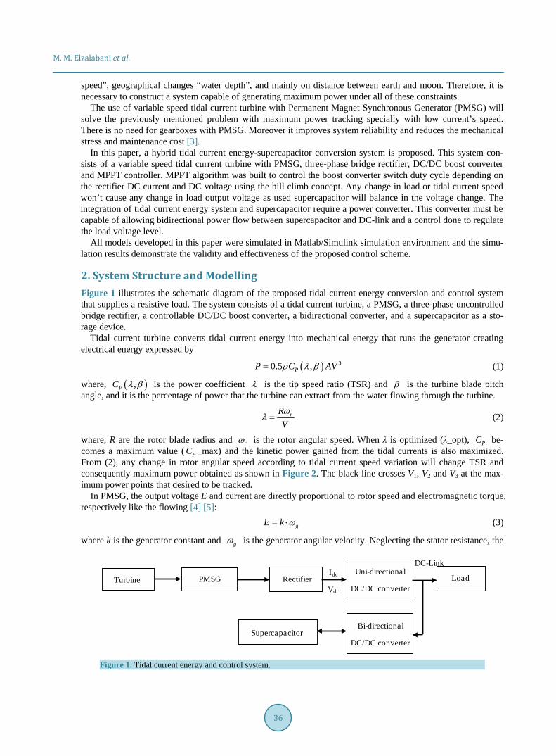
2. System Structure and Modelling Figure 1 illustrates the schematic diagram of the proposed tidal current energy conversion and control system that supplies a resistive load. The system consists of a tidal current turbine, a PMSG, a three-phase uncontrolled bridge rectifier, a controllable DC/DC boost converter, a bidirectional converter, and a supercapacitor as a sto-rage device.
Tidal current turbine converts tidal current energy into mechanical energy that runs the generator creating electrical energy expressed by
( ) 30.5 ,PP C AVρ λ β= (1)
where, ( ),PC λ β is the power coefficient λ is the tip speed ratio (TSR) and β is the turbine blade pitch angle, and it is the percentage of power that the turbine can extract from the water flowing through the turbine.
rRVω
λ = (2)
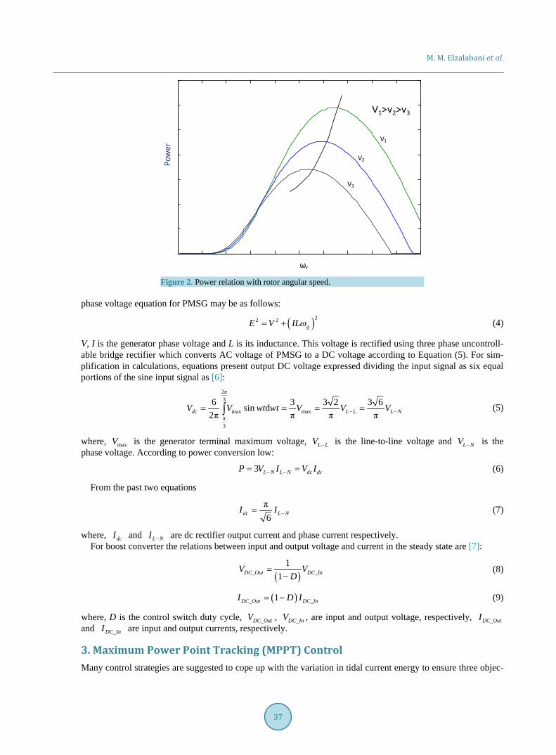
where, R are the rotor blade radius and rω is the rotor angular speed. When λ is optimized (λ_opt), PC be-comes a maximum value ( PC _max) and the kinetic power gained from the tidal currents is also maximized. From (2), any change in rotor angular speed according to tidal current speed variation will change TSR and consequently maximum power obtained as shown in Figure 2. The black line crosses V1, V2 and V3 at the max-imum power points that desired to be tracked.
In PMSG, the output voltage E and current are directly proportional to rotor speed and electromagnetic torque, respectively like the flowing [4] [5]:
gE k ω= ⋅ (3)
where k is the generator constant and gω is the generator angular velocity. Neglecting the stator resistance, the
Figure 1. Tidal current energy and control system.
Idc
Vdc
Turbine Rectifier LoadPMSGUni-directional
DC/DC converter
Bi-directional
DC/DC converterSupercapacitor
DC-Link
M. M. Elzalabani et al.
37
Figure 2. Power relation with rotor angular speed.
phase voltage equation for PMSG may be as follows:
( )22 2gE V ILω= + (4)
V, I is the generator phase voltage and L is its inductance. This voltage is rectified using three phase uncontroll-able bridge rectifier which converts AC voltage of PMSG to a DC voltage according to Equation (5). For sim-plification in calculations, equations present output DC voltage expressed dividing the input signal as six equal portions of the sine input signal as [6]:
2π3
max maxπ3
6 3 3 2 3 6sin d2π π π πdc L L L NV V wt wt V V V− −= = = =∫ (5)
where, maxV is the generator terminal maximum voltage, L LV − is the line-to-line voltage and L NV − is the phase voltage. According to power conversion low:
3 L N L N dc dcP V I V I− −= = (6)
From the past two equations
π6dc L NI I −= (7)
where, dcI and L NI − are dc rectifier output current and phase current respectively. For boost converter the relations between input and output voltage and current in the steady state are [7]:
( )_ _1
1DC Out DC InV VD
=−
(8)
( )_ _1DC Out DC InI D I= − (9)
where, D is the control switch duty cycle, _DC OutV , _DC InV , are input and output voltage, respectively, _DC OutI and _DC InI are input and output currents, respectively.
3. Maximum Power Point Tracking (MPPT) Control Many control strategies are suggested to cope up with the variation in tidal current energy to ensure three objec-
Pow
er
V1
V2
V3
V1>v2>v3
ωr
M. M. Elzalabani et al.
38
tives, 1) Energy capture: the overall efficiency of the rotor and transmission must be maximized to provide maximum possible power production; 2) Mechanical loads: guarantee a certain level of resilience of mechanical parts by lightening the variable loads; 3) Safety: safe turbine operation, mitigate damaging, fatigue loads and detect fault conditions.
Among those control strategies that are used in MPPT are the Tip Speed Ratio (TSR) algorithm, Power Signal Feedback (PSF) algorithm and Hill Climb Search (HCS) algorithm. Mechanical variables are feed to the con-troller in case of TSR control system and electrical ones used in PSF and HCS control algorithms. The Boost DC-DC converter importance appears at low generator speed (low current speed). Moreover, the total harmonic distortion decreases [8].
3.1. Hill Climb Search (HCS) The HCS control algorithm continuously searches for the peak output power of the tidal current turbine. It over- comes the previously mentioned TSR and PSF methods problems, as there is no need for tidal current speeds, rotor angular speed or system dynamic characteristics. This tracking algorithm taking into account the current operating point power and compare it with neighbor power points, if the new neighbor power point is greater than current operating point power, the controller will update the operating point to the new one and vice versa.
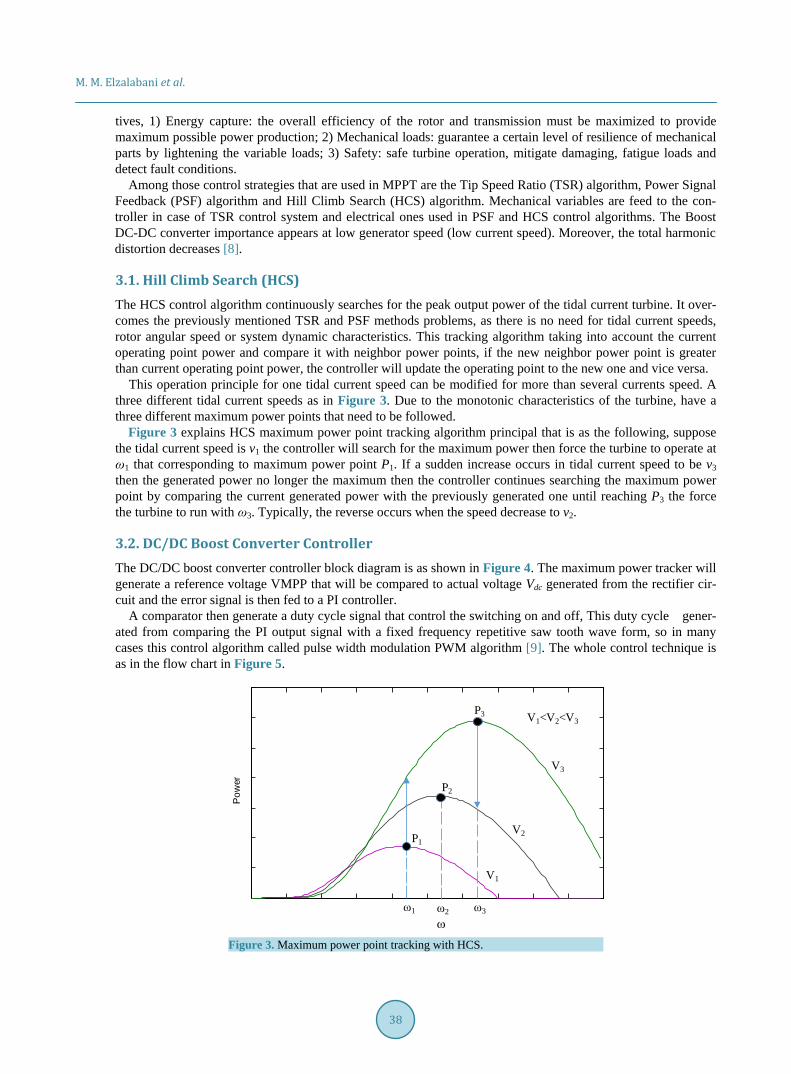
This operation principle for one tidal current speed can be modified for more than several currents speed. A three different tidal current speeds as in Figure 3. Due to the monotonic characteristics of the turbine, have a three different maximum power points that need to be followed.
Figure 3 explains HCS maximum power point tracking algorithm principal that is as the following, suppose the tidal current speed is v1 the controller will search for the maximum power then force the turbine to operate at ω1 that corresponding to maximum power point P1. If a sudden increase occurs in tidal current speed to be v3 then the generated power no longer the maximum then the controller continues searching the maximum power point by comparing the current generated power with the previously generated one until reaching P3 the force the turbine to run with ω3. Typically, the reverse occurs when the speed decrease to v2.
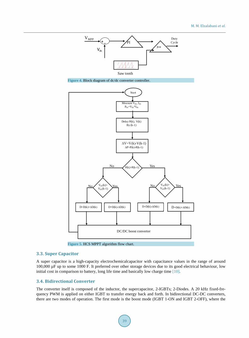
3.2. DC/DC Boost Converter Controller The DC/DC boost converter controller block diagram is as shown in Figure 4. The maximum power tracker will generate a reference voltage VMPP that will be compared to actual voltage Vdc generated from the rectifier cir-cuit and the error signal is then fed to a PI controller.
A comparator then generate a duty cycle signal that control the switching on and off, This duty cycle gener-ated from comparing the PI output signal with a fixed frequency repetitive saw tooth wave form, so in many cases this control algorithm called pulse width modulation PWM algorithm [9]. The whole control technique is as in the flow chart in Figure 5.
Figure 3. Maximum power point tracking with HCS.
ω3ω2ω1
ω
P1
P2
P3
Pow
er
V1
V2
V3
V1<V2<V3
M. M. Elzalabani et al.
39
Figure 4. Block diagram of dc/dc converter controller.
Figure 5. HCS MPPT algorithm flow chart.
3.3. Super Capacitor A super capacitor is a high-capacity electrochemicalcapacitor with capacitance values in the range of around 100,000 µF up to some 1000 F. It preferred over other storage devices due to its good electrical behaviour, low initial cost in comparison to battery, long life time and basically low charge time [10].
3.4. Bidirectional Converter The converter itself is composed of the inductor, the supercapacitor, 2-IGBTs; 2-Diodes. A 20 kHz fixed-fre- quency PWM is applied on either IGBT to transfer energy back and forth. In bidirectional DC-DC converters, there are two modes of operation. The first mode is the boost mode (IGBT 1-ON and IGBT 2-OFF), where the
Duty Cycle
VMPPPI
>=Vdc
+ -
Saw tooth
Delay P(k), V(k)By (k-1)
Measure Vdc, IdcPdc=Vdc*Idc
Start
∆V=V(k)-V(k-1)∆P=P(k)-P(k-1)
No YesP(k)>P(k-1)
YesNoNo Yes Vdc(k)>Vdc(k-1)
Vdc(k)>Vdc(k-1)
D=D(k)+∆D(k) D=D(k)-∆D(k) D=D(k)+∆D(k)D=D(k)-∆D(k)
DC/DC boost converter
M. M. Elzalabani et al.
40
supercapacitor is discharged to a higher voltage level at the DC link; in the second mode, buck mode (IGBT 1-OFF and IGBT 2-ON); here the excess power from the tidal current turbine charges supercapacitor [11].
To ensure converter operating in continuous conduction mood, inductor value must be higher than that calcu-lated from the following equations [12]:
( )12
dcboost
L
VL G
f i= ⋅ −
∆ (10)
( )212
dcbuck
L
VL G G
f i= ⋅ −
∆ (11)
where, dcV is the desired output voltage, f is the switching frequency, Li∆ is the maximum allowable inductor current and G is the control switch duty cycle.
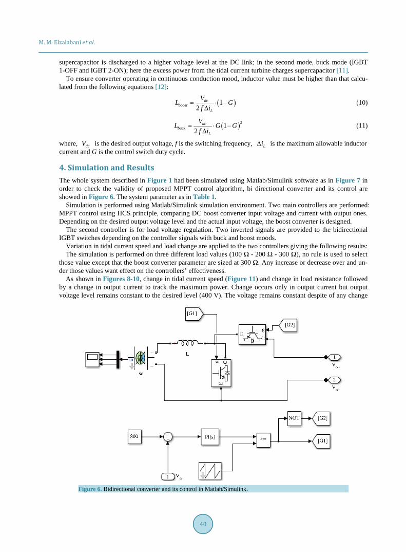
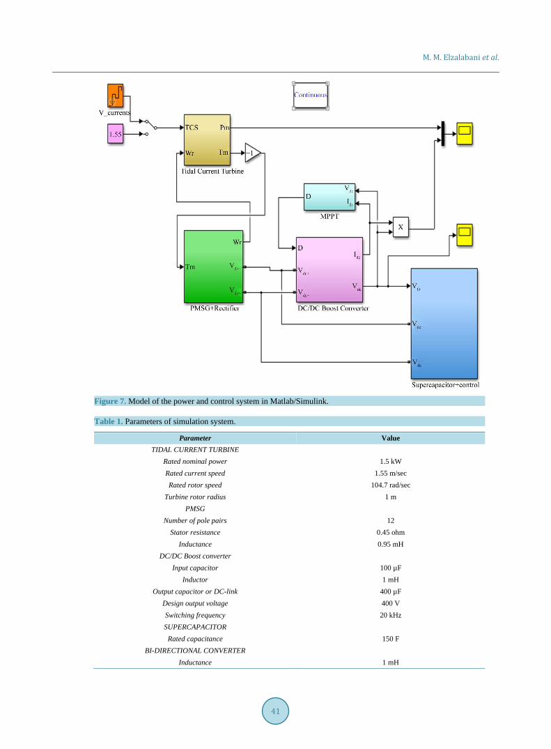
4. Simulation and Results The whole system described in Figure 1 had been simulated using Matlab/Simulink software as in Figure 7 in order to check the validity of proposed MPPT control algorithm, bi directional converter and its control are showed in Figure 6. The system parameter as in Table 1.
Simulation is performed using Matlab/Simulink simulation environment. Two main controllers are performed: MPPT control using HCS principle, comparing DC boost converter input voltage and current with output ones. Depending on the desired output voltage level and the actual input voltage, the boost converter is designed.
The second controller is for load voltage regulation. Two inverted signals are provided to the bidirectional IGBT switches depending on the controller signals with buck and boost moods.
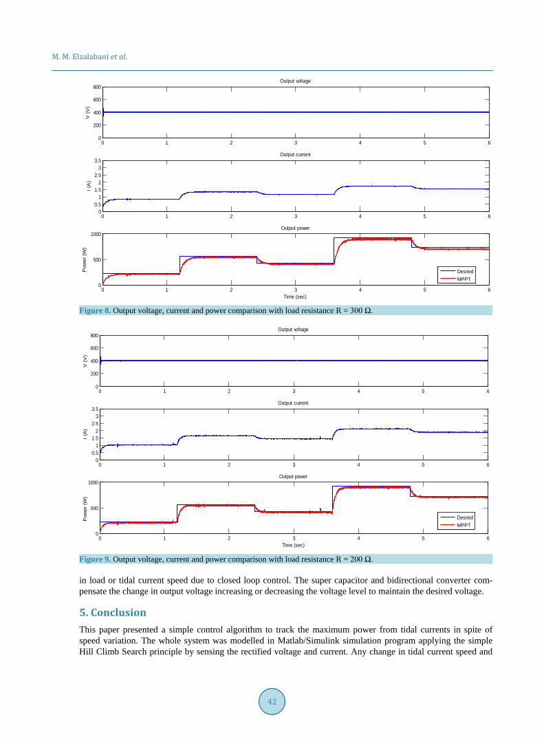
Variation in tidal current speed and load change are applied to the two controllers giving the following results: The simulation is performed on three different load values (100 Ω - 200 Ω - 300 Ω), no rule is used to select
those value except that the boost converter parameter are sized at 300 Ω. Any increase or decrease over and un-der those values want effect on the controllers’ effectiveness.
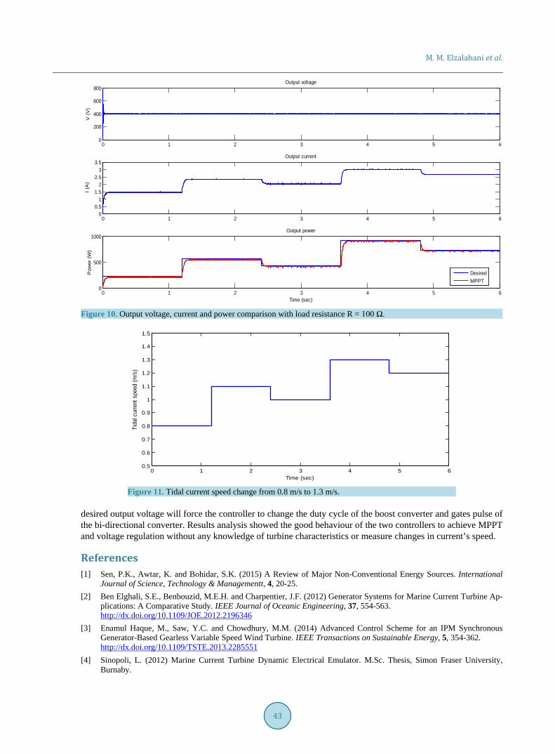
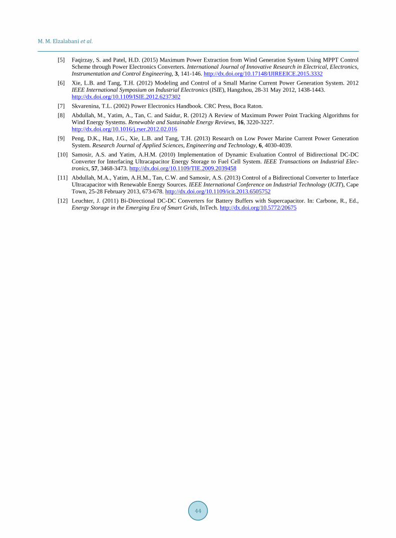
As shown in Figures 8-10, change in tidal current speed (Figure 11) and change in load resistance followed by a change in output current to track the maximum power. Change occurs only in output current but output voltage level remains constant to the desired level (400 V). The voltage remains constant despite of any change
Figure 6. Bidirectional converter and its control in Matlab/Simulink.
M. M. Elzalabani et al.
41
Figure 7. Model of the power and control system in Matlab/Simulink.
Table 1. Parameters of simulation system.
Parameter Value TIDAL CURRENT TURBINE
Rated nominal power 1.5 kW Rated current speed 1.55 m/sec Rated rotor speed 104.7 rad/sec
Turbine rotor radius 1 m PMSG
Number of pole pairs 12 Stator resistance 0.45 ohm
Inductance 0.95 mH DC/DC Boost converter
Input capacitor 100 µF Inductor 1 mH
Output capacitor or DC-link 400 µF Design output voltage 400 V Switching frequency 20 kHz SUPERCAPACITOR
Rated capacitance 150 F BI-DIRECTIONAL CONVERTER
Inductance 1 mH
M. M. Elzalabani et al.
42
Figure 8. Output voltage, current and power comparison with load resistance R = 300 Ω.
Figure 9. Output voltage, current and power comparison with load resistance R = 200 Ω. in load or tidal current speed due to closed loop control. The super capacitor and bidirectional converter com-pensate the change in output voltage increasing or decreasing the voltage level to maintain the desired voltage.
5. Conclusion This paper presented a simple control algorithm to track the maximum power from tidal currents in spite of speed variation. The whole system was modelled in Matlab/Simulink simulation program applying the simple Hill Climb Search principle by sensing the rectified voltage and current. Any change in tidal current speed and
0 1 2 3 4 5 60
200
400
600
800V
(V
)Output voltage
0 1 2 3 4 5 60
500
1000
Time (sec)
Pow
er (
W)
Output power
0 1 2 3 4 5 60
0.51
1.52
2.53
3.5
I (A
)
Output current
DesiredMPPT
0 1 2 3 4 5 60
200
400
600
800
V (
V)
Output voltage
0 1 2 3 4 5 60
0.51
1.52
2.53
3.5
I (A
)
Output current
0 1 2 3 4 5 60
500
1000
Time (sec)
Pow
er (
W)
Output power
DesiredMPPT
M. M. Elzalabani et al.
43
Figure 10. Output voltage, current and power comparison with load resistance R = 100 Ω.
Figure 11. Tidal current speed change from 0.8 m/s to 1.3 m/s.
desired output voltage will force the controller to change the duty cycle of the boost converter and gates pulse of the bi-directional converter. Results analysis showed the good behaviour of the two controllers to achieve MPPT and voltage regulation without any knowledge of turbine characteristics or measure changes in current’s speed.
References [1] Sen, P.K., Awtar, K. and Bohidar, S.K. (2015) A Review of Major Non-Conventional Energy Sources. International
Journal of Science, Technology & Managementt, 4, 20-25. [2] Ben Elghali, S.E., Benbouzid, M.E.H. and Charpentier, J.F. (2012) Generator Systems for Marine Current Turbine Ap-
plications: A Comparative Study. IEEE Journal of Oceanic Engineering, 37, 554-563. http://dx.doi.org/10.1109/JOE.2012.2196346
[3] Enamul Haque, M., Saw, Y.C. and Chowdhury, M.M. (2014) Advanced Control Scheme for an IPM Synchronous Generator-Based Gearless Variable Speed Wind Turbine. IEEE Transactions on Sustainable Energy, 5, 354-362. http://dx.doi.org/10.1109/TSTE.2013.2285551
[4] Sinopoli, L. (2012) Marine Current Turbine Dynamic Electrical Emulator. M.Sc. Thesis, Simon Fraser University, Burnaby.
0 1 2 3 4 5 60
200
400
600
800V
(V
)Output voltage
0 1 2 3 4 5 60
0.51
1.52
2.53
3.5
I (A
)
Output current
0 1 2 3 4 5 60
500
1000
Time (sec)
Pow
er (
W)
Output power
DesiredMPPT
0 1 2 3 4 5 60.5
0.6
0.7
0.8
0.9
1
1.1
1.2
1.3
1.4
1.5
Time (sec)
Tida
l cur
rent
spe
ed (m
/s)
M. M. Elzalabani et al.
44
[5] Faqirzay, S. and Patel, H.D. (2015) Maximum Power Extraction from Wind Generation System Using MPPT Control Scheme through Power Electronics Converters. International Journal of Innovative Research in Electrical, Electronics, Instrumentation and Control Engineering, 3, 141-146. http://dx.doi.org/10.17148/IJIREEICE.2015.3332
[6] Xie, L.B. and Tang, T.H. (2012) Modeling and Control of a Small Marine Current Power Generation System. 2012 IEEE International Symposium on Industrial Electronics (ISIE), Hangzhou, 28-31 May 2012, 1438-1443. http://dx.doi.org/10.1109/ISIE.2012.6237302
[7] Skvarenina, T.L. (2002) Power Electronics Handbook. CRC Press, Boca Raton. [8] Abdullah, M., Yatim, A., Tan, C. and Saidur, R. (2012) A Review of Maximum Power Point Tracking Algorithms for
Wind Energy Systems. Renewable and Sustainable Energy Reviews, 16, 3220-3227. http://dx.doi.org/10.1016/j.rser.2012.02.016
[9] Peng, D.K., Han, J.G., Xie, L.B. and Tang, T.H. (2013) Research on Low Power Marine Current Power Generation System. Research Journal of Applied Sciences, Engineering and Technology, 6, 4030-4039.
[10] Samosir, A.S. and Yatim, A.H.M. (2010) Implementation of Dynamic Evaluation Control of Bidirectional DC-DC Converter for Interfacing Ultracapacitor Energy Storage to Fuel Cell System. IEEE Transactions on Industrial Elec-tronics, 57, 3468-3473. http://dx.doi.org/10.1109/TIE.2009.2039458
[11] Abdullah, M.A., Yatim, A.H.M., Tan, C.W. and Samosir, A.S. (2013) Control of a Bidirectional Converter to Interface Ultracapacitor with Renewable Energy Sources. IEEE International Conference on Industrial Technology (ICIT), Cape Town, 25-28 February 2013, 673-678. http://dx.doi.org/10.1109/icit.2013.6505752
[12] Leuchter, J. (2011) Bi-Directional DC-DC Converters for Battery Buffers with Supercapacitor. In: Carbone, R., Ed., Energy Storage in the Emerging Era of Smart Grids, InTech. http://dx.doi.org/10.5772/20675