Iterative learning control - Fermilab
22
Iterative learning control (Study of work by Christian Schmidt and others) M.Musienko, USPAS 2017
Transcript of Iterative learning control - Fermilab
Iterative learning control (Study of work by Christian Schmidt and
others)
M.Musienko, USPAS 2017
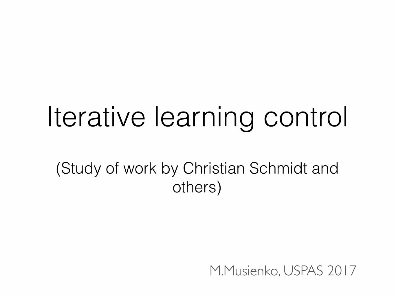
Free Electron Laser in Hamburg (FLASH) at DESY
• pulsed RF Operation due to the thermal losses
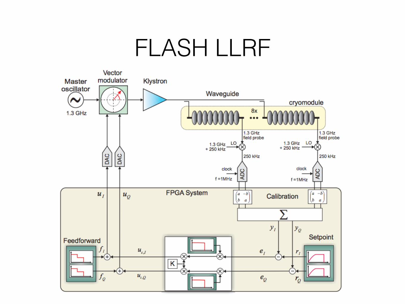
FLASH LLRF
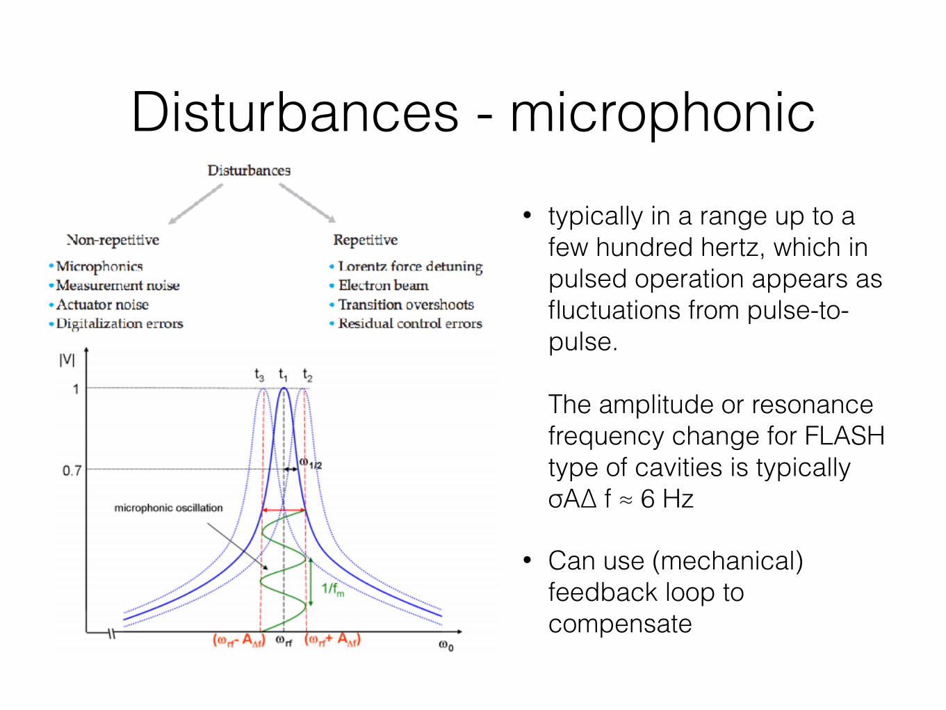
Disturbances - microphonic• typically in a range up to a
few hundred hertz, which in pulsed operation appears as fluctuations from pulse-to-pulse.The amplitude or resonance frequency change for FLASH type of cavities is typically σA∆ f ≈ 6 Hz
• Can use (mechanical) feedback loop to compensate
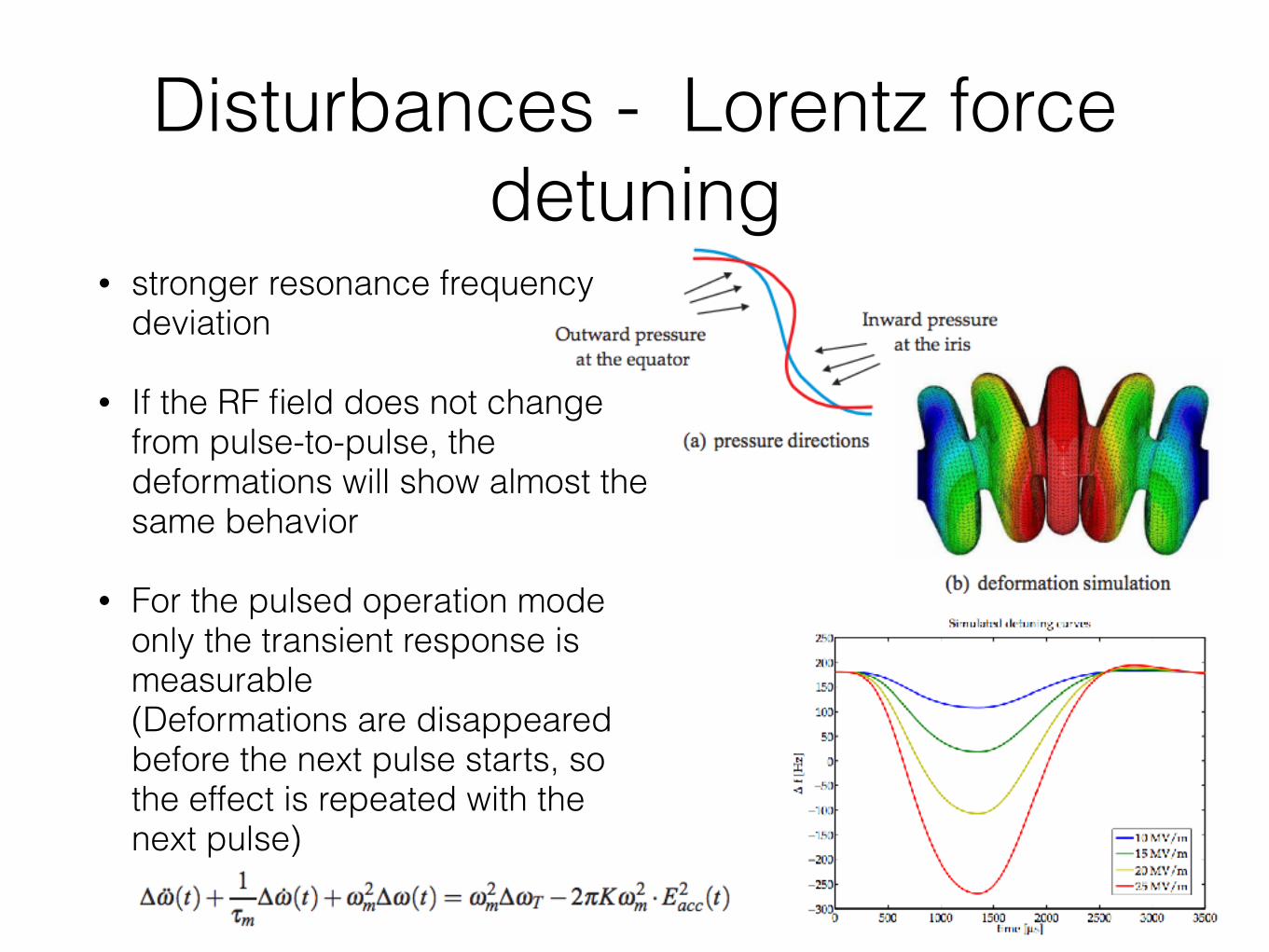
Disturbances - Lorentz force detuning
• stronger resonance frequency deviation
• If the RF field does not change from pulse-to-pulse, the deformations will show almost the same behavior
• For the pulsed operation mode only the transient response is measurable (Deformations are disappeared before the next pulse starts, so the effect is repeated with the next pulse)
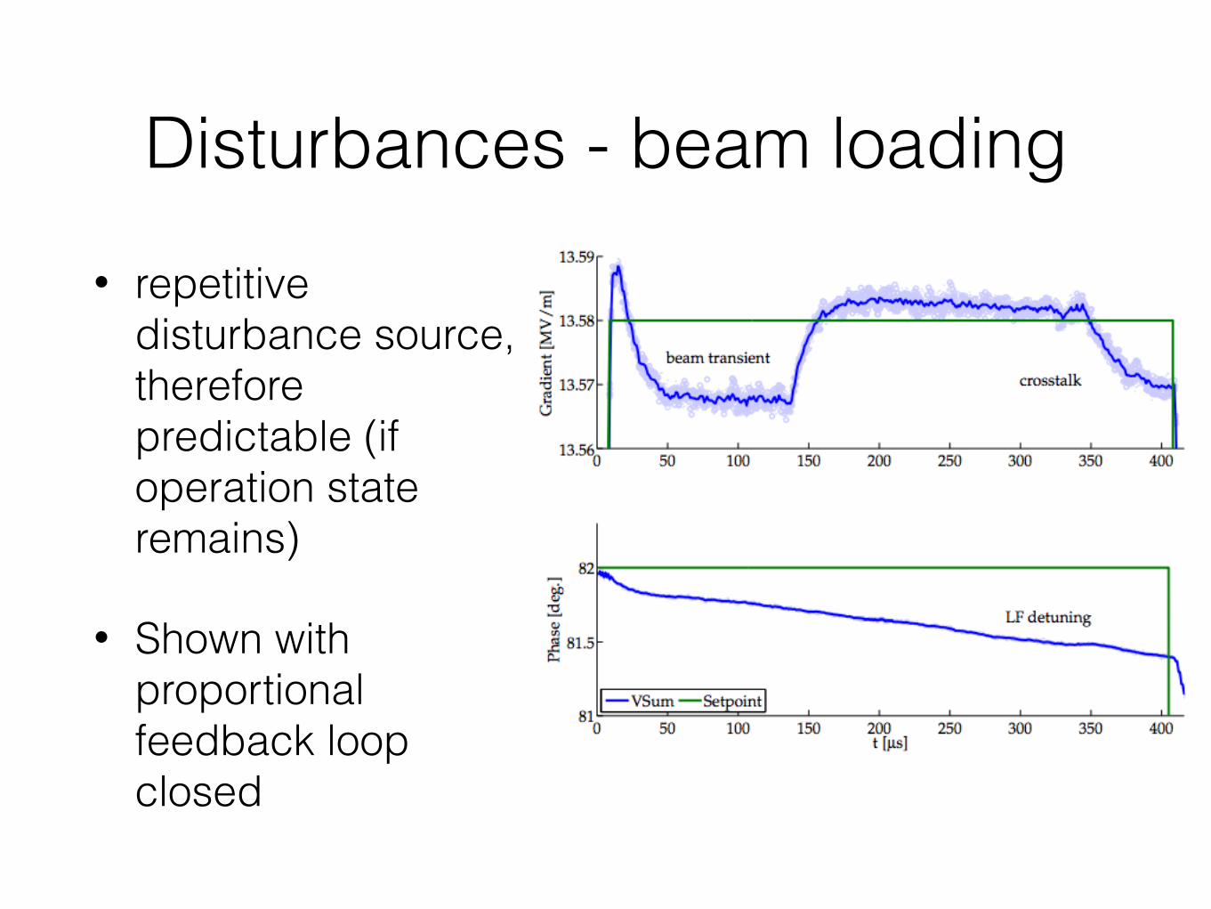
Disturbances - beam loading• repetitive
disturbance source, therefore predictable (if operation state remains)
• Shown with proportional feedback loop closed
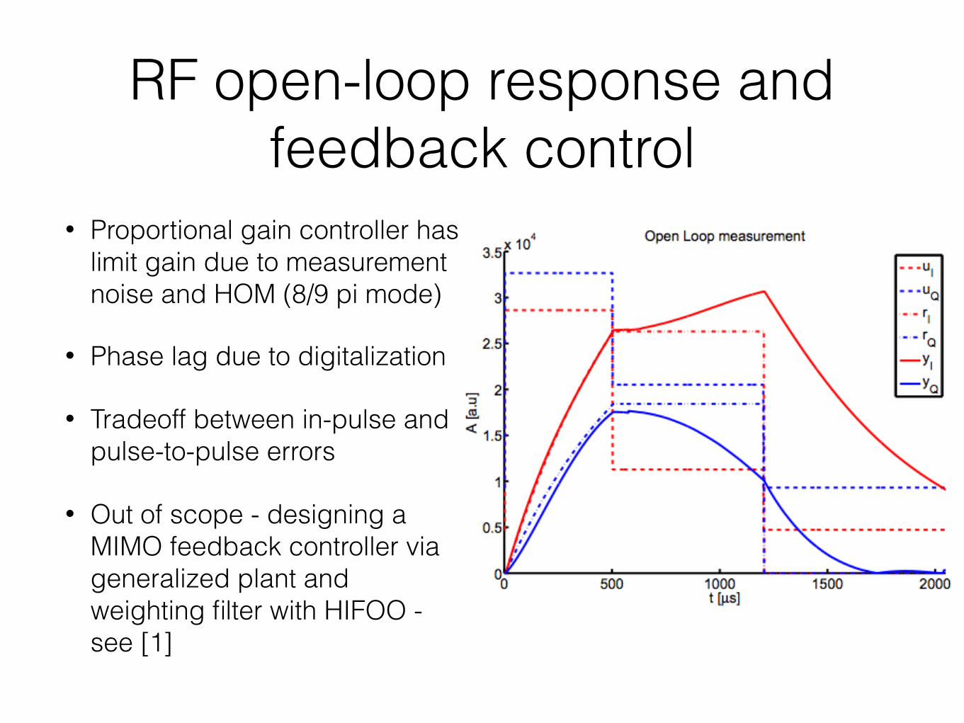
RF open-loop response and feedback control
• Proportional gain controller has limit gain due to measurement noise and HOM (8/9 pi mode)
• Phase lag due to digitalization
• Tradeoff between in-pulse and pulse-to-pulse errors
• Out of scope - designing a MIMO feedback controller via generalized plant and weighting filter with HIFOO - see [1]
Feedforward control
• Residual field errors due to the low BW of the feedback loop and limitations on the gain
• Predictable disturbance - can compensate with RF modulation
• How to calculate? Constant during operation? Optimal? Iterative learning control - take information from previous trials to optimize the control inputs on the next trial
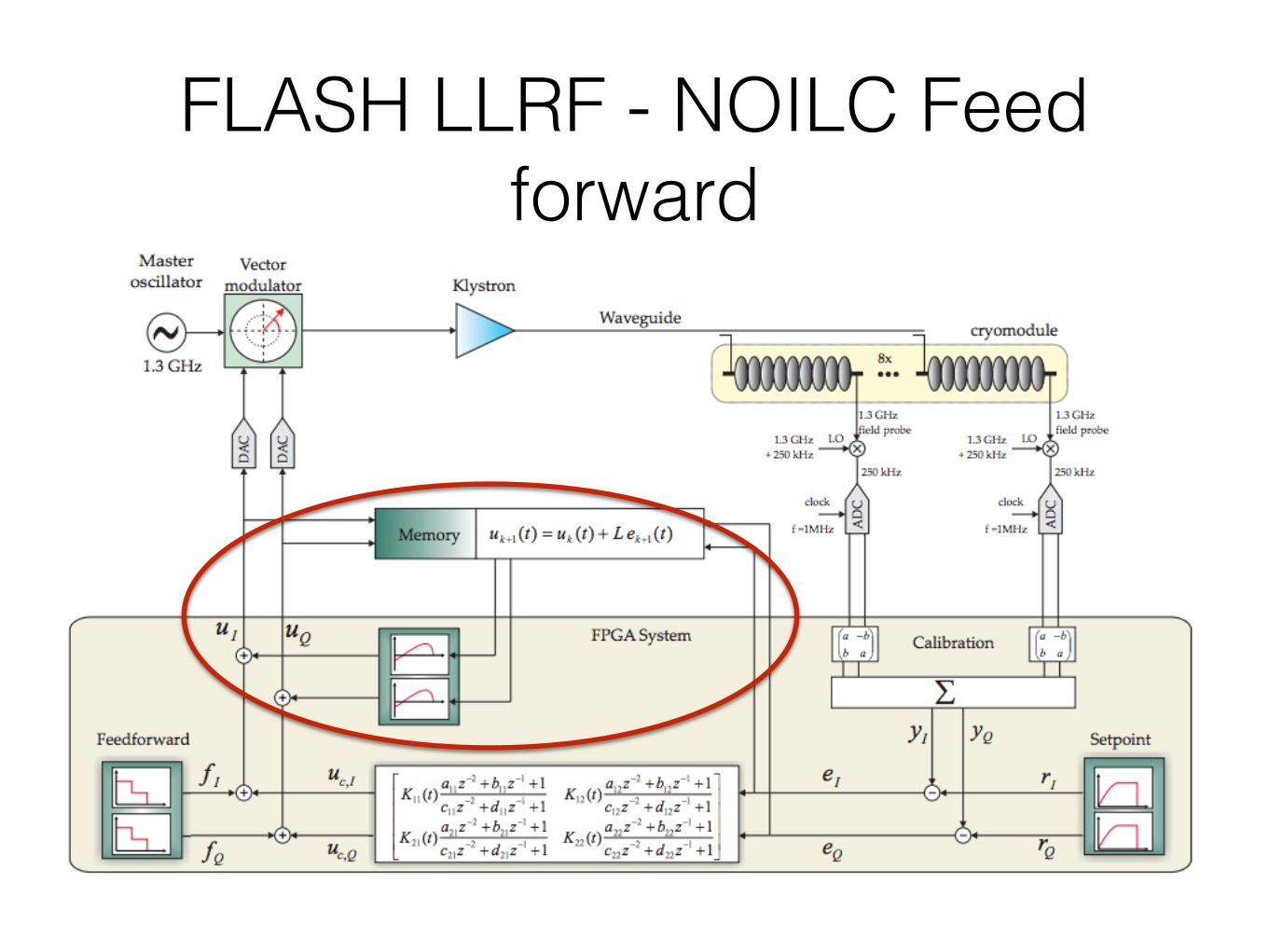
FLASH LLRF - NOILC Feed forward
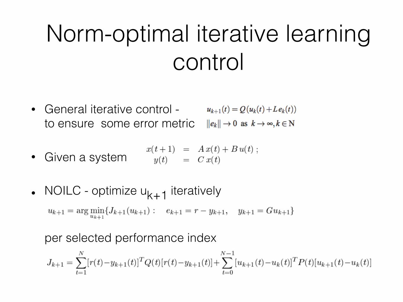
Norm-optimal iterative learning control
• General iterative control - to ensure some error metric
• Given a system
• NOILC - optimize uk+1 iteratively per selected performance index
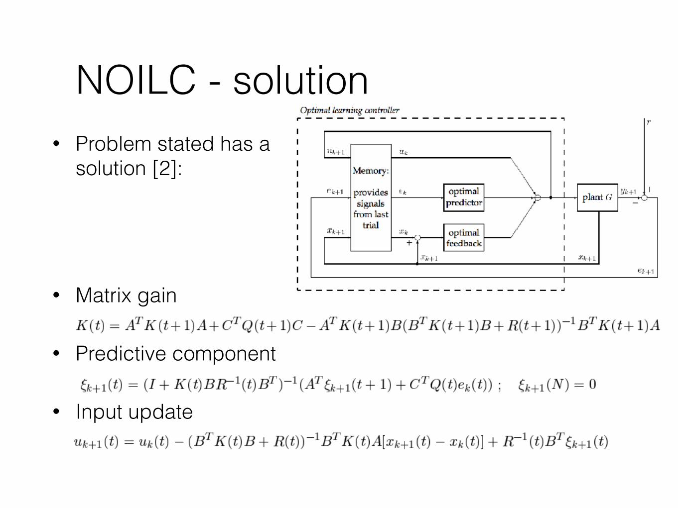
NOILC - solution• Problem stated has a
solution [2]:
• Matrix gain
• Predictive component
• Input update
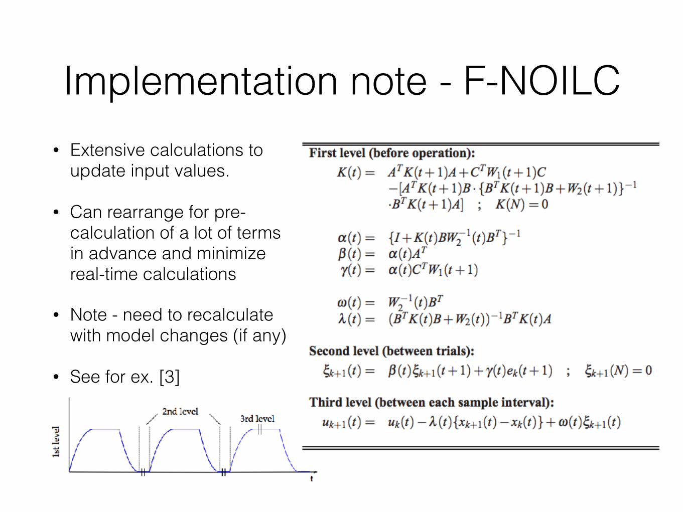
Implementation note - F-NOILC• Extensive calculations to
update input values.
• Can rearrange for pre-calculation of a lot of terms in advance and minimize real-time calculations
• Note - need to recalculate with model changes (if any)
• See for ex. [3]
Out of scope - system identification
• Requires A, B, C, D…
• Black-box model for system identification
• Model validation
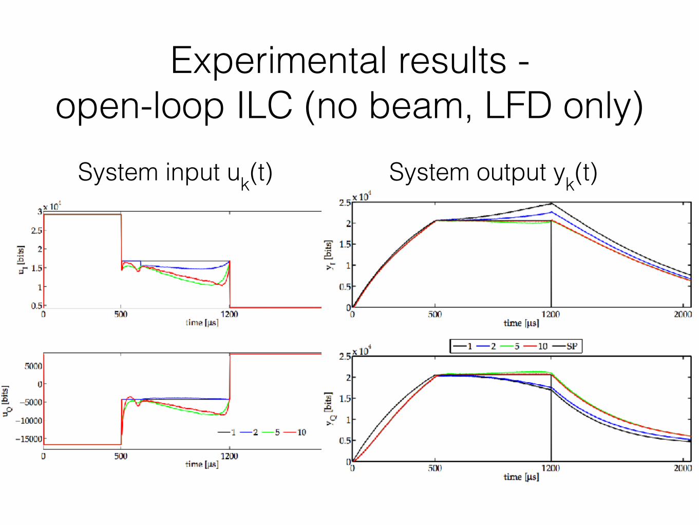
Experimental results - open-loop ILC (no beam, LFD only)
System input uk(t) System output yk(t)
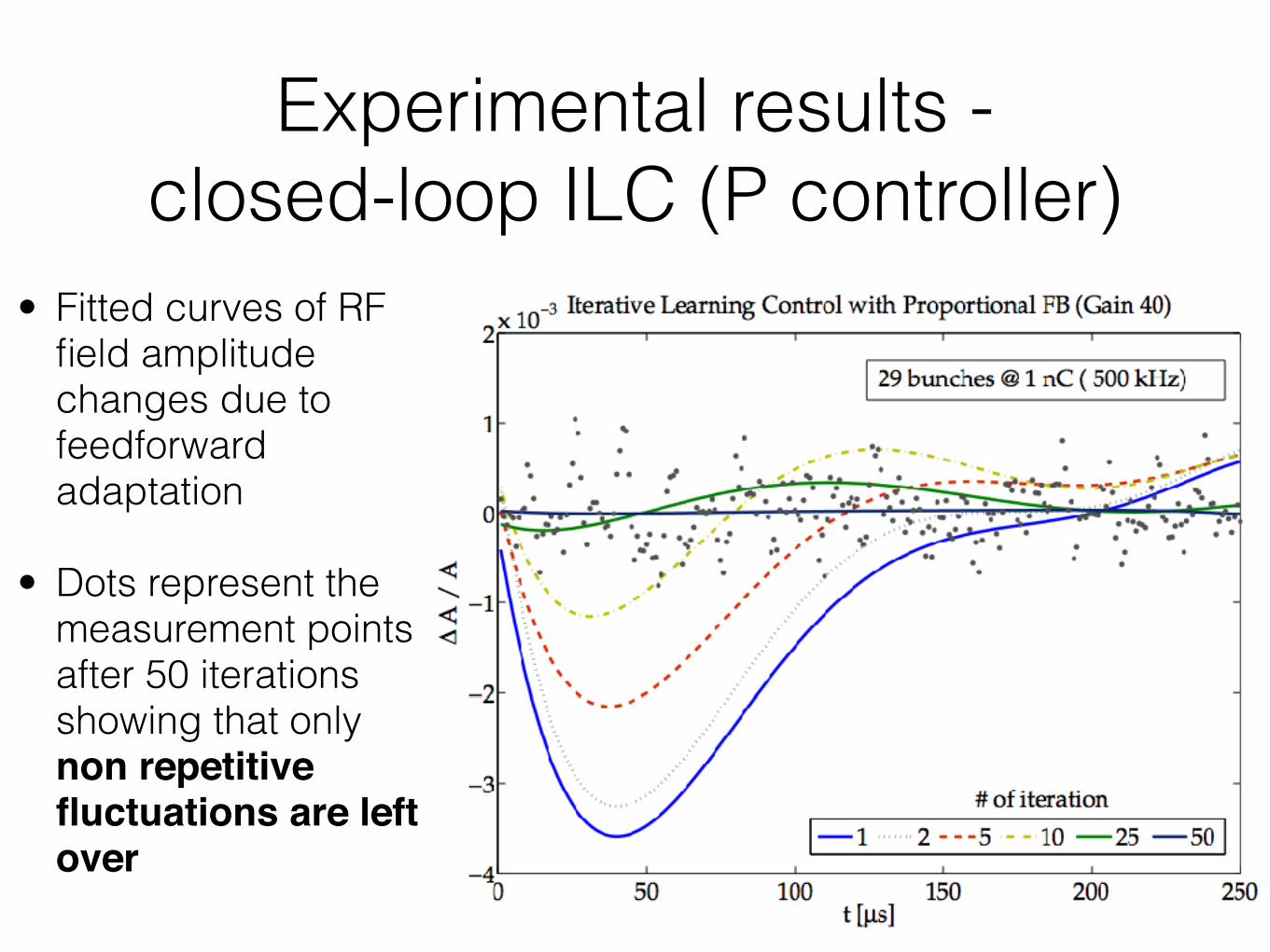
Experimental results - closed-loop ILC (P controller)
• Fitted curves of RF field amplitude changes due to feedforward adaptation
• Dots represent the measurement points after 50 iterations showing that only non repetitive fluctuations are left over
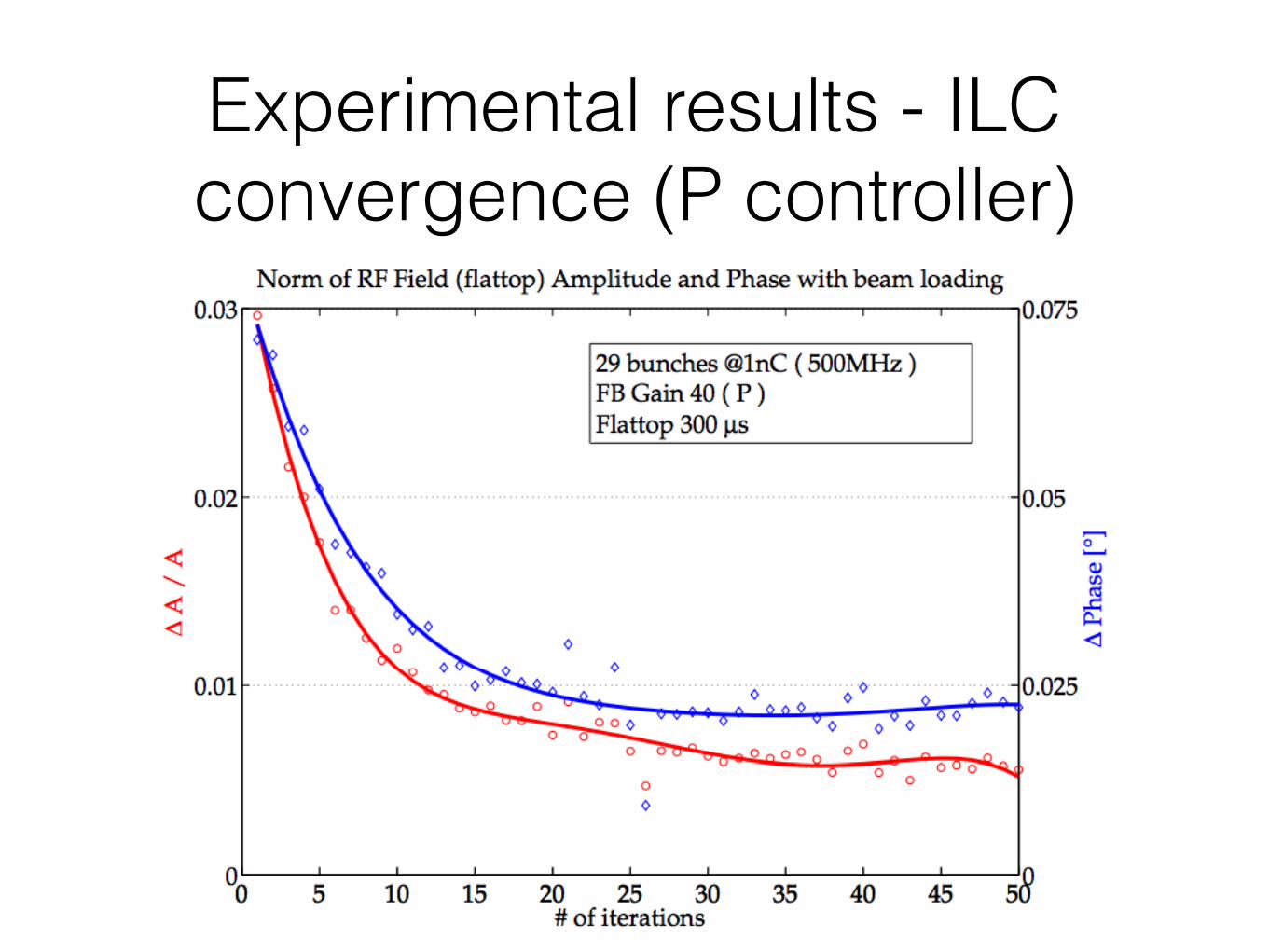
Experimental results - ILC convergence (P controller)
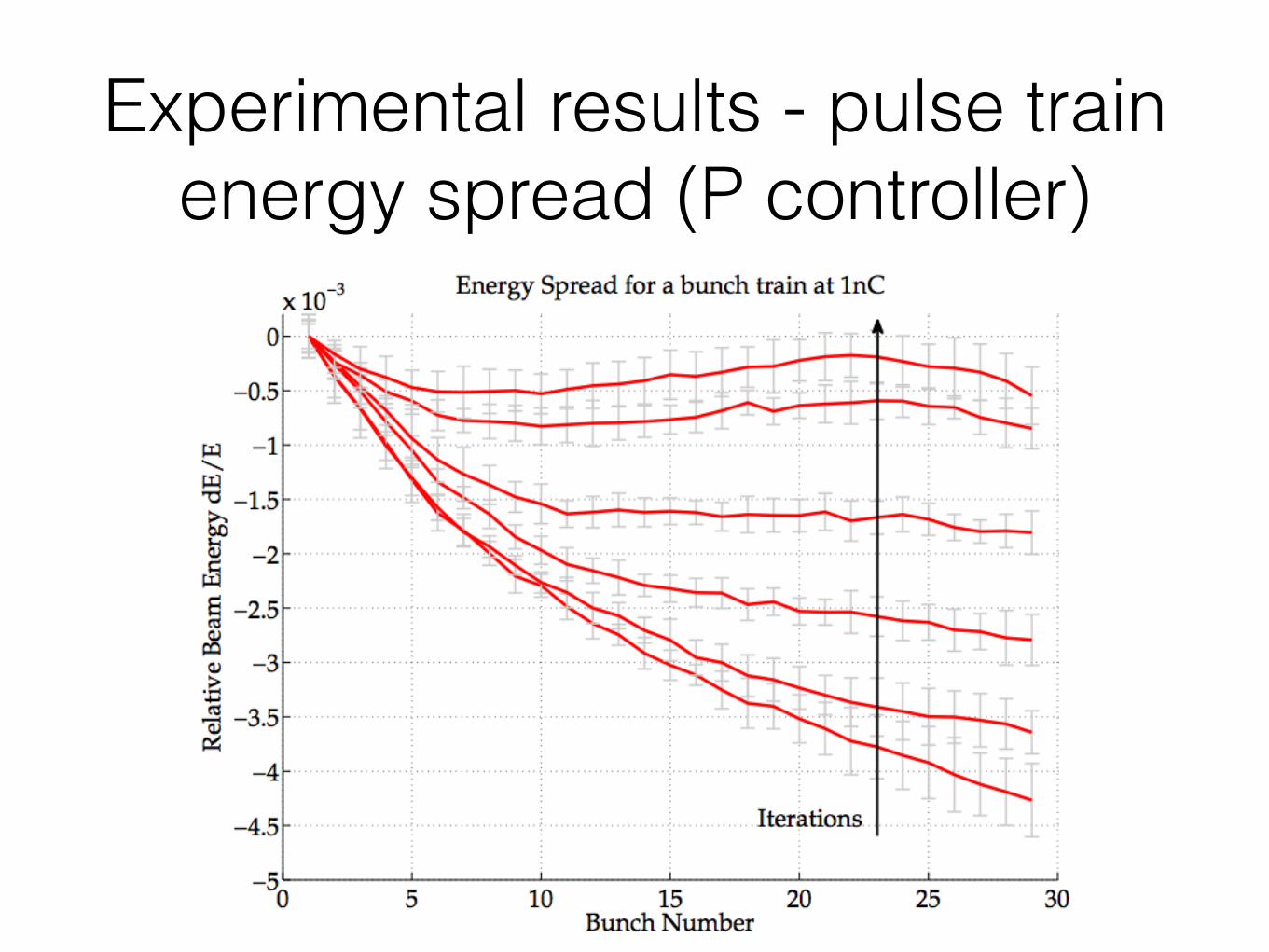
Experimental results - pulse train energy spread (P controller)
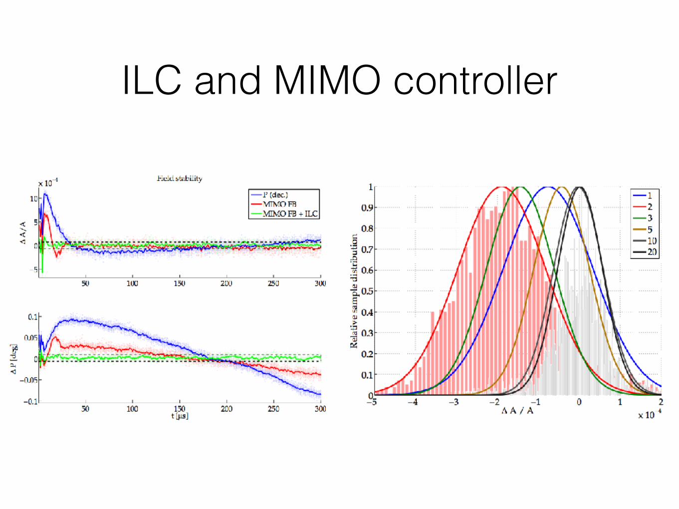
ILC and MIMO controller
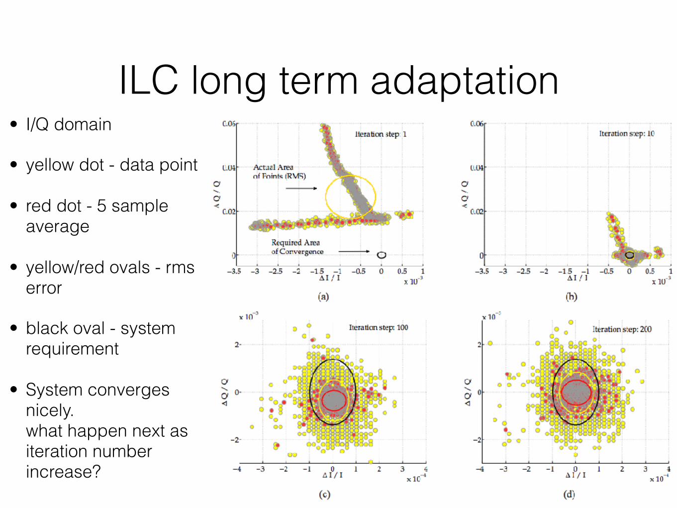
ILC long term adaptation• I/Q domain
• yellow dot - data point
• red dot - 5 sample average
• yellow/red ovals - rms error
• black oval - system requirement
• System converges nicely. what happen next as iteration number increase?
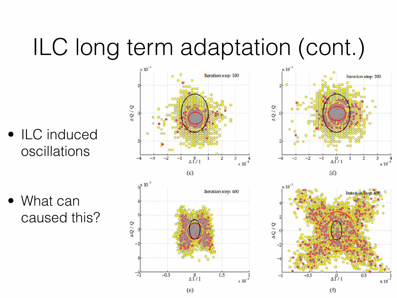
ILC long term adaptation (cont.)
• ILC induced oscillations
• What can caused this?
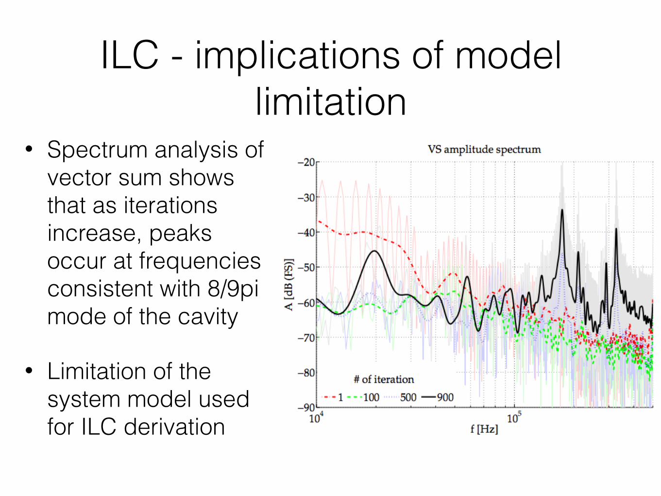
ILC - implications of model limitation
• Spectrum analysis of vector sum shows that as iterations increase, peaks occur at frequencies consistent with 8/9pi mode of the cavity
• Limitation of the system model used for ILC derivation
ReferencesFollowing references were used in this presentation for strictly educational purpose:
[1] C. Schmidt (2010): RF System Modeling and Controller Design for the European XFEL (Doctoral thesis)
[2] N. Amann, D.H. Owens, E. Rogers: Iterative learning control for discrete-time systems with exponential rate of convergence, IEE Proc. Control Theory Appl., vol. 143, no. 2, pp. 217224, 1996.
[3] J.D. Ratcliffe, P.L. Lewin, E. Rogers, J.J. Htnen, D.H. Owens: Norm-Optimal Iterative Learning Control Applied to Gantry Robots for Automation Applications, IEEE Transactions on Robotics, Vol. 22,No. 6, 2006