Insert 150420130854-conversion-gate01
24
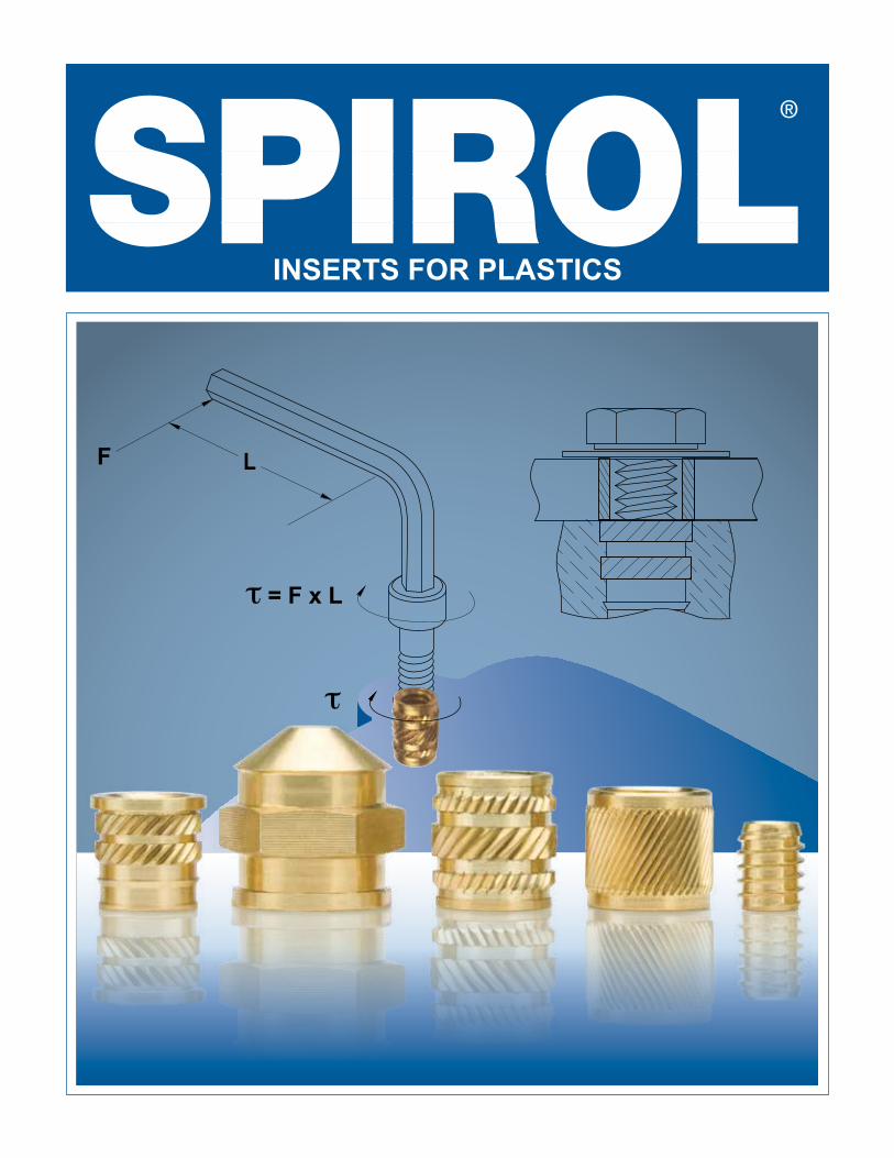
L F τ = F x L τ INSERTS FOR PLASTICS
-
Upload
laxmanrsingh -
Category
Automotive
-
view
19 -
download
1
Transcript of Insert 150420130854-conversion-gate01
Cover1
LF
τ = F x L
τ
INSERTS FOR PLASTICS
Cover2
Plastic
Insert
Bolt
Friction Force
Force L
TorqueF x L
Axial Load(Tension)
Torque
μ = Coefficient of Friction ≈ 0.2
Tension =Torque
μ x Bolt ø
WHY INSERTS?
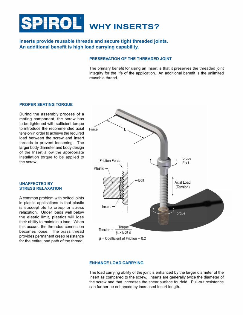
Inserts provide reusable threads and secure tight threaded joints.An additional benefit is high load carrying capability.
ENHANCE LOAD CARRYING
The load carrying ability of the joint is enhanced by the larger diameter of the Insert as compared to the screw. Inserts are generally twice the diameter of the screw and that increases the shear surface fourfold. Pull-out resistance can further be enhanced by increased Insert length.
UNAFFECTED BYSTRESS RELAXATION
A common problem with bolted joints in plastic applications is that plastic is susceptible to creep or stress relaxation. Under loads well below the elastic limit, plastics will lose their ability to maintain a load. When this occurs, the threaded connection becomes loose. The brass thread provides permanent creep resistance for the entire load path of the thread.
PRESERVATION OF THE THREADED JOINT
The primary benefit for using an Insert is that it preserves the threaded joint integrity for the life of the application. An additional benefit is the unlimited reusable thread.
PROPER SEATING TORQUE
During the assembly process of a mating component, the screw has to be tightened with sufficient torque to introduce the recommended axial tension in order to achieve the required load between the screw and Insert threads to prevent loosening. The larger body diameter and body design of the Insert allow the appropriate installation torque to be applied to the screw.
1
TECHNICAL SUPPORT
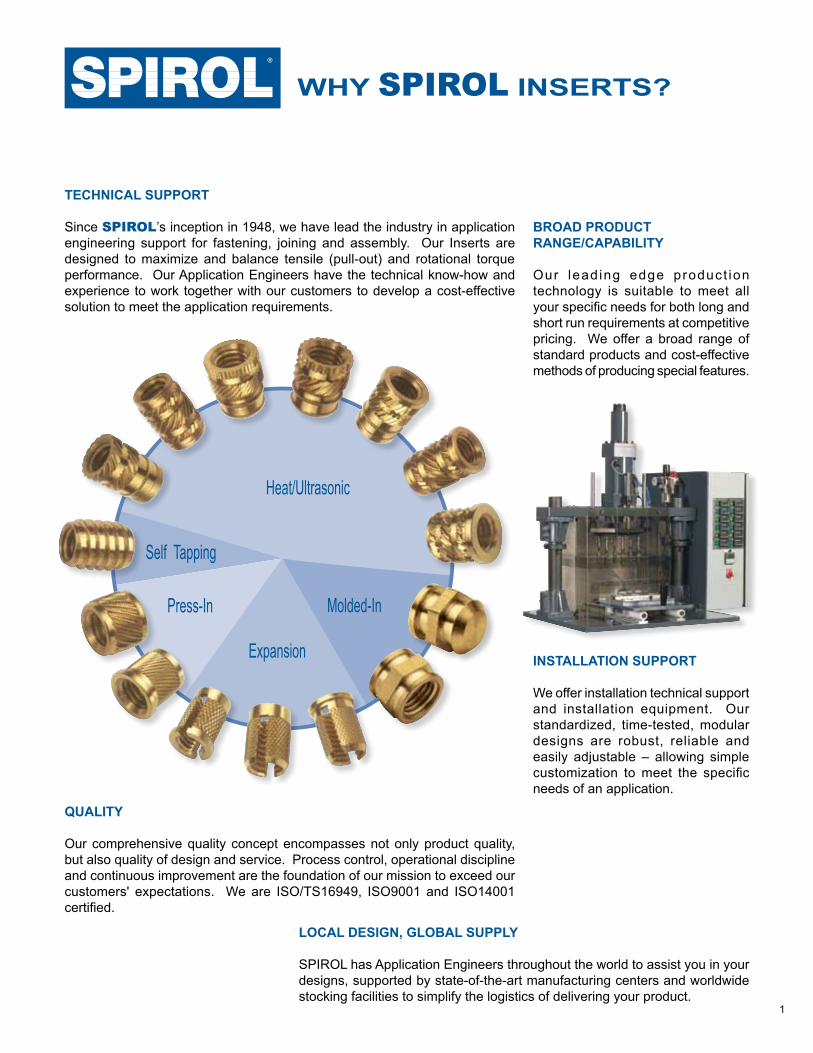
Since SPIROL’s inception in 1948, we have lead the industry in application engineering support for fastening, joining and assembly. Our Inserts are designed to maximize and balance tensile (pull-out) and rotational torque performance. Our Application Engineers have the technical know-how and experience to work together with our customers to develop a cost-effective solution to meet the application requirements.
BROAD PRODUCTRANGE/CAPABILITY
Our lead ing edge product ion technology is suitable to meet all your specific needs for both long and short run requirements at competitive pricing. We offer a broad range of standard products and cost-effective methods of producing special features.
QUALITY
Our comprehensive quality concept encompasses not only product quality, but also quality of design and service. Process control, operational discipline and continuous improvement are the foundation of our mission to exceed our customers' expectations. We are ISO/TS16949, ISO9001 and ISO14001 certified.
INSTALLATION SUPPORT
We offer installation technical support and installation equipment. Our standardized, time-tested, modular designs are robust, reliable and easily adjustable – allowing simple customization to meet the specific needs of an application.
WHY SPIROL INSERTS?
Heat/Ultrasonic
Expansion
Press-In Molded-In
Self Tapping
LOCAL DESIGN, GLOBAL SUPPLY
SPIROL has Application Engineers throughout the world to assist you in your designs, supported by state-of-the-art manufacturing centers and worldwide stocking facilities to simplify the logistics of delivering your product.
2
Self-Tapping Inserts provide the best pull-out resistance for a post-mold installed Insert. The threads are designed with a thin profile to minimize inducing stress into the plastic and a relative coarse pitch to provide the maximum plastic shear surface to resist pull-out.
Installation torque is not a problem in that tightening increases the friction between the plastic and threads, and the larger diameter of the external Insert thread increases the frictional surface. Back-out torque performance relies totally on the greater surface area of the external Insert thread and the tension between the threads and plastic.
Again, to facilitate installation square to the hole, a good pilot is essential.
INSERT DESIGN
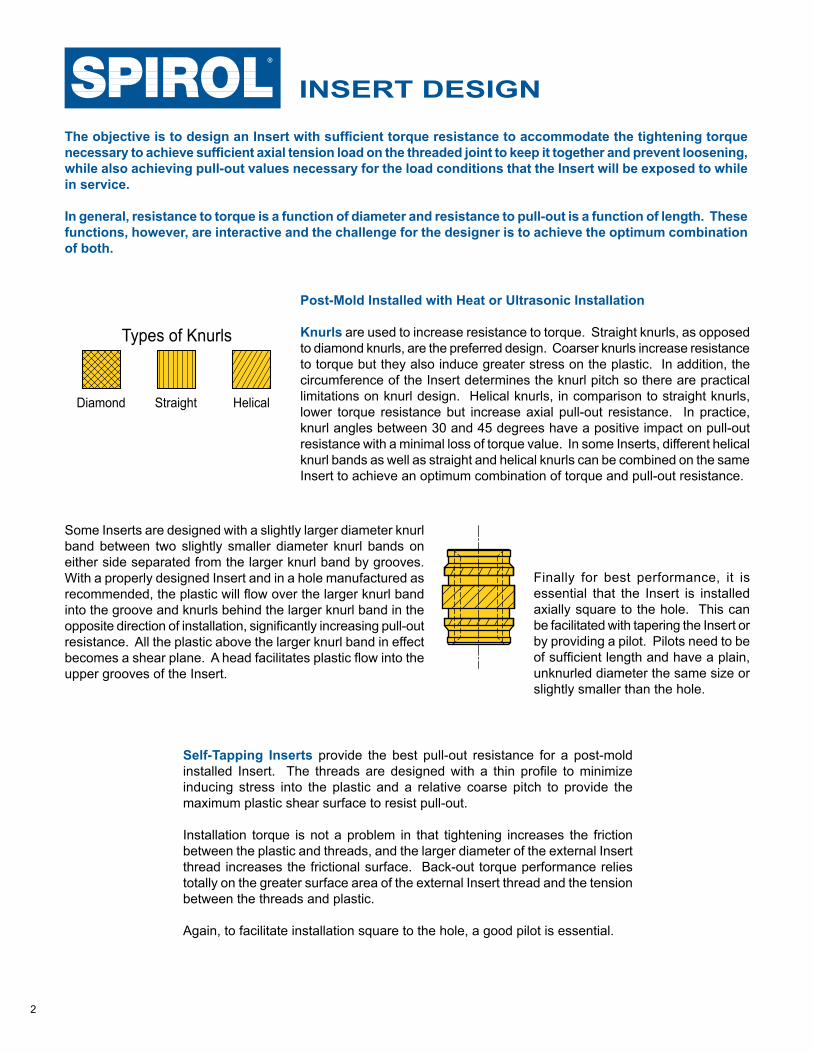
Diamond Straight Helical
Types of Knurls
Post-Mold Installed with Heat or Ultrasonic Installation
Knurls are used to increase resistance to torque. Straight knurls, as opposed to diamond knurls, are the preferred design. Coarser knurls increase resistance to torque but they also induce greater stress on the plastic. In addition, the circumference of the Insert determines the knurl pitch so there are practical limitations on knurl design. Helical knurls, in comparison to straight knurls, lower torque resistance but increase axial pull-out resistance. In practice, knurl angles between 30 and 45 degrees have a positive impact on pull-out resistance with a minimal loss of torque value. In some Inserts, different helical knurl bands as well as straight and helical knurls can be combined on the same Insert to achieve an optimum combination of torque and pull-out resistance.
The objective is to design an Insert with sufficient torque resistance to accommodate the tightening torque necessary to achieve sufficient axial tension load on the threaded joint to keep it together and prevent loosening, while also achieving pull-out values necessary for the load conditions that the Insert will be exposed to while in service.
In general, resistance to torque is a function of diameter and resistance to pull-out is a function of length. These functions, however, are interactive and the challenge for the designer is to achieve the optimum combination of both.
Some Inserts are designed with a slightly larger diameter knurl band between two slightly smaller diameter knurl bands on either side separated from the larger knurl band by grooves. With a properly designed Insert and in a hole manufactured as recommended, the plastic will flow over the larger knurl band into the groove and knurls behind the larger knurl band in the opposite direction of installation, significantly increasing pull-out resistance. All the plastic above the larger knurl band in effect becomes a shear plane. A head facilitates plastic flow into the upper grooves of the Insert.
Finally for best performance, it is essential that the Insert is installed axially square to the hole. This can be facilitated with tapering the Insert or by providing a pilot. Pilots need to be of sufficient length and have a plain, unknurled diameter the same size or slightly smaller than the hole.
3
2 Full ThreadsMinimum
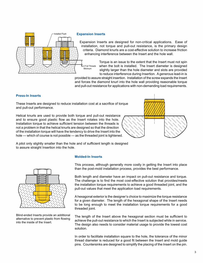
Installed Flush Expansion Inserts
Expansion Inserts are designed for non-critical applications. Ease of installation, not torque and pull-out resistance, is the primary design criteria. Diamond knurls are a cost-effective solution to increase friction enhancing interference between the Insert and the hole wall.
Torque is an issue to the extent that the Insert must not spin when the bolt is installed. The Insert diameter is designed slightly larger than the hole diameter and slots are provided to reduce interference during Insertion. A generous lead-in is
provided to assure straight insertion. Installation of the screw expands the Insert and forces the diamond knurl into the hole wall providing reasonable torque and pull-out resistance for applications with non-demanding load requirements.
Press-In Inserts
These Inserts are designed to reduce installation cost at a sacrifice of torque and pull-out performance.
Helical knurls are used to provide both torque and pull-out resistance and to ensure good plastic flow as the Insert rotates into the hole. Installation torque to achieve sufficient tension between the threads is not a problem in that the helical knurls are designed so that the direction of the installation torque will have the tendency to drive the Insert into the hole — which of course is not possible — as the threaded joint is tightened.
A pilot only slightly smaller than the hole and of sufficient length is designed to assure straight Insertion into the hole.
Molded-In Inserts
This process, although generally more costly in getting the Insert into place than the post-mold installation process, provides the best performance.
Both length and diameter have an impact on pull-out resistance and torque. The challenge is to find the most cost-effective solution that provides/meets the installation torque requirements to achieve a good threaded joint, and the pull-out values that meet the application load requirements.
A hexagonal exterior is the designer’s choice to maximize the torque resistance for a given diameter. The length of the hexagonal shape of the Insert needs to be long enough to meet the installation torque requirements for a good threaded joint.
The length of the Insert above the hexagonal section must be sufficient to achieve the pull-out resistance to which the Insert is subjected while in service. The design also needs to consider material usage to provide the lowest cost solution.
In order to facilitate installation square to the hole, the tolerance of the minor thread diameter is reduced for a good fit between the Insert and mold guide pins. Countersinks are designed to simplify the placing of the Insert on the pin.
Blind-ended Inserts provide an additional alternative to prevent plastic from flowing into the inside of the Insert.
4
PLASTIC OVERVIEW
There are four main commercial categories of plastics: thermoset, thermoplastics, foam and elastomers. The latter two have limited suitability for Insert installation and should an Insert be required, a unique analysis is suggested. Accordingly, these categories are not covered here.
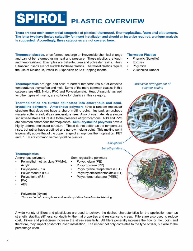
Molecular arrangement ofpolymer chains
Amorphous
Semi-Crystalline
A wide variety of fillers and plasticizers are used to achieve the desired characteristics for the application such as strength, stability, stiffness, conductivity, thermal properties and resistance to creep. Fillers are also used to reduce cost. Fillers and plasticizers increase the stress sensitivity. All fillers generally increase the flow or melt point and therefore, they impact post-mold Insert installation. The impact not only correlates to the type of filler, but also to the percentage used.
Thermoplastics are rigid and solid at normal temperatures but at elevated temperatures they soften and melt. Some of the more common plastics in this category are ABS, Nylon, PVC and Polycarbonate. Heat/Ultrasonic, as well as other types of Inserts, are suitable for plastics in this category.
Thermoplastics are further delineated into amorphous and semi-crystalline polymers. Amorphous polymers have a random molecular structure that does not have a sharp melting point. Instead, amorphous material softens gradually as temperature rises. Amorphous materials are more sensitive to stress failure due to the presence of hydrocarbons. ABS and PVC are common amorphous thermoplastics. Semi-crystalline polymers have a highly ordered molecular structure. These do not soften as the temperature rises, but rather have a defined and narrow melting point. This melting point is generally above that of the upper range of amorphous thermoplastics. PET and PEEK are common semi-crystalline plastics.
Thermoset plastics, once formed, undergo an irreversible chemical change and cannot be reformed using heat and pressure. These plastics are tough and heat-resistant. Examples are Bakelite, urea and polyester resins. Heat/Ultrasonic Inserts are not suitable for these plastics. Thermoset plastics require the use of Molded-In, Press-In, Expansion or Self-Tapping Inserts.
Thermoset Plastics• Phenolic (Bakelite)• Epoxies• Polyimide• Vulcanized Rubber
ThermoplasticsAmorphous polymers• Polymethyl methacrylate (PMMA),
Acrylic• Polystyrene (PS)• Polycarbonate (PC)• Polysulfone (PS)• PVC• ABS
Semi-crystalline polymers• Polyethelyne (PE)• Polypropylene (PP)• Polybutylene terephtalate (PBT)• Polyethylene terephthalate (PET)• Polyetheretherketone (PEEK)
• Polyamide (Nylon) This can be both amorphous and semi-crystalline based on the blending.
5
≥1.2L
D
L
≥A A
L
ØE
8°
Minimum Boss Dia.2-3 Times Insert Dia.
Minimum Hole Depth / Boss HeightInsert Length + 2 Thread Pitches
ØDTaper 1° Max
Minimum Boss Dia.2-3 Times Insert Dia.
Minimum Hole Depth / Boss HeightInsert Length + 2 Thread Pitches
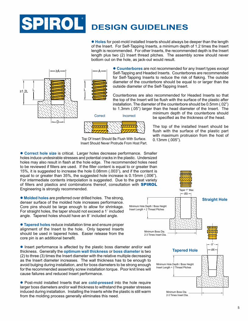
l Holes for post-mold installed Inserts should always be deeper than the length of the Insert. For Self-Tapping Inserts, a minimum depth of 1.2 times the Insert length is recommended. For other Inserts, the recommended depth is the Insert length plus two (2) Insert thread pitches. The assembly screw should never bottom out on the hole, as jack-out would result.
l Counterbores are not recommended for any Insert types except Self-Tapping and Headed Inserts. Counterbores are recommended for Self-Tapping Inserts to reduce the risk of flaking. The outside diameter of the counterbore should be equal to or larger than the outside diameter of the Self-Tapping Insert.
Counterbores are also recommended for Headed Inserts so that the top of the Insert will be flush with the surface of the plastic after installation. The diameter of the counterbore should be 0.5mm (.02”) to 1.3mm (.05”) larger than the head diameter of the Insert. The
minimum depth of the counterbore should be specified as the thickness of the head.
The top of the installed Insert should be flush with the surface of the plastic part with maximum protrusion from the host of 0.13mm (.005”).
DESIGN GUIDELINES
Straight Hole
Tapered Hole
Correct Incorrect
Top Of Insert Should Be Flush With Surface.Insert Should Never Protrude From Host Part.
l Correct hole size is critical. Larger holes decrease performance. Smaller holes induce undesirable stresses and potential cracks in the plastic. Undersized holes may also result in flash at the hole edge. The recommended holes need to be reviewed if fillers are used. If the filler content is equal to or greater than 15%, it is suggested to increase the hole 0.08mm (.003”), and if the content is equal to or greater than 35%, the suggested hole increase is 0.15mm (.006”). For intermediate contents interpolation is suggested. Due to the great variety of fillers and plastics and combinations thereof, consultation with SPIROL Engineering is strongly recommended.
l Molded holes are preferred over drilled holes. The strong, denser surface of the molded hole increases performance. Core pins should be large enough to allow for shrinkage. For straight holes, the taper should not exceed a 1˚ included angle. Tapered holes should have an 8˚ included angle.
l Tapered holes reduce installation time and ensure proper alignment of the Insert to the hole. Only tapered Inserts should be used in tapered holes. Easier release from the core pin is an additional benefit.
l Insert performance is affected by the plastic boss diameter and/or wall thickness. Generally the optimum wall thickness or boss diameter is two (2) to three (3) times the Insert diameter with the relative multiple decreasing as the Insert diameter increases. The wall thickness has to be enough to avoid bulging during installation, and for boss diameters to be strong enough for the recommended assembly screw installation torque. Poor knit lines will cause failures and reduced Insert performance.
l Post-mold installed Inserts that are cold-pressed into the hole require larger boss diameters and/or wall thickness to withstand the greater stresses induced during installation. Installing the Inserts while the plastic is still warm from the molding process generally eliminates this need.
6
Host
Mating Part
Headed Insert
Pull-Through Configuration
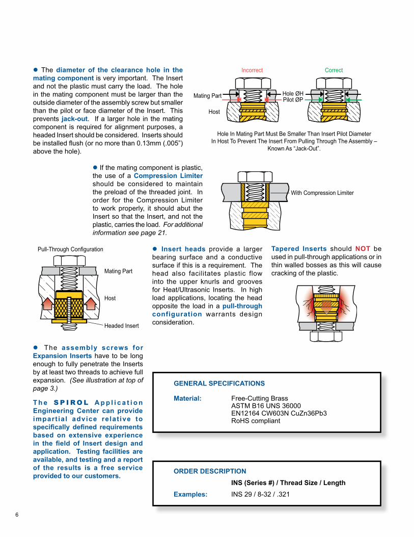
l The diameter of the clearance hole in the mating component is very important. The Insert and not the plastic must carry the load. The hole in the mating component must be larger than the outside diameter of the assembly screw but smaller than the pilot or face diameter of the Insert. This prevents jack-out. If a larger hole in the mating component is required for alignment purposes, a headed Insert should be considered. Inserts should be installed flush (or no more than 0.13mm (.005”)above the hole).
T h e S P I R O L A p p l i c a t i o n Engineering Center can provide impart ia l advice relat ive to specifically defined requirements based on extensive experience in the field of Insert design and application. Testing facilities are available, and testing and a report of the results is a free service provided to our customers. ORDER DESCRIPTION
INS (Series #) / Thread Size / LengthExamples: INS 29 / 8-32 / .321
GENERAL SPECIFICATIONS
Material: Free-Cutting Brass ASTM B16 UNS 36000 EN12164 CW603N CuZn36Pb3 RoHS compliant
l If the mating component is plastic, the use of a Compression Limiter should be considered to maintain the preload of the threaded joint. In order for the Compression Limiter to work properly, it should abut the Insert so that the Insert, and not the plastic, carries the load. For additional information see page 21.
l Insert heads provide a larger bearing surface and a conductive surface if this is a requirement. The head also facilitates plastic flow into the upper knurls and grooves for Heat/Ultrasonic Inserts. In high load applications, locating the head opposite the load in a pull-through configuration warrants design consideration.
Tapered Inserts should NOT be used in pull-through applications or in thin walled bosses as this will cause cracking of the plastic.
Host
Mating Part
Incorrect Correct
Hole In Mating Part Must Be Smaller Than Insert Pilot DiameterIn Host To Prevent The Insert From Pulling Through The Assembly –
Known As “Jack-Out”.
Hole ØHPilot ØP
With Compression Limiter
l The assembly screws for Expansion Inserts have to be long enough to fully penetrate the Inserts by at least two threads to achieve full expansion. (See illustration at top of page 3.)
7
SPIROL INSERTS
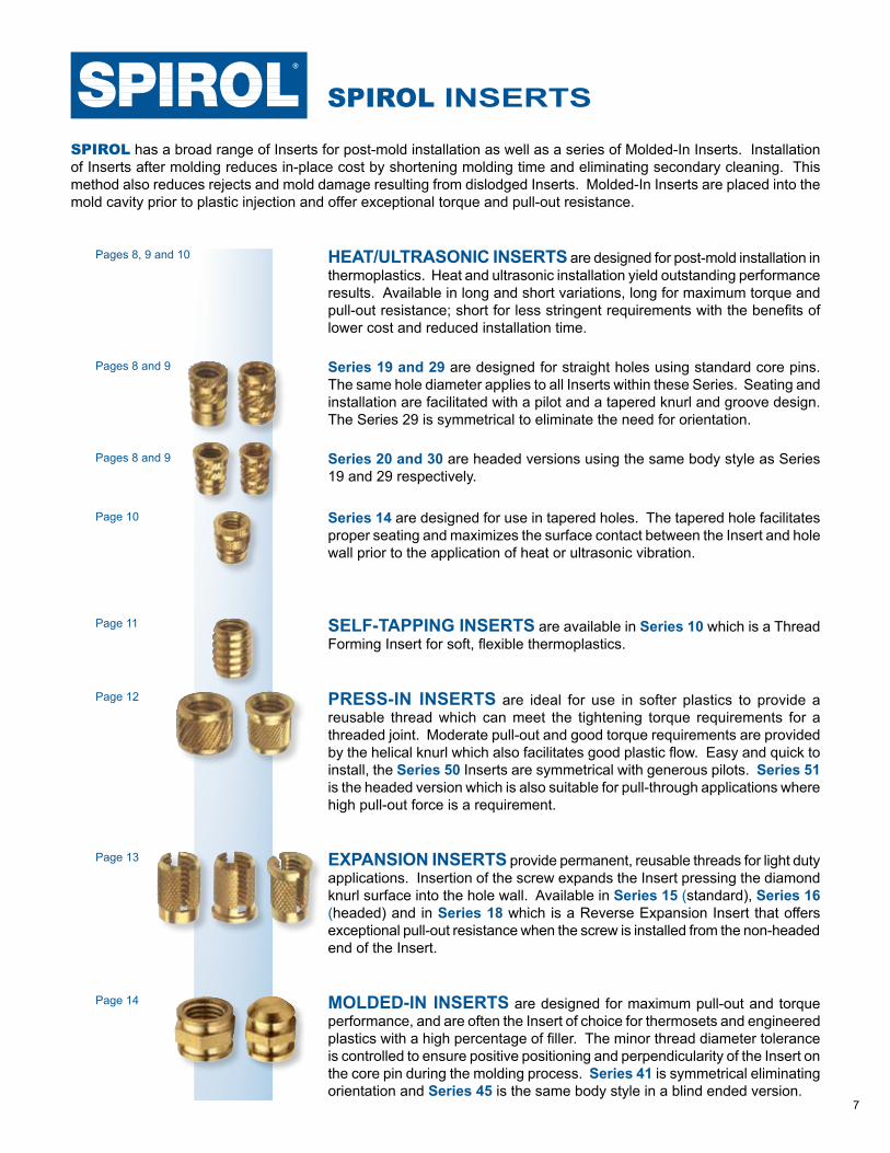
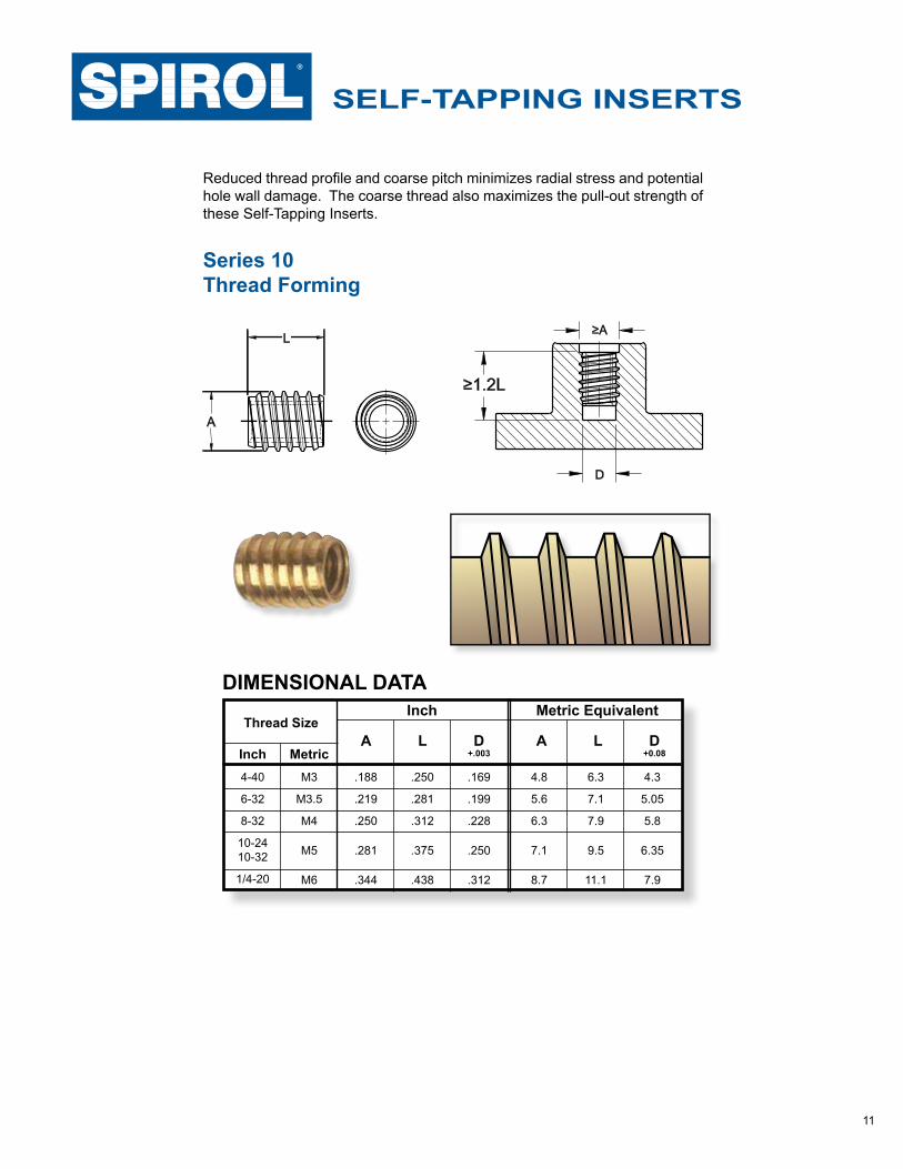
SELF-TAPPING INSERTS are available in Series 10 which is a Thread Forming Insert for soft, flexible thermoplastics.
SPIROL has a broad range of Inserts for post-mold installation as well as a series of Molded-In Inserts. Installation of Inserts after molding reduces in-place cost by shortening molding time and eliminating secondary cleaning. This method also reduces rejects and mold damage resulting from dislodged Inserts. Molded-In Inserts are placed into the mold cavity prior to plastic injection and offer exceptional torque and pull-out resistance.
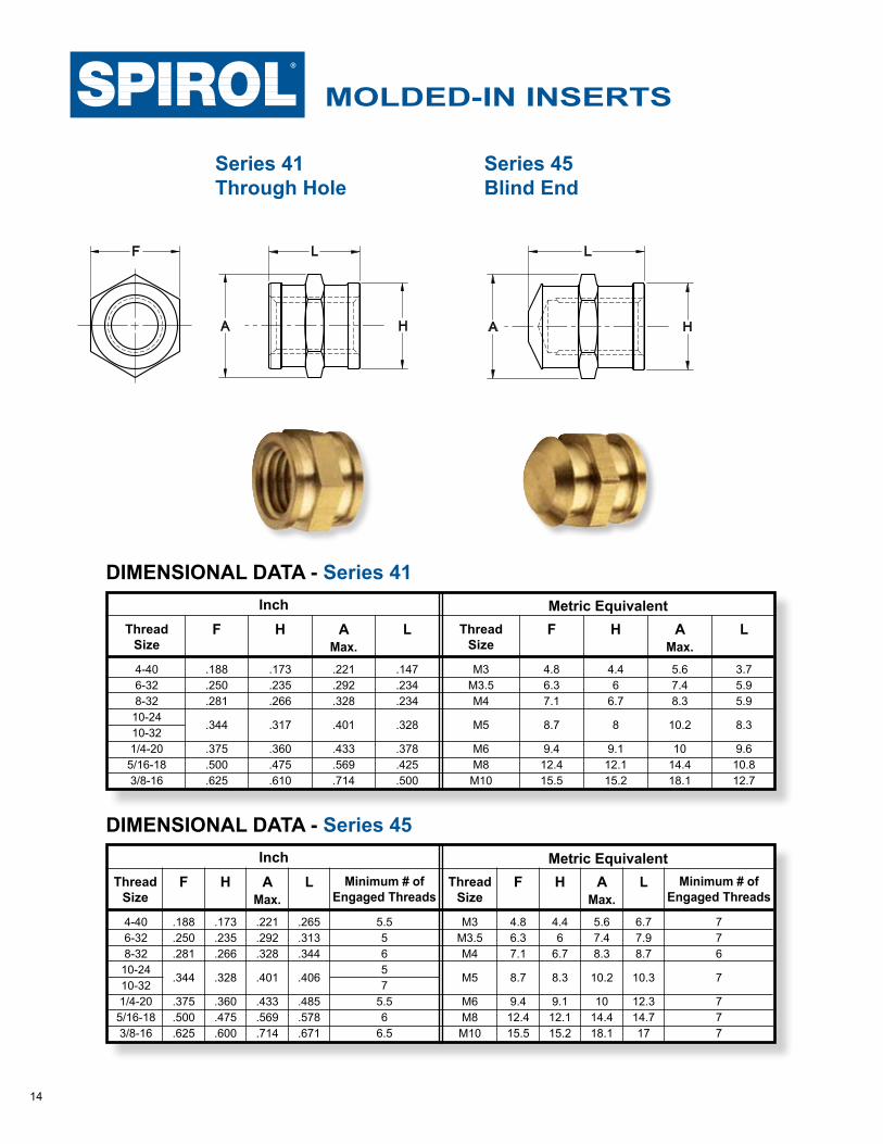
MOLDED-IN INSERTS are designed for maximum pull-out and torque performance, and are often the Insert of choice for thermosets and engineered plastics with a high percentage of filler. The minor thread diameter tolerance is controlled to ensure positive positioning and perpendicularity of the Insert on the core pin during the molding process. Series 41 is symmetrical eliminating orientation and Series 45 is the same body style in a blind ended version.
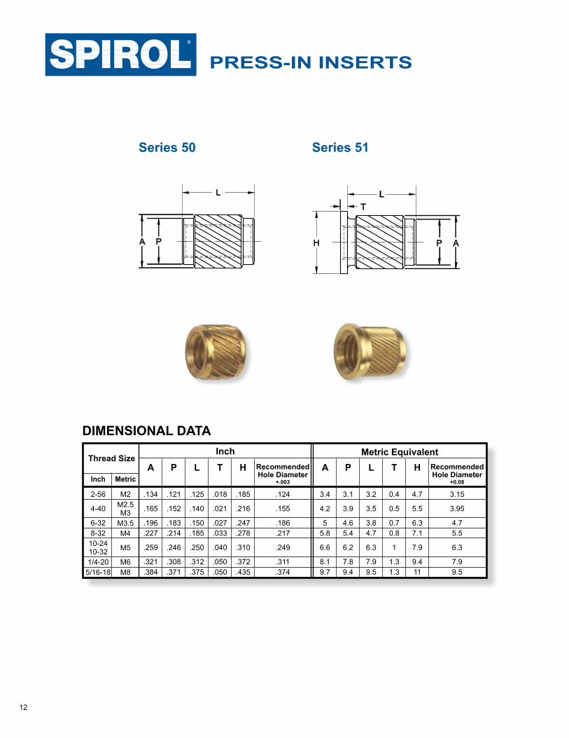
PRESS-IN INSERTS are ideal for use in softer plastics to provide a reusable thread which can meet the tightening torque requirements for a threaded joint. Moderate pull-out and good torque requirements are provided by the helical knurl which also facilitates good plastic flow. Easy and quick to install, the Series 50 Inserts are symmetrical with generous pilots. Series 51 is the headed version which is also suitable for pull-through applications where high pull-out force is a requirement.
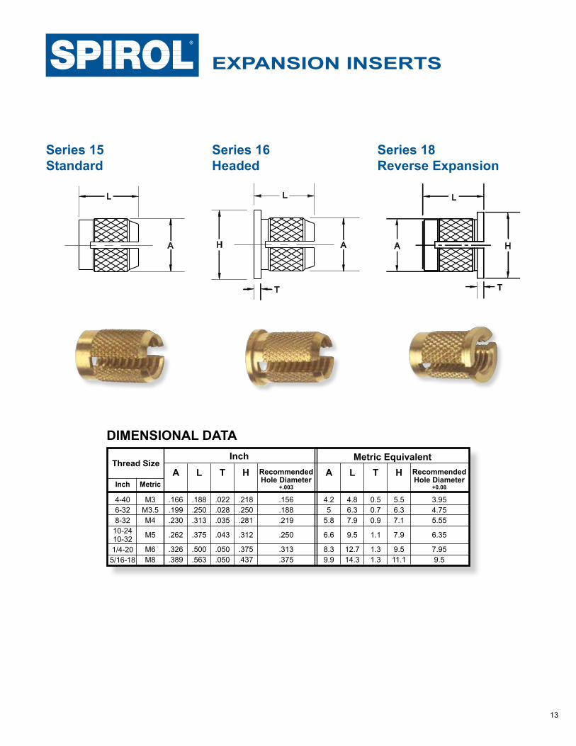
EXPANSION INSERTS provide permanent, reusable threads for light duty applications. Insertion of the screw expands the Insert pressing the diamond knurl surface into the hole wall. Available in Series 15 (standard), Series 16 (headed) and in Series 18 which is a Reverse Expansion Insert that offers exceptional pull-out resistance when the screw is installed from the non-headed end of the Insert.
HEAT/ULTRASONIC INSERTS are designed for post-mold installation in thermoplastics. Heat and ultrasonic installation yield outstanding performance results. Available in long and short variations, long for maximum torque and pull-out resistance; short for less stringent requirements with the benefits of lower cost and reduced installation time.
Series 19 and 29 are designed for straight holes using standard core pins. The same hole diameter applies to all Inserts within these Series. Seating and installation are facilitated with a pilot and a tapered knurl and groove design. The Series 29 is symmetrical to eliminate the need for orientation.
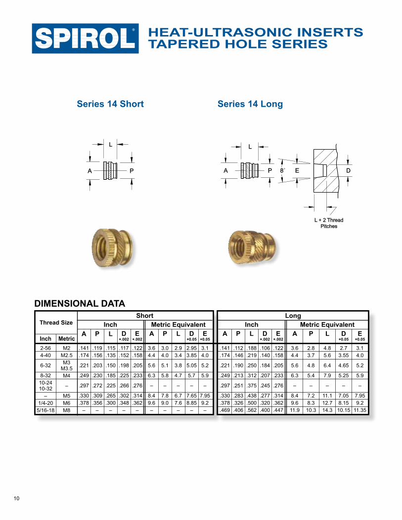
Series 14 are designed for use in tapered holes. The tapered hole facilitates proper seating and maximizes the surface contact between the Insert and hole wall prior to the application of heat or ultrasonic vibration.
Series 20 and 30 are headed versions using the same body style as Series 19 and 29 respectively.
Pages 8 and 9
Pages 8 and 9
Page 10
Page 11
Page 12
Page 13
Page 14
Pages 8, 9 and 10
8
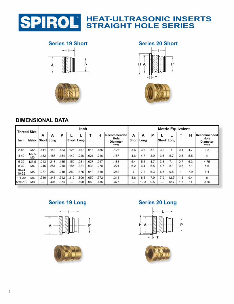
STRAIGHT HOLE SERIESHEAT-ULTRASONIC INSERTS
Series 19 Short Series 20 Short
Series 20 LongSeries 19 Long
DIMENSIONAL DATA
Thread Size
Inch MetricHT Recommended
HoleDiameter
+.003
P
2-56
4-40
6-328-3210-2410-321/4-205/16-18
M2M2.5M3
M3.5M4
M5
M6M8
.143
.187
.218
.251
.282
.345
.407
.157
.226
.281
.321
.375
.500
.500
.125
.140
.150
.185
.250
.312—
.185
.216
.247
.278
.310
.372
.435
.018
.021
.027
.033
.040
.050
.050
.126
.157
.188
.221
.252
.315
.377
.141
.182
.213
.246
.277
.340—
.123
.154
.185
.218
.249
.312
.374
LShort
LLong
AShort
ALong
3.6
4.7
5.56.4
7.2
8.810.3
4
5.7
7.18.1
9.5
12.712.7
3.2
3.5
3.84.7
6.3
7.9—
4.7
5.5
6.37.1
7.9
9.411
H
0.4
0.5
0.70.8
1
1.31.3
T Recommended Hole
Diameter+0.08
3.2
4
4.755.6
6.4
89.55
3.6
4.6
5.46.2
7
8.6—
P
3.1
3.9
4.75.5
6.3
7.99.5
LShort
LLong
AShort
ALong
Metric EquivalentInch
A
L
P
A P
L
H A
L
P
T
H A
L
P
T
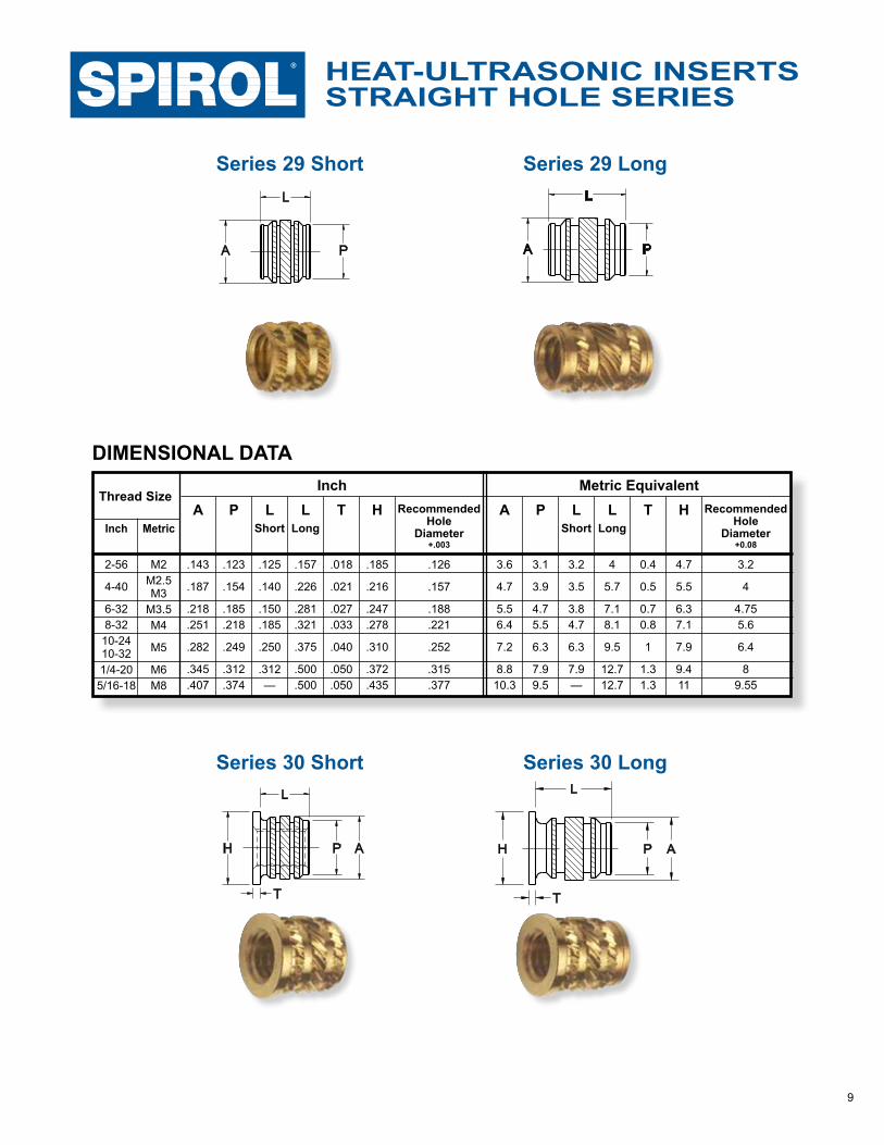
9
STRAIGHT HOLE SERIESHEAT-ULTRASONIC INSERTS
DIMENSIONAL DATA
2-56
4-40
6-328-3210-2410-321/4-205/16-18
M2M2.5M3
M3.5M4
M5
M6M8
Thread Size
.123
.154
.185
.218
.249
.312
.374
.125
.140
.150
.185
.250
.312—
.157
.226
.281
.321
.375
.500
.500
.185
.216
.247
.278
.310
.372
.435
.018
.021
.027
.033
.040
.050
.050
.126
.157
.188
.221
.252
.315
.377
Inch MetricP L
ShortL
LongHT Recommended
HoleDiameter
+.003
A
.143
.187
.218
.251
.282
.345
.407
Metric EquivalentInchP
3.1
3.9
4.75.5
6.3
7.99.5
LShort
3.2
3.5
3.84.7
6.3
7.9—
LLong
4
5.7
7.18.1
9.5
12.712.7
4.7
5.5
6.37.1
7.9
9.411
H
0.4
0.5
0.70.8
1
1.31.3
T RecommendedHole
Diameter+0.08
3.2
4
4.755.6
6.4
89.55
A
3.6
4.7
5.56.4
7.2
8.810.3
Series 29 LongSeries 29 Short
A P
L L
A P
Series 30 LongSeries 30 Short
H P A
T
L
H P A
T
L
10
TAPERED HOLE SERIESHEAT-ULTRASONIC INSERTS
Series 14 Short Series 14 Long
DIMENSIONAL DATAShort Long
2-564-40
6-32
8-3210-2410-32
–1/4-205/16-18
M2M2.5M3
M3.5M4
–
M5M6M8
Thread Size
Inch MetricL E
+.002D
+.002A P
.117
.152
.198
.225
.266
.302
.348–
.115
.135
.150
.185
.225
.265
.300–
.141
.174
.221
.249
.297
.330
.378–
.122
.158
.205
.233
.276
.314
.362–
.119
.156
.203
.230
.272
.309
.356–
.106
.140
.184
.207
.245
.277
.320
.400
.188
.219
.250
.312
.375
.438
.500
.562
.141
.174
.221
.249
.297
.330
.378
.469
.122
.158
.205
.233
.276
.314
.362
.447
.112
.146
.190
.213
.251
.283
.326
.406
L E +.002
D +.002
A PL E +0.05
D +0.05
A P
2.953.85
5.05
5.7
–
7.658.85
–
2.93.4
3.8
4.7
–
6.77.6–
3.64.4
5.6
6.3
–
8.49.6–
3.14.0
5.2
5.9
–
7.959.2–
3.04.0
5.1
5.8
–
7.89.0–
2.73.55
4.65
5.25
–
7.058.1510.15
4.85.6
6.4
7.9
–
11.112.714.3
3.64.4
5.6
6.3
–
8.49.611.9
3.14.0
5.2
5.9
–
7.959.2
11.35
2.83.7
4.8
5.4
–
7.28.310.3
L E +0.05
D +0.05
A PMetric EquivalentInch Metric EquivalentInch
A
L
8˚P E D
L + 2 ThreadPitches
P 8˚ E D
L
A
11
SELF-TAPPING INSERTS
Reduced thread profile and coarse pitch minimizes radial stress and potential hole wall damage. The coarse thread also maximizes the pull-out strength of these Self-Tapping Inserts.
DIMENSIONAL DATA
.250
.281
.312
.375
.438
.188
.219
.250
.281
.344
D+.003
.169
.199
.228
.250
.312
LAThread Size
4-40
6-32
8-32
10-2410-32
1/4-20
M3
M3.5
M4
M5
M6
Inch Metric6.3
7.1
7.9
9.5
11.1
4.8
5.6
6.3
7.1
8.7
D+0.08
4.3
5.05
5.8
6.35
7.9
LA
Inch Metric Equivalent
Series 10Thread Forming
A
L ≥A
D
≥1.2L
12
PRESS-IN INSERTS
Series 51Series 50
DIMENSIONAL DATA
2-56
4-40
6-328-3210-2410-321/4-205/16-18
M2M2.5M3
M3.5M4
M5
M6M8
L
.125
.140
.150
.185
.250
.312
.375
A
.134
.165
.196
.227
.259
.321
.384
P
.121
.152
.183
.214
.246
.308
.371
.185
.216
.247
.278
.310
.372
.435
H
.018
.021
.027
.033
.040
.050
.050
T Recommended Hole Diameter
+.003
.124
.155
.186
.217
.249
.311
.374
L
3.2
3.5
3.84.7
6.3
7.99.5
A
3.4
4.2
55.8
6.6
8.19.7
P
3.1
3.9
4.65.4
6.2
7.89.4
4.7
5.5
6.37.1
7.9
9.411
H
0.4
0.5
0.70.8
1
1.31.3
T Recommended Hole Diameter
+0.08
3.15
3.95
4.75.5
6.3
7.99.5
Thread Size
Inch Metric
Metric EquivalentInch
PA
L
P A
L
H
T
13
EXPANSION INSERTS
Series 16Headed
Series 15Standard
Series 18Reverse Expansion
DIMENSIONAL DATA
4-406-328-3210-2410-321/4-205/16-18
M3M3.5M4
M5
M6M8
A
.166
.199
.230
.262
.326
.389
L
.188
.250
.313
.375
.500
.563
.218
.250
.281
.312
.375
.437
H
.022
.028
.035
.043
.050
.050
T Recommended Hole Diameter
+.003
.156
.188
.219
.250
.313
.375
A
4.25
5.8
6.6
8.39.9
L
4.86.37.9
9.5
12.714.3
5.56.37.1
7.9
9.511.1
H
0.50.70.9
1.1
1.31.3
T Recommended Hole Diameter
+0.08
3.954.755.55
6.35
7.959.5
Thread Size
Inch Metric
Metric EquivalentInch
L
A H
T
H
L
A
T
A
L
14
MOLDED-IN INSERTS
Series 45Blind End
Series 41Through Hole
DIMENSIONAL DATA - Series 45Metric Equivalent
4-406-328-3210-2410-321/4-205/16-183/8-16
Thread Size
A
.221
.292
.328
.401
.433
.569
.714
F
.188
.250
.281
.344
.375
.500
.625
H
.173
.235
.266
.328
.360
.475
.600
.265
.313
.344
.406
.485
.578
.671
LMax.
A
5.67.48.3
10.2
1014.418.1
F
4.86.3 7.1
8.7
9.4 12.415.5
H
4.46
6.7
8.3
9.112.115.2
6.77.98.7
10.3
12.314.717
LMax.
InchMinimum # of
Engaged Threads
5.55657
5.56
6.5
Minimum # ofEngaged Threads
776
7
777
M3M3.5M4
M5
M6M8 M10
Thread Size
DIMENSIONAL DATA - Series 41Metric Equivalent
4-406-328-3210-2410-321/4-205/16-183/8-16
Thread Size
A
.221
.292
.328
.401
.433
.569
.714
F
.188
.250
.281
.344
.375
.500
.625
H
.173
.235
.266
.317
.360
.475
.610
.147
.234
.234
.328
.378
.425
.500
LMax.
A
5.67.48.3
10.2
1014.418.1
F
4.86.3 7.1
8.7
9.4 12.415.5
H
4.46
6.7
8
9.112.115.2
3.75.95.9
8.3
9.610.812.7
LMax.
Inch
M3M3.5M4
M5
M6M8 M10
Thread Size
L
H
L
A H
F
A
L
H
L
A H
F
A
15
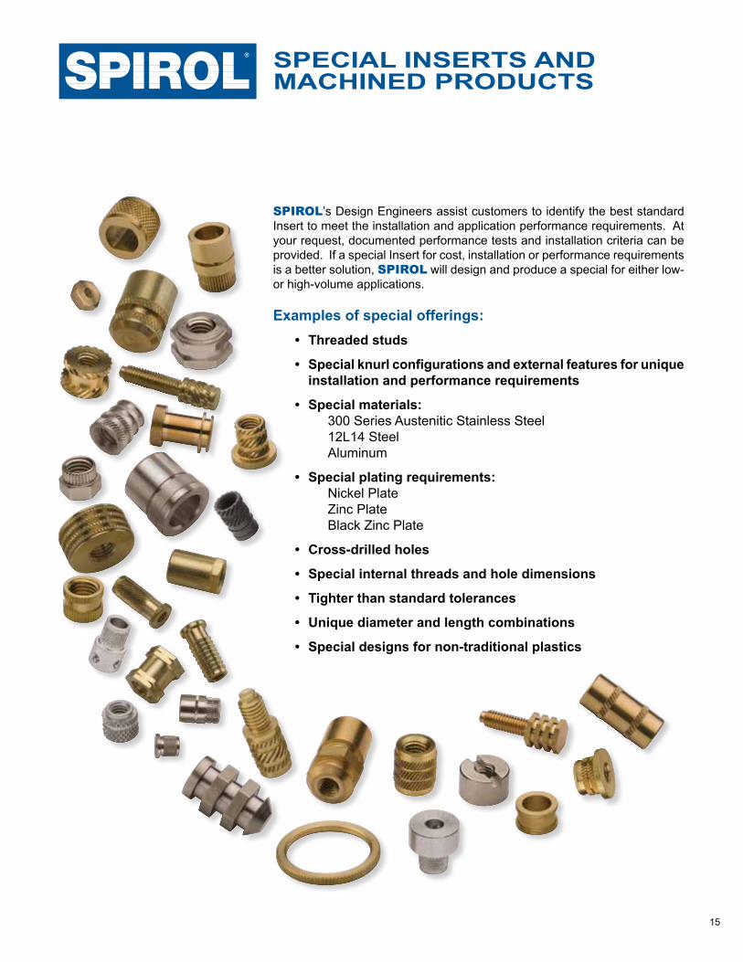
SPIROL’s Design Engineers assist customers to identify the best standard Insert to meet the installation and application performance requirements. At your request, documented performance tests and installation criteria can be provided. If a special Insert for cost, installation or performance requirements is a better solution, SPIROL will design and produce a special for either low- or high-volume applications.
Examples of special offerings:• Threaded studs
• Special knurl configurations and external features for unique installation and performance requirements
• Special materials: 300 Series Austenitic Stainless Steel 12L14 Steel Aluminum
• Special plating requirements: Nickel Plate Zinc Plate Black Zinc Plate
• Cross-drilled holes
• Special internal threads and hole dimensions
• Tighter than standard tolerances
• Unique diameter and length combinations
• Special designs for non-traditional plastics
MACHINED PRODUCTSSPECIAL INSERTS AND
16
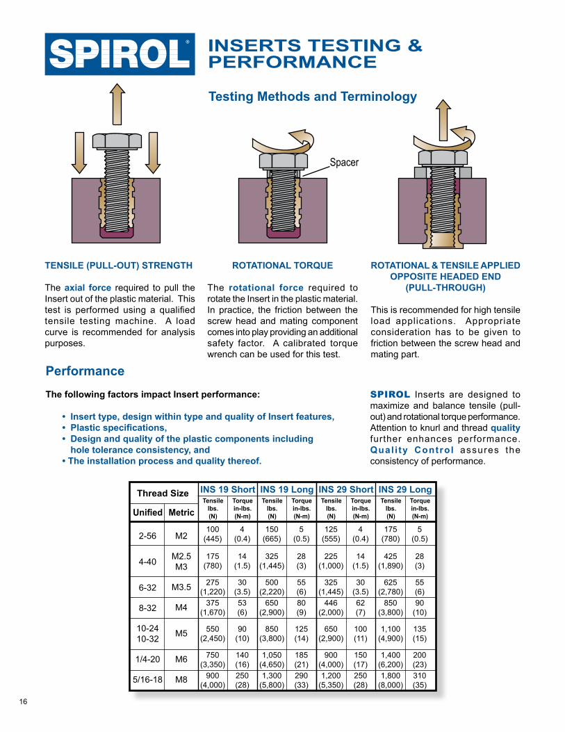
PERFORMANCEINSERTS TESTING &
Performance The following factors impact Insert performance:
• Insert type, design within type and quality of Insert features,• Plastic specifications,• Design and quality of the plastic components including hole tolerance consistency, and• The installation process and quality thereof.
SPIROL Inserts are designed to maximize and balance tensile (pull-out) and rotational torque performance. Attention to knurl and thread quality further enhances performance. Qual i ty Control assures the consistency of performance.
2-56
4-40
6-32
8-32
10-2410-32
1/4-20
5/16-18
M2
M2.5M3
M3.5
M4
M5
M6
M8
Thread Size
Unified Metric
100(445)
175(780)
275(1,220)
375(1,670)
550(2,450)
750(3,350)
900(4,000)
5(0.5)
28(3)
55(6)80(9)
125(14)
185(21)290(33)
150(665)
325(1,445)
500(2,220)
650(2,900)
850(3,800)
1,050(4,650)1,300
(5,800)
4(0.4)
14(1.5)
30(3.5)53(6)
90(10)
140(16)250(28)
Torquein-lbs. (N-m)
Tensilelbs.(N)
Torquein-lbs. (N-m)
Tensilelbs.(N)
INS 19 Short INS 19 Long
4(0.4)
14(1.5)
30(3.5)62(7)
100(11)
150(17)250(28)
125(555)
225(1,000)
325(1,445)
446(2,000)
650(2,900)
900(4,000)1,200
(5,350)
5(0.5)
28(3)
55(6)90
(10)
135(15)
200(23)310(35)
175(780)
425(1,890)
625(2,780)
850(3,800)
1,100(4,900)
1,400(6,200)1,800
(8,000)
Torquein-lbs. (N-m)
Tensilelbs.(N)
Tensilelbs.(N)
Torquein-lbs. (N-m)
INS 29 Short INS 29 Long
ROTATIONAL & TENSILE APPLIED OPPOSITE HEADED END
(PULL-THROUGH)
This is recommended for high tensile load applications. Appropriate consideration has to be given to friction between the screw head and mating part.
ROTATIONAL TORQUE
The rotational force required to rotate the Insert in the plastic material. In practice, the friction between the screw head and mating component comes into play providing an additional safety factor. A calibrated torque wrench can be used for this test.
TENSILE (PULL-OUT) STRENGTH
The axial force required to pull the Insert out of the plastic material. This test is performed using a qualified tensile testing machine. A load curve is recommended for analysis purposes.
Spacer
Testing Methods and Terminology
17
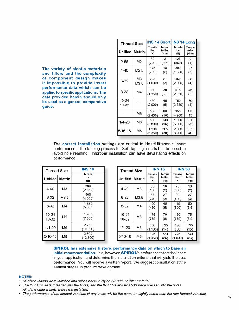
2-56
4-40
6-32
8-32
10-2410-32
—
1/4-20
5/16-18
M2
M2.5
M3M3.5
M4
—
M5
M6
M8
Thread Size
Unified Metric
50(220)175
(780)
225(1,000)
300(1,350)
450(2,000)
550(2,450)
850(3,800)1,200
(5,350)
9(1)27(3)
35(4)
45(5)
70(8)
135(15)220(25)355(40)
125(560)300
(1,330)
450(2,000)
575(2,550)
750(3,330)
950(4,200)1,300
(5,800)2,000
(8,900)
3(0.3)18(2)
27(3)
30(3.5)
45(5)
88(10)140(16)265(30)
Torquein-lbs. (N-m)
Tensilelbs.(N)
Torquein-lbs. (N-m)
Tensilelbs.(N)
INS 14 Short INS 14 Long
The variety of plastic materials and fillers and the complexity of component design makes it impossible to provide Insert performance data which can be applied to specific applications. The data provided herein should only be used as a general comparative guide.
4-40
6-32
8-32
10-2410-32
1/4-20
5/16-18
M3
M3.5
M4
M5
M6
M8
Thread Size
Unified Metric600
(2,650)900
(4,000)1,225
(5,500)
1,700(7,500)
2,250(10,000)
2,800(12,500)
Tensilelbs.(N)
INS 10
The correct installation settings are critical to Heat/Ultrasonic Insert performance. The tapping process for Self-Tapping Inserts has to be set to avoid hole reaming. Improper installation can have devastating effects on performance.
SPIROL has extensive historic performance data on which to base an initial recommendation. It is, however, SPIROL's preference to test the Insert in your application and determine the installation criteria that will yield the best performance. You will receive a written report. We suggest consultation at the earliest stages in product development.
4-40
6-32
8-32
10-2410-32
1/4-20
5/16-18
M3
M3.5
M4
M5
M6
M8
Thread Size
Unified Metric
30(130)
55(240)100
(450)
175(775)
250(1,100)
325(1,450)
18(2)27(3)50
(5.5)
75(8.5)
135(15)230(26)
75(330)
90(400)115
(500)
150(675)
180(800)225
(1,000)
18(2)27(3)45(5)
70(8)
125(14)220(25)
Torquein-lbs. (N-m)
Tensilelbs.(N)
Torquein-lbs. (N-m)
Tensilelbs.(N)
INS 15 INS 50
NOTES:• All of the Inserts were installed into drilled holes in Nylon 6/6 with no filler material.• The INS 10’s were threaded into the holes, and the INS 15’s and INS 50’s were pressed into the holes. All of the other Inserts were heat installed.• The performance of the headed versions of any Insert will be the same or slightly better than the non-headed versions.
18
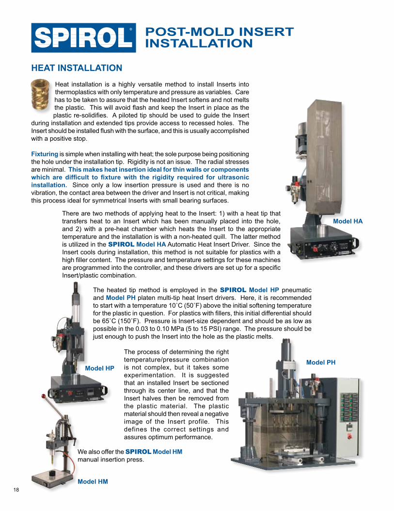
HEAT INSTALLATIONHeat installation is a highly versatile method to install Inserts into thermoplastics with only temperature and pressure as variables. Care has to be taken to assure that the heated Insert softens and not melts the plastic. This will avoid flash and keep the Insert in place as the plastic re-solidifies. A piloted tip should be used to guide the Insert
during installation and extended tips provide access to recessed holes. The Insert should be installed flush with the surface, and this is usually accomplished with a positive stop.
Fixturing is simple when installing with heat; the sole purpose being positioning the hole under the installation tip. Rigidity is not an issue. The radial stresses are minimal. This makes heat insertion ideal for thin walls or components which are difficult to fixture with the rigidity required for ultrasonic installation. Since only a low insertion pressure is used and there is no vibration, the contact area between the driver and Insert is not critical, making this process ideal for symmetrical Inserts with small bearing surfaces.
INSTALLATIONPOST-MOLD INSERT
Model HA
Model PHModel HP
There are two methods of applying heat to the Insert: 1) with a heat tip that transfers heat to an Insert which has been manually placed into the hole, and 2) with a pre-heat chamber which heats the Insert to the appropriate temperature and the installation is with a non-heated quill. The latter method is utilized in the SPIROL Model HA Automatic Heat Insert Driver. Since the Insert cools during installation, this method is not suitable for plastics with a high filler content. The pressure and temperature settings for these machines are programmed into the controller, and these drivers are set up for a specific Insert/plastic combination.
The heated tip method is employed in the SPIROL Model HP pneumatic and Model PH platen multi-tip heat Insert drivers. Here, it is recommended to start with a temperature 10˚C (50˚F) above the initial softening temperature for the plastic in question. For plastics with fillers, this initial differential should be 65˚C (150˚F). Pressure is Insert-size dependent and should be as low as possible in the 0.03 to 0.10 MPa (5 to 15 PSI) range. The pressure should be just enough to push the Insert into the hole as the plastic melts.
The process of determining the right temperature/pressure combination is not complex, but it takes some experimentation. It is suggested that an installed Insert be sectioned through its center line, and that the Insert halves then be removed from the plastic material. The plastic material should then reveal a negative image of the Insert profile. This defines the correct settings and assures optimum performance.
Model HM
We also offer the SPIROL Model HM manual insertion press.
19
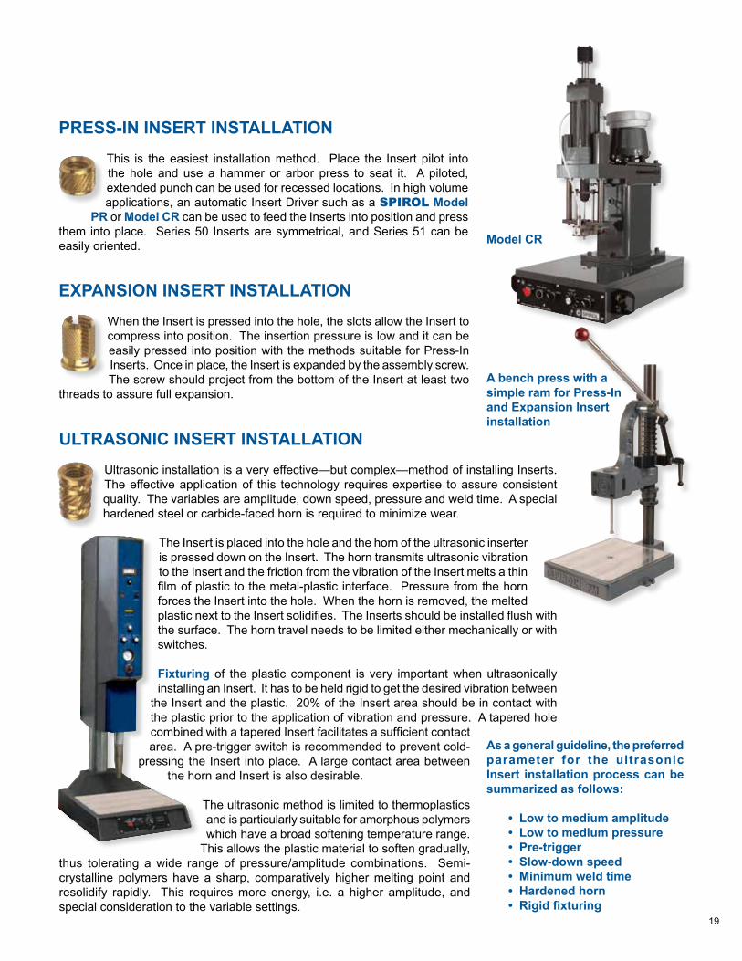
PRESS-IN INSERT INSTALLATIONThis is the easiest installation method. Place the Insert pilot into the hole and use a hammer or arbor press to seat it. A piloted, extended punch can be used for recessed locations. In high volume applications, an automatic Insert Driver such as a SPIROL Model
PR or Model CR can be used to feed the Inserts into position and press them into place. Series 50 Inserts are symmetrical, and Series 51 can be easily oriented.
ULTRASONIC INSERT INSTALLATIONUltrasonic installation is a very effective—but complex—method of installing Inserts. The effective application of this technology requires expertise to assure consistent quality. The variables are amplitude, down speed, pressure and weld time. A special hardened steel or carbide-faced horn is required to minimize wear.
The Insert is placed into the hole and the horn of the ultrasonic inserter is pressed down on the Insert. The horn transmits ultrasonic vibration to the Insert and the friction from the vibration of the Insert melts a thin film of plastic to the metal-plastic interface. Pressure from the horn forces the Insert into the hole. When the horn is removed, the melted plastic next to the Insert solidifies. The Inserts should be installed flush with the surface. The horn travel needs to be limited either mechanically or with switches.
Fixturing of the plastic component is very important when ultrasonically installing an Insert. It has to be held rigid to get the desired vibration between
the Insert and the plastic. 20% of the Insert area should be in contact with the plastic prior to the application of vibration and pressure. A tapered hole combined with a tapered Insert facilitates a sufficient contact area. A pre-trigger switch is recommended to prevent cold-
pressing the Insert into place. A large contact area between the horn and Insert is also desirable.
The ultrasonic method is limited to thermoplastics and is particularly suitable for amorphous polymers which have a broad softening temperature range.
This allows the plastic material to soften gradually, thus tolerating a wide range of pressure/amplitude combinations. Semi-crystalline polymers have a sharp, comparatively higher melting point and resolidify rapidly. This requires more energy, i.e. a higher amplitude, and special consideration to the variable settings.
As a general guideline, the preferred parameter for the ultrasonic Insert installation process can be summarized as follows:
• Low to medium amplitude• Low to medium pressure• Pre-trigger• Slow-down speed• Minimum weld time• Hardened horn• Rigid fixturing
EXPANSION INSERT INSTALLATIONWhen the Insert is pressed into the hole, the slots allow the Insert to compress into position. The insertion pressure is low and it can be easily pressed into position with the methods suitable for Press-In Inserts. Once in place, the Insert is expanded by the assembly screw. The screw should project from the bottom of the Insert at least two
threads to assure full expansion.A bench press with a simple ram for Press-In and Expansion Insertinstallation
Model CR
20
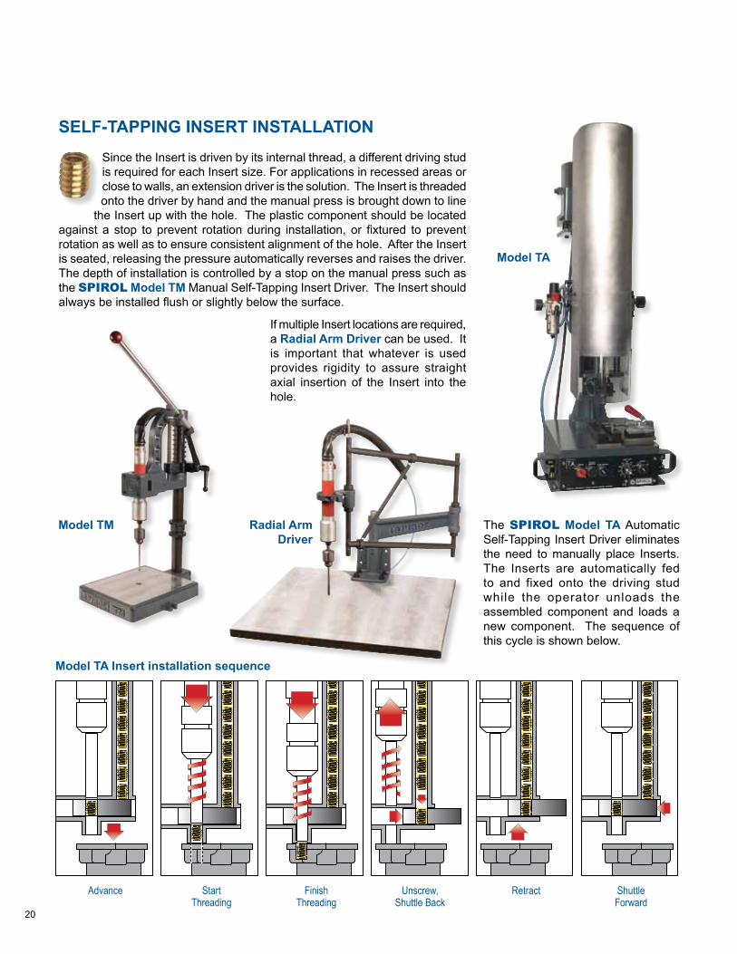
SELF-TAPPING INSERT INSTALLATIONSince the Insert is driven by its internal thread, a different driving stud is required for each Insert size. For applications in recessed areas or close to walls, an extension driver is the solution. The Insert is threaded onto the driver by hand and the manual press is brought down to line
the Insert up with the hole. The plastic component should be located against a stop to prevent rotation during installation, or fixtured to prevent rotation as well as to ensure consistent alignment of the hole. After the Insert is seated, releasing the pressure automatically reverses and raises the driver. The depth of installation is controlled by a stop on the manual press such as the SPIROL Model TM Manual Self-Tapping Insert Driver. The Insert should always be installed flush or slightly below the surface.
If multiple Insert locations are required, a Radial Arm Driver can be used. It is important that whatever is used provides rigidity to assure straight axial insertion of the Insert into the hole.
The SPIROL Model TA Automatic Self-Tapping Insert Driver eliminates the need to manually place Inserts. The Inserts are automatically fed to and fixed onto the driving stud while the operator unloads the assembled component and loads a new component. The sequence of this cycle is shown below.
Model TA
Model TM Radial Arm Driver
Advance Start Finish Unscrew, Retract Shuttle Threading Threading Shuttle Back Forward
Model TA Insert installation sequence
21
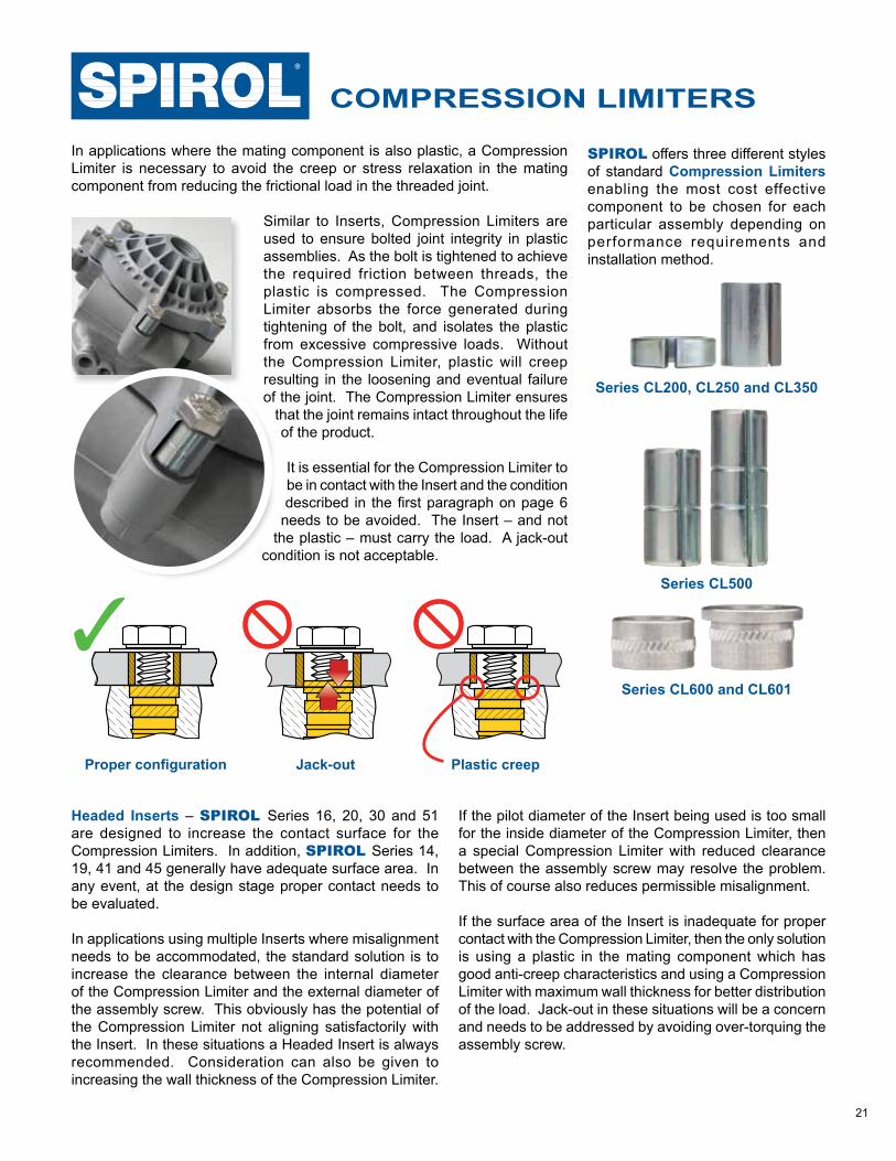
Proper configuration Plastic creepJack-out
COMPRESSION LIMITERS
In applications where the mating component is also plastic, a Compression Limiter is necessary to avoid the creep or stress relaxation in the mating component from reducing the frictional load in the threaded joint.
Similar to Inserts, Compression Limiters are used to ensure bolted joint integrity in plastic assemblies. As the bolt is tightened to achieve the required friction between threads, the plastic is compressed. The Compression Limiter absorbs the force generated during tightening of the bolt, and isolates the plastic from excessive compressive loads. Without the Compression Limiter, plastic will creep resulting in the loosening and eventual failure of the joint. The Compression Limiter ensures
that the joint remains intact throughout the life of the product.
It is essential for the Compression Limiter to be in contact with the Insert and the condition described in the first paragraph on page 6
needs to be avoided. The Insert – and not the plastic – must carry the load. A jack-out
condition is not acceptable.
SPIROL offers three different styles of standard Compression Limiters enabling the most cost effective component to be chosen for each particular assembly depending on performance requirements and installation method.
Headed Inserts – SPIROL Series 16, 20, 30 and 51 are designed to increase the contact surface for the Compression Limiters. In addition, SPIROL Series 14, 19, 41 and 45 generally have adequate surface area. In any event, at the design stage proper contact needs to be evaluated.
In applications using multiple Inserts where misalignment needs to be accommodated, the standard solution is to increase the clearance between the internal diameter of the Compression Limiter and the external diameter of the assembly screw. This obviously has the potential of the Compression Limiter not aligning satisfactorily with the Insert. In these situations a Headed Insert is always recommended. Consideration can also be given to increasing the wall thickness of the Compression Limiter.
If the pilot diameter of the Insert being used is too small for the inside diameter of the Compression Limiter, then a special Compression Limiter with reduced clearance between the assembly screw may resolve the problem. This of course also reduces permissible misalignment.
If the surface area of the Insert is inadequate for proper contact with the Compression Limiter, then the only solution is using a plastic in the mating component which has good anti-creep characteristics and using a Compression Limiter with maximum wall thickness for better distribution of the load. Jack-out in these situations will be a concern and needs to be addressed by avoiding over-torquing the assembly screw.
Series CL600 and CL601
Series CL200, CL250 and CL350
Series CL500
4
SPIROL Application Engineers will review your application needs and work with your design team to recommend the best solution. One way to start the process is to visit our Optimal Application Engineering portal at www.SPIROL.com.
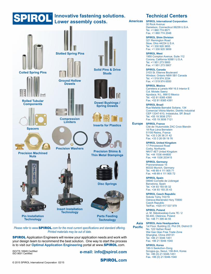
Innovative fastening solutions.Lower assembly costs.
Insert Installation Technology
Pin Installation Technology
Parts Feeding Technology
Ground Hollow Dowels
Coiled Spring Pins
Slotted Spring Pins
Solid Pins & Drive Studs
Rolled Tubular Components Dowel Bushings /
Spring Dowels
Inserts for PlasticsSpacers
Precision Shims &Thin Metal Stampings
Precision Washers
Disc Springs
Precision Machined Nuts
© 2015 SPIROL International Corporation 02/15
Compression Limiters
ISO/TS 16949 CertifiedISO 9001 Certified e-mail: [email protected]
SPIROL.com
Please refer to www.SPIROL.com for the most current specifications and standard offering. Printed materials may be out of date.
SPIROL International Corporation30 Rock AvenueDanielson, Connecticut 06239 U.S.A.Tel. +1 860 774 8571Fax. +1 860 774 2048
SPIROL Shim Division321 Remington RoadStow, Ohio 44224 U.S.A.Tel. +1 330 920 3655Fax. +1 330 920 3659
SPIROL West1950 Compton Avenue, Suite 112Corona, California 92881 U.S.A.Tel. +1 951 273 5900Fax. +1 951 273 5907
SPIROL Canada3103 St. Etienne BoulevardWindsor, Ontario N8W 5B1 CanadaTel. +1 519 974 3334Fax. +1 519 974 6550
SPIROL MexicoCarretera a Laredo KM 16.5 Interior ECol. Moisés SaenzApodaca, N.L. 66613 MexicoTel. +52 81 8385 4390Fax. +52 81 8385 4391
SPIROL BrazilRua Mafalda Barnabé Soliane, 134Comercial Vitória Martini, Distrito IndustrialCEP 13347-610, Indaiatuba, SP, BrazilTel. +55 19 3936 2701Fax. +55 19 3936 7121
SPIROL FranceCité de l’Automobile ZAC Croix Blandin 18 Rue Léna Bernstein 51100 Reims, FranceTel. +33 3 26 36 31 42 Fax. +33 3 26 09 19 76
SPIROL United Kingdom17 Princewood RoadCorby, NorthantsNN17 4ET United KingdomTel. +44 1536 444800Fax. +44 1536 203415
SPIROL GermanyPrannerstrasse 1580333 Munich, GermanyTel. +49 89 4 111 905 71Fax. +49 89 4 111 905 72
SPIROL Spain08940 Cornellà de LlobregatBarcelona, SpainTel. +34 93 193 05 32Fax. +34 93 193 25 43
SPIROL Czech Republic Sokola Tůmy 743/16Ostrava-Mariánské Hory 70900 Czech RepublicTel/Fax. +420 417 537 979
SPIROL Polandul. M. Skłodowskiej-Curie 7E / 2 56-400, Oleśnica, Poland Tel. +48 71 399 44 55
SPIROL Asia Headquarters1st Floor, Building 22, Plot D9, District D No. 122 HeDan Road Wai Gao Qiao Free Trade Zone Shanghai, China 200131Tel. +86 21 5046 1451Fax. +86 21 5046 1540
SPIROL Korea160-5 Seokchon-DongSongpa-gu, Seoul, 138-844, Korea Tel. +86 (0) 21 5046-1451 Fax. +86 (0) 21 5046-1540
Europe
Americas
AsiaPacific
Technical Centers